Abstract
A safe integration of drones into the airspace is fundamental to unblock the potential of drone applications. U-space is the drone traffic management solution for Europe, intended to handle a large number of drones in the airspace, especially at very low level (VLL). This paper presents the procedures we have designed and tested in real flights in the SAFEDRONE European project to pave the way for a safe integration of drones into the airspace using U-space services. We include three important aspects: Design of procedures related to no-fly zones, ensure separation with manned aircraft, and autonomous non-cooperative detect-and-avoid (DAA) technologies. A specific U-space architecture has been designed and implemented for flight campaigns with up to eight drones with different configurations and a manned aircraft. From this experience, specific recommendations about procedures to exit and avoiding no-fly zones are presented. Additionally, it has been concluded that the use of surveillance information of manned aircraft will allow a more efficient use of the airspace while maintaining a proper safety level, avoiding the creation of large geofence areas.
1. Introduction
It is envisioned that in the following decade “very-low-level” (VLL) air traffic will increase exponentially, mainly by the commercial use of drones. In order to maintain the level of risk in aerial operations, as in the last two decades, it will be necessary to develop a number of new services and specific procedures that conforms the so-called U-space (drone traffic management solution for Europe). Due to the large number of drones that are expected to operate in the next years, these services will require a high level of digitalization and automation to facilitate not only a safe integration but also a secure and efficient one. Therefore, the development of U-space is crucial to boost the drone market and their public acceptance [1] in the following years. From several relevant market studies [2,3] it is foreseen that the most important market value will be in operations with light and small drones and VLL operations. In order to have these types of commercial aerial operations in Europe in the coming years, it is required not only a risk-based regulatory approach (such as the Specific Operations Risk Assessment (SORA) developed by JARUS which has been widely adopted as a means granting drone operations), but also to design and implement operational U-space services and procedures.
This paper presents the work carried out in the framework of the SAFEDRONE (https://cordis.europa.eu/project/id/783211) European project. This project addresses the safe integration of drones topic of the SESAR 2020 Exploratory Research and Very Large Scale Demonstration Open Call (SESAR Joint Undertaking (2016) Annual Work Programme 2016—Amendment 1). It covers the demonstration of proof-of-concept operations for drone traffic management within a representative environment. Therefore, the main objective of this project is to perform VLL operations that demonstrate the integration of different types of platforms (manned and unmanned) in the same airspace using novel U-space services and procedures. In this case, these new U-space solutions have been demonstrated for visual line of sight (VLOS) and beyond visual line of sight (BVLOS) drone flights, covering VLL operations in rural areas, in uncontrolled airspace, with simultaneous flights of fixed-wing and multirotor drones and, in mixed environments with manned aviation.
Both the design of the operations for the demonstration activities as well as the U-space system implemented were based on the RPAS ATM CONOPS developed by EUROCONTROL [4], the U-space blueprint developed by SJU [5] and the Concept of Operations for European Unmanned Traffic Management Systems of the CORUS project [6,7]. The CORUS project adopts a harmonized approach to integrating drones into very low-level airspace, by describing in detail how U-space should operate so as to allow the safe and socially acceptable use of drones [1].
The understanding of associated hazards and risks to unmanned aircraft is a critical issue for their operation in complex and non-segregated airspaces. The safety assessment developed in [8] identifies safety indicators for U-space. In addition, the identification of safety indicators was used to identify gaps in U-spaces services that are not correctly covered by the U-space framework. Other initiatives such as the AIRPASS project [9] aims to develop an on-board system concept to be used for drones that intend to operate in the European U-space, whereas the DREAMS project [10] analyzes the present and future needs of aeronautical information for future drone flight. Regarding Detect and Avoid (DAA) systems within U-space, the authors in [11] present different approaches to the concept of “Well Clear”, including RTCA DO-365 and latest U-space developments. Then, they apply the notion to application scenarios involving small drones, and discuss to what degree the definitions can be applied or have to be modified in order to grant both safety and effectiveness.
However, there are still several aspects of the U-space concept that need to be tested and quantified in order to be operationally acceptable. Then, the main contribution of this paper is to provide experimental insights on some of the questions that still remain in the U-space definition documents. Through the execution of the flight exercises, we were able to provide real experience, field data, as well as qualitative and quantitative information on the concepts that we tested. The following scenarios were considered:
- U-space procedures demonstrations: In this set of demonstrations, the focus has been on the validation of different procedures in cases where an emergency or contingency has to be managed by U-space. This scenario was composed of the following use cases: Geofencing failure and no-fly zone activation.
- Ensure separation with manned aircraft making use of U-space services: In this scenario, concurrent operations were performed with up to seven drones and a general aviation aircraft flying in the same area. Here, several procedures for avoiding the manned aircraft in VLL airspace were tested under different conditions.
- U-space advanced technology demonstrations: This set of demonstrations was focused on testing on-board detect and avoid capabilities and their integration in U-space.
The paper is organized as follows. In the next section, a description of the U-space demonstration environment is presented, including a high-level architecture of our U-space system and a brief description of the aircraft and location used for the demonstration experiments. Section 3 describes the design of procedures related to no-fly zones whereas Section 4 is focused on the study related to the separation with manned aircraft. In Section 5, we describe the procedure followed to integrate autonomous non-cooperative detect and avoid technologies within U-space. Finally, the main conclusions and future work close the paper.
2. Description of Our U-Space Demonstration Environment
In order to accelerate the development of the systems and technologies required in U-space and to help in the elaboration of new standard procedures, we created a U-space platform that provides a proof-of-concept implementation of most of the initial U-space services. Figure 1 shows the high-level architecture of this platform and the main actors involved in the demonstrations. It should be noticed that the architecture presented here is a simplification of what it is really expected for the final U-space implementation. This simplification was done in order to facilitate the demonstration activities.
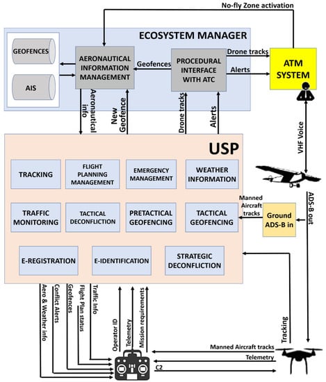
Figure 1.
Main actors involved in the demonstrations and high-level architecture of the U-space platform that provided proof-of-concept implementation of most of the initial U-space services within the USP (U-space Service Provider system).
In Figure 1, the following major components and actors were considered:
- U-space Ecosystem Manager: The U-space ecosystem manager interconnects all the U-space services providers to enable the interaction between them and acts as a governing body. It ensures equitable access to the airspace of all users and manages the interaction between U-space and conventional aviation, imposing a solution in those cases in which safety is compromised. The crucial principle is that this entity has the single source of truth for all information related to the operation of U-space within a defined area (such as a country or province) to which all U-space service providers connect to. To this end, the ecosystem manager provides several centralized services, such as the provision of reliable aeronautical and airspace data (restricted areas, temporarily restricted zones, etc.) and coordination with ATC, assuring levels of integrity, completeness and reliability of the information needed to the provision of U-space services. It is envisioned that in a future, the ecosystem manager will be run by the Member State, or a deputy thereof, and based on a highly redundant system to avoid the risk of failure.
- U-space Service Provider (USP) system: This system provides services essential for the drone traffic management. In this case, a modified version of the Unifly company (https://www.unifly.aero/) system was used, which supports the following U-space levels as defined by the blueprint: U1—foundation services and U2—initial services. In addition, Unifly’s U-space system also supports some basic U3 advanced services. It is expected that in the real implementation of the U-space architecture, multiple USP will provide the different services. In this case, the architecture was simplified to facilitate the demonstration activities. Then, in the rest of the paper all the references to the U-space Service Provider or USP correspond to the Unifly company implementation used in the tests.
- Air Traffic Controller (ATCO): ATM is a crucial actor in the U-space architecture to facilitate manned and unmanned operations and interactions in non-segregated airspace. Air traffic management will provide a direct line of communication between the ecosystem manager and air traffic control stations so that U-space/ATM communications can be established. The air traffic control working stations, as part of ATM, will utilize direct lines of communication to the Ecosystem Manager as the single source of information about drone traffic within their area of operation, in order to assure safe separation to manned traffic and for traffic alerting purposes.
- Drone pilot: Drone pilots are in charge of remotely piloting, supervising and monitoring drone flights (depending on the level of autonomy). Pilots carry out drone operations for both leisure and commercial purposes, so they can be categorized by the type of operation, as well as by the license they require to operate a specific drone, depending on the regulations for licensing, authorizations and identification.
- Drone operator: Drone operators are entities accountable for commercial operations of drones, which are authorized by the national competent authority. Operators manage a fleet of one or several drones and employ drone pilots as well as other personnel to execute the authorized operations. They are users of the services provided by the system.
On the one hand, one of the objectives pursued in this work was to test the procedures and advances in new services by using the most common drones’ configurations (multicopter and fixed-wing). In addition, to accomplish this objective and for increasing the casuistic of the results obtained, several commercial, off-the-shelf (COTS) autopilots and up to four different ground control stations (GCS) have been used to verify that it is possible to perform the expected actions with the most common UAS configurations. This approach allows the comparison of the flight behavior and procedure execution times needed by these different configurations for performing the commanded maneuvers. Table 1 shows the different drones used and their corresponding autopilots and GCSs.

Table 1.
Drones, autopilots and GCS software used during the flights.
On the other hand, for the scenario focused on the testing of new procedures for the safe integration of manned and unmanned platforms in the same airspace using the U-space services, the MRI TARGUS from INDRA was the manned-aircraft chosen for the demonstrations. This aircraft has a maximum take-off weight of 1230 kg, with an operational height of 14,000 feet and a cruise speed of 230 km/h.
All the demonstrations were executed in the ATLAS Test Centre allocated within a segregated airspace of 30 × 35 km up to 5000 ft altitude. Thanks to this segregated airspace, BVLOS flights of drones are allowed and coherent with the current Spanish RPAS regulation. Figure 2 shows the ATLAS facilities and the segregated airspace area.

Figure 2.
ATLAS test facilities located in Villacarrillo (Spain).
3. Design of Procedures Related to No-Fly Zones (NFZ)
One of the fundamental building blocks for structuring airspace within the U-space environment is the use of geofences. Geofences are airspace boundaries over geographical areas with the aim of prohibiting, restricting or containing drone operations within them, depending on the type of geofence used. These types of areas can be activated, changed or deactivated in real-time, and the updates transmitted to all drones and operators connected to the U-space ecosystem through the Geofence provision service. It is expected that autonomous operations will require drones to be constantly connected to U-space in order to maintain internal databases of geofencing locations consistently up-to-date. For drone operations supervised or directly controlled by a human pilot, geofence locations must be visualized on their primary display. However, the actual flight procedures with regard to geofences have not yet been established. Therefore, we developed recommended flight procedures around geofences based on quantitative evidence obtained through flight tests in three different kinds of scenarios, as it is shown in Figure 3.
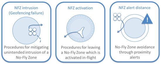
Figure 3.
Graphical summary of the scenarios tested related to no-fly zones.
The aim of these trials was to identify the fastest means of recovering from inadvertent infringements of geofence boundaries and to find the most effective way to alert the operator of an impending conflict with a geofenced area. The procedures were centered around the most stringent form of geofence, the so-called no-fly zone (NFZ). The scenarios were set up so that the drone would inadvertently breach a NFZ at some point during the flight, which would then trigger a response maneuver by the drone system or pilot. Several maneuvers were tested, including autopilot-guided and human-piloted flight, as well as pre-programmed drone functions such as “Return to Launch”. Each maneuver was timed from the moment that the drone entered the NFZ until the moment that it left it again. The most effective procedure was that which required the overall least amount of time and traversed the least distance within the NFZ.
To keep the scenarios realistic, two different types of commercial, off-the-shelf drones with autonomous flight capabilities were utilized for this analysis—a medium-sized fixed-wing and a large multicopter drone. These drones followed pre-programmed flight paths and were supervised by human pilots, who had the possibility of taking over manual control if necessary. No maneuvers were performed that were outside of the drones’ flight envelopes or the pilots’ personal safety margins.
3.1. No-Fly Zone Activation
This scenario was focused on testing of procedures to leave no-fly zones which were activated in flight due to the landing of a helicopter in that area. The aim was to gather first hand data on the performance of maneuvers to leave the NFZ utilizing different types of drones and different strategies. The NFZ dimensions were based on definitions provided in [6] concerning the size and shape of a zone which should be automatically generated when a helicopter enters VLL airspace. This area is a circular shape with its center on the position of the helicopter and a radius of 150 m. The vertical extension of the NFZ was set to the VLL ceiling (120 m above ground level).
The scenario is depicted on Figure 4 and the steps involved were the following:
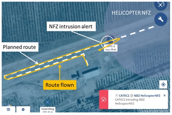
Figure 4.
NFZ activation scenario with the key elements highlighted.
- The drone took off from its departure point and embarked on a pre-programmed runway inspection mission;
- During the execution of the mission, a temporary NFZ was created at one of the thresholds of the runway, to simulate a helicopter approaching for landing; and
- The drone entered the temporary NFZ following its flight plan. Upon receiving a visual and auditory warning, the drone operator took corrective action to leave the NFZ as quickly as possible.
Three different types of corrective actions were tested to leave the NFZ: Closest Point (CP) (leave NFZ via the closest lateral point); Safe Altitude (SA) (leave NFZ via the closest lateral point whilst descending to a safe altitude of 30 m), and Return to Launch (RTL) (the drone leaves the NFZ via its “Return To Launch” (RTL) function).
Figure 5 shows the drone type, the type of procedure applied with each flight execution mode and the average of the results for four flights. The determining factor for these exercises was the time that the drone remained within the NFZ.
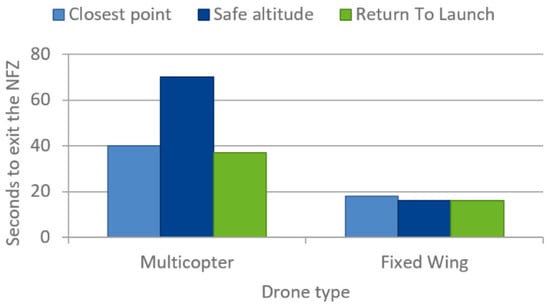
Figure 5.
NFZ activation results. The results shown are the average of four flights each rounded up.
Looking this figure, it becomes apparent that the fixed-wing drone was able to perform the procedures more quickly than the multicopter drone. This is logical due to the higher velocity of the fixed-wing drone. In general, there was no significant operational difference in the three maneuvers tested for each type of drone. However, a posterior briefing with the pilots highlighted that their preferred method of executing the escape maneuver was the “closest point” option, due to its simplicity and applicability in most situations. For instance, the “RTL” function only makes sense if the direction of the launch point coincides with the closest point to exit the NFZ, as it was the case in these trials.
An interesting observation is the obvious “spike” in-flight time of the multicopter drone performing the “safe altitude maneuver”. Instead of performing both maneuvers at the same time (as expected), the drone first came to a full stop, descended and then performed the change of direction. This sequential execution of events added additional time to the execution of the maneuver while it was in the NFZ.
3.2. No-Fly Zone Intrusion
This scenario was focused on testing the procedures to leave no-fly zones which were inadvertently flown into. The aim was to gather first-hand data on the performance of maneuvers utilizing an experimental large multicopter drone and different strategies.
The scenario is represented in Figure 6 and involved the following steps:
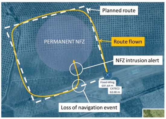
Figure 6.
NFZ intrusion scenario with the key elements highlighted.
- A hypothetical surveying mission of the fixed wing drone was launched which took it around a NFZ. After the first round, a “loss of navigation” event was simulated and the drone deviated from its flight plan directly into the NFZ; and
- An NFZ intrusion alert was received from the UTM platform, and the drone pilot performed the appropriate procedure to leave the NFZ as soon as possible.
Three different types of avoidance procedures were tested at two different velocities (5 m/s and 8 m/s):
- Return To Launch: The “Return To Launch” button was pressed as soon as the alert chimed. The drone would then engage the RTL mode and fly back to its origin;
- Manual flight: The procedure was to manually stop the drone and head back out the same way that it entered; and
- Autopilot-guided avoidance (waypoint): Once the alert was received, the pilot attempted to exit the NFZ by adding a new waypoint outside of the NFZ-area and letting the drone’s autopilot take it there. The drone executed this maneuver without any pilot control intervention.
The execution of each procedure was timed from the moment that the drone entered the NFZ to the moment it vacated it again. Figure 7 shows the type of procedure applied and the results of the procedure. In this case, each of the procedures was flown three times. It can be seen that the most consistently swift procedure for performing the maneuver was to take manual control of the drone and leave via the closest point of the NFZ boundary.
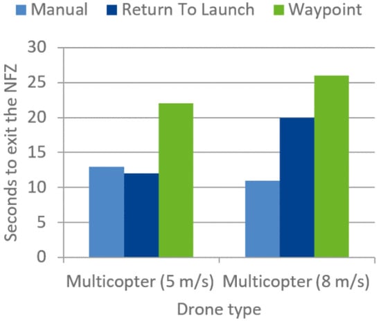
Figure 7.
NFZ intrusion results. The results shown are the average of three flights each rounded up.
3.3. No-Fly Zone Alert Distance
This scenario was focused on testing of procedures to avoid entering circular no-fly zones with additional “alert buffer zones”. The aim was gathering first-hand data on the performance of NFZ evasion maneuvers with common types of drones and different strategies. The vertical extension of the NFZ was set to 50 m above ground level, in order to test vertical NFZ evasion maneuvers as well.
This scenario is depicted in Figure 8 and the following steps were done:
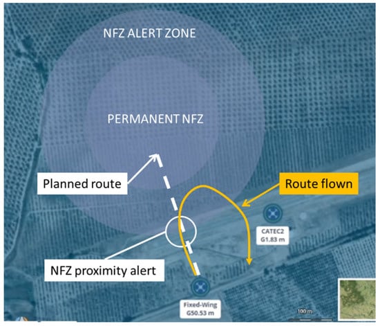
Figure 8.
NFZ alert distance scenario showing the key elements.
- An alert zone was generated which provided an additional safety buffer around the permanent NFZ;
- The fixed-wing drone embarked on a trajectory which would have taken it directly through the NFZ; and
- Once the proximity alert was activated, the drone pilot took corrective action to avoid the NFZ.
A total of 15 individual runs were performed to incrementally test all the buffer zone sizes from small radius to large radius. As soon as a drone was able to perform the avoidance procedure without infringing the NFZ, the test was considered successful. Different procedures were tested per type of drone.
The fixed-wing drone was flown under manual control for the entire duration of the flight. Two avoidance procedures were tested:
- Horizontal avoidance (HA): Once the alert was received, the pilot attempted to avoid the NFZ via a horizontal turn to leave the alert buffer zone via the nearest point whilst maintaining altitude.
- Vertical avoidance (VA): Once the alert was received, the pilot attempted to avoid the NFZ via a vertical climb to leave the alert buffer zone via the nearest point.
The large multirotor drone was tested for horizontal avoidance procedures flown under a combination of manual and autopilot guided modes. The following avoidance procedures were tested:
- Autopilot-guided avoidance (GA): The avoidance procedure was to place another waypoint outside of the alert buffer zone as soon as the alert chimed. The drone would navigate to this new waypoint automatically.
- Return To Launch (RTL): The avoidance procedure was to press “Return to Launch” (RTL) as soon as the alert chimed. The drone would then automatically engage the RTL mode and fly back to its origin.
- Manual to guided avoidance (MGA): The drone headed towards the No-Fly Zone under manual control. The avoidance procedure was to place another waypoint outside of the alert buffer zone as soon as the alert chimed. The drone would navigate to this new waypoint automatically.
Table 2 shows the drone type, type of procedure applied and the results of the procedure. In this exercise, the altitude of the fixed-wing was 30 m AGL and the speed 12 m/s, and the multicopter performed the operations at 60 m AGL and 8 m/s. The determining factor for these exercises was the horizontal distance traversed from the beginning of the NFZ alert buffer zone (last column of the table). The same flight profiles were repeated for each of the individual avoidance procedures and various buffer-zone dimensions, starting from the smallest one. The results presented were obtained from each of the executions. The procedures which did not cause an infringement of the permanent NFZ are marked in green and the corresponding buffer zone sizes which were used to define the minimum buffer zone dimensions. Essentially, the buffer zone dimensions were determined by the minimum values applicable to all avoidance procedures.
Table 2.
NFZ alert distance procedure results for two types of drones: Fixed wing and multicopter.
Looking at these results, we found that the minimum dimensions for NFZ alert distances for drones flying at the speeds that were tested are:
- 100 m horizontal from the beginning of the geofence; and
- 20 m vertical from the top of the geofence upwards (see Figure 9)
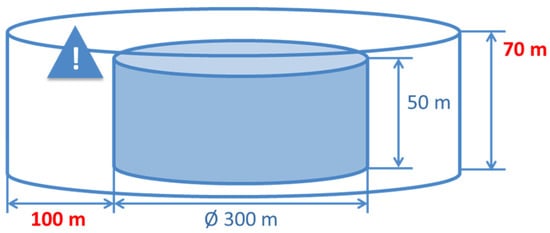 Figure 9. Minimum dimensions for NFZ alert distances found in our tests.
4. Ensure Separation with Manned Aircraft
Manned operations may enter VLL airspace for several reasons, both intentionally and unintentionally, which increases the risk of colliding with drones. On the one hand, the risk of planned operations within VLL airspace by manned aircraft can be mitigated if the manned-aircraft pilot makes use of the U-space services. For instance, during the planning of the operation, the Strategic Deconfliction service validates and checks for overlaps against all existing missions in the same time window, so the manned pilot could avoid conflicts with other VLL users prior to flight. On the other hand, an unplanned, conscious entry in VLL is considered risky (this could happen due for example to an emergency landing), and it is an important topic to address in order to assure a safe integration of manned and drone air traffic.
Therefore, we analyzed the unplanned, conscious entry into VLL scenario on the premise that the general aviation aircraft always have priority over drones. Here it is important to bear in mind that it is not yet clear whether the crew of manned aircraft will be connected to U-space services in the future. Especially because of workload and training concerns of the general aviation to understand and act according to the information presented in real-time by these services. Hence, we have considered that drones should be the actors that perform the contingency actions, and we have focused on those situations in which a manned aircraft needs to enter VLL airspace without prior notification or reservation. The approach to protect general aviation was to create short-time emergency geofences in order to restrict the drones’ flights until the general aviation aircraft abandon the VLL area. This approach is aligned with the CORUS project CONOPS (https://www.eurocontrol.int/project/concept-operations-european-utm-systems) where it is stated that: “Priority operations such as HEMS or police flights or military training shall be systematically protected by short term restrictions, and hence geo-awareness”. This approach was studied and tested in real flight demonstrations departing from a situation in which a general aviation aircraft flew at VLL altitudes in a zone where there were several drones performing flight operations. These demonstrations considered two main scenarios, one where neither U-space nor ATM knew the position of the general aviation aircraft, and the second where the general aviation aircraft incorporated a surveillance system (ADS-B in our tests).
In our implementation of the U-space services, communication between ATM and U-space were composed of three main components (see Section 2):
- Drone telemetry from U-space to ATM: JSON-type data with telemetry message was sent over the MQTT transport protocol.
- Drone alerts: If any of the drones break any of the flight restrictions, ATM receives an alert message from U-space (special field on the drone track itself).
- Dynamic geofence updates from ATM to U-space: ATM can update the geofence service data at any time, creating or deleting geofences and send a “new data available” message to alert U-space, allowing a real-time update.
As commented before, the first scenario studied considered the situation in which a manned aircraft did not have any way to report its position. Hence, neither ATM nor U-space were able to track it and required the participation of an ATCo for solving any possible conflicts. The flight tests were performed in an area where several drones were flying at the same time. These drones are tracked by U-space, so their position is available also in ATM. Figure 10 shows the HMI for the visualization of drones for both U-space and ATM.
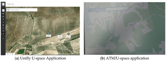
Figure 10.
Monitoring of drones in different platforms. (a) U-space application implemented by the Unifly company, and (b) Screenshot of the ATM HMI that monitors the information sent by U-space.
While drones were performing their operations, a manned aircraft without any tracking device needed to enter VLL airspace. In this case, the proposed procedure was that the crew informed ATM about the intent to operate in VLL airspace and the expected area of operation or, at least, its approximated position. In this case, the ATCos’ predefined action consists of creating a temporary geofence that covers the entire zone where the manned aircraft is operating. This geofence was then received by U-space and displayed to their users. In this situation, operators whose drones were inside the new temporary no-fly zone were alerted, so they were obliged to start the defined contingency procedure in order to avoid the manned aircraft. Once the manned aircraft left VLL airspace, the ATCo removed the geofence, and the drones’ missions were resumed. Figure 11 show these steps in the different applications in a graphical manner.
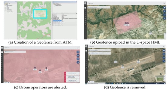
Figure 11.
Illustration of the steps followed in the first scenario where the proposed procedure was that the crew informed ATM about the intent to operate in VLL airspace and the expected area of operation. In this case, the ATCos’ predefined action consists of creating a temporary geofence that covers the entire zone where the manned aircraft is operating.
The second scenario tested a situation in which the manned aircraft was equipped with an on-board surveillance system (an ADS-B out device in our flight tests), so its position could be tracked by U-space through the traffic information service. This service allows the users to be aware of manned aircraft positions and provides part of the data that is used for the calculation of the conformance and anti-collision alerts. In fact, this real-time information of the general aviation aircraft position allows optimising the use of the airspace since it alleviates the need for establishing large geofence areas.
In our tests, the information regarding the manned aircraft position was obtained from a professional ADS-B in receiver integrated into the ATLAS facilities. Once received, these data were sent to the traffic information service of our U-space system, which in turn shared this information with the conflict resolution service and with the monitoring service, allowing the operators to have a view of the current situation in their HMIs. Figure 12 shows an example of the manned traffic information that the U-space users receive in their HMIs.
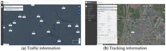
Figure 12.
Traffic information received by U-space users.
In this situation, U-space created a dynamic geofence around the manned-aircraft that was flying in VLL. As previously commented, this allows for a more efficient use of the airspace than in the first scenario, since the position of the general aviation aircraft is known in real-time. Moreover, this information was complemented with the conflict resolution services that provide warnings and collision alerts to the operators depending on the distance of their air vehicles to the manned aircraft. This service complemented the dynamic geofence, minimizing its application area since warning and alerts were also transmitted to the drones in order to make them aware of the presence of the GA aircraft with enough time to react. Figure 13 presents a screenshot of the operator’s interface during one of the flight tests performed. In this test, seven drones were flying simultaneously with a general aviation aircraft. Once the system detected that the aircraft was closer to the drones than the required safety distances, it alerted the affected operators about the collision risk. Once the operators received the warning, they started the associated contingency procedure.
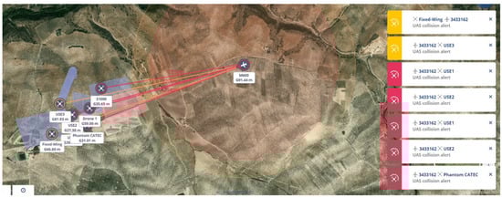
Figure 13.
Seven drones flying simultaneously with a general aircraft in VLL in an emergency situation.
Regarding the dynamic geofence created around the manned aircraft, the dimension was calculated taking into account the velocity of the aircraft and giving at least 120 s to the drone operator to perform the contingency action (reaction time of 60 s and descent from 120 m at least at 2 m/s). If the velocity of the manned aircraft is not known, a default distance of 6 km was used (using 180 km/h as a mean for the aircraft velocity in VLL). The shape of the proposed geofence is presented in Figure 14. In those cases where neither the track direction nor the velocity is known, the geofence consisted of a cylinder centered in the aircraft with a radius of 6 km and covering the entire altitude range from 0 to 120 m.
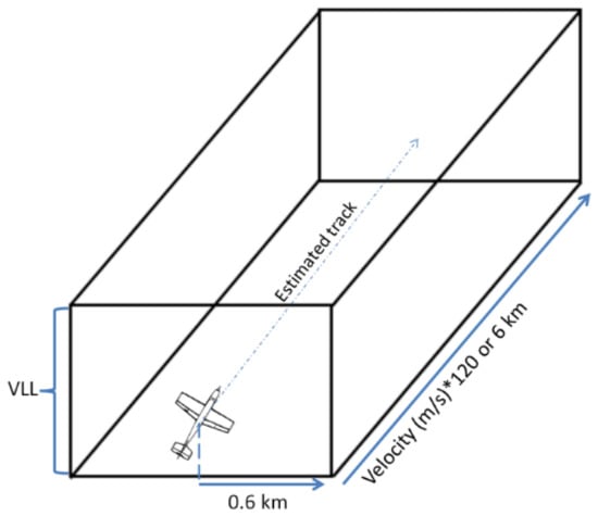
Figure 14.
Dynamic geofence considered around the manned aircraft in VLL.
In addition to the procedures followed for maintaining a safe distance with manned aviation using U-space services, we studied the possibility of using cooperative detect and avoid techniques. This extra functionality could be very interesting as an extra safety layer in case drones loses connectivity with U-space, and neither of the previously described procedures works as expected. The pingRX ADS-B dual receiver from uAvionix was directly connected to the drone’s autopilot. The connection of this sensor is shown in Figure 15a. In that way, ADS-B compliant aircraft within an estimated 50 km range was detected directly by the drone’s autopilot and the received data sent to the GCS through the telemetry channel. This information, as it is shown in Figure 15b, was displayed on the ground control station, providing the operator a complementary situational awareness that could be used in case U-space services are not working correctly.
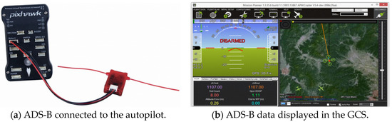
Figure 15.
The pingRX ADS-B dual receiver from uAvionix was directly connected to the drone’s autopilot.
Since the ADS-B receiver is directly connected to the drone’s autopilot, it allows activating an autonomous functionality called “AVOID_ADSB” that attempts to avoid manned vehicles based on the ADS-B sensor’s output. Entry into this mode is automatic when avoidance is necessary based on the parameters below:
- The horizontal distance in meters that should be considered a near-miss;
- The vertical distance in meters above or below the vehicle that should be considered a near-miss;
- How many seconds in advance of a projected near-miss (based on the vehicle’s current position and velocity) the vehicle should begin the avoidance action; and
- How the vehicle should respond to a projected near-miss (i.e., climb or descend, move horizontally, move perpendicularly in 3D, RTL or hover)
This functionality (automatic avoidance) was evaluated very positively by the drone pilots because it helps to increase the safety in the operations, especially in those cases in which the communication link with the drone was lost, and the operator cannot command any action to the drone.
In conclusion, we consider that the use of surveillance information will allow making better use of the airspace, and its use should be promoted along general aviation aircrafts. Moreover, the use of ATCo communications could be an interesting backup option for non-equipped aircraft, and the use of ADS-B in systems (or any equipment that allows to directly receive the positioning information from the aircraft surveillance on-board systems) on drones is very interesting in order to add an extra safety layer to the operation, both in case of U-space failures and also in case of loss of communication with the GCS.
5. Autonomous Non-Cooperative Detect and Avoid Technologies and Its Integration in U-Space
We considered the integration of advanced functionalities in U-space, based on the concept of future intelligent drones equipped with on-board sensors with high computational capabilities. We tested the integration of on-board detect and avoid (DAA) capabilities and the implications thereof related to the U-space services. Particularly, this scenario addressed a situation where a drone equipped with the proper sensors executed a previously accepted flight plan at very low altitude and detected an unexpected static ground obstacle. Then, the drone had to autonomously generate a new flight plan to avoid it and integrate it into the envisioned U-space services (specifically the Flight Plan Management service). Our goal was to identify which procedures should be followed and how they should evolve to facilitate DAA capabilities in the near future.
A multirotor type drone was used for this scenario due to its superior maneuverability compared to fixed-wing platforms and mainly due to its ability to hold its position while hovering during “flight plan negotiation” using the U-space services. The drone was equipped with an on-board computer (Intel NUC i7), running Ubuntu 16.10 as the operating system and ROS Kinetic as the framework to execute the autonomous behavior. The NUC was connected to the autopilot and could communicate with the ground segment through a radius-link based on Ubiquity Rocket M5. Therefore, it could be commanded and monitored from the ground control station (GCS). The drone used a Pixhawk type autopilot running the APM firmware, able to execute pre-charged flight plans but, also, to track online flight commands provided by an external computer, based on the MAVLINK protocol. A 3D- LIDAR sensor (Ouster OS1-16) was integrated in the drone to collect a point cloud of the environment around. A path planner based on the Lazy Theta * algorithm [12] was used to generate an avoidance path based on the octomap generated using the information provided by the 3D-LIDAR sensor.
On ground, two laptops were used as ground control stations (GCS). The first one, based on Ubuntu 16.10 and ROS Kinetic, was in charge of commanding specific orders to the drone (start mission, take off, land, etc.) and monitoring its autonomous behavior. The second one, based on Windows 10, was monitoring the telemetry data of the drone and forwarding it to the U-space service provider (USP) but also communicated the reserved plan to the drone and asked for new flight plans according to the drone requests using the Mission Planner commercial control station software.
The Unifly USP was accessible via the internet and connected to the drone telemetry through Mission Planner. The USP was used to manage the flight plans, reserving a 4D-tube with a radius of 50 m around the requested flight plan.
The tests were also held at ATLAS and the ground obstacle considered during the flight was a building with an altitude of around 10 m. The following procedure was tested:
- A flight was planned in the USP interface. No conflict was found, and the flight plan was accepted.
- The flight plan was selected through the GCS and uploaded to the drone.
- A start command was sent to the drone, which took-off and started tracking the plan while collecting data from the environment using its onboard sensor.
- The drone detected an obstacle (see Figure 16) within the plan.
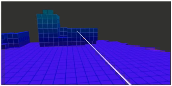 Figure 16. Image showing the environment representation based on the LIDAR measurements under the ROS environment.
 - The autonomous path planning (Lazy Theta *) generated a safe avoidance path as it is shown in Figure 17.
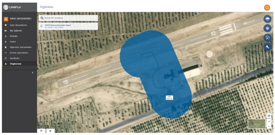 Figure 17. Image from Unifly USP showing the final trajectory performed by the drone and the whole area reserved in the U-space system.
 - As the path deviation was not large enough to exceed the boundaries of the 3D-tube reserved in the U-space system, it was not required to request a new flight plan to the system.
- The drone executed the new generated plan and avoided the unexpected obstacle.
It should be noticed that the flight plans were designed at very low altitude (8 m) during the tests in order to allow the potential collision with ground infrastructures. In addition, as the generated flight plans were within the “4D tube” initially accepted by the USP, it is not necessary to request a new flight plan reservation if the deviation due to the avoidance of the obstacle is within the limits of the “4D tube”. Figure 17 shows the drone trajectory performed during the demonstration flight, and it was always into the reserved area.
The new flight plan generated should be safe (related to the distance to the obstacle), and it should be accepted by the U-space system (related to the previously planned flight).
Up to now, there is no common minimum distance that a drone should keep with respect to static obstacles that is accepted by all standardization bodies. Based on different regulation/standardization resources (EASA, CORUS, DO-276C, EUROCAE WG-105), this value varies from few meters to hundreds of meters, taking into account different parameters, such as the weight and type of the drone. In any case, none of these values considers unexpected obstacles. During our flights, the minimum distance to the building was around 20 m. Taking into account that data collected outdoors by the 3D-LIDAR can be collected reliably at 30–40 m, keeping 20 m from an unexpected static obstacle seems to be adequate.
Finally, and after all the flight demonstrations, the possible need that regarding unexpected ground obstacles has been detected, and a new service may be defined to report the U-space about their detection, enabling the possibility that the U-space system would able to alert other drones’ operators about potential new obstacles, minimizing risks even if these drones are not equipped with onboard sensors able to detect the obstacles by themselves.
6. Conclusions and Future Work
This work has presented the main results obtained in SAFEDRONE U-space demonstration project. First, results from the tested geofence procedures showed that the most efficient means for avoiding and exiting no-fly zones vary significantly depending on the type of drone, the type of flight strategy, drone velocity, and the level of pilot interaction. It has been found that, for mass-market, small-size fixed-wing, and multicopter drones, the best procedure for avoiding and exiting no-fly zones is to:
- Take manual control of the drone, and
- Evade the NFZ or leave via the closest point
It was also found that no abrupt control inputs or maneuvers outside of the performance envelope of the drone were required to perform these procedures, therefore showcasing that they can be flown in a safe manner without endangering aircraft or people on the ground.
Moreover, it is recommended that drone operators familiarize themselves with the vehicles that they operate prior to operation. It is important to analyze the fastest way of initiating a reactionary maneuver to a contingency situation. In the drones that were used for the trials, taking manual control of the vehicle was always the most effective method of leaving a geofence that was unintentionally infringed. However, this may not apply to vehicles with higher levels of automation.
Secondly, and in order to ensure the separation with manned aircraft, we consider that the use of surveillance information will allow for making a better use of the airspace shared with general aviation aircrafts. Moreover, the use of communication with air traffic control could be an interesting backup solution for non-equipped aircraft, and the use of “ADS-B in” receivers (or any equipment that allows to directly receive the positioning information from the aircraft on-board surveillance systems) on drones is very interesting in order to add an extra safety layer to the operation, both in case of U-space failures and also in case of loss of communication with the GCS.
With respect to non-cooperative detect-and-avoid functionalities, the demonstration flights have shown the technical feasibility of integrating these advanced functionalities into drones to autonomously detect and avoid obstacles. Thus, the integration of U3 services such as “detect-and-avoid” is technically feasible. However, due to the current range limitation of lightweight 3D sensors, this functionality could limit the nominal speed of the drone. Moreover, U-space service providers are not currently considering the integration of this type of advanced capabilities in their architectures. It might be useful to generate specific alerts, notifications or commands in the U-space system related to this functionality.
Finally, with respect to future work, it is planned to extend our results on a larger scale. In our tests, a wide range of drone maneuvers related to geofences and associated flight profiles, maneuver execution times and pilot reaction times have been gathered. This data, along with the information from detect and avoid and use of dynamic geofences, will be modelled and used as input to a series of large-scale fast-time simulations of drone operations, with the aim of further determining adequate procedures and standards for U-space.
Author Contributions
Conceptualization: V.A., Á.M., I.M., and A.O.; methodology: V.A. and F.A.; software: V.A., I.M. and J.J.A.; formal analysis: V.A., M.G., and D.J.; investigation: V.A., M.G., A.M., J.J.A., and I.M.; resources: F.A., A.V., and A.O.; data curation: V.A., M.G., and D.J.; writing—original draft preparation: V.A., Á.M., J.J.A., and I.M.; writing—review and editing: F.A., A.V., D.J., I.M., and A.O.; visualization: V.A. and M.G.; supervision: F.A. and A.V.; project administration: A.V. and A.O.; funding acquisition: A.V., D.J., and A.O. All authors have read and agreed to the published version of the manuscript.
Funding
Authors have received funding from the SESAR Joint Undertaking under grant agreement no. 783211 under European Union’s Horizon 2020 Research and Innovation Programme.
Acknowledgments
Authors would like to thank rest of SAFEDRONE consortium: INDRA, ENAIRE, UNIFLY, and IAI for their collaboration in the project activities, and without their contribution, the results presented in this paper would not have been possible.
Conflicts of Interest
The authors declare no conflict of interest.
References
- MacIas, M.; Barrado, C.; Pastor, E.; Royo, P. The Future of Drones and their Public Acceptance. In Proceedings of the AIAA/IEEE Digital Avionics Systems Conference, San Diego, CA, USA, 8–12 September 2019; Institute of Electrical and Electronics Engineers Inc.: Piscataway, NJ, USA, 2019. [Google Scholar]
- SESAR Joint Undertaking. European Drones Outlook Study; SESAR Joint Undertaking: Brussels, Belgium, 2016. [Google Scholar]
- Mazur, M.; Wisniewski, A.; McMillan, J. PwC Global Report on the Commercial Applications of Drone Technology; PwC: London, UK, 2016. [Google Scholar]
- EUROCONTROL. RPAS ATM CONOPS Edition 4.0; EUROCONTROL: Brussels, Belgium, 2017. [Google Scholar]
- SESAR Joint Undertaking. U-Space Blueprint; SESAR Joint Undertaking: Brussels, Belgium, 2017. [Google Scholar]
- SESAR Joint Undertaking. U-Space Concept of Operations Edition 3.00.02; SESAR Joint Undertaking: Brussels, Belgium, 2019. [Google Scholar]
- Barrado, C.; Boyero, M.; Brucculeri, L.; Ferrara, G.; Hately, A.; Hullah, P.; Martin-Marrero, D.; Pastor, E.; Rushton, A.P.; Volkert, A. U-space concept of operations: A key enabler for opening airspace to emerging low-altitude operations. Aerospace 2020, 7, 24. [Google Scholar] [CrossRef]
- Pérez-Castán, J.A.; Gómez Comendador, F.; Cardenas-Soria, A.B.; Janisch, D.; Arnaldo Valdés, R.M. Identification, categorisation and gaps of safety indicators for U-space. Energies 2020, 13, 608. [Google Scholar] [CrossRef]
- Geister, R.; Peinecke, N.; Sundqvist, B.G.; Del Core, G.; Timmerman, B.; Boer, J.F.; Zimra, D.; Steinbuch, Y.; Batzdorfer, S.; Grevtsov, N.; et al. On-Board System Concept for Drones in the European U-space. In Proceedings of the AIAA/IEEE Digital Avionics Systems Conference, San Diego, CA, USA, 8–12 September 2019; Institute of Electrical and Electronics Engineers Inc.: Piscataway, NJ, USA, 2019. [Google Scholar]
- Doole, M.; Ellerbroek, J.; Hoekstra, J.; Mennella, A.; Onate, M. Drone information service requirements for U-space. In SESAR Innovation Days; SESAR Joint Undertaking: Brussels, Belgium, 2018. [Google Scholar]
- Peinecke, N.; Limmer, L.; Volkert, A. Application of “Well Clear” to small drones. In Proceedings of the AIAA/IEEE Digital Avionics Systems Conference, London, UK, 23–27 September 2018; Institute of Electrical and Electronics Engineers Inc.: Piscataway, NJ, USA, 2018. [Google Scholar]
- Faria, M.; Marín, R.; Popović, M.; Maza, I.; Viguria, A. Efficient Lazy Theta* Path Planning over a Sparse Grid to Explore Large 3D Volumes with a Multirotor UAV. Sensors 2019, 19, 174. [Google Scholar] [CrossRef] [PubMed]

© 2020 by the authors. Licensee MDPI, Basel, Switzerland. This article is an open access article distributed under the terms and conditions of the Creative Commons Attribution (CC BY) license (http://creativecommons.org/licenses/by/4.0/).