Abstract
Urban airspace environments present exciting new opportunities for delivering drone services to an increasingly large global market, including: information gathering; package delivery; air-taxi services. A key challenge is how to model airspace environments over densely populated urban spaces, coupled with the design and development of scalable traffic management systems that may need to handle potentially hundreds to thousands of drone movements per hour. This paper explores the background to Urban unmanned traffic management (UTM), examining high-level initiatives, such as the USA’s Unmanned Air Traffic (UTM) systems and Europe’s U-Space services, as well as a number of contemporary research activities in this area. The main body of the paper describes the initial research outputs of the U-Flyte R&D group, based at Maynooth University in Ireland, who have focused on developing an integrated approach to airspace modelling and traffic management platforms for operating large drone fleets over urban environments. This work proposes pragmatic and innovative approaches to expedite the roll-out of these much-needed urban UTM solutions. These approaches include the certification of drones for urban operation, the adoption of a collaborative and democratic approach to designing urban airspace, the development of a scalable traffic management and the replacement of direct human involvement in operating drones and coordinating drone traffic with machines. The key fundamental elements of airspace architecture and traffic management for busy drone operations in urban environments are described together with initial UTM performance results from simulation studies.
1. Introduction
The world has become increasingly familiar with drones and the very real benefits of commercial applications in various areas, including: rapid information gathering; logistical support; risk reduction; overall cost-savings. Examples of this include: precision agriculture and mapping [1,2]; critical infrastructure inspection [3,4]; ad-hoc wireless network provision [5]; search and rescue [6]; delivering critical medical supplies [7]; natural disaster and humanitarian relief aid [8]. More fantastic, futuristic scenarios of Drones and Urban Air Mobility (UAM) are also underway, including the potential for 5-min cross-city Air-Taxi hops and the on-demand delivery of your favourite fast-food dishes, right to your backdoor [9,10,11].
The continued growth of the global drone industry and its associated economic and societal benefits have been widely reported by various commentators [12,13,14,15,16,17], notwithstanding the need to address the ongoing inter-dependent challenges of reliable technologies and regulated flight-operation [18,19,20,21]. Reliable technologies include: drones suitably configured to carry out end-use applications in their operating environment; onboard situational awareness capability; very low level (VLL) airspace monitoring; robust and secure command and control (C2) and data-link communication. Other reliable technology areas include a highly automated drone airspace traffic management system to handle various VLL airspace operational environments, flight-planning, deconfliction, optimisation and emergency event handling. Regulated flight-operations include the legislative instruments that ensure that lawful drone application and services are conducted in a safe and secure manner whilst minimising privacy invasion and nuisance impacts.
It is predicted that drone air traffic will increase over the coming decades with SESAR’s Outlook study (2016) estimating 100,000 delivery drones in Europe by 2050 [22], whilst the FAA have predicted that the commercial, small non-model UAS fleet, in the USA, is forecast to nearly triple from 277,386 in 2018 to 835,211 in 2023 [23]. A substantial part of this commercial service activity is likely to be based around urban centres with urban air mobility (UAM), which has been defined as safe and efficient air traffic operations for drones, including package delivery and air-taxi services in a metropolitan area [9] and which is likely to play a central role in the global drone marketplace. Estimates of activity vary and include the potential to deliver over 1.4 billion packages in the USA by 2030 [10] or an estimated 87,000 drone flights per hour to satisfy delivery demand over Paris, France [24]. Meanwhile, densely populated urban areas and cities are increasing in terms of human activity. Since 2007, more than half the world’s population has been living in cities, and that percentage is projected to rise to 60% by 2030. Cities and metropolitan areas are the powerhouses of economic growth, contributing about 60% of global GDP [25].
U-Flyte was formed to tackle some of the key research challenges associated with the design and construction of Urban UTM systems with a focus on key aspects, including: urban environment; airspace architecture; flight planning; deconfliction and emergency event handling, especially as these relate to potentially high drone traffic loadings in busy VLL urban airspace environments. The paper is organised into an initial review of contemporary high level UTM and U-Space initiatives, as well as related UTM R&D topics, followed by a more detailed exploration of U-Flyte’s research activities in developing airspace architecture and traffic management systems. An urban UTM simulator was designed and constructed using the outputs from this research work and some of the initial UTM performance results are presented.
2. Contemporary Unmanned Traffic Management Research and Development
Contemporary Unmanned Traffic Management research can be categorised into high-level national/international initiatives as well as more focused R&D activities by smaller groups of researchers and industry organisations.
2.1. Overarching National and International Unmanned Traffic Management R&D Initiatives
A number of conceptual frameworks, platform architectures, methodologies and practical demonstrators have been developed across the globe over the last few years to attempt to tackle the complex challenge of how all of this civilian drone traffic management activity is actually going to work. These activities are in response to modern world expectations and commercial service demands and are counter-balanced by technology developments and regulated operation. These initiatives include the USA’s Unmanned Aircraft Systems Traffic Management (UTM) system, initially conceived by Dr. Parimal Kopardekar in 2014 and developed at NASA’s Ames Research Centre [26]. The latest Concept of Operations (ConOps) V2.0, [17] describes UTM as “a community-based, cooperative traffic management system, where the Operators and entities providing operation support services are responsible for the coordination, execution, and management of operations, with rules of the road established by FAA”. This system includes a set of federated services, including: to supporting the safe and secure conduct of UTM operations including areas such as; flight operations planning, communications, separation and weather. This is an all-encompassing framework for managing multiple UAS operations.
U-space, developed in 2017 by Single European Sky ATM Research Joint Undertaking (SJU), ref. [27] comprises a set of services and procedures relying on a high level of digitalisation and the automation of functions to support safe, efficient and secure access to airspace for large numbers of drones. U-Space is an enabling framework to support routine drone operations, addressing all types of missions, including flight-sorties in and around airports as well as enabling complex drone operations with a high degree of automation to take place in all types of operational environments [28]. Other similar drone traffic management frameworks to UTM/U-Space models include the Civil UAS Operation Management System (UOMS) in China and Japan’s UTM Consortium (JUTM), [29]. These overarching UTM/U-Space frameworks are supported by real-world demonstrations and testing through the National Aeronautics and Space Administration (NASA) Technology Capability Level (TCL), FAA UTM Pilot Program (UPP), and UAS Integration Pilot Program (IPP) demonstrations in the USA [17], and the European Network of U-Space Demonstrator in Europe, overseen by Eurocontrol [30] and SESAR [31]. The Joint Authorities for Rulemaking on Unmanned Systems (JARUS) is a group of experts gathering regulatory expertise from 61 countries, whose purpose is to recommend a single set of technical, safety and operational requirements for the certification and safe integration of UAS into airspace and at aerodromes. One example is the Specific Operational Risk Assessment (SORA) specification which sets out a risk assessment methodology which seeks to establish a sufficient level of confidence that a specific UAS operation can be conducted safely [32].
2.2. Contemporary Research in Unmanned Traffic Management Systems
A number of researchers have explored some key aspects of UTM, including one group [33] who report on the potential shortcomings of existing centralised UTM and U-Space service architectures in favour of a more distributed approach based on low-altitude airspace modelled as a weighted multilayer network of nodes and airways. Their research reported on various 3D path-finding algorithms for drones, including A*, Dijkstra, dynamic A* (AD*) and Lazy Theta*. They assessed optimum path-finding, examining three heuristics; static path planning, probabilistic dynamicand a local pheromone guided heuristic. They reported that the latter out-performed the former when handling higher levels of drone traffic. Researchers at Iowa State University, USA [34] developed a deep multi-agent reinforcement learning framework that was capable of identifying and resolving conflicts between aircrafts in a high-density, stochastic and dynamic en-route sector with multiple intersections and merging points. They highlighted that the key challenge with managing low altitude and urban air mobility traffic was to provide real-time advisories to aircrafts to ensure safe separation both along air routes and at the intersections of these air routes. Their results demonstrated that their framework was able to resolve 99.97% and 100% of all conflicts both at intersections and merging points, respectively, in extreme high-density air traffic scenarios. A SESAR Horizon 2020 funded project (DREAMS) [35] examined drone information service demands for enabling safe drone operation in VLL airspace with an emphasis on the urban environment, and carried out a gap analysis on existing information services from manned aviation and current U-Space service providers in line with drone operator and user requirements. Their research highlighted some critical present-day shortcoming’s relevant to implementing urban UTMs, including drone traffic activity and flow management. Additional research in related areas of 4D airway modelling and conflict detection [36], as well as genetic simulation framework using a dynamic hexadecimal tree for conflict detection over Braunschweig city [37], produced promising results. Researchers at Linköping University (Sweden) [38] reported that second-order issues or side-effects occur when using basic UTM tools (e.g., geo-fencing, detect-and-avoid, layering), on intense simulated random point-to-point city traffic. They concluded that more advanced UTM tools are required that support the optimization and automatic computation of airspace solutions. Limited research has been conducted in examining and modelling risk in urban environments where interesting approaches, incorporating population density, obstacles, sheltering and no-fly zone layers, have been explored [39,40]. Other researchers have investigated and developed conceptual risk-based assessment frameworks incorporating contingency and failure analysis over urban environments [41].
More industry focused research includes Uber’s review of electric Vertical Take-off and Landing (eVTOL) air-taxis over urban environments with an emphasis on eVTOL platform performance, certification and traffic management for, largely, point-to-point fixed-base Vertiports [42]. The DLR research team examined the use of aircraft safety bounds or safety ellipsoids surrounding drones, geofencing and the use of strategic and tactical deconfliction in airspace, which is cell based with overall traffic management governed by cell capacity limits [43]. Airbus’ “Blueprint for the Sky” takes a broader view on drone operations, covering safety, self-piloting, self-management and airspace that is shared, harmonized, fully accessible and future proofed. In this blueprint, airspace is structured based on environment and traffic activity type including; basic flight, free route, corridors and fixed route structures [44].
2.3. Research Gaps in Development and Implementation of Urban UTM
Cities and urban spaces are characterised as centres with significant human population densities, high-value infrastructure and with a wide variety of associated socio-economic activities. It is more probable than not that urban drone flights will be in relatively close proximity to human activity on the ground below in one form or another over the course of their journey. The current architectures for USA’s UTM and Europe’s U-Space do not address key operational aspects unique to urban environments and, even where some relevant topics are mentioned, these lack the necessary level of detail. At first glance, both architectures appear comprehensive, sharing common features for handling drone traffic, since both are modular in structure, promote the concept of federated data and information services and support the use of industry standards. Both USA’s UTM and Europe’s U-Space detail various data and information services that can be provided to UAS operators by UTM service suppliers/providers (USS in USA, USSP in Europe), as shown in Figure 1.
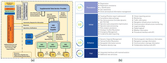
Figure 1.
(a) Schematic of USA’s UTM architecture [17]; (b) Europe’s U-Space Services [30].
However, little guidance or direction is provided as to how urban ground and air risk should be addressed or airspace constructed over these densely populated environments. It is unclear how these proposed data and information services, managed by USS and USSPs, can be integrated and implemented in busy urban UTMs in order to: (1) address risk; (2) model airspace; (3) manage high volumes of drone movements. Relevant data and information inputs for these three activities are cited, but how these inputs are integrated and structured into practical urban air traffic systems to manage potentially hundreds, if not thousands, of drone movements per hour over cities is less clear. Are there multiple USS/USSP covering various sections of a city? Will current disparate data inputs and information services (e.g., weather, terrain, communication coverage) be interpreted differently by different USS/USSPs, as well as drone operators themselves? Who has responsibility for overseeing and coordinating drone traffic? How are strategic (pre-flight) and tactical (in-flight) deconfliction scenarios for trans-urban flight services handled, potentially involving multiple USS/USSPs, drone operators, air traffic coordinators and managers? Does traffic management involve a human air-traffic controller and individual drone operators? How are traffic data and instructions relayed back and forth? If a collision occurs, how are responsibilities and costs apportioned where there could be multiple actors and factors involved?
The primary safety hazards posed by drones operating in an urban environment are collisions between a drone and another airspace users, as well as the impact on infrastructure, objects and people [45] on the ground, giving rise to damage, injury or possibly fatalities. The risks associated with these safety hazards must be addressed through the appropriate certification of drones for operation over an urban environment, coupled with comprehensive airspace architecture and dependable traffic management. Conventional drone risk analysis modelling methodologies, such as SORA, are useful for assessing risk for a single or low number of drones operating in relatively un-complicated real-world environments (e.g., sparsely populated, rural areas). However, this methodology may not be best suited in scenarios where high volumes of drone traffic are projected to operate in the near future over densely populated environments [44]. A typical metropolitan area of 25 km × 25 km could be classed as largely homogenous in terms of risk, since this space will have some level of human activity present, whether this is related to residential, industrial, retail-based, educational, transportation or recreational activities. Some of this activity may be indoors and some of this activity may occur un-protected out in the open. Urban ground risk can, therefore, be classed as omnipresent, where populated areas, buildings, infrastructure, transportation networks and associated human activity can be found throughout the environment to one degree or another. More vulnerable dynamic human activity (outdoor gatherings and sporting activities) can be even more challenging to locate and predict.
Key gaps in developing urban UTM systems are:
- Identifying and categorising unique characteristics of busy VLL urban environments;
- Drafting pragmatic approaches to addressing risk;
- Lack of guidance regarding the design and development of urban airspace architecture;
- Poorly laid-out framework as to how urban traffic management systems should be operated.
This lack of an overarching framework in terms of how risk is modelled, airspace structured, and traffic management implemented over urban environments has impacted how the wider research community is attempting to deal with architecture and traffic management aspects for developing urban UTM. This has resulted in a disconnect between airspace modelling and traffic management, giving rise to the development of a wide variety of proposed architectures and methodologies without any real agreement as to how these could be pragmatically implemented. A secondary impact has been the on-going stalemate situation over the past five years in how commercial fleets of BVLOS drones are operated over urban environments. A third impact has been the inefficient development activities undertaken by countless research groups, start-up enterprises and technology companies, all attempting to solve this same, single problem (e.g., DLR [43], Uber [42] and Airbus [44]).
The main focus of this paper is addressing these current shortcomings through an examination of the core characteristics of drone operation in urban environments, how risk can be addressed and through proposing a novel approach to airspace design as well as associated traffic management systems. The research work in urban UTM, carried out by the U-Flyte R&D team, based at Maynooth University, Ireland, is described and discussed. The initial performance results from U-Flyte’s urban UTM prototype simulation platform are also presented.
3. Urban Airspace Architecture and Traffic Management Systems
3.1. Urban UTM: Problem Definition and Research Questions
Current regulations for operating unmanned aircraft systems (UAS) in a low-level flight environment are quite restrictive. In Ireland, similar to other countries, these include restrictions on drone flight operations in controlled airspace surrounding airports, as well as restrictions to remain below 400 ft and not fly further than 300 m outside of one’s direct line of sight with the aircraft [46]. It makes perfect sense for a human operator to have control over the drone when the drone is operated in the visual line of sight, since the operator can see the drone as well as other objects, such as buildings, a nearby powerline or a group of people on the ground or, indeed, any other drone operating in the vicinity. However, there is an increasing demand for additional services and benefits by enabling drones to operate beyond the visual line of sight (BVLOS) and carry out a range of data gathering, logistical and specialist commercial services. However, as soon as the physical visual connection between operator and drone is broken, there needs to be a way of assessing and controlling where the drone is, where it can go and what it can do and to do this in a safe, responsible and regulated manner. These systems also need to be able to handle not just single BVLOS drone flights but potentially multiple drones in relatively close proximity. There is a pressing requirement for a comprehensive system to handle the overall management of BVLOS drone traffic in environments, including over cities and towns. The U-Flyte high-level conceptual overview of an Urban UTM, as shown in Figure 2, includes foundational, operational as well as regulatory and governance layers. The main focus of this paper will revolve around the operational layer shown in Figure 2.
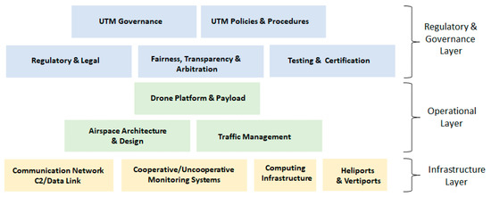
Figure 2.
Conceptual overview of an Urban UTM comprising three layers: foundational; operational; regulatory and governance.
The required operational capabilities and functions of a modern day urban UTM platform are manifold. One key requirement is a knowledge of the very low level (VLL) urban airspace with a clear indication of where drones can or cannot fly at any particular time. The UTM needs to know the location of all current airspace users at any one time, as well as examining planned and real-time journeys in order to be able to organise traffic and manage any potential conflicts. The UTM needs to be able to monitor the progression of traffic and communicate with the airspace users all of the time. The UTM needs be able to intervene in an emergency event and to handle such a situation in real-time whilst minimising the impact on the rest of the un-affected airspace. In short, the UTM needs to understand all relevant environmental information and dynamic inputs in order to be able to manage traffic and enable the safe and responsible operation of drones over cities and towns.
Key challenges associated with developing an urban UTM platform:
- Understanding the key risk characteristics associated with an urban UTM;
- Ground and air risk;
- Designing an airspace model that will support urban UTM operations;
- Architecture and structure;
- Developing urban drone traffic management;
- Ability to carry out deconfliction, optimisation and emergency event handling in real-time 4D;
- Development of a configurable, computationally scalable, highly automated UTM system that can be adapted for any city or urban environment.
Other key aspects underpinning urban UTM include; training and qualifications, drone registration, weather information, micro-climate models, as well as a dependable onboard detect and avoid (DAA) system, ground-based VLL airspace monitoring, auto-landing/take-off systems, ATM integration, communication network and navigation services, which are also required but will not be explored in this paper. These challenges provide the rationale underpinning the research described in this paper, which can be grouped under three headings:
- Environment and Operational Data: Identifying, collating and analysing relevant data inputs that can be used to design airspace architecture.
- Airspace Architecture: This is the multi-dimensional map or graph indicating where drones can or cannot fly, how airspace is structured and how drones can navigate through this space.
- Drone Traffic Management: Drone traffic management comprises three core dynamic traffic features: safety tube for drone trips, optimised pathfinding incorporating strategic/tactical deconfliction and emergency event handling. All of these activities need to be capable of operating in 3D airspace in real-time (i.e., 4D environments).
These challenges are formulated into three broad research areas: urban VLL environment characteristics; airspace architecture; traffic management systems. Each of these three areas comprises a number of topics, as shown in Figure 3, each of which is explored and presented in more detail in the following sections. The initial results of U-Flyte’s urban prototype UTM platform simulator, which was constructed and tested using the concepts developed from this research work, are also presented.
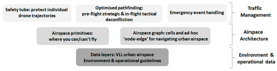
Figure 3.
Schematic of three overarching urban UTM-related research challenges and associated topics addressed in this paper.
3.2. Pragmatic Approaches to Addressing Risk Aspects Associated with Urban UTM Operations
The fundamental characteristics underpinning any UTM airspace architecture are the digital geospatial representations of the VLL real-world environment and the set of rules and protocols that govern all dynamic operations and activities in order to maintain the integrity and safety of the airspace. Secondary concerns include the privacy, nuisance and environmental issues associated with drone activity, but these aspects will not be addressed in this paper. The main source of risk revolves around flying several unmanned aircrafts simultaneously over a busy, populated and built-up environment. This overall risk can, in turn, be classified into two main risk sources, namely:
- Ground risk: hazards posed by drone operations to ground objects and human related activities;
- Air risk: hazards posed by a drone in flight to other drones and other airspace users.
Risk modelling for drone operations over urban environments has not been adequately investigated nor have any suitable protocols, standards or methodologies, that address the highly complex environment of dense drone traffic operations over cities, been developed. Computing ground risk for urban drone operations can be challenging, since many variables, such as infrastructure and human activity, have to be taken into account. These variables are usually present in one form or another throughout the metropolitan area and one extreme might be to identify all vulnerable zones on the ground (e.g., residential areas, industrial sectors, schools, shopping districts, sports-fields, recreational parks, etc.) and apply strict or indeed gradated no-fly zones. However, this is not practical, since it is likely that this approach will result in the entire city or a significant part of the city being de-marked as non-flyable.
Air risk is somewhat easier to understand, since this relates to how drones can travel without colliding into obstacles or other aircraft. Urban drone operations are likely to be characterised as comprising trips that are short to medium distance (1–25 km in length). Drone traffic numbers in urban UTMs are projected to vary from between hundreds to thousands of movements per hour within relatively compact urban areas (e.g., 20 km × 20 km). Sensing, navigation and computational technologies, both onboard as well as on the ground, will provide redundant monitoring systems, ensuring the safe operation of numerous drone journeys over these populated urban environments.
At the heart of issue is the safety and reliability performance of the drone itself in the context of the unique ground and air risk characteristics of urban operation. It is proposed that drones should be required to conform to a minimum level of operational and flight performance. A special urban “certificate of airworthiness” should be required that sets out the minimum operating and flying standards of the drone, including flight performance (airframe, propulsion, payload), system redundancy (navigation, communication, DAA) and special safety features (in the event of ground impact), before that drone is cleared to operate in an urban environment. This process could follow the EASA’s recent Proposed Means of Compliance for (people-carrying) eVTOL [47].
3.3. Data Inputs Underpinning Urban Airspace Architecture
The objective of any urban UTM platform is to ensure that the maximum urban airspace can be made safely available, based on an in-depth and comprehensive understanding of the underlying VLL aerial environment. This same digital platform will need to handle changes in national legislation and local municipal regulation, as well as address the concerns of a local residential association or, indeed, a citizen. Ground risk comprises all objects and activities which are located on the ground—some of these objects and activities can pose risk and act as a hazard to drone operations overhead and, conversely, drone operation can pose hazard to these same objects and activities on the ground below. Topography, infrastructure, buildings and human activity will generally have a multi-dimensional spatial–temporal attribute in the form of a 3D buffered polygon, which represents how these objects affect and are affected by drone operation. A simple example is a tall church spire, which extends into the air but only presents a hazard to the maximum dimensions of the spire (width, length and height) and, unless identified and clearly demarked, may pose a hazard to overflying drones, as shown in Figure 4a. In the converse scenario, a large, flat and busy recreational park in the city centre is vulnerable to overflying drones and may need to be represented by a buffered 3D polygon which extends vertically to the maximum altitude of the urban airspace, as shown in Figure 4a. This 3D polygon may also have additional temporal attributes, indicating when it may be open to the public and active. Modelling risk in terms of ground objects that pose hazards to drones is usually straightforward, since most times their location and dimensions are known. However, the modelling risk of vulnerable ground-based areas and activities across cities and urban spaces is problematic, since a drone will never have to fly far without overflying these locations. Additionally, vulnerable, real-time human activity is not always easy to locate precisely across a metropolitan area.
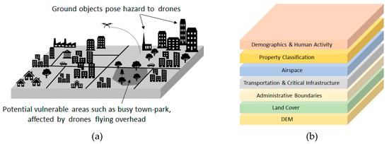
Figure 4.
(a) Hazards and vulnerable objects; (b) geospatial data layers for collaborative urban airspace design.
The research team has taken a pragmatic approach here, based around the premise that only certified drones cleared for operation over urban areas will be allowed to fly over cities and towns. A different approach to addressing ground risk is proposed, which still involves collating relevant datasets, such as topography, airspace, property classification, etc., as shown in Figure 4b. These geospatial datasets are stored on a collaborative cloud-based urban airspace platform, designed by the U-Flyte research team, which enables hazards to drones (e.g., hilly terrain, tall buildings) to be located and identified. Other zones that require permission due to some security or safety concern can also be identified. This digital platform enables all relevant stakeholders, including aviation authorities, municipal councils, city managers, UTM service providers and commercial drone fleet operators, to visualise the VLL airspace and use this collaborative platform, perhaps initially primed with some legislative rules and guidelines, to ultimately decide where/when drones should and should not fly.
The university town of Maynooth (location of the U-Flyte research team) in Ireland, was used as an initial urban UTM test-site. This town is located 25 km west of the capital Dublin, has a population of almost 15,000 and is approximately 3.5 km × 3.5 km in extent, with a train station and busy roads, as well as business-parks, industry hubs and a retail shopping centre. A first step towards developing a model of the airspace that is available and not physically occupied is a high-resolution digital representation of the ground. A digital elevation model (DEM) with a resolution of 1 m was used to build a sufficiently detailed picture of the ground and its permanent features, as shown in Figure 5a.
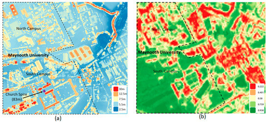
Figure 5.
(a) 1 m resampled Digital Elevation Model (DEM) of Maynooth University town; (b) Normalised Distribution Vegetation Index (NDVI) over Maynooth from Sentinel-2 with vegetated areas in shades of green and the built-environment represented in shades of yellow, orange and red.
Most of the buildings in Maynooth are <10 m in height, with some extending up to 20 m; however, the spire of the university chapel (south campus) extends 83m above ground level. Some aspects to consider when choosing a DEM include the cell dimension, which ideally should be <10 m, and ensuring that the height in that cell represents the highest point within that cell. Some part of the urban DEM may require greater spatial resolution, such as busy take-off/landing zones or more congested downtown areas. The DEM should have been recently acquired (within 1 year) and incorporate additional data sources, such as low-level obstacle databases, usually available from aviation authorities. It is likely that the drones themselves, operating within an urban UTM, will play a key role in updating accurate ground-based data, similar to the concept of self-healing maps proposed for autonomous vehicles. European Copernicus 10 m resolution Sentinel-2 satellite data were acquired and processed to produce a recent Normalised Difference Vegetation Index (NDVI) image-map, as shown in Figure 5b. This image-map distinguishes between vegetated (green) and non-vegetated (yellow, red) areas and is very useful in highlighting open green areas, built environments, water features and road networks.
Additional GIS datasets (e.g., administrative boundaries, land-use, ownership, etc.) can be acquired and, together with DEM and NDVI data, analysed to classify and categorise the urban area into different ground or more detailed land-use classes, as shown in Figure 6a, such as residential, educational, recreational, retail, industrial and transportation. Some of these classes can be further sub-divided (e.g., a residential zone can be further sub-divided into housing and green areas and streets), as shown in Figure 6b.
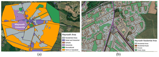
Figure 6.
(a) Maynooth urban area classified into various high-level land-use types; (b) residential sub-classes.
One relatively new data layer that will play an increasingly important role in urban UTM is near real-time human activity. Although demographical data, such as census datasets, are useful, these data are static, representing a single snapshot in time and do not necessarily reflect the patterns of daily activity or what citizens are doing in real-time. The U-Flyte team are currently collating general data protection regulation (GDPR) compliant data from third-party data providers, including mobile phone (e.g., Call Data Records) and personal devices companies, such as the sport and activity tracker Fitbit. These human-activity datasets, some of which are available in near-real time can be aggregated into anonymised, GDPR-compliant activity indicators, that provides very useful spatial-temporal information of human behaviours and patterns associated with typical day-to-day work, school, recreation, sports, retail and travel activities across the city. This aggregated, anonymised activity can be fused with other datasets (e.g., public event databases) to highlight vulnerable zones (e.g., busy outdoor sports venues which might be active in the evenings). Figure 7 details human recreational activity (walking and cycling) around the town of Maynooth and the Maynooth University north campus (in more detail).
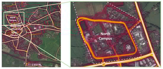
Figure 7.
Aggregated outdoor human activity (walking and cycling), collated by Strava over Maynooth Campus [48].
3.4. Fundamental Building Blocks of Urban Airspace
It is reasonable to expect that most drone trips in urban airspace environments will be at least 1 km in length, overflying tall buildings, infrastructure and trees. It seems more sensible to compute the shortest path for planned drone trips, maintaining level flight wherever possible and avoiding the need to climb or descend in order to avoid obstacles. For this reason, a minimum flying altitude for horizontal flight of 50 m above the chosen vertical datum is proposed. This minimum flying altitude should also help support societally friendly and non-invasive operation, reducing potential privacy concerns and noise pollution. Below this 50 m cut-off plane (base of travel layers), only vertical movement (climb or descend) for take-off and landing is permitted, as shown in Figure 8. This base height value may vary between different cities. This altitude needs to be fixed to an accepted standard vertical height datum, such as barometric QNH, since ground level topography can vary over relatively large city and urban extents. This base-layer altitude can be viewed as a geometric plane that separates the more undulating topography and buildings on the ground from the open airspace higher up. Note that some taller buildings will penetrate this base-layer and 50 m has been initially chosen as a compromise between maximising horizontal flight airspace whilst safe-guarding drones from multi-story buildings, as well as helping address privacy and nuisance concerns.
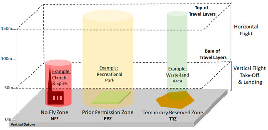
Figure 8.
Schematic detailing base-layer, NFZ, PPZ and TRZ within an urban airspace environment.
A cloud-based, collaborative urban airspace platform has been developed by the U-Flyte team that enables all relevant static and dynamic datasets to be collated, ingested and analysed. A more pragmatic approach has been adopted by the U-Flyte research team concerning ground risk, as outlined in preceding Section 3.2, since it is pervasive within urban environments with real challenges in monitoring and measuring real-time human activity. The emphasis on mitigating risk should switch to ensuring that any drones flying over cities have a high level of operational and safety performance, which can be implemented through a similar process, such as acquiring a certificate of airworthiness, but adapted for urban BVLOS drone operations. Nevertheless, there are still locations or zones on the ground which will have varying levels of permissions in terms of accessibility and operation. Three zone categories have been identified: no fly zones (NFZ); prior permission zones (PPZ); temporary reserved zones (TRZ). These three airspace zones, together with the vertical flight and travel flight layers (base-layer and top-most altitude limit), make-up the accessible airspace over the metropolitan region, as shown in Figure 8.
No Fly Zones (NFZ): In most cities few buildings reach higher than 50 m and a minimum height thus removes most permanent physical structures from interfering with the space for horizontal travel. At the same time, it is true that 50 m is not high enough to exclude all buildings. In this case there still will be zones which physically obstruct the airspace (i.e., it is impossible for a drone to fly through that space and those zones need to be stored as strict no-fly zones within the UTM database), as shown in Figure 8. The DEM layer can be used in conjunction with land-use and property-class data layers to identify NFZ features. It is also worth noting that there are NFZ features that are of a temporary nature, which also potentially pose an obstruction above the 50 m limit. For instance, cranes at a construction site can easily reach a height of 70 to 80 m. Urban airspace NFZ databases will need to be updated on a daily basis or, indeed, as soon as the new obstacle appears on the skyline, a process which could be carried out by the drones themselves.
Prior Permission Zones (PPZ): The drone also poses a risk and is a hazard to everything on the ground in terms of the probability of exposure, vulnerability and severity as it flies above. Prior Permission Zones (PPZ) are zones where, unlike a physical tall building, it is possible to fly into the space, but it may not be desirable, so prior permission is required. Reasons could include safety, security or, indeed, privacy or nuisance concerns. The data layers on this UTM platform, such as property type and human activity can be queried. For example, selecting all green areas that are >1 ha, classified as recreational and have high levels of human recreational activity, can be highlighted. These could then be examined by a UTM airspace designer to determine whether this area is a potential PPZ or not, based on current regulations and guidelines. PPZs could include areas over hospitals which have active helicopter landing pads, prisons or large sports stadiums. So, in the example of the hospital PPZ, general drone traffic would not be allowed to pass through this zone, since it is reserved for Medical Helicopter emergencies by default. However, a drone delivering blood or medical supplies specifically to this hospital could be granted permission to enter the PPZ by the hospital management team. Other examples of PPZs include the airspace over sensitive infrastructure, such as power plants or government buildings where drone traffic could be prohibited for security reasons, but also over vulnerable zones where drone operations could result in substantial damage to valuable infrastructure and injury/fatalities (e.g., airports, pedestrianised streets, large recreational parks or sporting events), as shown in Figure 8.
Furthermore, PPZ can be temporary in nature. For instance, a PPZ could be activated for the duration of a concert at the weekend but then deactivated during weekdays. Different stakeholders and inputs are required to help decide which zones should be designated PPZ in an open and fair manner. The U-Flyte team has developed an online “Mark-up” tool, shown in Figure 9, that enables registered users to search for specific locations and facility types (e.g., “large schools”) overlain on the latest high-resolution satellite or aerial image of the city. The user can then confirm the extent of the PPZ, as well as temporal restrictions (e.g., school only active on weekdays between 8:00 a.m. and 5:00 p.m.).
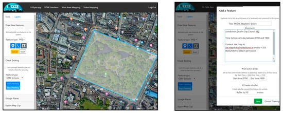
Figure 9.
U-Flyte’s UTM platform Mark-up tool to enable collaborative urban airspace construction.
This ground-based polygon can then be extruded, using the Mark-up tool functions, into a three-dimensional object that covers the airspace above the ground feature, which it aims to protect. The 1-to-1 rule, can be applied in this case, as outlined in the SORA (Specific Operations Risk Assessment) guidelines, which stipulate that, for a drone operating at an altitude of 100 m above the ground, the ground risk buffer should be at least 100 m. This process should be carried out using an intuitive collaborative platform with ready access to relevant geospatial data layers together with national legislation and city regulations, (e.g., a housing association could decide that they do not want high volumes of drones flying over their location, and so establish a PPZ over their housing estate). The initial choice and design of PPZs could be conducted by the appointed UTM service company prior to inviting the wider stakeholder group to participate.
Temporary Reserve Zones (TRZ): Conversely, Temporary Reserve Zones (TRZ) are locations or zones where the exposure and vulnerability on the ground is particularly low, with little or no vulnerable infrastructure and very low levels of human activity on the ground. Examples include enclosed industry zones, brown fields and waste field sites, as shown in Figure 8. TRZs are, therefore, zones where drones could be directed to hover or orbit over, in order to free-up space during an unforeseen external event or in the case of an emergency or malfunction to land. TRZs can be treated in a similar fashion to PPZs but are more likely to be left as open accessible airspace and only flagged as restricted in the event of an emergency. TRZs can be identified and stored using the same online collaborative Mark-up tools, protocols and methodology, as for PPZs.
U-Flyte’s UTM airspace mark-up tool has been developed using scalable cloud-based intuitive interfaces, based around an open source database and geospatial tools, enabling large numbers of stakeholders and users to collaborate and identify candidate NFZs, PPZs and TRZs, check suitability, discuss concerns and find solutions. A key role of this mark-up tool is to ensure that urban airspace, comprising these UTM zones (NFZ, PPZ and TRZ) can be constructed efficiently, as well as in a fair, transparent, democratic manner.
3.5. Urban Airspace Architecture
An urban UTM needs to be able to understand and manage all aspects within the airspace, as these relate to ensuring safe and efficient drone operation. Overall, drone traffic management is influenced by a number of inputs, including assigned mission or aerial task, accessible airspace, existing traffic, as well as overall drone operational performance. The UTM needs to be able to determine an optimum path for a requested trip, assign that track to the drone, track the drone’s progress and intervene in real-time, if necessary, in order to quickly adapt or possibly change the drone’s itinerary. The available or accessible airspace is determined by the operating lower and upper urban airspace limits, together with the three UTM zones—NFZ, PPZ and TRZ. Aspects that need to be considered include the spatial and temporal separation of drones, which should strive to balance safety requirements with operational efficiency. Involving human operators to control drones is not advisable for urban UTM scenarios, which may have to deal with tens and hundreds, if not thousands, of drone movements in an hour over densely populated, high-activity city areas. Having a human operator assigned to each drone on the ground, as well as potentially multiple UTM service providers and associated traffic coordinators, handling or overseeing various requests and instructions, will result in a slow and in-efficient traffic management system or, even worse, possible collisions and serious accidents, as shown in Figure 10. Does the drone operator send a request to one or more UTM service providers for flight slots? Are instructions issued from the UTM service provider to the drone operator who, in turn, manoeuvres the drone?
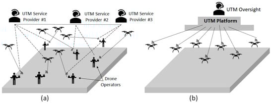
Figure 10.
(a) Multi-operator, multi-UTM service provider scenario; (b) automated urban UTM scenario with drone traffic, coordinated by a UTM platform which is overseen by an UTM director.
It is more advisable to take the human out of the loop—not only the drone operators but also the air traffic coordination function—since it will be more efficient and safer for a machine or digital UTM system to collate all relevant data, consider all inputs, analyse options, compute paths and handle real-time issues, such as potential traffic conflictions, as these arise. These instructions can be issued directly to the drone platform. In effect, the urban UTM platform operates the drone on behalf of the drone operator, but under the watchful eye of the drone operator/fleet managers. In this case the UTM needs to be able to compute a suitable path that avoids all NFZs and PPZs within the system. Secondly, the UTM needs to have a mechanism to avoid paths that have already been allocated to other drones, which may intersect the proposed path at various locations and possibly at the same time. Hence, in order to manage air risk effectively, it is essential that the UTM has full knowledge of all airspace users at any one time. A strategic deconfliction approach is required where the path-finding algorithm is computed for the new drone prior to taking off, to minimize the possibility of interference with other existing flight trajectories. This path is computed and uploaded to the drone before take-off. The path comprises a set of vertices or nodes, along which the drone has to travel, passing through key nodes at pre-set times. This route calculation needs to take into account the drone’s speed profile and current weather conditions, such as head or tail winds.
Note that this process has to handle several competing interests in terms of safety, economy, flexibility and computability that need to be addressed. Safety refers to the spatial separation of the airspace users, economy is choosing the most cost and time efficient routes, flexibility is the ability of the system to make full use of the available airspace and to not be confined by a small number of fixed, predefine routes or corridors, whilst computability means that the system is not overly complex and solutions can be computed in a relatively short time. The spatial nature of the paths should be computed, not only to ensure that these are as direct as possible and without unnecessary heading changes, but to ensure that they are also optimised in terms of travel distance, travel time, arrival time and departure time.
A natural approach to the problem is through the use of a graph network of nodes and edges. Nodes are locations or points where drones are allowed to change direction, while edges are the lines along which drones travel from one node to another. This is akin to the model of a road network comprising streets and crossroads. Nodes and edges can be flagged as un-available at times when they are known to be occupied by a drone or blocked by a NFZ or PPZ, in which case they become unavailable in the path-finding process for the next drones that wish to enter the system. Then, a variation of Dijkstra’s algorithm or an A* algorithm, with respect to the preferred optimisation criteria, can be used to identify an optimal path. The restrictive structure of such a network supports the safety aspect as it introduces an immediate separation between the edges—that is, the places where drones are allowed to travel. Additionally, a pre-defined network structure ensures that the path-finding process is more deterministic and predictable. However, there are obvious drawbacks with a graph network with various advantages and disadvantages in terms of flexibility in path-finding and computational efficiency that will not be detailed here. U-Flyte research has found that key graph requirements of an urban UTM include:
- Efficient pathfinding: the ability to construct a path between any two points in the airspace that is as direct as possible, given the NFZ, PPZ;
- Spatial–temporal separation: any computed path needs to be adequately spatially and temporally separated from all other drones throughout its entire journey;
- Use of the third dimension for deconfliction: given that the possibility of paths intersecting in a busy urban UTM is quite high, the ability to utilise the third dimension is required (i.e., for one of the drones to climb or descend) in order to avoid a traffic conflict.
So, the UTM airspace structure solution proposed by the U-Flyte research team is to create a number of layers (15 m in height) to be stacked vertically from the minimum 50 m lower-level cut-off plane. Assuming an initial urban UTM maximum height of 150 m, this results in three pairs of layers, as shown in Figure 11. Each pair of layers comprises a travel layer for standard transit and a deconfliction layer, which enables a drone to jump over a potential existing path and avoid a traffic conflict.
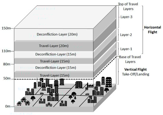
Figure 11.
Schematic of airspace layering structure with three pairs of travel/deconfliction layers.
The length and duration of a drone’s planned trip determines which layer pair the drone is assigned, so short trips are allocated to the lowest of the three travel layers, while medium-distance and long-distance trips are allocated to the middle and upper travel layers, respectively. The aim here is to distribute traffic as much as possible across the layers from the outset and thereby reduce the likelihood of conflict.
3.6. Urban Drone Traffic Management
Four key features of urban drone traffic management, which have been investigated and developed by the U-Flyte research team, are presented in the following sections, including safety tube, strategic deconfliction, tactical deconfliction and emergency event handling
3.6.1. Safety Tube
A drone’s path is a sequence of spatial–temporal nodes, comprising latitude–longitude–altitude coordinates, which the drone has to fly through at a prescribed time. This path is uploaded to the drone prior to take-off and it is the responsibility of the drone to adhere to this path, flying through each given node at the given time. However, drones may not always be able to adhere exactly to the given itinerary. It is apparent that delay is more likely to occur than reaching points ahead of schedule, since it is easier to correct the latter by slowing down if necessary. Delays may be more difficult to correct since these could be caused by a strong headwind, not picked up in an earlier forecast and the drone propulsion’s system may be insufficiently powerful to correct this lost time. Additionally, it is highly probable that a drone will never fly the exact path down to decimetre or, indeed, metre accuracy. Therefore, a spatial and temporal safety margin, or tube, is required for drones to handle these spatial–temporal inconsistencies. An initial examination, based around typical drone dimensions (3 m × 2 m × 2 m), suggests a tube with a radius of 10 m. Furthermore, the tube should be active for at least 15 s before and 60 s after the drone’s scheduled passing. This means, assuming a speed of 20 m/s, the length of the tube is 1500 m, comprising a leading segment of 300 m and a rear segment of 1200 m, as shown in Figure 12.
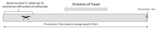
Figure 12.
Drone safety tube—drone is travelling from east to west, with drone located in the forward 20% of the tube, indicating it is on time.
This safety tube cocoons the drone and travels dynamically with the drone as it moves along its path, creating a safety margin of up to 75 s for any point along the planned path. The drone’s ideal location within this safety tube should be in the upper 20% segment (or in the first 15 s of the total 75 s) of the tube. The planned path and real-time location of the drone, together with the accompanying safety tube is logged and it is this dynamic real-time drone safety tube that is treated in a similar fashion to a NFZ. The progress of each drone is monitored by the drone itself, using its onboard flight-controller, and the drone will only alert the UTM if it is in danger of falling behind and exiting this safety tube. The benefit of this approach is that the drone can be left unsupervised if it remains within its safety tube. So, even if the drone were to fall behind by 30 s during its journey, it would not matter to the safety integrity of the system, and so minimal resources need to be spent on constantly checking on the drone’s progress or adjusting its itinerary. The final dimensions of the safety tube are subject to further testing and ultimately depend on characteristics of the Urban UTM and individual drone performance, which are linked to the likelihood of drones being delayed and causes of the delay.
3.6.2. 4D Path-Finding and Strategic Deconfliction
Requests for drone paths may be submitted by drone service providers who have a current approval for Urban UTM operations and suitably certified drones that are registered with that Urban UTM. These requests may be ad-hoc for a one-off trip or scheduled for a later time during the day. Each request is dealt with sequentially and on a first-come-first-served basis. The only exception here might be drones which carry out medical or emergency support functions, which may be pushed-up to the top of the list. In any case, every request is examined with respect to the existing NFZ and PPZ and all other drone journeys, which have been accepted and assigned by the UTM system.
Every request for a new path must contain a start point, an end point and a start time. The distance between the start and end point is used to determine the travel layer the drone is allocated to. Short trips are assigned to the lowest layer, while longer trips are moved further up. So, the first part of the drone’s path is the vertical connection from the take-off point up to the relevant layer. Note how this part of the journey cannot involve any NFZ or PPZ. However, drones that are scheduled to fly right above the take-off point may have to be circumvented. If this is not possible, the departure has to be delayed. At the core of the pathfinding process, we aim to find a suitable path within the relevant layer. We use a classic A* algorithm on an expanding network of possible paths. Initially this network only consists of the direct line from start to end point—as projected into the layer. Next the heuristically most promising path is examined in the current network, with respect to the existing NFZ and PPZ and all other drone journeys which have been accepted and assigned by the UTM system. If no conflict is found, then the path can be accepted as the most suitable path. If, for instance, the direct line from start to end point shows no conflict, then a suitable path has been found, as depicted by the green line in Figure 13.
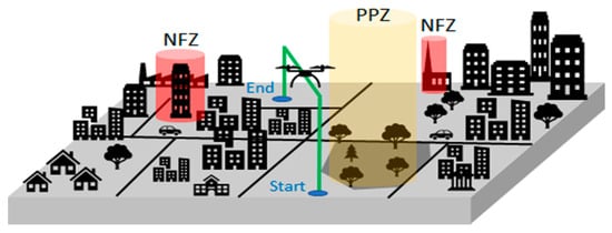
Figure 13.
Schematic of simple drone trip from start to end point—no conflict detected.
If a conflict is returned, then the path is rejected and replaced with alternative paths. The network grows and develops in this way, resulting in more elaborate paths until a trip solution has been found which offers a conflict-free journey from the start to end point. Travel distance is the main cost function, however other heuristics are possible, such as arrival time or travel time, or a more elaborate weighted combination of different indicators.
Two questions remain: “How do we check whether a path is conflict-free?” and “What are the proposed alternative paths if conflict is found?” Recall that a path is a sequence of nodes, beginning with the start point and concluding with the end point. A node in a path is classified as confirmed if the portion of the path from the start point to that node has been established as conflict-free. In this sense the starting node is always confirmed and a path is sought in which the end node is confirmed.
At any stage during the A* process, the heuristically most promising path contains n nodes, where n ≥ 2, and the first i ≥ 1 nodes are confirmed. Given such a path, the pathfinding process aims to confirm the (I + 1)-st node—that is, the edge Ei between nodes i and i + 1 is checked to ensure that it is conflict-free. It is a simple geospatial operation to check whether Ei intersects any of the polygonal NFZ and PPZ of the relevant layer. Furthermore, as the start time and speed of the drone are known, the time the drone is expected to reach node i can be determined. Likewise, the drone’s temporal progression along the edge Ei is known. The database can be queried to check whether Ei intersects the path of any other drone and, if so, whether this spatial conflict is also a temporal one—that is, whether the other drone’s safety tube is active at the relevant time. If no conflicts with the NFZ, PPZ or other drones are found, then node (i + 1) is confirmed and the next subsequent edge is considered. If, on the other hand, conflict is found, then edge Ei and the rest of the path are dismissed.
Conflicts associated with NFZ and PPZ: If the conflict arose from a NFZ or PPZ, then the drone has to be routed around this zone, either to the left or the right of the obstruction. In the case of a building, a third option of flying above the obstacle by climbing temporarily to a higher layer is also available. In the database NFZ and PPZ are stored together with their respective convex hulls. There are at least two ways in which to connect the confirmed portion of the path—that is, the segments from the start node up to node i, with the end node, while also avoiding the NFZ or PPZ. This sequence of edge construction and testing, in order to find an efficient path around the NFZ or PPZ, is detailed in Figure 14.
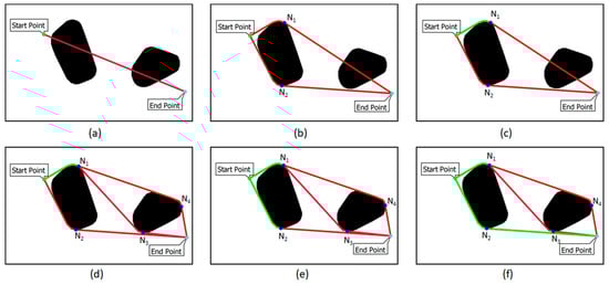
Figure 14.
Strategic deconfliction around NFZ and PPZ objects depicted in 2D plan view; (a) direct line from start to end point is tested—test fails due to first NFZ object; (b) two alternative paths are proposed to lead around the NFZ; (c) upper path is shortest and tested next, edge from start point to node N1 is confirmed and edge from N1 to end point fails due to PPZ object; (d) two alternative paths, connecting N1 to end point, are proposed to lead around PPZ; (e) of the three paths, the lower one is the shortest and is tested next—edge from start point to node N2 is confirmed; (f) edge from N2 to end point is confirmed, thus confirming the entire path.
Conflicts associated with existing drone trajectories: If the conflict arises from another drone in the same layer, then a new node is introduced before the conflict followed by a bridge segment that leads up to the deconfliction layer and descends back down to the travel layer after the other drone’s path has been jumped. Depending on how long the other drone’s safety tube remains active, an alternative path that passes behind, or indeed ahead of the other drone, may be worth considering. Another option, though not currently part of our implementation, is that the speed profile or departure time of the first drone may be adapted to resolve the current conflict in this way. Finally, if a bridge segment cannot be confirmed due to traffic already in the deconfliction layer then nodes that lead around this area of contention are introduced, similar to the NFZ/PPZ case discussed above.
An additional step that checks whether new paths are not unnecessarily circuitous has proven beneficial. Finally, for each new path, the cost function is calculated, and the path is added to the ordered list of all proposed paths, which is then available for the next A* cycle. This algorithm then runs until a path with a confirmed end node has been found. It may not always be possible to end up right above the landing point, due to existing traffic. So, additional pathfinding may be required to ensure that the drone reaches an overhead point which is as close as possible to the target landing zone. Thereafter, it is a more localised problem to ensure the descent circumvents any existing traffic. The final computed path comprises a spatial–temporal sequence of nodes which the drone has to fly through at a prescribed time. The path is uploaded to the drone prior to take-off and it is the responsibility of the drone itself to adhere to this path and timetable. Simultaneously, the path is logged in the UTM database, where it is then available in any subsequent path-finding request.
3.6.3. Tactical (Real-Time) Deconfliction
Real-time traffic conflicts can occur when drones do not remain inside their safety tube whilst traveling along their designated path. This can easily happen if a drone travels slower than expected. Using the example in the preceding section, if the drone only manages a ground speed of 15 m/s, instead of the original 20 m/s, then it falls behind its schedule by 5 m per second. Hence the safety margin provided by the tube’s tail of 1200 m will be exhausted after 240 s, or 4 min, at which point the drone falls out of its safety tube. This causes an immediate problem, since there is now the potential that the slower flying drone inadvertently enters the safety tube of another nearby drone. This gives rise to a potential real-time traffic conflict, so a tactical deconfliction function needs to be triggered in order to handle this situation. This triggering can be instigated by the drone itself, which has been charged to monitor its own progress, but it is likely that the central UTM may also run a secondary drone progress status monitoring process. In this example, the drone monitors its progress and alerts the UTM once its onboard journey monitoring unit records a delay of at least 45 s. At this point the drone is still well within its 60 s tail section and has up to 15 s to remain within the boundary of its safety tube. However, this 15 s period provides a buffer for the UTM to deal with a potential future conflict and issue an updated path with deconfliction instructions. If the drone’s slower progress does not cause a traffic conflict, then the drone’s path can remain unchanged and only its schedule needs to be updated within the UTM. This means the safety tube is delayed by 45 s to ensure that the drone is placed again at the desired 20% position from the front end of the tube. If, on the other hand, the newly computed safety tube is to interfere with another drone’s trajectory, then the UTM must now reroute this drone. This rerouting can be carried out by applying the path-finding algorithm, as described in the previous sub-section, to the remaining part of the journey. The new deconflicted route is then uploaded to the drone as its new itinerary, as well as the UTM central database. The three-image sequence, shown in in Figure 15, describes a simple tactical deconfliction scenario and associated process. In this case, the deconfliction layer is used to jump over the other drone and so resolve the potential traffic conflict.
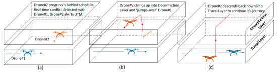
Figure 15.
Tactical deconfliction sequence: orange drone originally operating clear of new blue drone which has just joined UTM, but orange drone is now running behind predicted schedule and alerts UTM (a); UTM examines the paths and instructs delayed orange drone to jump over blue drone in order to avoid traffic conflict (b); orange drone descends back down into travel layer and continues on journey (c).
Requests for real-time deconfliction will also sequentially have to be dealt with by the UTM, and these requests should always be permitted to skip the queue and be processed as soon as possible, given that one key objective of the UTM is to avoid any potential collisions. There should only be a minimal number of requests for real-time deconfliction. However, if this is not the case then the UTM’s pre-flight pathfinding and allocation process requires examination and improvement. The safety tube spatial–temporal dimensions may also need to be adjusted, depending on drone performance, trip durations, as well as the unique characteristics associated with the Urban UTM (e.g., particular daily traffic patterns). The right balance needs to be struck between ensuring safety whilst maximising overall operational efficiency of the urban airspace.
3.6.4. Emergency Event Handling
Emergency events can be classed as either internal or external in nature. Internal emergencies are associated with the drone itself (e.g., engine failure), whilst external events are due to other external factors (e.g., a localised severe weather event which may affect a number of drones over one part of the city).
Internal Event: An internal event might be a situation whereby a drone’s own system experiences a malfunction, which makes it unlikely or impossible for the drone to continue its journey safely. Usually, an emergency of this type will only affect the drone itself, but this depends to a large degree on the type and extent of the damage affecting the drone’s operation. Only licensed drones carrying a current certificate of airworthiness with proven flight performance, together with redundant critical systems, as well as additional on-board safety systems, such as a parachute, should have permission to carry out BVLOS operations within urban airspace. So, the risk of malfunction should be low or, in case of not being able to maintain controlled flight, activate a backup propulsion system or deploy a parachute to support an emergency landing. If the drone is capable of flight, the most expedient route from its current location to a near-by landing zone or Temporary Reserve Zone (TRZ) can be calculated—similar to the tactical deconfliction process, described in sub-Section 3.6.2—and the onboard flight-controller updated with direct itinerary.
External Event: An example of an external event might be a localised weather event or medical emergency helicopter which needs immediate access to the same airspace, occupied by one or more drones, in order to land at a nearby hospital helicopter landing pad. This external emergency event can potentially affect a single drone, or a number of drones, at various locations within the urban airspace volume for differing lengths of time. In the case of an external event involving manned flight, it coordination with conventional Air Traffic Control (ATC) would be required to determine the spatial volume and temporal limits of the emergency airspace that may be required by the medical emergency helicopter. A drone that is already within the emergency zone will need to be given the necessary time to exit along its given route, or if this is deemed too long, be made to return or provided with holding or landing options. Drones which are due to enter the declared emergency zone need to be identified by the UTM and rerouted since this emergency zone is treated as a NFZ for as long as it is active. The UTM will prioritise the affected drones according to their proximity and reroute each one in decreasing order of priority. It might again prove expedient to use a nearby TRZ, clear of the temporary emergency airspace, to reroute the affected drones in order to either hover or land before authorising the drones to resume their journey after the medical emergency helicopter has passed through. Again, all computational aspects of this emergency handling can be dealt with within the above tactical deconfliction framework.
4. UTM: Database Design Considerations and Simulation Results
4.1. Database Design Considerations
The design of the UTM database needs to support the storage and rapid access of both static and dynamic obstacles in order to support real-time 4D drone traffic management. No-fly zones and PPZ can be designed and stored in the database before the system is operated in live mode. However, paths allocated to drones need to be updated to the database in a structured and expedient manner. The database update cycle must ensure that the present drone path is uploaded and stored before the next drone’s path can be computed, since the updated database is used to compute new routes. Additionally, all NFZs, PPZs and TRZs, as well as the latest computed active paths need to be instantly accessible.
Each of the three zone types affects some or all layers of the airspace and at each level the affected region can be represented as a two-dimensional flat surface. Only the corner points of this surface need to be stored as x- and y-coordinates within the respective layer, as shown in Figure 16a. Note how these vertices enable the rapid construction of potential routes around the obstacle during the A* path-finding process, as discussed in the previous section. The key pieces of information for drone paths are the coordinates and associated occupation times associated with each node along the route. Each edge of the path is stored as the quadrilateral safety buffer surrounding it. This captures the spatial component of the edge. In addition, a sequence of points along the edge is stored together with the time interval during which this segment is an active component within the drone’s safety tube and is therefore unavailable to other drones, as shown in Figure 16b. This allows for the rapid checking of potential conflicts when a new drone path is added to the UTM system.
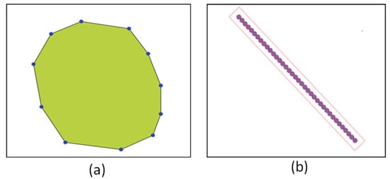
Figure 16.
(a) Extent of a NFZ or PPZ within a layer—only the blue vertices are stored in the database; (b) edge of a drone path—spatial extent is stored by the outer quadrilateral and spatial–temporal components are stored in the points along the edge.
During strategical and tactical deconfliction, it is important to have very fast access to all features which are spatially and temporally relevant to the current requested path-finding operation. In initial experiments, each layer was divided into small cells with a base area of 10 m by 10 m. Then, each cell was marked as either permanently occupied if it occurred in an existing NFZ/PPZ or as temporally occupied, if it contained an existing drone’s safety tube. The availability of an edge during the A* process could be assessed quickly by examining all cells within a 10 m distance of that edge. The edge is rejected even if only one single cell was occupied. Though this works well over a small area, it quickly became apparent that it would not scale for a UTM covering hundreds of square kilometres over a large city. For example, the prototype UTM that was designed by the U-Flyte team over Maynooth covered 3.5 km by 3.5 km of urban area. This resulted in a manageable 122,500 cells per layer, or 735,000 cells across the six layers when using 10 m × 10 m cells. However, for a relatively small European city, such as Dublin (115 km2), this results in 1.15 million cells per layer, or a total of nearly 7 million cells over the six layers.
The use of larger cells and an associated lower number of queries was investigated. However, as cells increase in size, more area is unnecessarily declared as occupied by a single drone, as shown in Figure 17a. On the other hand, every edge needs to be checked against all NFZ, PPZ and drone trajectories in the database during the A* process, in the absence of a suitable reference mechanism. So, the U-Flyte research team devised a compromise where each layer in the airspace (travel and deconfliction layers) is divided into cells of 500 m × 500 m. Each of these 500 m × 500 m cells stores a reference to every NFZ, PPZ and drone trajectory that intersect the cell, as shown in Figure 17b. In addition, the temporal extent of the intersection for drone trajectories is also stored.
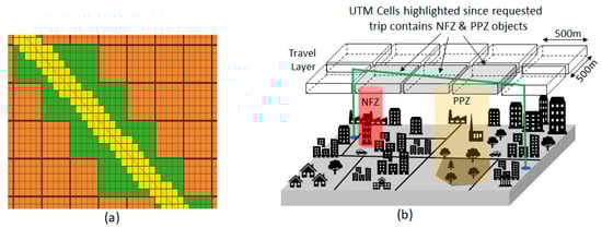
Figure 17.
(a) Yellow area represents all 10 m by 10 m cells within 10 m of line and green area represents all 50 m by 50 m cells within 10 m of line; (b) Schematic of 500 m × 500 m UTM cells used as a spatial index for rapid database searching.
So, during the path computation process, a candidate edge is checked against the features of all the cells it passes through. This is usually a spatial test for NFZs and PPZs, and a spatial–temporal test in the case of drone itineraries as we check whether the edge intersects the other trajectory at a time when the intersection is part of drone’s safety tube. In general, it is expected that each 500 m × 500 m cell contains no more than a handful of NFZs and PPZs and a small number of drone trajectories during the relevant short time interval in which the new drone plans to travel. The 500 m by 500 m cell size appears to be a reasonable compromise between the amount of checking required per cell and the overall number of cells that need to be stored. This database structure can be relatively easily scaled-up to handle large city and urban areas. For example, a city of 30 km × 30 km results in a total of 3600 UTM cells per layer. This totals 21,600 UTM cells, assuming six layers. Additionally, storing a drone path is relatively inexpensive. Note that every path has to be linked to the cells it encounters. However, a typical path of 5 km length will affect no more than between 10 to 20 UTM cells. In effect, this 500 m × 500 m UTM cell acts as a spatial–temporal index, dramatically reducing the time for search and retrieval during the path-finding process. The computational efficiency of these 500 m × 500 m cell sizes with city-scale UTM databases is still undergoing performance assessment.
Open Source Computing Modules
The U-Flyte research team has completed the design and construction of the airspace and traffic management simulator using various Open Source components. The simulation system’s front-end and back-end are primarily developed using NodeJS with Express framework, an open source JavaScript runtime environment which excels at concurrent operations and speed of HTTP request handling, as shown in Figure 18. The client-facing globe itself is created using CesiumJS, an open source Javascript library with powerful functionality for building 3D geospatial visualisations.
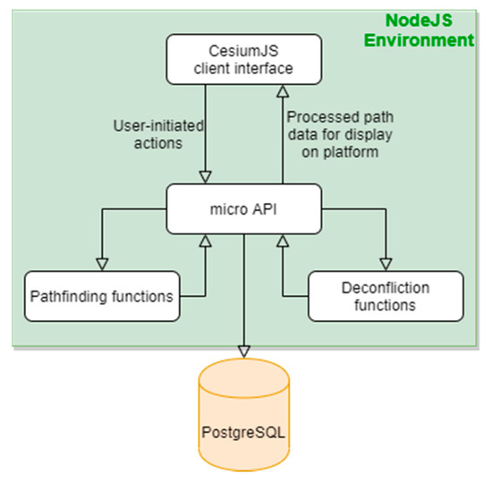
Figure 18.
Schematic overview of Simulation components.
Pathfinding and deconfliction services are implemented using Python, a functional programming language with notable performance benefits regarding searching and sorting large amounts of data. The NFZ, PPZ and TRZ zone datasets are stored on a remote PostgreSQL database, geospatially enabled with PostGIS extension. A micro API handles requests between these different elements of the server. A user viewing the CesiumJS interface can initiate the simulation and deconfliction events. These actions trigger API requests, which perform the relevant database connections and requests to pathfinding functions.
4.2. U-Flyte’s UTM Simulator
A prototype UTM simulator was designed and constructed over the town of Maynooth, covering an area of 3.5 km by 3.5 km. A base reference altitude of 50 m above ground level (AGL) was chosen, under which only vertical or transitioning flight was allowed. The AGL datum was chosen in this case, since the area is relatively small and uniformly flat. Six vertical layers, 15 m in vertical extent, comprising three pairs travel and deconfliction layers were stacked on top of this 50 m base reference layer. The deconfliction layer was used to enable a drone jump over, another potential conflicting drone path. As described in the previous section, the UTM cell size was fixed at 500 m × 500 m, resulting in 49 UTM cells per layer and a total of 294 UTM cells across all six layers. One NFZ was identified—that is, the chapel spire on the university campus. A further four PPZs were established, all of which covered school areas. No TRZs were designed for this relatively small urban area. A list of 400 path requests was compiled, prior to running the simulation, with the only constraints being that no point should fall under a NFZ or PPZ and every start/end pair had to be at least 100 m apart. All resulting pairs had a varying separation distance of between 100 m to 4500 m. Launch time requests were allocated at 2 s intervals to all pairs. This resulted in an 800 s (just over 13 min 20 s) period between the first and last drone launch, Figure 19. Finally, drone speed was set at 15 m/s (54 km/hr). The simulation was initiated with the upload of the entire list of 400 path requests to the UTM, in order of requested starting time. So, this resulted in the path requests and computations, in similar order to their departure schedule. Origin/Destination pairs with a distance of up to 1200 m were allocated to the lowest travel layer, while pairs with a distance of up to 2400 m and above were allocated to the middle and top travel layer, respectively. Note that, as take-off and landing were not simulated, potential conflict arising from climbing or descending to/from the travel/deconfliction layer were not taken into account between the three pairs of travel and deconfliction layers.
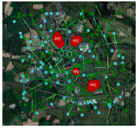
Figure 19.
The output of U-Flyte’s UTM simulator at one moment during the 800 s during which drones took-off. We see a snapshot of 65 airborne drones and their given paths from their start points (green) to their end points (cyan). Note that, in this top down view, it is not possible to distinguish the layer at which each drone operates.
The 400 requests were computed by the UTM in just under 30 s. Of those, 316 trips were computed in less than 0.1 s each. The remaining 84 trips required a computation time of up to 0.45 s each. Furthermore 116 paths were allocated to layer-pair 1, 164 to layer-pair 2 and 120 to the top-most layer-pair 3. A total of 102 trips did not encounter any NFZ, PPZ or other drone paths, while a further 25 did not encounter any other drone. In the case of 60 drones, each had to use the deconfliction layer once, twice or three times. A further 90 drones had to carry out the manoeuvre between four and six times, with the remaining half a dozen drones having to avoid another trajectory on seven occasions. Currently, drones are instructed to return from the deconfliction layer back down to the travel layer as soon as the conflict in the travel layer has been overflown. In future fine tuning, closely located tactical deconfliction manoeuvres, affecting the one drone, will be merged into one longer tactical deconfliction manoeuvre. Early path-finding requests are computationally less demanding, as there are still very few drone trajectories in the system against which new paths need to be deconflicted. However, with the current simulation, 60 drones were scheduled to be airborne at any instant, from the 75th request onwards. It was estimated that up to 20 other active, existing drones were examined for potential conflict in any of the layer pairs, since these were spread more or less evenly across the three layer pairs (travel and deconfliction layers).
Computation times typically increase with increasing UTM complexity in terms of the number of drones requesting paths, the lengths of the trips and the numbers of NFZ, PPZ and other drones that are in the system. A journey of 20 km is more likely to have to route around several NFZ, PPZ and several other drone trajectories, and so will require additional computation time. Computational improvements include general path-finding processes which favour finding a solution quickly instead of consuming valuable computation time searching for marginally better solutions.
This initial simulation suggests that this airspace architecture, coupled with a traffic management system, has the scope to handle several hundreds of drones, all of which seek to use an airspace of just over 12 km2 at one point over a time interval of around 15 min. Many path requests faced a traffic density of at least two drones per square kilometre. Assuming three layer pairs for a city the size of Dublin (115 km2), this is equivalent to nearly 700 drones evenly spread around the airspace at any one instant. This approach has the potential to scale-up in order to manage airspace and traffic for much larger, busier cities and urban environments in terms of database size, pathfinding and deconflictions. The vertical layer structuring lends itself to parallel computing, where a different machine could be assigned to a particular vertical layer pair, speeding up path finding and tactical deconfliction. Moreover, various sections over a city could be handled by different machines as long as the trips requested were not spatially co-located. For example, two 5 km path requests, one over the north-east and the other over the south-west of a 20 km wide city could be dealt with in parallel by two different machines at the same time.
5. Research Outputs and Conclusions
Operating drones over urban environments presents, perhaps, the greatest challenges to the drone industry, due to the ever-pervasive human activity found in cities and towns, coupled with the likely demand for hundreds, if not thousands, of drone services per hour. Although great strides have been made in the operation of drones over the last decade, we are perhaps, no closer to the rollout of BVLOS drone operations over urban environments than we were five years ago. There are several areas that need to be addressed to make this happen, including the drone flying platform itself, reliable navigation, communications and monitoring technologies, which are all at various stages of development and readiness.
One area that would seem to be within our grasp, yet remains elusive, is the formulation of the best approach for structuring urban airspace architecture in order to manage large volumes of traffic. Despite the best efforts of national and international UTM initiatives, it still remains unclear as to how these urban airspace systems should be designed and operated. Shortcomings include vague and sometimes incomplete collections of frameworks, architectures, systems, methodologies and operational protocols. This stalemate has probably come about due to the sheer number of stakeholders that need to be involved in this process, including civil aviation regulatory agencies, air traffic control operators, technology companies and municipal authorities, as well as civil societies. The net impact has been a more fragmented approach to how urban UTM systems are designed, constructed and operated, with some topics being developed without any due regard to other inputs or outputs (e.g., a traffic management system without an airspace architecture). Other impacts include the inefficiencies and sometimes wasted efforts in large numbers of research and technology groups attempting to solve the same problem. In some cases, these technology groups just want to develop and commercialise a service (e.g., parcel delivery), but then end up attempting to solve the urban UTM puzzle, yet again.
The fundamental contribution of this paper is addressing this current shortcomings in urban UTM design and highlighting the need to make the connection between urban airspace modelling and the associated traffic management system. This has been achieved by examining the fundamental elements of urban UTM and devising pragmatic methodologies for modelling airspace as well as scalable traffic management solutions. The main findings, contributions and conclusions are listed in following sub-sections.
5.1. Chief Findings and Outputs
The U-Flyte research team has researched and reported on its initial efforts focused on investigating the fundamental elements underpinning an urban UTM, together with associated prototype airspace modelling and traffic simulation, carried out over the Maynooth urban area in Ireland.
5.1.1. Contribution 1: Urban Airspace Modelling
Key geospatial datasets were identified and described in the first stage of urban airspace modelling, including DEM, land-use, GIS, and human activity. These data inputs were used in the second stage to develop a collaborative, cloud-based Urban Airspace design tool, enabling upper/lower airspace limits to be set together with no-fly (NFZ), prior permissions (PPZ) and temporary reserve (TRZ) zones. The third and final stage involved designing a computational graph (node-edge) network that facilitates rapid pathfinding within urban airspace, arranged in three vertical layer pairs, comprising travel and deconfliction layers, which incorporate the NFZ, PPZ and TRZ objects, bounded by upper and lower airspace limits.
5.1.2. Contribution 2: Prototype Urban Traffic Management System
The team developed four key features to enable traffic management for drones in busy urban environments, including a safety tube, strategic tactical deconfliction and emergency management. The safety tube maximises safety whilst minimising UTM monitoring resources and ensures that drones can still move across the city when traffic loadings are high. Strategic and tactical deconfliction functions were developed to compute both pre-flight (strategic) and in-flight (tactical) paths in tens of milliseconds, based on the underlying airspace graph (node-edge) with in-built optimisation. An emergency management protocol was presented, detailing how both internal (e.g., propulsion malfunction) and external (e.g., police helicopter) events could be handled over urban areas.
5.1.3. Contribution 3: Prototype Urban Airspace Simulation System
An urban UTM simulator was developed based on the airspace model and traffic management engine described in preceding paragraphs. The simulator’s performance was assessed using 400 randomly chosen drone journeys within a typical urban airspace (NFZ, PPZ), 3.5 km × 3.5 km in size and extending vertically to 120 m AGL. Pathfinding, using strategic deconfliction for the entire fleet of 400 drones took just under 30 s to compute. Each of the drones were launched at arbitrary 2 s intervals on trips ranging from 100 m to 4500 m in distance. All 400 drones were successfully launched (simulation mode) in 800 s (13 min 20 s). Traffic conflicts were detected and handled for a large number of these trips across the three pairs of vertical layers (travel and deconfliction), with an average traffic density of 2 drones per square kilometre, suggesting that a city the size of Dublin (115 km2) could handle nearly 700 drones evenly spread around the airspace at any one instant using our current simulator.
5.2. Conclusions
Urban airspace modelling and traffic management system development are intrinsically 4D (real-time) in nature and these two functions should be interlinked to ensure the development of a more robust, safely operated, efficient UTM platform. Anonymized and dynamic human activity will play a central role in the comprehensive modelling of risk and, perhaps more pertinent in time, overflight permissions in urban regions. A more pragmatic approach to addressing urban airspace modelling would incorporate a collaborative cloud-based airspace design tool, which has the added bonus of facilitating all stakeholders who can be brought together and thus promote a more democratic design of accessible airspace above our towns and cities. Airspaces over cities and towns come in different shapes and sizes but require fundamental geospatial information regarding how risk and permission zones can be structured in order to facilitate optimised drone traffic management.
Fundamental aspects of traffic management include the concept of a safety tube for individual drone trajectories, strategic and tactical confliction, as well as how emergency events can be handled. Drones that fly in urban airspace should require the equivalent of a certificate of airworthiness with minimum requirements set to address flight operational performance and safety features over densely populated areas. Urban UTM platforms need to be able to handle, not only potentially large volumes of VLL airspace, but also very high traffic loadings with increasing pressure from drone service providers for airspace access and prioritisation. The underlying database design, coupled with airspace architecture graph and trajectory management algorithms, need to be able to scale and adapt to these increasing pressures. Open Source, open standards and open data, together with a more detailed framework for designing and building urban UTM, would greatly accelerate the roll-out of these much need infrastructures. Direct human input in busy urban UTM operations, whether this is a drone operator or traffic management function, should be minimal. These flight operational activities need to be carried out by a machine with human input and interaction confined to a higher-level oversight role. Finally, VLL urban airspaces, outside of busy airport airspace, need to be controlled by the UTM sector.
Author Contributions
Funding acquisition, resources, writing—original draft preparation, supervision, project administration, T.M.; conceptualization, investigation, methodology, formal analysis, writing—review and editing, T.M. & L.P.; software, validation, visualisation, L.P., R.B. and T.M. All authors have read and agreed to the published version of the manuscript.
Funding
This publication has emanated from research supported by a Strategic Partnership Programme Grant from Science Foundation Ireland, in association with Airbus and Irelandia Aviation, under Grant number 17/SPP/3460.
Conflicts of Interest
The authors declare no conflict of interest.
References
- Mogili, U.R.; Deepak, B.B.V.L. Review on application of drone systems in precision agriculture. Procedia Comput. Sci. 2018, 133, 502–509. [Google Scholar] [CrossRef]
- Congress, S.S.; Puppala, A.J.; Lundberg, C.L. Total system error analysis of UAV-CRP technology for monitoring transportation infrastructure assets. Eng. Geol. 2018, 247, 104–116. [Google Scholar] [CrossRef]
- Ogan, R.T.; Lott, D.; Paden, W. Electrical Transmission Line Inspection using Unmanned Aircraft. In Proceedings of the 2019 SoutheastCon, Huntsville, AL, USA, 11–14 April 2019; IEEE: Piscataway, NJ, USA, 2019. [Google Scholar]
- Besada, J.A.; Bergesio, L.; Campaña, I.; Vaquero-Melchor, D.; López-Araquistain, J.; Bernardos, A.M.; Casar, J.R. Drone mission definition and implementation for automated infrastructure inspection using airborne sensors. Sensors 2018, 18, 1170. [Google Scholar] [CrossRef] [PubMed]
- Yanmaz, E.; Yahyanejad, S.; Rinner, B.; Hellwagner, H.; Bettstetter, C. Drone networks: Communications, coordination, and sensing. Ad. Hoc. Netw. 2018, 68, 1–16. [Google Scholar] [CrossRef]
- Karaca, Y.; Cicek, M.; Tatli, O.; Sahin, A.; Pasli, S.; Beser, M.F.; Turedi, S. The potential use of unmanned aircraft systems (drones) in mountain search and rescue operations. Am. J. Emerg. Med. 2018, 36, 583–588. [Google Scholar] [CrossRef] [PubMed]
- Ackerman, E.K.M. The blood is here: Zipline’s medical delivery drones are changing the game in Rwanda. IEEE Spectrum 2019, 56, 24–31. [Google Scholar] [CrossRef]
- Estrada, M.A.R.; Ndoma, A. The uses of unmanned aerial vehicles–UAV’s-(or drones) in social logistic: Natural disasters response and humanitarian relief aid. Procedia Comput. Sci. 2019, 149, 375–383. [Google Scholar] [CrossRef]
- Thipphavong, D.P.; Apaza, R.; Barmore, B.; Battiste, V.; Burian, B.; Dao, Q.; Idris, H.R. Urban air mobility airspace integration concepts and considerations. In Proceedings of the 2018 Aviation Technology, Integration, and Operations Conference, Atlanta, GA, USA, 25–29 June 2018. [Google Scholar]
- Hasan, S. Urban Air Mobility (UAM) Market Study. 2019. Available online: https://ntrs.nasa.gov/search.jsp?R=20190026762 (accessed on 19 June 2019).
- Bulusu, V.; Sengupta, R. Urban Air Mobility: Viability of Hub-Door and Door-Door Movement by Air. 2020. Available online: https://escholarship.org/uc/item/6wq6x800 (accessed on 27 April 2020).
- Aurambout, J.P.; Gkoumas, K.; Ciuffo, B. Last mile delivery by drones: An estimation of viable market potential and access to citizens across European cities. Eur. Transp. Res. Rev. 2019, 11, 30. [Google Scholar] [CrossRef]
- Kyrkou, C.; Timotheou, S.; Kolios, P.; Theocharides, T.; Panayiotou, C. Drones: Augmenting our quality of life. IEEE Potentials 2019, 38, 30–36. [Google Scholar] [CrossRef]
- Financial-Times. Drones. How the Commercial Drone Market Became Big Busines. 2019. Available online: https://www.ft.com/content/cbd0d81a-0d40-11ea-bb52-34c8d9dc6d84 (accessed on 27 April 2020).
- Bloomberg. Global Drone Market to Reach $70B by 2029. 2019. Available online: https://www.bloomberg.com/press-releases/2019-05-30/the-global-unmanned-aerial-vehicle-uav-market-to-reach-to-70-28-billion-by-2029 (accessed on 27 April 2020).
- Otto, N.; Agatz, J.; Campbell, B.G.; Pesch, E. Optimization approaches for civil applications of unmanned aerial vehicles (UAVs) or aerial drones: A survey. Networks 2018, 72, 411–458. [Google Scholar] [CrossRef]
- NASA. UTM Concept of Operations V2.0. 2020. Available online: https://utm.arc.nasa.gov/docs/2020-03-FAA-NextGen-UTM_ConOps_v2.pdf (accessed on 27 April 2020).
- Duffy, J.P.; Cunliffe, A.; DeBell, L.; Sandbrook, C.; Wich, S.A.; Shutler, J.D.; Anderson, K. Location, location, location: Considerations when using lightweight drones in challenging environments. Remote Sens. Ecol. Conserv. 2018, 4, 7–19. [Google Scholar] [CrossRef]
- Bassi, E. European Drones Regulation: Today’s Legal Challenges. In Proceedings of the 2019 International Conference on Unmanned Aircraft Systems (ICUAS), Atlanta, GA, USA, 11–14 June 2019. [Google Scholar]
- Winkler, S.; Zeadally, S.; Evans, K. Privacy and civilian drone use: The need for further regulation. IEEE Secur. Priv. 2018, 16, 72–80. [Google Scholar] [CrossRef]
- Molina, M.D.R.d.; Campos, V.S. Ethics and Civil Drones: European Policies and Proposals for the Industry; Springer: Berlin/Heidelberg, Germany, 2018. [Google Scholar]
- SESAR. European Drone Outlook Study: Unlocking the Value for Europe. 2016. Available online: https://www.sesarju.eu/sites/default/files/documents/reports/European_Drones_Outlook_Study_2016.pdf (accessed on 27 April 2020).
- FAA. FAA Aerospace Forecast. 2020. Available online: https://www.faa.gov/news/updates/?newsId=93646 (accessed on 27 April 2020).
- Doole, M.; Ellerbroek, J.; Hoekstra, J. Drone delivery: Urban airspace traffic density estimation. In Proceedings of the 8th SESAR Innovation Days, Salzburg, Austria, 3–7 December 2018. [Google Scholar]
- UN. UN Statistics. 2019. Available online: https://unstats.un.org/sdgs/report/2019/goal-11/ (accessed on 27 April 2020).
- Johnson, M.; Jung, J.; Rios, J.; Mercer, J.; Homola, J.; Prevot, T.D.M.; Kopardekar, P. Flight test evaluation of an unmanned aircraft system traffic management (UTM) concept for multiple beyond-visual-line-of-sight operations. USA/Eur. Air Traffic Manag. Res. Dev. Semin. 2017, 1–10. [Google Scholar]
- Vidović, T.M.; Wang, B.; Štimac, I. OPERATIONS OF DRONES IN CONTROLLED AIRSPACE IN EUROPE. Int. J. Traffic Transp. Eng. 2019, 9, 38–52. [Google Scholar]
- SESAR. Supporting Safe and Secure Drone Operations in Europe. 2020. Available online: https://www.sesarju.eu/sites/default/files/documents/u-space/U-space%20Drone%20Operations%20Europe.pdf (accessed on 27 April 2020).
- Pérez-Castán, J.A.; Comendador, F.G.; Cardenas-Soria, A.B.; Janisch, D.; Valdés, R.M.A. Identification, Categorisation and Gaps of Safety Indicators for U-Space. Energies 2020, 13, 608. [Google Scholar] [CrossRef]
- Eurocontrol. European Netowrk of U-Space Demonstrators. 2020. Available online: https://www.eurocontrol.int/product/european-network-u-space-demonstrators (accessed on 27 April 2020).
- SESAR. SESAR U-Space Demonstrators. 2020. Available online: https://www.sesarju.eu/news/uspacedemonstrators (accessed on 27 April 2020).
- JARUS. JARUS and SORA. 2020. Available online: http://jarus-rpas.org/content/jar-doc-06-sora-package (accessed on 27 April 2020).
- Labib, N.S.; Danoy, G.; Musial, J.; Brust, M.R.; Bouvry, P. Internet of Unmanned Aerial Vehicles—A Multilayer Low-Altitude Airspace Model for Distributed UAV Traffic Management. Sensors 2019, 19, 4779. [Google Scholar] [CrossRef] [PubMed]
- Brittain, M.; Wei, P. Autonomous Air Traffic Controller: A Deep Multi-Agent Reinforcement Learning Approach. 2019. Available online: https://arxiv.org/pdf/1905.01303.pdf (accessed on 27 April 2020).
- Doole, M.; Ellerbroek, J.; Hoekstra, J.; Mennella, A.; Onate, M. Drone Information Service Requirements for U-Space. In Proceedings of the 8th SESAR Innovation Days, Salzburg, Austria, 3–7 December 2018. [Google Scholar]
- Acevedo, J.J.; Castaño, Á.R.; Andrade-Pineda, J.L.; Ollero, A. A 4D grid based approach for efficient conflict detection in large-scale multi-UAV scenarios. In Proceedings of the 2019 Workshop on Research, Education and Development of Unmanned Aerial Systems, Cranfield, UK, 25–27 November 2019; IEEE: Piscataway, NJ, USA, 2019. [Google Scholar]
- Peinecke, N.; Kuenz, A. Deconflicting the urban drone airspace. In Proceedings of the 2017 IEEE/AIAA 36th Digital Avionics Systems Conference (DASC), St. Petersburg, FL, USA, 17–21 December 2017; IEEE: Piscataway, NJ, USA, 2017. [Google Scholar]
- Lundberg, J.; Palmerius, K.L.; Josefsson, B. Urban Air Traffic Management (UTM) Implementation In Cities-Sampled Side-Effects. In Proceedings of the 2018 IEEE/AIAA 37th Digital Avionics Systems Conference (DASC), London, UK, 23–27 September 2018; IEEE: Piscataway, NJ, USA, 2018. [Google Scholar]
- Primatesta, S.; Cuomo, L.; Guglieri, G.; Rizzo, A. An innovative algorithm to estimate risk optimum path for unmanned aerial vehicles in urban environments. Transp. Res. procedia 2018, 35, 44–53. [Google Scholar] [CrossRef]
- Primatesta, S.; Rizzo, A.; la Cour-Harbo, A. Ground risk map for unmanned aircraft in urban environments. J. Intell. Robot. Syst. 2020, 97, 489–509. [Google Scholar] [CrossRef]
- Ippolito, C. Dynamic Ground Risk Mitigation for Autonomous Small UAS in Urban Environments. In Proceedings of the AIAA Scitech 2019 Forum, San Diego, CA, USA, 7–11 January 2019. [Google Scholar]
- Holden, J.; Goel, N. Uber Elevate: Fast-Forwarding to a Future of On-Demand Urban Air Transportation. 2016. Available online: https://www.uber.com/elevate.pdf (accessed on 27 April 2020).
- Geister, D.; Korn, B. Concept for Urban Airspace Integration. 2017. Available online: https://www.dlr.de/fl/en/PortalData/14/Resources/dokumente/veroeffentlichungen/Concept_for_Urban_Airspace_Integration.pdf (accessed on 27 April 2020).
- Airbus. Airbus UTM Blueprint. 2018. Available online: https://storage.googleapis.com/blueprint/Airbus_UTM_Blueprint.pdf (accessed on 27 April 2020).
- Watkins, S.; Burry, J.; Mohamed, A.; Marino, M.; Prudden, S.; Fisher, A.; Kloet, N.; Clothier, R. Ten questions concerning the use of drones in urban environments. Build. Environ. 2020, 167, 106458. [Google Scholar] [CrossRef]
- IAA. Drone Regulations. 2020. Available online: https://www.iaa.ie/general-aviation/drones (accessed on 27 April 2020).
- EASA. Proposed Means of Compliance with the Special Condition VTOL Issue-1. May 2020. Available online: https://www.easa.europa.eu/sites/default/files/dfu/proposed_moc_sc_vtol_issue_1.pdf (accessed on 27 April 2020).
- Strava. Strava Global Heat Map. 2018. Available online: https://www.strava.com/heatmap#7.00/-120.90000/38.36000/hot/all (accessed on 27 April 2020).
© 2020 by the authors. Licensee MDPI, Basel, Switzerland. This article is an open access article distributed under the terms and conditions of the Creative Commons Attribution (CC BY) license (http://creativecommons.org/licenses/by/4.0/).