Article

Interface Failure of Heated GLARETM Fiber–Metal Laminates under Bird Strike

Designing Plastics and Composite Materials Department, Montan University, 8700 Leoben, Austria
Aerospace 2020, 7(3), 28; https://doi.org/10.3390/aerospace7030028
Submission received: 2 February 2020 / Revised: 7 March 2020 / Accepted: 10 March 2020 / Published: 17 March 2020
(This article belongs to the Special Issue Crashworthiness Design for Aviation Safety)

Abstract

:
Many high-strength composite materials have been developed for aircraft structures. GLAss fiber REinforced aluminum (GLARE) is one of the high-performance composites. The review of articles, however, yielded no study on the impact damage of heated GLARE laminates. This study, therefore, aimed at developing a numerical model that can delineate the continuum damage of GLARE 5A-3/2-0.3 laminates at elevated temperatures. In the first stage, the inter-laminar interface failure of heated GLARE laminate had been investigated at room temperature and 80 °C. The numerical analysis employed a three-dimensional GLARE 5A-3/2-0.3 model that accommodated volumetric cohesive interfaces between mating material layers. Lagrangian smoothed particles populated the projectile. The model considered the degradation of tensile and shear modulus of glass fiber reinforced epoxy (GF/EP) at 80 °C, while incorporated temperature-dependent critical strain energy release rate of cohesive interfaces. When coupled with the material particulars, an 82 m/s bird impact at room temperature exhibited delamination first in the GF/EP 90°/0° interface farthest from the impacted side. Keeping the impact velocity, interface failure propagated at a slower rate at 80 °C than that at room temperature, which was in agreement with the impact damage determined in the experiments. The outcomes of this study will help optimize a GLARE laminate based on the anti-icing temperature of aircraft.

1. Introduction

1.1. Impact Damage

Laminated composites are prone to damage when they encounter low-energy impacts, e.g., bird strikes and hailstones [1,2,3]. The frequent damage has undermined to some extent the potential of composite materials, although, their high stiffness, strength-to-weight ratio, good fatigue resistance, corrosion resistance, and formability are appreciable. The impact damage of composite materials appears in dissimilar modes, to name a few, delamination, fiber breakage, and matrix cracks. In most low velocity impact events, the nonvisible damage of composite laminates can be a concern [4], as it can grow depending on the future load spectrum.

1.2. GLARE

By contrast, the impact damage of GLAss fiber REinforced aluminium (GLARE) cannot go undetected attributed to the visible dents in the ductile outer aluminum (Al) skin. GLARE is a laminated fiber/metal composite and comprises alternating S2-glass fiber reinforced epoxy-FM94 composite laminates and Al 2024-T3 alloy sheets. The advantages of GLARE manifest in its excellent fatigue tolerance, high impact resistance, and lightening behavior [5]. Each Airbus A380 has about 380 m2 GLARE in the upper fuselage [6,7]. Strides have been taken to elaborate the thermal functions of GLARE, in particular, to assist aircraft de/anti-icing. At the anti-icing temperature, e.g., 80 °C [8,9], the strength and the stiffness of GF/EP degrade [10], though the ductility of epoxy inclines [11]. Low velocity bird impacts, as a result, are believed to alter the impact resistance of GLARE at an elevated temperature. Yet, the ductile epoxy should delay the inter-ply failure by plasticizing the inter-laminar interfaces. The merits of these conjecture need to be interrogated before drawing a conclusion.

1.3. Existing Knowledge

Numerous studies have shown that the extent of composite delamination reduces at an elevated temperature. For example, the spectra/epoxy composites delaminate to a lower extent at 100 °C [12]. Because, the delamination energy augments twofold when the temperature reaches +100 °C from −50 °C [12]. Levin et al. [13] found a lower extent of delamination in carbon fiber reinforced epoxy (CF/EP) composites, when impacted at a test temperature of 70 °C. Hot-wet exposures combined with a frequent temperature change (−55/+80 °C) exacerbate the damage in composites [14,15,16], though, reinforce the delamination resistance by increasing the fracture toughness of resin [11,17,18,19].
Meanwhile, researchers have reported opposite trends, wherein an elevated temperature reinforced the delamination of composite laminates. Karasek and coworkers have identified a decrease of the incipient load of CF/EP at 66 °C [20,21,22], which triggered early delamination. Conversely, e-glass/epoxy unidirectional laminates (first, eight times hygrothermally conditioned: alternately in room temperature water and in an oven at 100 °C; next, subjected to 12.8 J impact) accumulated excessive transverse matrix cracks and pronounced delamination [23]. Because, microvoids formed [24,25] and the inter-laminar shear strength showed a drop [26,27,28,29].

1.4. Critical Strain Energy Release Rate

Efforts have been made to characterize the properties of inter-laminar interfaces of various composite laminates at dissimilar temperatures. Quasi-static experiments at 80 °C have demonstrated an increase of critical strain energy release rate (CSERR = Gc) of S2-glass/FM94-epoxy and E-glass/araldite laminate interfaces [10,30]. End notch flexure (ENF) tests on CF/EP (HTA/6376C) composites resulted in an increase of GIIc at 100 °C [31]. In conformity, a test temperature of 90 °C enhanced the GIc of a symmetric [0°]16/s CF/EP (AS4/3501-6) laminate attributed to the fiber bridging and ductility of epoxy [32], even though, degraded the GIc of XN1244 adhesive [33]. CF/EP (IM7/8552) laminates, in a four-point quasi-static bending test at 80°C, showed an increase of Gc by 39% compared to that at room temperature [34]. Similarly, GIc of unreinforced epoxy-3501-6 increased by 27% when the temperature inclined from −50 to +100 °C [35], due to the fact that the fracture evolved to be stable and ductile, and the failure locus shifted to the adhesive interface [36]. The overall outcomes depicted the increase of CSERR of epoxy interfaces at an elevated test temperature.
Noting the temperature as well as the strain rate, the fiber direction of mating composite plies, and the crack length impact the inter-laminar interface properties, a higher strain rate raises the least threshold of GIc of CF/EP (AS4/3501-6) composites [37], while a 0°/0° laminate interface is tougher than a 0°/90° interface [38]. As a crack grows, Gc exceeds its initial magnitude to reach a plateau that characterizes a steady crack propagation [39,40,41].

1.5. Next Leap

Despite research having been pursued to interogate the effects of high strain rate, elevated temperature and mismatch of fiber orientation on the inter-laminar interfaces of black composites [42], the coupled effect of these three particulars on the failure of GLARE inter-laminar interfaces has attracted no attention. As far as the author’s knowledge is concerned, the impact damage of GLARE inter-laminar interfaces at an elevated airborne temperature had not been investigated before. Against this backdrop, this study envisaged to investigate such an impact event by implementing a three dimensional (3D) finite element (FE) model of GLARE 5A-3/2-0.3, which incorporated 3D cohesive zone elements (CZEs) between mating material layers. The numerical analysis replicated a bird strike on a GLARE panel at a high strain rate. Smoothed particle hydrodynamics (SPH) particles populated the simplified projecile (bird-analog). The SPH meshless formulation allowed large deformation of the projectile. The model could approximate the breach of GLARE inter-laminar interfaces by taking the fiber orientation of adjacent plies, temperature-dependent material properties and strain-rate of material in consideration. In companion, the low velocity impact experiments exhibited continuum damage in correspondence to the predicted ones, which demonstrated the reliability of the numerical model.

2. Modeling Particulars
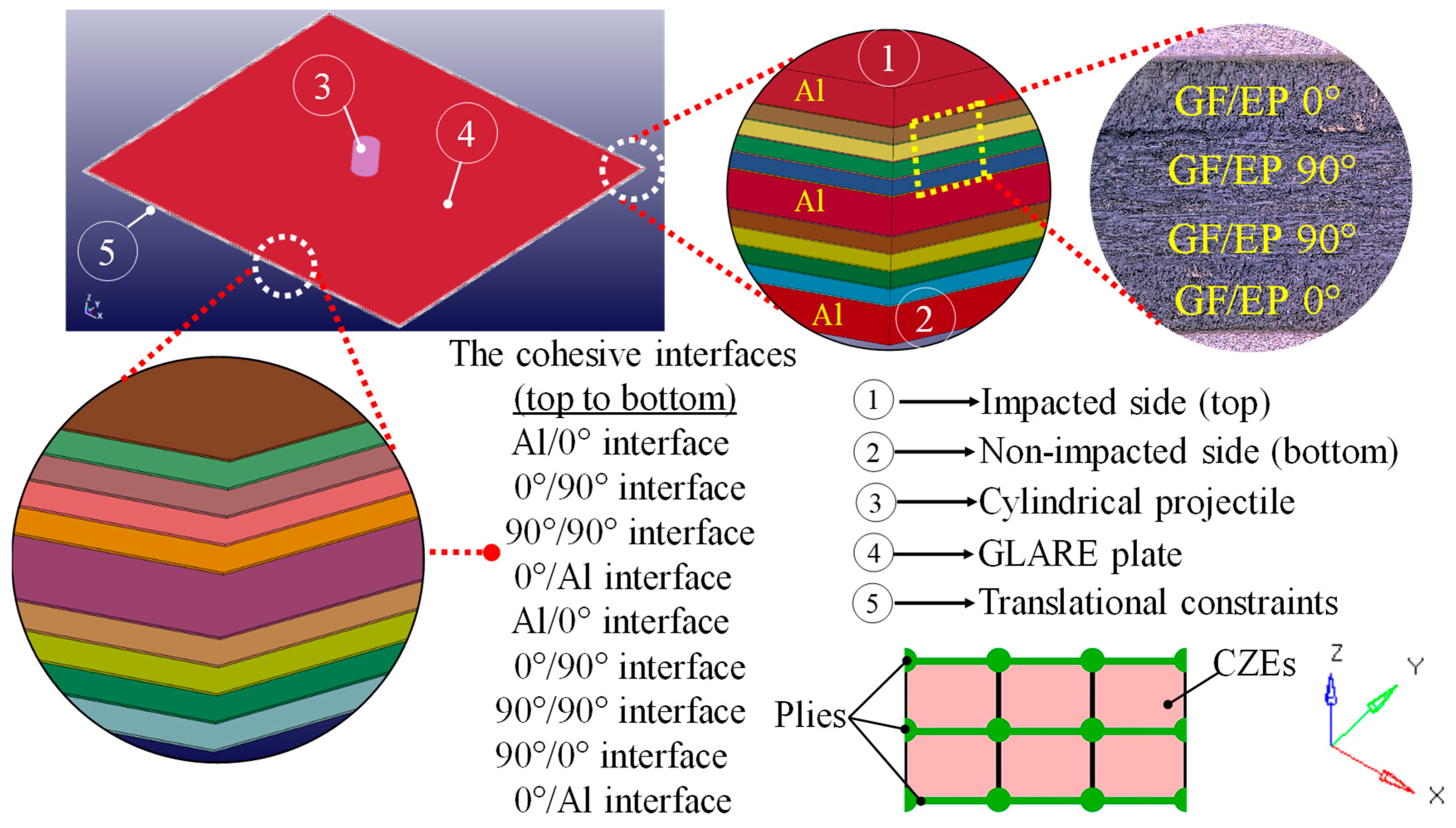
2.1. Geometry

3D CAD software CATIA V5 furnished the sketch of GLARE geometry. The commercial mesh generator HYPERMESH 11.0 was implemented to discretize the geometry. The explicit nonlinear finite element (FE) code LS-DYNA accommodated the FE model of GLARE 5A-3/2-0.3 grade. This cross-ply GLARE configuration was preferred, because it is optimized for structures likely to experience impact loads [43,44]. The stacking sequence [Al/0°/90°/90°/0°/Al/0°/90°/90°/0°/Al] incorporated material layers of in-plane dimension of 2000 × 2000 mm. Respectively, 0.3, 0.125, and 0.01 mm thick Al-layers, GF/EP-plies, and cohesive interfaces comprised the GLARE thickness of 1.9 mm. The cohesive elements were placed between consecutive volume elements of the material layers with nodal coincidence. Figure 1 demonstrates the GLARE laminate and its cohesive interfaces between the mating material layers.

2.2. Discretization

A unique element set discretized each Al-layer and GF/EP-ply. Total 395,032 full integrated Lagrangian solid elements discretized the GLARE laminate. Keeping the interfacial strength, the finer CZEs fail faster [45]. The tendency is opposite when the CZEs are coarser [45]. This non-physical effect of discretization tailbacks to the parameters govern the damage initiation of a cohesive element. Trial and error convinced the author to implement an element size of 15 × 15 mm, which offered a smooth stress gradient and an intermediate failure rate of cohesive interfaces. It is worth mentioning that this element size is relevant for the geometry, the material, the boundary and the loading conditions specified in this study. Through the thickness, one solid element per GF/EP ply and per interface allowed a layerwise discretization. The solid elements of Al-layers and GF/EP-plies had eight nodes and one integration point, while eight nodes and four integration points charcterized the cohesive elements. Density per unit volume delineated the mass of cohesive elements.
7.86 × 10⁵ Lagrangian discrete particles populated the flat faced cylindrical projectile of dimension 63 mm (radius (Rb)) × 152 mm (length (Lb)) (Figure 2). The cylindrical projectile emulated a simplified bird. Numerous studies have validated the cylindrical projectile as a bird-analog for a bird strike analysis [46,47,48].

2.3. Material Properties

2.3.1. GLARE Material

Table 1 and Table 2 include the mechanical properties of a unidirectional GF/EP-ply and Al-layer. The composite damage material card_022 accommodated the mechanical properties of S2-glass/FM94-epoxy composite plies. The piecewise linear plasticity material card_024 incorporated the strain-rate dependent plasticity of Al. Figure 3a,b illustrate the plastic response of Al layer to a tensile stress at different strain rates at room temperature and 80 °C. Tensile stress regime was chosen, since tension promotes crack initiation. The tensile strength of Al was circa 5 MPa lower at 80 °C than that at room temperature for the same strain-rate. Figure 3a,b, therefore, look nearly alike. The pre-assigned plastic response of Al at different strain rates allowed the numerical code to extrapolate the plastic behavior of Al layers for a beyond threshold strain-rate. It is to notice that the dissipated impact energy in GLARE differs by less than 1.5% when residual curing stresses exist in GLARE [49]. This analysis, in accordance, neglected the minor influence of residual thermal stress on the impact resistance of GLARE. The material properties outlined in Table 1, Table 2 and Table 3 are taken from an in-house technical report, which has not been made available for public release.

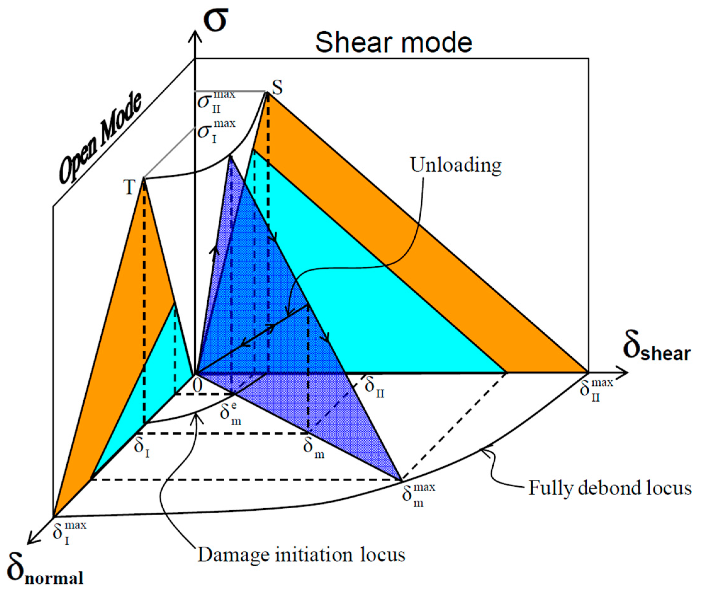
2.3.2. Cohesive Zone Material

The cohesive mixed-mode material card_138 incorporated the material properties of FM94-epoxy of the CZEs [51]. In line with the literature [52], the stiffness and the strength of FM94-epoxy were decreased with the temperature increase, while the CSERR of FM94-epoxy was increased. Table 3 shows the properties of CZEs at room temperature and 80 °C.

2.3.3. Projectile Material

The null material card_009 accommodated the material properties of the projectile. The projectile volume 1.9 × 106 mm3 and the projectile density 9.38 × 10⁻⁷ kg/mm3 resulted in the projectile mass (mp) of circa 1.8 kg. The projectile material emulated gelatin, which had a dynamic viscosity coefficient of 4 × 10⁻⁹. The constitutive law of homogeneous fluidic gelatin reads [53]
σ i j = P δ i j + 2 ρ γ e ˙ i j ,
where the stress tensor, the pressure, and the Kronecker delta symbol are σij, P, and δij, respectively; the dynamic mass density, the strain, and the strain rate tensor are ρ, γ, and ėij, respectively.
The material properties of projectile evolved with the dynamic fluid pressure. The thermodynamic equation of state (EOS) concatenated the fluid pressure (P) with the natural logarithm of volumetric strain (εv) and internal energy (E) of projectile [48,53] (see Equation (2)). Here, C is the compression modulus of gelatin. Since the temperature (T) change of gelatin was unlikely in low velocity impact events, two state-variables (C and εv) defined the EOS (see Equation (3)).
P = C ( ε v ) + γ T ( ε v ) E ,
P = C ( ε v ) ,
The compression modulus followed the relative volume of the projectile, as assigned by the tabular EOS in Table 4. C increased at the phase of projectile fragmentation.

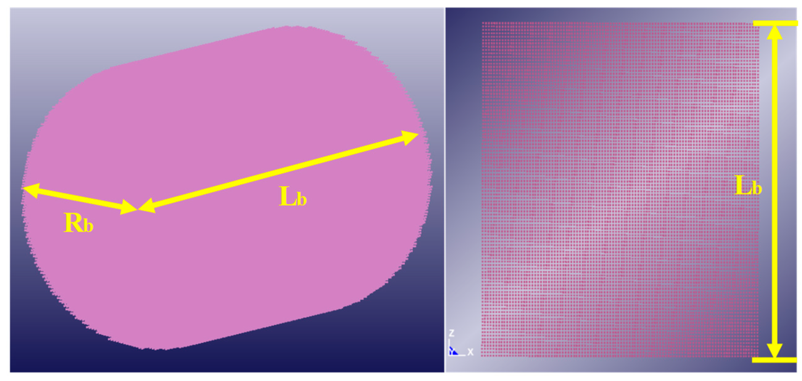
2.4. Projectile Hydrodynamics

The projectile acted as a fluid domain of moving particles. The SPH kernel evenly dispersed the projectile mass among the constituent particles. Each particle replicated an interpolation point, where the hydrodynamic and the thermodynamic fluid properties were updated in each computation cycle. The analysis scheme interpolated the fluid properties from one particle to the neighbor ones located within a spatial distance, i.e., smoothing length. The smoothing length reads [54]
h = σ ( m i ρ i ) 1 / d
where h is the smoothing length; σ and d are the volumetric stress and the three dimensions of the projectile; mi and ρi are the mass and the density of a particle denoted as i. The computation cycles updated the density of particles as a function of the compression modulus of gelatin, making the smoothing length time-dependent.
A smoothing kernel collected the updated smoothing length in each time step and implemented a cubic spline interpolation function to interpolate the particle properties within the smoothing length. The smoothing kernel (W) was defined as [55]
W ( x i x j , h ) = 1 h θ ( x i x j h )
where θ is the incidence angle of the projectile relative to the normal of the GLARE front surface; xi and xj are the spatial positions of neighboring particles within the smoothing length. The constituent hydrodynamic particles of the projectile were described by [55]
( x i ( t ) , m i ( t ) ) t p
where xi(t) and mi(t) are the time-dependent spatial position and mass of a SPH particle; P in the subscript is the set of moving particles. Temporal evolution of the particle mass in the impact phase and the rebound phase was computed from [54]
d m i d t = V ( x i , t ) m i
where, V is the velocity of the ith particle.
The mass conservation of SPH particles was inferred from [54]
d ρ d t ( x i ) = j = 1 N m j ( V ( x j ) V ( x i ) ) W i j

2.5. Constitutive Equations

2.5.1. GF/EP Composites

The analysis presumed GF/EP-laminates linear elastic in mechanical behavior, according to the findings in [56,57]. For the sake of brevity, the numerical framework did not contemplate the composite damage mechanism, since only inter-laminar interface failures were in the focus of this study. To account for the through-thickness deformation, the constitutive equation of a GF/EP ply was orthotropic, for which the stress–strain relationship in the incremental form was [58,59]
[ Δ σ 11 Δ σ 22 Δ σ 33 Δ τ 23 Δ τ 31 Δ τ 12 ] = [ C 11 C 12 C 13 0 0 0 C 21 C 22 C 23 0 0 0 C 31 C 32 C 33 0 0 0 0 0 0 C 44 0 0 0 0 0 0 C 55 0 0 0 0 0 0 C 66 ] [ Δ ε 11 Δ ε 22 Δ ε 33 Δ γ 23 Δ γ 31 Δ γ 12 ]
where, x, y = 1, 2, 3 are the material directions; Δσxy and Δεxy are the stress increment and the strain increment, respectively; Cxy is the stiffness coefficient. The X-axis (fiber direction) and the Y-axis (transverse-fiber) of a unidirectional GF/EP ply were oriented, respectively, in the 11-direction and the 22-direction. The global Z-axis followed the 33-direction, i.e., the through-thickness direction.

2.5.2. Cohesive Zone

A bilinear traction-separation law governed the failure of cohesive zones both in the peel mode and the shear mode [60], see Figure 4. Damage initiated in the cohesive element given that the total mixed-mode relative displacement ( δ m 0 ) was satisfied [61,62]
δ m 0 = δ I 0 δ I I 0 1 + β 2 ( δ I I 0 ) 2 + ( β δ I I 0 ) 2
δ I 0 = T / E N and δ I I 0 = S / E T denote the displacements to onset the interface failure in mode-I (normal only mode) and mode-II (shear only mode). The ratio of mode mixity (β) is expressed by
β = δ I I 0 δ I 0
β was assumed as 0.2, which meant 16.66 % contribution of GIIc to the total Gc. This assumption is appropriate for an impact load on laminated composites [63,64], however, is load-case specific.
When the interface failure initiated, two different approaches were implemented to determine the linear softening and the critical (maximum) mixed-mode displacement, at which the cohesive element entirely failed. The power law determined the critical mixed-mode displacement ( δ m max )
δ m max = 2 ( 1 + β ) 2 δ m 0 [ ( E N G I c ) X M U + ( E T G I I c ) X M U ] 1 X M U
when XMU > 0; where XMU resembles the fracture toughness of the resin interface. If XMU < 0, the Benzeggagh-Kenane law computed δ m max from [62,65]
δ m max = 2 δ 0 m ( 1 1 + β 2 E N + β 2 1 + β 2 E T ) [ G I c + ( G I I c G I c ) ( β 2 E T E N + β 2 E T ) | X M U | ]
where EN and ET are the normal and the tangential stiffness of epoxy resin, respectively; T and S are the peak traction in the normal direction and the shear direction, respectively; GIc and GIIc are the CSERR in the corresponding directions.

2.6. Boundary Conditions

2.6.1. Translational Constraints

Clamps at the edges prevented the rigid body motion of the GLARE panel. A stand-off distance of 8 mm defined the initial gap between the projectile and the GLARE panel. The projectile was launched with an impact velocity (VI) of 82 m/s at an incidence obliquity of 0° related to the normal of the GLARE surface. The 0° angle of attack (AoA) made sure the most transfer of projectile momentum to the GLARE panel. The general landing speed of passenger aircraft is 82 m/s [66], which was employed as the projectile velocity to reconstruct a bird strike event.

2.6.2. Projectile/Target Interaction

An automatic node-to-surface contact defined the interaction between the projectile and the GLARE panel. The contact setting SOFT 1 prevented the penetration of SPH particles in the GLARE surface by updating the contact stiffness based on the global time step size and the nodal mass. The projectile/target interaction was presumed frictionless as contact friction is not discernible at a high strain rate of gelatin projectile [25].

2.7. Numerical Implementation

The reference frame of numerical analysis coupled Lagrangian and SPH methods, because they did not involve many derivatives in iteration [67]. For the sake of simplicity, the numerical model did not include the fiber breakage and the matrix cracks of GF/EP plies, thus, eliminated the computational complexity, which arises due to distorted Lagrangian elements. A time step size of 0.01 ms satisfied the convergence criterion of Courant–Friedrichs–Lewy (CFL ≤ 1). Hourglass control type-6 was chosen to prevent the non-physical zero-energy degrees of freedom of adherends after the failure of cohesive elements [68].

3. Computational Predictions

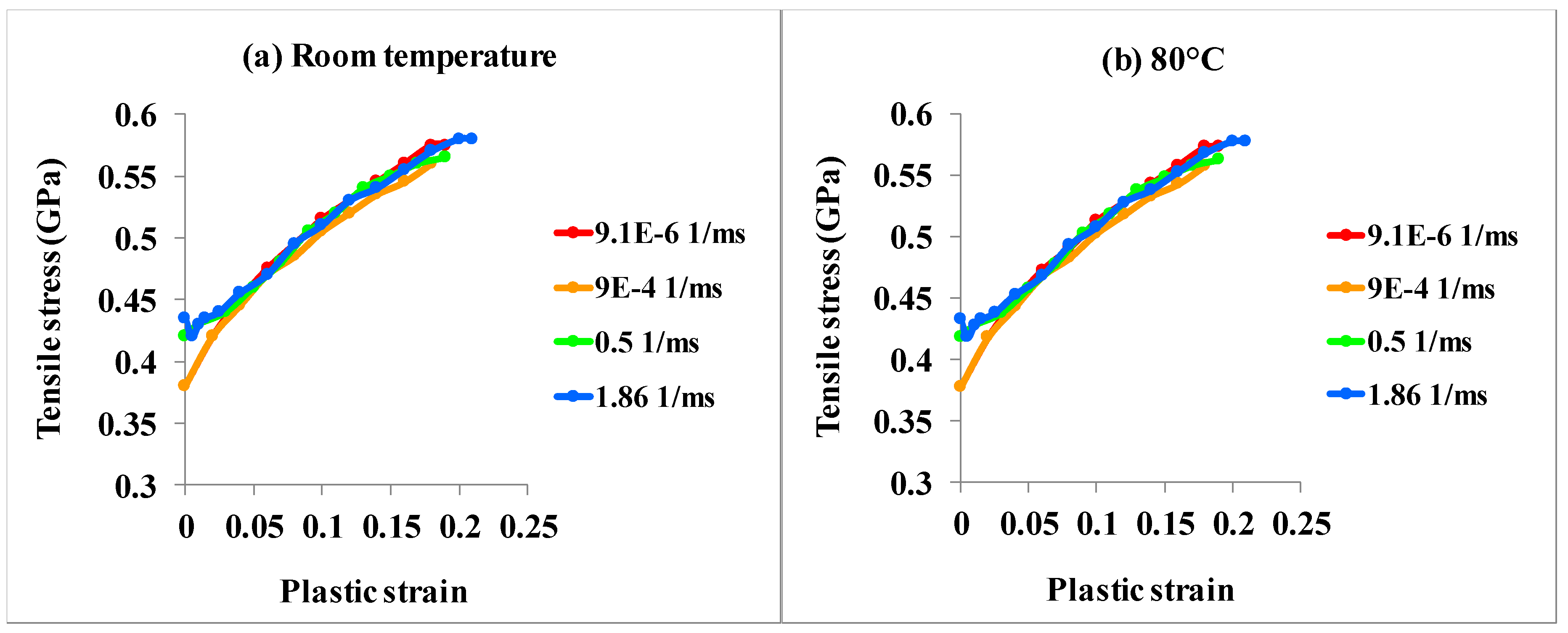
3.1. Elastoplastic Response of GLARE

Low velocity impact on a GLARE laminate induces multiple delamination through the laminate thickness [44,64,69]. Posterior to impact loading, the delamination area, the axisymmetry and the thickness of generated sub-laminates decide the post-damage buckling behavior of the disintegrated laminate under compression [70]. Thicker sub-laminates possess a higher bending stiffness. Similarly, the impact analysis of GLARE at room temperature and 80 °C predicted debonding/delamination-induced sub-laminates of dissimilar thickness, which will be discussed in the upcoming discourse.

3.1.1. Room Temperature (Gc0)

Figure 5 exemplifies the response of GLARE laminate to the impact energy of 6.051 kJ. The impact energy resulted from the mp = 1.8 kg and the VI = 82 m/s of the gelatin projectile. The impact response of GLARE corresponded to the properties of material and cohesive interface at room temperature.
The stress wave traversed the GLARE panel at a velocity of 4.754 km/s ascribed to the GLARE bulk modulus of 32.97 GPa, which was derived from the elastic modulus at room temperature. The stress wave reverberated at the rear surface (non-impacted side). Since the stress wave got released at the inter-laminar interfaces and the critical stresses of the Al/GF/EP-0° and the GF/EP 90°/0° interface were reached, the entire GLARE laminate disintegrated into sub-laminates within the impact zone (Figure 5b). Besides, a lower Gc at room temperature, compared to that at 80°C, allowed a faster propagation of interface failure towards the GLARE periphery (Figure 5d–e). As seen in Figure 5f, multiple interface failures enveloped the impact zone, because the mismatch of bending stiffness of sub-laminates reinforced the mode-I (normal mode) interface loading.

3.1.2. Model Verification

To corroborate the outcomes of bird impact analysis, the delineated predictions at room temperature were assessed qualitatively using comparable experimental results published in open literature. Yaghoubi et al. [64] investigated the low velocity impact damage of GLARE 5-3/2-0.3 laminate at room temperature. The 101.6 × 101.6 mm specimens were manufactured from S2-glass fiber reinforced epoxy and Al 2024-T3 alloy. The square specimens were clamped in a fixture, leaving an open circular area of 76.2 mm diameter. Next, a hemispherical steel projectile of 16 mm diameter and 12.91 kg mass was dislodged to exert 30 J impacts on the clamped specimens in a drop-weight impact tower.
In a complementary study, Chen et al. [71] conducted low velocity impact experiments on GLARE 5-3/2-0.25 specimens at room temperature. The GLARE laminate was manufactured from S4-glass fiber reinforced epoxy plies and Al 2024-T3 alloy sheets. The 150 × 100 mm rectangular specimens were clamped in a steel fixture with a cutout of 125 × 75 mm. Next, a solid spherical head of 16 mm diameter and 5.36 kg mass was dislodged in a guided drop-weight tower to impart 70 J energy to the clamped specimens. These two independent experimental campaigns exhibited delamination of the GF/EP-90°/0° interface farthest from the impacted side, which agreed with the prediction of the numerical analysis of this study (see Figure 6).
Looking at the differences, the projectile of numerical analysis was fluidic gelatin by contrast to the rigid metal projectiles used in the selected experimental studies. On the other hand, the impact energy in numerical analysis was two orders of magnitude higher than that of the experiments. The rigid projectiles of experiments displayed no deformation upon impact. However, the fragmentation of gelatin dissipated a large amount of impact energy, which otherwise would have been allocated to the impact damage of GLARE. The numerical prediction, therefore, was in fair agreement with the experimental results.

3.1.3. 80 °C (Gc80 = Gc0 + (39%*Gc0))

Keeping the impact energy at 6.051 kJ, Figure 7 exhibits the impact response of GLARE laminate for the material and interface properties at 80 °C (see Table 1, Table 2 and Table 3). The analysis considered a 39% increase of Gc of cohesive interfaces at 80 °C compared to Gc0 at room temperature, as recommended in [34].
At 80 °C, the velocity of stress wave in GLARE declined to 4.388 km/s, since the bulk modulus of GLARE degraded to 28.08 GPa at 80 °C. Upon impact, the peel and the shear strength of cohesive interfaces were not exhausted, as a result (Figure 7b). Next, the progressive bending deformation of GLARE reinforced the inter-laminar stresses beyond the failure limit, leading to the onset of GF/EP 90°/0° and 0°/90° interface delamination (Figure 7c). In the successive time steps, the delamination grew at a slower rate in the lateral direction (Figure 7d–f) ascribed to the higher Gc of cohesive interfaces at 80 °C. Because of no mismatch angle between mating plies, the shear stress was the least in the GF/EP 90°/90° interface, which accumulated namely the lowest extent of failure. At 0.14 ms, these two inter-ply delaminations divided the GLARE laminate into three sub-laminates.

3.1.4. 80 °C (Gc80 = Gc0 + (45%*Gc0))

Compared to the findings in [34], the author determined through DCB and ENF experiments a 45% increase of Gc of cohesive interfaces at 80°C relative to that at room temperature. To assess the influence of tougher inter-laminar interfaces on the integrity of GLARE laminate, a third analysis was executed by implementing the updated GLARE constituent properties. Applying the identical impact energy, the GLARE deformation and the interface delamination were akin to that exhibited in Figure 7. The onset of delamination surfaced at the same instance (0.12 ms). The delamination growth was very much alike. Furthermore, the sub-laminates were comparable to the sub-laminates of the preceding analysis in terms of thickness and stacking sequence, despite the tougher cross-ply interfaces (as were in this case) appeared to be more associative with the accommodating plies. Due to the slim difference of GLARE deformation for the explicated tougher interface, the pictorial images are not repeated here.

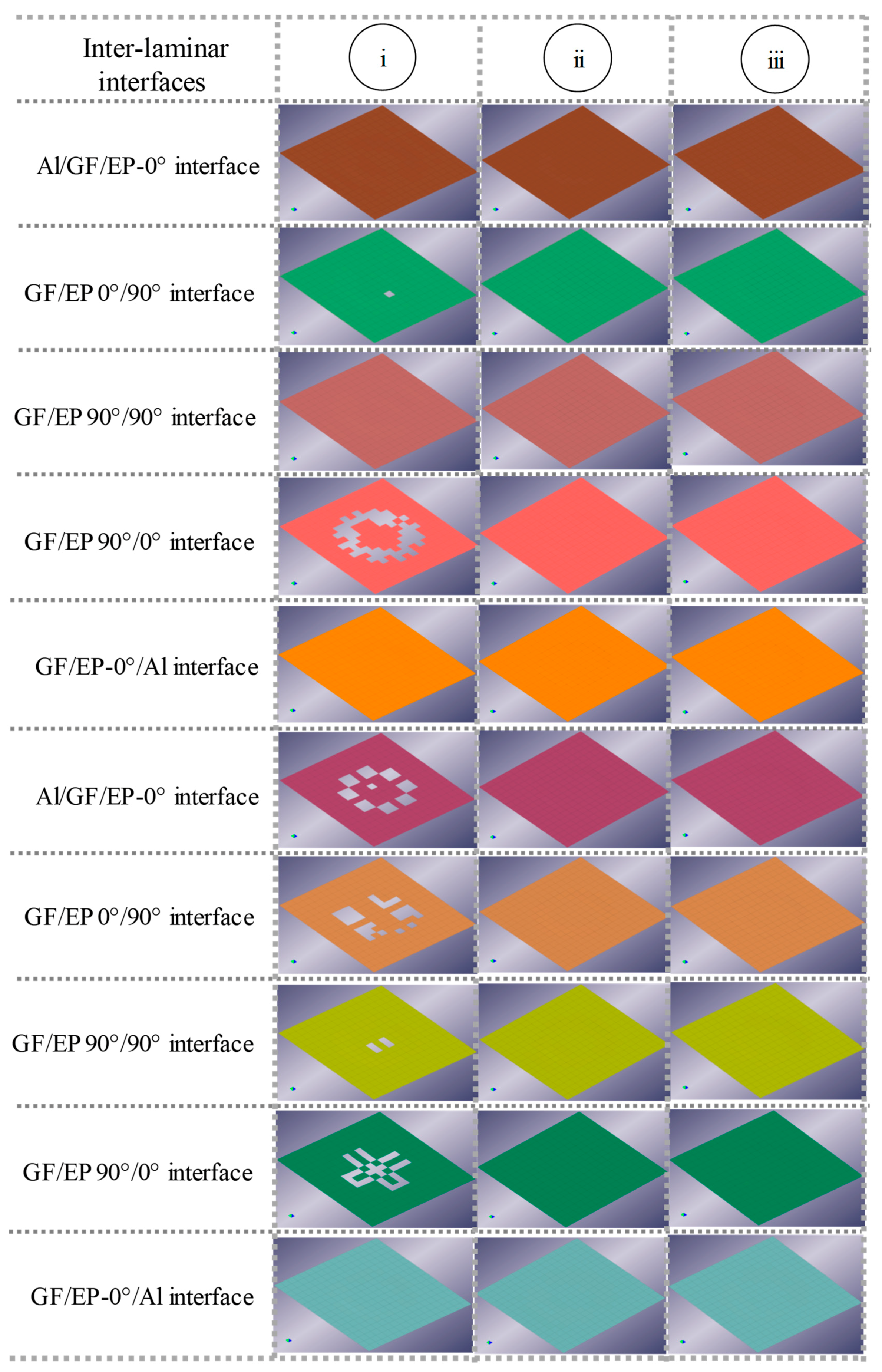
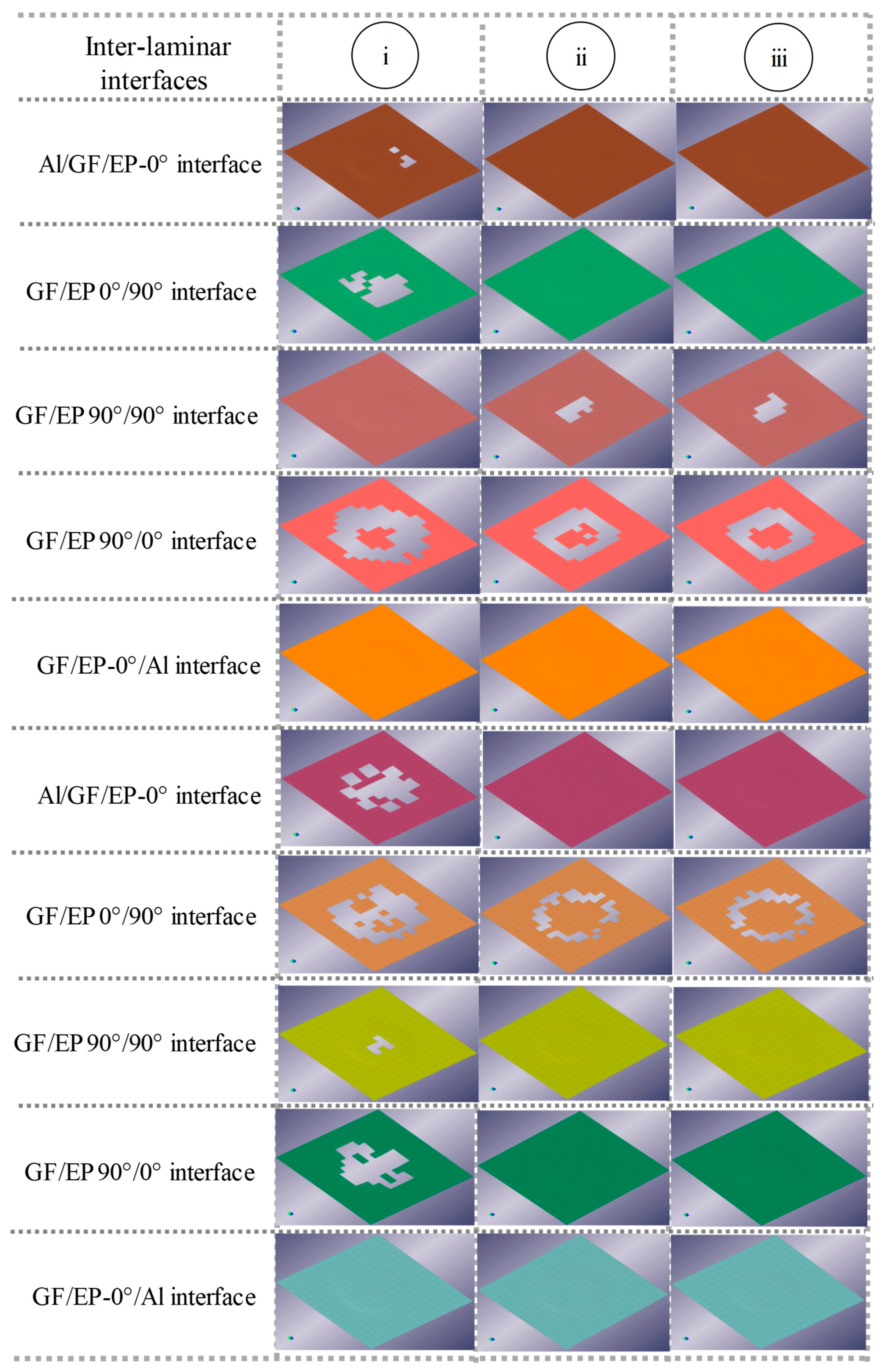
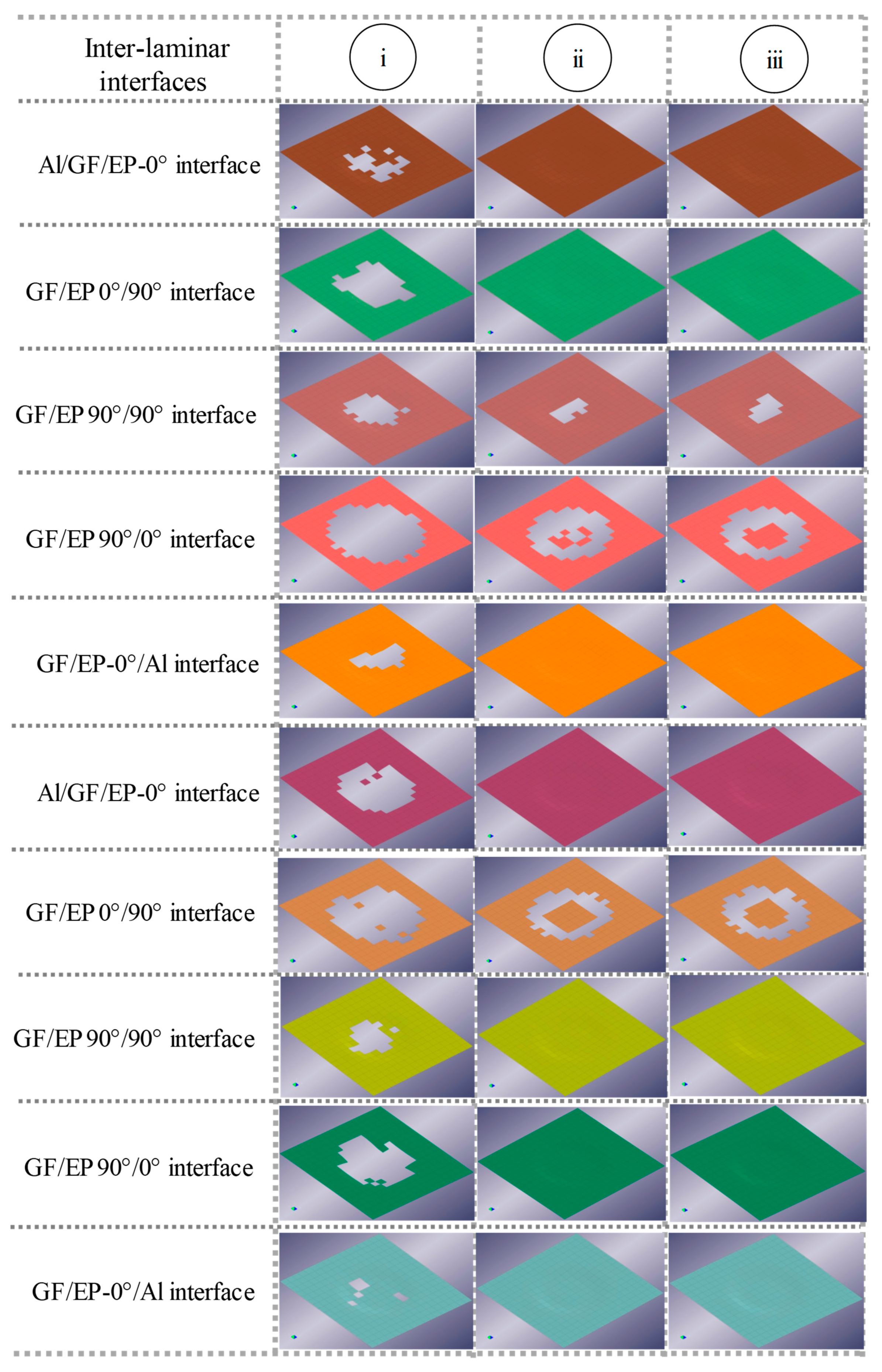
3.2. Delamination of Cohesive Interfaces

Figure 8, Figure 9 and Figure 10 show the temporal evolution of failure in each GLARE inter-laminar interface. Different colors distinguish the inter-ply failure of distinct interfaces. The interface failure was simulated in the cohesive elements by joining nodes of upper and lower volume elements of mating material layers. The time instance of interface failure was akin to the time step chosen to capture the elastoplastic deformation of GLARE, as aforementioned in Figure 5 and Figure 7. At the end of each time step, all interface failure areas were demarcated to create a ‘numerical C-scan’. The interface failure was displayed over an area of 255 × 255 mm, which circumscribed the impact zone.
The interface failure started, when the numerical scheme eroded the cohesive elements as soon as linear softening exhausted the energy of CZEs. In the incremental time steps, kinetic energy of the projectile transformed in the internal energy of GLARE laminate, making more energy available to reinforce the interface failure in the lateral direction. Noticeably, the interface failure area surfaced in dissimilar shapes, if the material and interface properties were temperature-dependent and the fiber orientation of mating GF/EP plies was dissimilar. The difference in transverse stiffness of Al-layers and GF/EP-plies promoted the mismatch of interface failure enclosures.
More interfaces delaminated with the elastoplastic deformation of GLARE (see Figure 8, Figure 9 and Figure 10), as the imbalance between compression at the impacted side and tension at the non-impacted side augmented the inter-laminar shear stresses. Yet at 80 °C, the analysis predicted significant delamination only of the GF/EP 0°/90° interfaces (see the interface failure until 0.14 ms). The GF/EP 90°/0° cohesive interface, at quarter normalized GLARE-thickness downstream from the impacted side, incurred maximum failure at room temperature and 80 °C (Figure 8, Figure 9 and Figure 10). This outcome collapsed on the same line of theoretical approximation, which identified the most delaminated interfaces also at the quarter normalized thickness of a carbon fiber-reinforced composite [70]. Though, cross-ply GF/EP laminates were incorporated in the stacking sequence, the insertion of isotropic Al-layers resulted in a quasi-isotropic behavior of the GLARE laminate. The delamination shape of each inter-ply interface, therefore, was not necessarily oriented in the fiber direction of the lower ply, which is frequently seen in monolithic composite laminates [45].

4. Experimental Procedures

4.1. Manufacturing of GLARE Specimens

The numerical predictions were assessed by conducting low velocity impact experiments on square GLARE 5A-3/2-0.3 specimens of dimension 110 mm (length) × 110 mm (width) × 1.9 mm (thickness). The areal density of the GLARE specimen was 5.6 mg/mm2 ± 1%. The GLARE panels were manufactured from Al 2024-T3 alloy sheets and S2-glass/FM94-epoxy pre-pregs. The material layers were stacked manually (see Figure 11) and cured in an autoclave at 120 °C temperature and 6 bar pressure for 90 minutes. Square specimens with dimensions of circa 110 × 110 mm were cut using a diamond saw afterwards. Ultrasonic C-scan of the specimens a priori of impact experiments elucidated no manufacturing-induced flaws or cutting-induced interface failure (delaminations or debonding) at the specimen edges.

4.2. Impact Test Method

Due to the absence of a bird strike test set-up, the experiments were conducted in a drop-weight impact tower fitted with an automated data acquisition system. This data system registered the impact force from a piezoelectric force sensor placed inside the projectile. An infrared timing gate (see Figure 12d) triggered the data acquisition system and, meanwhile, tracked the travel distance of the projectile to measure the projectile velocity.

4.3. Test Set-Up

Penetrating and non-penetrating impacts were performed by clamping the specimens between two rigid plates. The plates had a 100 × 100 mm square aperture. The clamp covered circa 3 mm wide areas of the specimen edges and provided a fixed boundary condition at four ends of the specimen (see Figure 12c). Two clamp reinforcements prevented the dynamic motion of the fixture on the test-bed and exerted more contact pressure to decrease slippage at the periphery of specimen (see Figure 12c). A blunt nose conical-shaped steel projectile impacted the GLARE specimen at the center. A re-bounce brake prevented multiple impacts on the specimen. The projectile had an approximate dimension of 4 cm (height) × 2.54 cm (diameter) and weighed 0.09 kg. The dead weight attached to the projectile resulted in a total projectile mass of 1.09 kg albeit.
To perform the impact tests at 80 °C, first the specimens were conditioned in an air-circulated environmental chamber (see Figure 12a). The specimens were placed inside the chamber after the temperature and the relative humidity in the chamber reached circa 94.5 °C and 70% RH, respectively. The conditioning time was 45 minutes in line with the early experience that concluded: a longer exposure time is imperative to homogenize the temperature through the thickness of the GLARE specimen. A circa 10 °C higher conditioning temperature was preferred to reach the planned specimen temperature in the test rig. To make sure the specimen temperature was near 80 °C, the specimens were quickly transferred from the chamber to the test rig. Despite these circumspections, thermal energy of the GLARE specimen partially dissipated in the thermal conductive steel fixture. A visual infrared thermometer showed that the specimen cooled to around 75 °C (see Figure 12b) over the brief time of transferring and clamping.

4.4. Test Matrix

Table 5 demonstrates the test conditions applied to demarcate the severity of damage of GLARE at room temperature and circa 75 °C. Keeping the projectile mass, the drop height (DH) was changed to furnish an impact velocity within 4.7–8.08 m/s. Ascribed to the limited number of specimens, two specimens were tested in each test condition.

4.5. Non-Destructive Inspection

A customized water-jet ultrasonic C-scan system checked the impacted specimens. The C-scan system comprised a flat-faced transducer and a receiver with a nozzle diameter of 8 mm and frequency of 10 MHz. The C-scan images elucidated the in-plane damage areas, however, disclosed nothing about the depth of impact damage or the delamination distribution through the GLARE thickness. This pitfall of the C-scan system is the scattered reflection of sound waves at the interfaces of differentially dense GLARE constituents.

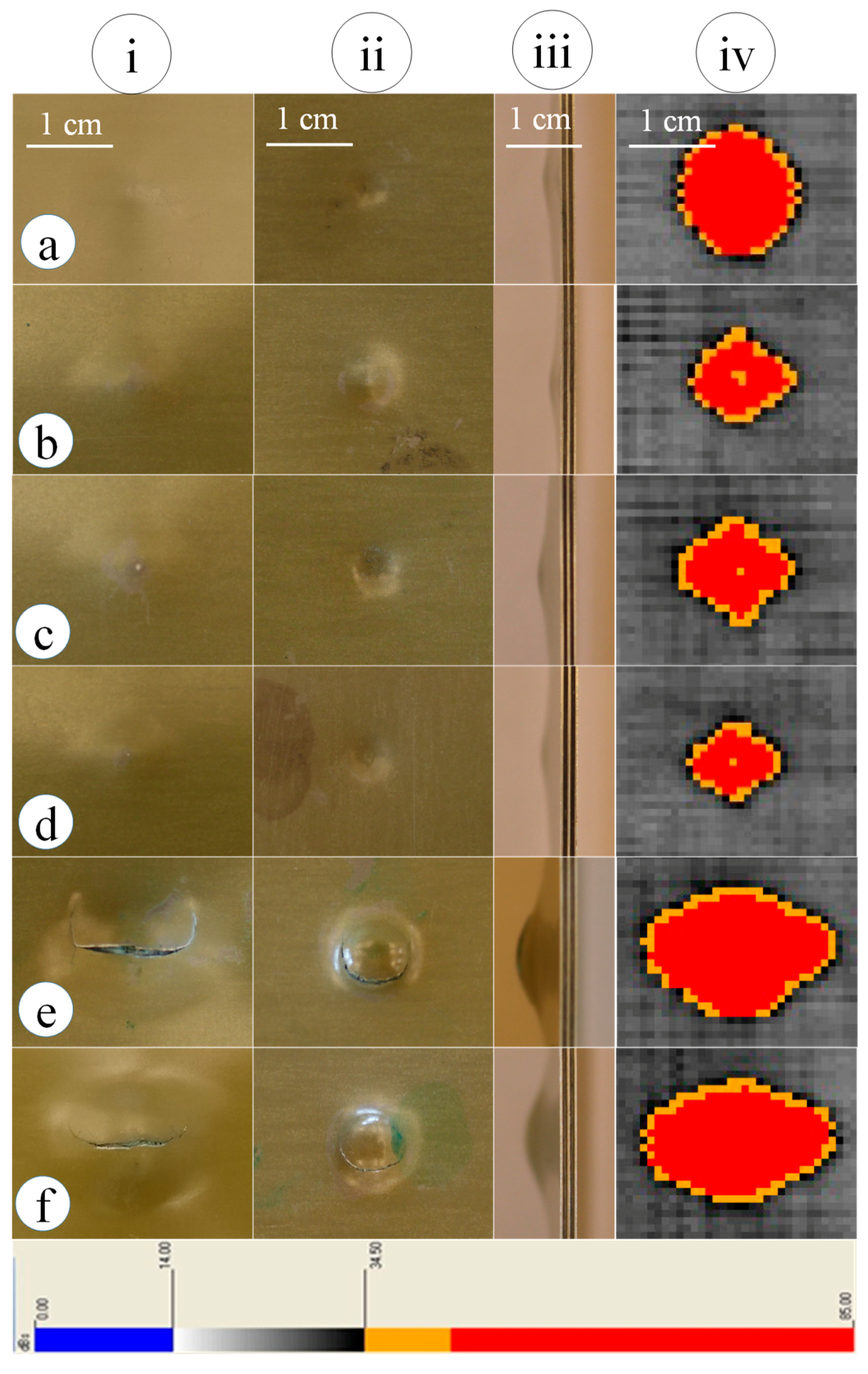
4.6. Experimental Outcomes

Figure 13 exemplifies the scanned damage area of impacted GLARE specimens. As seen in the ultrasonic C-scan images, the blunt-nose projectile inscribed in most of the impact events a pyramid shape damage in the GLARE specimens both at room temperature and 75 °C for impact energies 12 and 20 J. This impact energies corresponded to 2 m and 3 m DH, respectively. For these non-penetration impact events, the projectile kinetic energy dissipated in part in the material damage. The elastic deformation of GLARE conserved rest of the projectile kinetic energy and later, released the stored energy in the bounce-back of projectile. GLARE specimen impacted at room temperature (Figure 13a) accumulated a 76.89 mm2 larger damage area (see Table 6) than that inscribed in the GLARE plate at 75 °C (Figure 13b) for an impact energy of 12 J. Similar were the outcomes for the 20 J impacts, in which the damage area of GLARE at room temperature was 55.78 mm2 larger than that at 77.4 °C (compare Figure 13c to Figure 13d). The difference in the damage area was anticipated due to the plasticizing of epoxy at circa 75 °C that restrained the later damage growth. It is worth noting that, in 20 J impacts, the damage area was relatively smaller compared to that in the 12 J impacts for a comparable test temperature, ascribed to the local concentration of the impact energy at the expense of higher strain rate of material. The augmented material strain rate resulted in shear failure of matrix in the deep dent. By contrast, the 12 J impact energy dissipated via flexural deformation of GLARE and punched a shallow dent in a larger so-called plasticity-induced damage area. In the non-penetration impact events, the damage area enveloped the debonding of rear Al-skin at the non-impacted side.
When the impact energy sufficed to penetrate the GLARE laminate (as seen for 35.5 J impact energy related to the 4 m DH), the circular cusp of the rear Al-skin cracked parallel to the rolling direction (see Figure 13e), whereas crack in the front Al-skin (at the impacted side) followed the periphery of the indentation zone. Besides, 35.5 J impacts caused fiber breakage and fiber pull out, bending, stretching and thinning of the front and the rear Al-skins. The penetrated rear Al-skin exhibited no debonding. The material damage was visible from outside. The effect of temperature on GLARE damage area nearly disappeared in the penetration events, however (compare Figure 13e to Figure 13f and see Table 6). Of notes, the measured impact force was higher at the elevated test temperature if contrasted to that at room temperature. The relation of impact force to the test temperature persisted for all the inspected impact energies. That meant that the GLARE plate offered a higher impact resistance at the elevated test temperature, which attenuated the damage efficiency of the projectile to a large extent.

5. Discussion

High temperature conditioning released the curing-induced residual stress in GF/EP. The attenuation of residual stress suggested softening and re-solidification of fiber-epoxy interfaces and further cross-linking of the epoxy resin, which reinforced the bending stiffness of GLARE to an extent. Due to the increased bending stiffness, the GLARE specimens endured a lower bending deformation and exerted a higher resistant force for a comparable impact energy at 75 °C test temperature. Moreover, the S2-glass fibers were 83 GPa stiffer than the epoxy resin. The out-of-plane deformation disintegrated the fiber/resin interfaces through shear-induced stresses in the indentation zone, as a result. The projectile stretched the detached fibers to break them under tension, thus, less energy was allocated to the interface failure. As a result, the damage area of GLARE surfaced smaller at elevated test temperatures.
High temperature, besides, mobilized the segments of epoxy molecular chain and improved the resin ductility. The enhanced ductility of resin allowed resin plasticization, which implied that the GLARE inter-laminar interfaces behaved tougher. The resin plasticization delayed the interface failure accumulation. Perhaps the progression of interface failure was stable by comparison to an abrupt interface failure of unconditioned GLARE specimens at room temperature [11,17].
Since debonding and delamination of GLARE started earlier at room temperature, the sub-laminates took advantage of membrane stretching. The mismatch in bending stiffness of sub-laminates promoted the mode-I interface loading, inducing a large interface failure. By comparison, the pre-conditioned GLARE specimens, when subjected to a comparable impact energy at 75 °C, were at first intact at the impact center. Because, the mixed modes governed the interface failure and demanded more energy to disintegrate the interfaces.
It is to mention that the intra-laminar transverse matrix cracks can leverage the onset of inter-laminar interface failure. Besides, while cracks are present in the Al layers of GLARE, the glass fibers act as a secondary load path over the crack. This fiber bridging mechanism introduces shear stresses at the Al-GF/EP interfaces, which promote the interface debonding. Excluding the composite damage mechanism did make the model computationally less expensive. The proposed model, however, could have underestimated the extent of debonding/delamination, since the contribution of material damage in the interface failure had not been accounted for.
Another disparity to identify is the gelatin projectile of the numerical analysis compared to the solid rigid steel projectile of the experiment. The numerical impact event, with a gelatin projectile, allowed the dissipation of the projectile kinetic energy to a large extent in the projectile fragmentation. In such a soft-body impact event, the material damage—e.g., fiber failure of GF/EP—would have been negligible. By contrast, the steel projectile of the experiment did not undergo any deformation and transferred the impact energy in large to the material damage. A one-to-one comparison of a soft-body impact to a hard body one would not be ideal, therefore. Yet, the effect of service temperature and fiber orientation on the GLARE interface integrity should be comparable, since these two particulars are independent of projectile type and related strain rate of materials.
Looking at the outcomes, it can be concluded that the numerical predictions conformed to the experimental outcomes, at least in terms of the severity of material damage at different test temperatures. Of notes, this study addressed only the cross-ply GLARE 5A-3/2-0.3 configuration because of its superior impact resistance [63]. A companion study on other GLARE grades of quasi-isotropic or angular fiber orientation will ascertain the extent to which the findings of this study can be extrapolated. Besides, the metal volume fraction (MVF) of GLARE influences the ILSS and the energy dissipation. As found, the permanent dissipated impact energy decreases for increasing the MVF [72], while a single Al sheet bonded with adhesive offers the best ILSS [73]. It would be wise, therefore, to evaluate the combined influence of MVF and operating temperature on the impact resistance of GLARE.

6. Concluding Remarks

This study highlighted the coupled influence of temperature, fiber orientation, and high strain rate on the interface integrity and plastic deformation of GLARE 5A-3/2-0.3. The strain rate corresponded to low velocity impacts. The investigation on the impact response of heated GLARE outlined some interesting findings, summarized as:
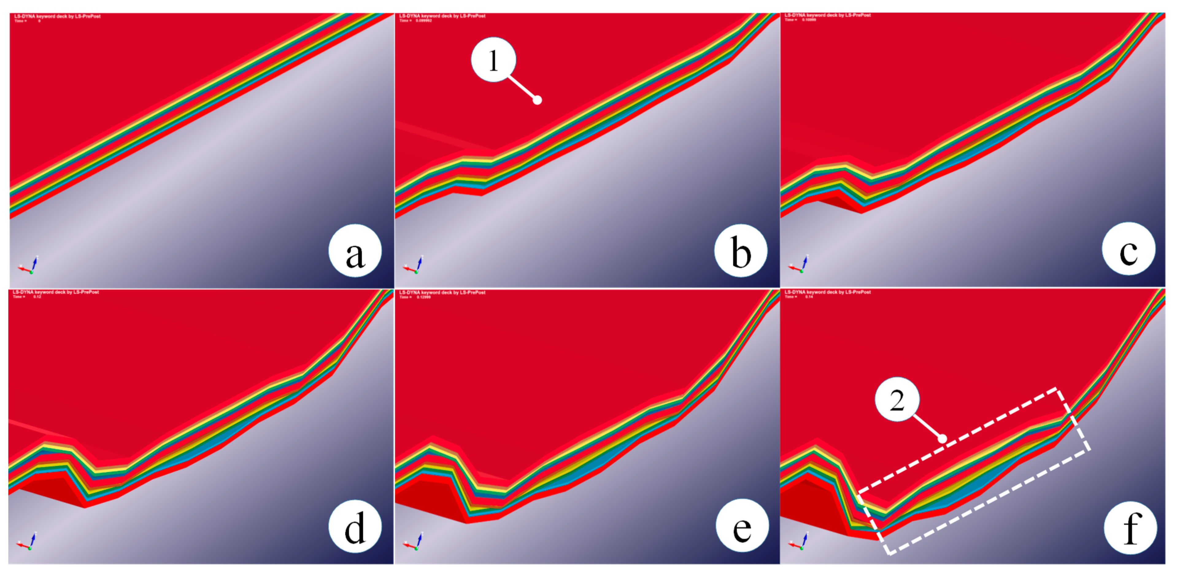
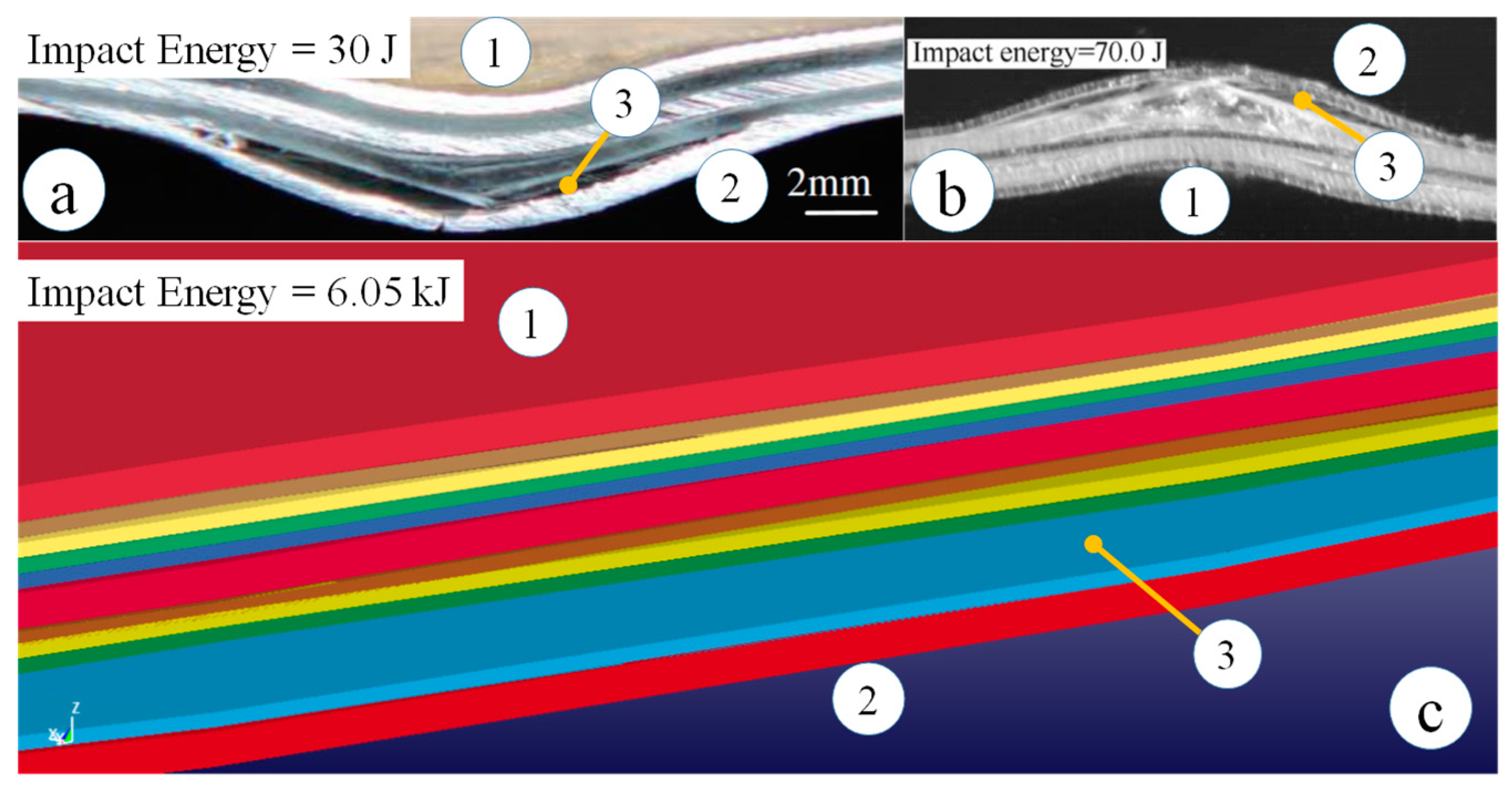
  • In the non-penetration impact events at room temperature, first the GF/EP 90°/0° cohesive interface farthest from the impacted side of the GLARE model disintegrated. Because stress waves reverberated at the rear face, which augmented the cross-ply induced shear stress beyond the limit threshold upon impact. At room temperature, the brittle behavior of cohesive elements accelerated the inter-laminar interface degradation.
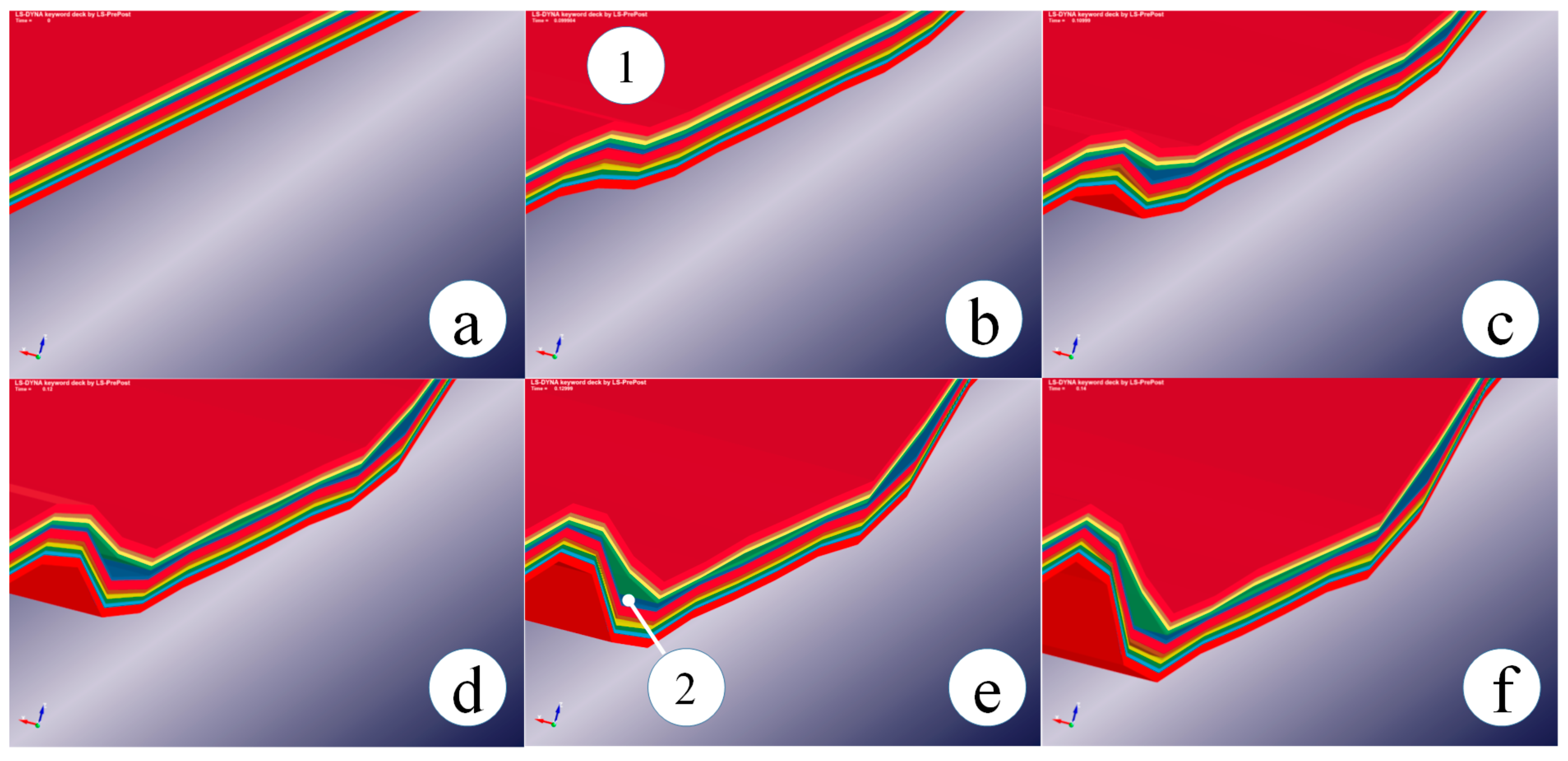
  • At 80 °C, the GLARE model endured interface failure at the periphery of impact zone, though the panel remained coherent at the impact center. In analogy to the interface degradation at room temperature, the GF/EP 0°/90° interfaces suffered severe failures at 80 °C. Nonetheless, the delamination growth was delayed at 80 °C.
  • As explicated in the experiments, FM94-epoxy behaved ductile at 75 °C. As a result, the critical strain energy release rate of FM94-epoxy was higher compared to that at room temperature. It is believed that the higher energy release rate to cohesive failure changed the stick-slip nature of interface degradation to a stable one at 75 °C. The numerical analysis, when implemented a 39% higher Gc of cohesive interfaces by contrast to that at room temperature, corroborated the stable failure of the inter-laminar interface.
  • Thermal conditioning at circa 85 °C for 45 minutes reinforced the bending stiffness of GLARE. As a result, the GLARE plate deflected only locally and offered a higher impact resistance, which restricted the impact damage with the support of resin plasticization.
  • For the sake of brevity, stress-based intra-ply fiber failure and matrix failure criteria were not included in the composite material model, although intra-ply matrix cracks can be the embryos of inter-laminar interface failure [74]. Scopes are there to complement the proposed model. However, if composite plies fail and are eroded prior to the failure of cohesive elements, convergence difficulties are inevitable.
  • This study illustrates that a lower scale of interface failure at an elevated temperature may ascertain the residual strength of GLARE at the acceptable level. Therefore, the risk of a total collapse of a thin-walled GLARE airfoil at an anti/de-icing temperature under a soft body impact is not unexpectedly high.
  • The literature review gives hundreds if not thousands of scientific articles interrogated the impact resistance and the related interface failure of GLARE and other fiber-metal laminates. Most of the studies accommodated experiments at room temperature. Thus, the question arises of whether the delineated energy partition between the different damage modes of GLARE holds also for higher operating temperatures. This study clearly shows the necessity to re-evaluate the impact performance of different GLARE grades based on the operating temperature, than just focusing on the cross-ply GLARE variant.
  • The outcomes of this study allocate new fields of application for GLARE, e.g., the energy storage of aircraft or shielding against moderate temperature. The thermal energy stored in GLARE could be converted in electric power to execute the secondary operations of an aircraft. In such cases, the landing impact should not impair the interface integrity of GLARE, if the findings of this study are extrapolated in a conservative manner.

Funding

This research received no external funding.

Conflicts of Interest

The author declares no conflict of interest.

References

  1. Kim, H.; Kedward, K.T. Modeling Hail Ice Impacts and Predicting Impact Damage Initiation in Composite Structures. AIAA J. 2000, 38, 1278–1288. [Google Scholar] [CrossRef]
  2. McCarthy, M.A.; Xiao, J.R.; McCarthy, C.T.; Kamoulakos, A.; Ramos, J.; Gallard, J.P.; Melito, V. Modelling of Bird Strike on an Aircraft Wing Leading Edge Made from Fibre Metal Laminates – Part 2: Modelling of Impact with SPH Bird Model. Appl. Compos. Mater. 2004, 11, 317–340. [Google Scholar] [CrossRef]
  3. Smojver, I.; Ivančević, D. Numerical simulation of bird strike damage prediction in airplane flap structure. Compos. Struct. 2010, 92, 2016–2026. [Google Scholar] [CrossRef]
  4. Takeda, S.; Minakuchi, S.; Okabe, Y.; Takeda, N. Delamination monitoring of laminated composites subjected to low-velocity impact using small-diameter FBG sensors. Compos. Part A Appl. Sci. Manuf. 2005, 36, 903–908. [Google Scholar] [CrossRef]
  5. Vlot, A.; Gunnink, J.W. Fibre Metal Laminates. An Introduction; Springer: Dordrecht, The Netherlands, 2001; ISBN 978-94-010-0995-9. [Google Scholar]
  6. Guan, Z.W.; Cantwell, W.J.; Abdullah, R. Numerical modeling of the impact response of fiber-metal laminates. Polym. Compos. 2009, 30, 603–611. [Google Scholar] [CrossRef]
  7. Wu, G.; Yang, J.-M. The mechanical behavior of GLARE laminates for aircraft structures. JOM 2005, 57, 72–79. [Google Scholar] [CrossRef]
  8. Morency, F.; Tezok, F.; Paraschivoiu, I. Heat and Mass Transfer in the Case of Anti-Icing System Simulation. J. Aircr. 2000, 37, 245–252. [Google Scholar] [CrossRef]
  9. Morency, F.; Tezok, F.; Paraschivoiu, I. Anti-Icing System Simulation Using CANICE. J. Aircr. 1999, 36, 999–1006. [Google Scholar] [CrossRef]
  10. Hagenbeek, M. Characterisation of Fiber metal laminates under Thermo-mechanical Loadings. Available online: https://www.elibrary.ru/item.asp?id=9358929 (accessed on 9 March 2020).
  11. Zhong, Y.; Joshi, S.C. Impact behavior and damage characteristics of hygrothermally conditioned carbon epoxy composite laminates. Mater. Design (1980–2015) 2015, 65, 254–264. [Google Scholar] [CrossRef]
  12. Zimmerman, R.S.; Adams, R.D. (Eds.) Impact Performance of Various Fiber Reinforced Composites as a Function of Temperature; Int SAMPE Symp Exhib.: Anaheim, CA, USA, 1987. [Google Scholar]
  13. Levin, K. (Ed.) Effect of Low-Velocity Impact on Compression Strength of Quasi-Isotropic Laminate; 1st Technical Conference, Dayton, Ohio.; Technomic Publishing Co.: Lanchester, NH, USA, 1986. [Google Scholar]
  14. Botelho, E.C.; Almeida, R.S.; Pardini, L.C.; Rezende, M.C. Elastic properties of hygrothermally conditioned glare laminate. Int. J. Eng. Sci. 2007, 45, 163–172. [Google Scholar] [CrossRef]
  15. Botelho, E.C.; Pardini, L.C.; Rezende, M.C. Hygrothermal effects on the shear properties of carbon fiber/epoxy composites. J. Mater. Sci. 2006, 41, 7111–7118. [Google Scholar] [CrossRef]
  16. Liotier, P.-J.; Vautrin, A.; Beraud, J.-M. Microcracking of composites reinforced by stitched multiaxials subjected to cyclical hygrothermal loadings. Compos. Part A Appl. Sci. Manuf. 2011, 42, 425–437. [Google Scholar] [CrossRef]
  17. Zhong, Y.; Joshi, S.C. Impact resistance of hygrothermally conditioned composite laminates with different lay-ups. J. Compos. Mater. 2015, 49, 829–841. [Google Scholar] [CrossRef]
  18. Khashaba, U.A.; Othman, R. Low-velocity impact of woven CFRE composites under different temperature levels. Int. J. Impact Eng. 2017, 108, 191–204. [Google Scholar] [CrossRef]
  19. Hirai, Y.; Hamada, H.; Kim, J.-K. Impact response of woven glass-fabric composites—II. Effect of temperature. Compos. Sci. Technol. 1998, 58, 119–128. [Google Scholar] [CrossRef]
  20. Johnson, W. (Ed.) Delamination and Debonding of Materials; ASTM International: West Conshohocken, PA, USA, 19428-2959; 1985; ISBN 978-0-8031-0414-3. [Google Scholar]
  21. Johnson, W.S.; Masters, J.E.; Karasek, M.L.; Strait, L.H.; Amateau, M.F.; Runt, J.P. Effect of Temperature and Moisture on the Impact Behavior of Graphite/Epoxy Composites: Part II—Impact Damage. J. Compos. Technol. Res. 1995, 17, 11. [Google Scholar] [CrossRef]
  22. Johnson, W.S.; Masters, J.E.; Karasek, M.L.; Strait, L.H.; Amateau, M.F.; Runt, J.P. Effect of Temperature and Moisture on the Impact Behavior of Graphite/Epoxy Composites: Part I—Impact Energy Absorption. J. Compos. Technol. Res. 1995, 17, 3. [Google Scholar] [CrossRef]
  23. Li, G.; Pang, S.-S.; Helms, J.E.; Ibekwe, S.I. Low velocity impact response of GFRP laminates subjected to cycling moistures. Polym. Compos. 2000, 21, 686–695. [Google Scholar] [CrossRef]
  24. Wyatt, R.C.; Ashbee, K.H.G. Debonding in carbon fibre/polyester resin composites exposed to water: Comparison with ‘E’ glass fibre composites. Fibre Science and Technology 1969, 2, 29–40. [Google Scholar] [CrossRef]
  25. Antoon, M.K.; Koenig, J.L.; Serafini, T. Fourier-transform infrared study of the reversible interaction of water and a crosslinked epoxy matrix. J. Polym. Sci. Polym. Phys. Ed. 1981, 19, 1567–1575. [Google Scholar] [CrossRef]
  26. Chamis, C.C. (Ed.) Test Methods and Design Allowables for Fibrous Composites; ASTM International: West Conshohocken, PA, USA, 19428-2959; 1981; ISBN 978-0-8031-0700-7. [Google Scholar]
  27. Porter, T.R. Environmental Effects on Composite Fracture Behavior. In Test Methods and Design Allowables for Fibrous Composites; Chamis, C.C., Ed.; ASTM International: West Conshohocken, PA, USA, 19428-2959; 1981; 396-396-15; ISBN 978-0-8031-0700-7. [Google Scholar]
  28. Shen, C.-H.; Springer, G.S. Effects of Moisture and Temperature on the Tensile Strength of Composite Materials. J. Compos. Mater. 1977, 11, 2–16. [Google Scholar] [CrossRef]
  29. Sun, P.; Zhao, Y.; Luo, Y.; Sun, L. Effect of temperature and cyclic hygrothermal aging on the interlaminar shear strength of carbon fiber/bismaleimide (BMI) composite. Mater. Design (1980-2015) 2011, 32, 4341–4347. [Google Scholar] [CrossRef]
  30. Ray, B.C. Temperature effect during humid ageing on interfaces of glass and carbon fibers reinforced epoxy composites. J. Colloid Interface Sci. 2006, 298, 111–117. [Google Scholar] [CrossRef] [PubMed]
  31. Asp, L.E. The effects of moisture and temperature on the interlaminar delamination toughness of a carbon/epoxy composite. Compos. Sci. Technol. 1998, 58, 967–977. [Google Scholar] [CrossRef]
  32. Coronado, P.; Argüelles, A.; Viña, J.; Mollón, V.; Viña, I. Influence of temperature on a carbon–fibre epoxy composite subjected to static and fatigue loading under mode-I delamination. Int. J. Solids Struct. 2012, 49, 2934–2940. [Google Scholar] [CrossRef] [Green Version]
  33. Banea, M.D.; Silva, L.F.M.d.; Campilho, R.D.S.G. Effect of Temperature on Tensile Strength and Mode I Fracture Toughness of a High Temperature Epoxy Adhesive. J. Adhes. Sci. Technol. 2012, 26, 939–953. [Google Scholar] [CrossRef]
  34. Charalambous, G.; Allegri, G.; Hallett, S.R. Temperature effects on mixed mode I/II delamination under quasi-static and fatigue loading of a carbon/epoxy composite. Compos. Part A Appl. Sci. Manuf. 2015, 77, 75–86. [Google Scholar] [CrossRef] [Green Version]
  35. Russell, A.J.; Street, K.N. Moisture and Temperature Effects on the Mixed-Mode Delamination Fracture of Unidirectional Graphite/Epoxy. In Delamination and Debonding of Materials; Johnson, W.S., Ed.; ASTM International: West Conshohocken, PA, USA, 19428-2959; 1985; 349-349-22; ISBN 978-0-8031-0414-3. [Google Scholar]
  36. Ashcroft, I.A.; Hughes, D.J.; Shaw, S.J. Mode I fracture of epoxy bonded composite joints: 1. Quasi-static loading. Int. J. Adhes. Adhes. 2001, 21, 87–99. [Google Scholar] [CrossRef]
  37. Aliyu, A.A.; Daniel, I.M. Effects of Strain Rate on Delamination Fracture Toughness of Graphite/Epoxy. In Delamination and Debonding of Materials; Johnson, W.S., Ed.; ASTM International: West Conshohocken, PA, USA, 19428-2959; 1985; 336-336-13; ISBN 978-0-8031-0414-3. [Google Scholar]
  38. Kim, B.W.; Mayer, A.H. Influence of fiber direction and mixed-mode ratio on delamination fracture toughness of carbon/epoxy laminates. Compos. Sci. Technol. 2003, 63, 695–713. [Google Scholar] [CrossRef]
  39. Benzeggagh, M.L.; Kenane, M. Measurement of mixed-mode delamination fracture toughness of unidirectional glass/epoxy composites with mixed-mode bending apparatus. Compos. Sci. Technol. 1996, 56, 439–449. [Google Scholar] [CrossRef]
  40. Hashemi, S.; Kinloch, A.J.; Williams, G. Mixed-Mode Fracture in Fiber-Polymer Composite Laminates. In Composite Materials: Fatigue and Fracture (Third Volume); O’Brien, T.K., Ed.; ASTM International: West Conshohocken, PA, USA, 19428-2959; 1991; 143-143-26; ISBN 978-0-8031-1419-7. [Google Scholar]
  41. O’Brien, T.K. (Ed.) Composite Materials: Fatigue and Fracture (Third Volume); ASTM International: West Conshohocken, PA, USA, 19428-2959; 1991; ISBN 978-0-8031-1419-7. [Google Scholar]
  42. Feng, W.W.; Reifsnider, K.L.; Sendeckyj, G.P.; Chiao, T.T.; Rodericks, G.L.; Stinchcomb, W.W.; de Vore, L.; Hunston, D.L.; Bascom, W.D. Effects of Lay-Up, Temperature, and Loading Rate in Double Cantilever Beam Tests of Interlaminar Crack Growth. J. Compos. Technol. Res. 1983, 5, 118. [Google Scholar] [CrossRef]
  43. Fan, J.; Guan, Z.W.; Cantwell, W.J. Numerical modelling of perforation failure in fibre metal laminates subjected to low velocity impact loading. Compos. Struct. 2011, 93, 2430–2436. [Google Scholar] [CrossRef]
  44. Laliberté, J.; Straznicky, P.V.; Poon, C. Impact Damage in Fiber Metal Laminates, Part 1: Experiment. AIAA J. 2005, 43, 2445–2453. [Google Scholar] [CrossRef]
  45. Lu, X.; Ridha, M.; Chen, B.Y.; Tan, V.B.C.; Tay, T.E. On cohesive element parameters and delamination modelling. Eng. Fract. Mech. 2019, 206, 278–296. [Google Scholar] [CrossRef]
  46. Guida, M.; Marulo, F.; Meo, M.; Russo, S. Experimental Tests Analysis of Fiber Metal Laminate under Birdstrike. Mech. Adv. Mater. Struct. 2012, 19, 376–395. [Google Scholar] [CrossRef] [Green Version]
  47. Guida, M. Study Design and Testing of Structural Configurations for the Bird-Strike Compliance of Aeronautical Components; CUEN: Roma, Italy, 2008; ISBN 978-8871467658. [Google Scholar]
  48. Hedayati, R.; Ziaei-Rad, S. A new bird model and the effect of bird geometry in impacts from various orientations. Aerosp. Sci. Technol. 2013, 28, 9–20. [Google Scholar] [CrossRef]
  49. Morinière, F.D.; Alderliesten, R.C.; Sadighi, M.; Benedictus, R. An integrated study on the low-velocity impact response of the GLARE fibre-metal laminate. Compos. Struct. 2013, 100, 89–103. [Google Scholar] [CrossRef]
  50. Seidt, J.D.; Gilat, A. Plastic deformation of 2024-T351 aluminum plate over a wide range of loading conditions. Int. J. Solids Struct. 2013, 50, 1781–1790. [Google Scholar] [CrossRef]
  51. Dogan, F.; Hadavinia, H.; Donchev, T.; Bhonge, P. Delamination of impacted composite structures by cohesive zone interface elements and tiebreak contact. Open Eng. 2012, 2, 96. [Google Scholar] [CrossRef] [Green Version]
  52. Da Silva, L.F.M.; Adams, R.D. Measurement of the mechanical properties of structural adhesives in tension and shear over a wide range of temperatures. J. Adhes. Sci. Technol. 2005, 19, 109–141. [Google Scholar] [CrossRef]
  53. Mao, R.H.; Meguid, S.A.; Ng, T.Y. Effects of incidence angle in bird strike on integrity of aero-engine fan blade. Int. J. Crashworthiness 2009, 14, 295–308. [Google Scholar] [CrossRef]
  54. Monaghan, J.J. Smoothed Particle Hydrodynamics. Annu. Rev. Astron. Astrophys. 1992, 30, 543–574. [Google Scholar] [CrossRef]
  55. Guida, M.; Marulo, F.; Meo, M.; Grimaldi, A.; Olivares, G. SPH – Lagrangian study of bird impact on leading edge wing. Compos. Struct. 2011, 93, 1060–1071. [Google Scholar] [CrossRef]
  56. Harding, M.M.; Ruiz, C. The Mechanical Behaviour of Composite Materials under Impact Loading. KEM 1997, 141–143, 403–426. [Google Scholar] [CrossRef]
  57. Vural, M.; Ravichandran, G. Transverse Failure in Thick S2-Glass/ Epoxy Fiber-Reinforced Composites. J. Compos. Mater. 2004, 38, 609–623. [Google Scholar] [CrossRef]
  58. Lässig, T.; Nguyen, L.; May, M.; Riedel, W.; Heisserer, U.; van der Werff, H.; Hiermaier, S. A non-linear orthotropic hydrocode model for ultra-high molecular weight polyethylene in impact simulations. Int. J. Impact Eng. 2015, 75, 110–122. [Google Scholar] [CrossRef]
  59. Vo, T.P.; Guan, Z.W.; Cantwell, W.J.; Schleyer, G.K. Low-impulse blast behaviour of fibre-metal laminates. Compos. Struct. 2012, 94, 954–965. [Google Scholar] [CrossRef] [Green Version]
  60. Johnson, A.F.; Holzapfel, M. Influence of delamination on impact damage in composite structures. Compos. Sci. Technol. 2006, 66, 807–815. [Google Scholar] [CrossRef]
  61. Fan, C.; Jar, P.-Y.B.; Cheng, J.R. Cohesive zone with continuum damage properties for simulation of delamination development in fibre composites and failure of adhesive joints. Eng. Fract. Mech. 2008, 75, 3866–3880. [Google Scholar] [CrossRef]
  62. Soutis, C.; Mohamed, G.; Hodzic, A. Modelling the structural response of GLARE panels to blast load. Compos. Struct. 2011, 94, 267–276. [Google Scholar] [CrossRef]
  63. Yaghoubi, A.S.; Liaw, B. Effect of lay-up orientation on ballistic impact behaviors of GLARE 5 FML beams. Int. J. Impact Eng. 2013, 54, 138–148. [Google Scholar] [CrossRef]
  64. Yaghoubi, A.S.; Liu, Y.; Liaw, B. Low-Velocity Impact on GLARE 5 Fiber-Metal Laminates: Influences of Specimen Thickness and Impactor Mass. J. Aerosp. Eng. 2012, 25, 409–420. [Google Scholar] [CrossRef]
  65. Naghipour, P.; Bartsch, M.; Voggenreiter, H. Simulation and experimental validation of mixed mode delamination in multidirectional CF/PEEK laminates under fatigue loading. Int. J. Solids Struct. 2011, 48, 1070–1081. [Google Scholar] [CrossRef]
  66. General Civil Aviation Authority. Runway Impact during Attempted Go-Around; Preliminary report, Operator; AAIS Case no. AIFN/0008/2016; Emirates: Abu Dhabi, Arab, 2016.
  67. Anderson, C.E. An overview of the theory of hydrocodes. Int. J. Impact Eng. 1987, 5, 33–59. [Google Scholar] [CrossRef]
  68. Seo, H.; Hundley, J.; Hahn, H.T.; Yang, J.-M. Numerical Simulation of Glass-Fiber-Reinforced Aluminum Laminates with Diverse Impact Damage. AIAA J. 2010, 48, 676–687. [Google Scholar] [CrossRef]
  69. Caprino, G.; Spataro, G.; Del Luongo, S. Low-velocity impact behaviour of fibreglass–aluminium laminates. Compos. Part A Appl. Sci. Manuf. 2004, 35, 605–616. [Google Scholar] [CrossRef]
  70. Kassapoglou, C. Modeling the Effect of Damage in Composite Structures. Simplified Approaches/Christos Kassapoglou, Delft University of Technology, The Netherlands; Wiley: Chichester, West Sussex, UK, 2015; ISBN 978-1-119-01321-1. [Google Scholar]
  71. Chen, Q.; Guan, Z.; Li, Z.; Ji, Z.; Zhuo, Y. Experimental investigation on impact performances of GLARE laminates. Chin. J. Aeronaut. 2015, 28, 1784–1792. [Google Scholar] [CrossRef] [Green Version]
  72. Bikakis, G.S.E.; Savaidis, A.; Zalimidis, P.; Tsitos, S. Influence of the Metal Volume Fraction on the permanent dent depth and energy absorption of GLARE plates subjected to low velocity impact. IOP Conf. Ser.: Mater. Sci. Eng. 2016, 161, 12055. [Google Scholar] [CrossRef] [Green Version]
  73. Bellini, C.; Di Cocco, V.; Iacoviello, F.; Sorrentino, L. Influence of structural characteristics on the interlaminar shear strength of CFRP/Al fibre metal laminates. Procedia Struct. Integr. 2019, 18, 373–378. [Google Scholar] [CrossRef]
  74. Zheng, S.; Sun, C.T. A double-plate finite-element model for the impact-induced delamination problem. Compos. Sci. Technol. 1995, 53, 111–118. [Google Scholar] [CrossRef]
Figure 1. GLARE 5A-3/2-0.3 laminate and its cohesive interfaces; a unique color stands for an interface; X-axis and Y-axis are aligned with the fiber direction and the transverse-fiber direction.
Aerospace 07 00028 g001
Figure 2. Cylindrical projectile consists of particles.
Aerospace 07 00028 g002
Figure 3. Plastic response of Al 2024-T3 at different temperatures and strain rates [50].
Aerospace 07 00028 g003
Figure 4. Bilinear traction-separation law of mixed-mode interface failure.
Aerospace 07 00028 g004
Figure 5. Sub-laminates through the GLARE thickness attributed to debonding and delamination at (a) 0 ms (initial state), (b) 0.099 ms, (c) 0.11 ms, (d) 0.12 ms, (e) 0.13 ms, (f) 0.14 ms; 1 indicates the impacted side; 2 stands for the impact zone where all the interfaces failed; material and interface properties correspond to room temperature; impact velocity 82 m/s; the fragmented projectile is not included in the imagery to facilitate the pictorial analysis.
Aerospace 07 00028 g005
Figure 6. Delamination failure of GLARE laminates determined by (a) Yaghoubi et al. [64], (b) Chen et al. [71], and (c) numerical analysis of this study; 1 and 2 stand for the impacted side and the non-impacted side, respectively; 3 stands for the GF/EP-90°/0° interface delamination at room temperature.
Aerospace 07 00028 g006
Figure 7. Sub-laminates through the GLARE thickness attributed to delamination at (a) 0 ms (initial state), (b) 0.099 ms, (c) 0.11 ms, (d) 0.12 ms, (e) 0.13 ms, (f) 0.14 ms; 1 indicates the impacted side; 2 stands for the GF/EP 90°/0° interface delamination; material and interface properties correspond to 80 °C, considering a 39% increase of Gc of cohesive interfaces; impact velocity 82 m/s; the fragmented projectile is not included in the imagery to facilitate the pictorial analysis.
Aerospace 07 00028 g007
Figure 8. Debonding and delamination of cohesive interfaces of the GLARE laminate (i) at room temperature, (ii) at 80°C (39% tougher epoxy-FM94), and (iii) at 80°C (45% tougher epoxy-FM94) at 0.099 ms; the cohesive interfaces are organized from the impacted (top) to the non-impacted (bottom) side.
Aerospace 07 00028 g008
Figure 9. Debonding and delamination of cohesive interfaces of the GLARE laminate (i) at room temperature, (ii) at 80 °C (39% tougher epoxy-FM94), and (iii) at 80 °C (45% tougher epoxy-FM94) at 0.12 ms; the cohesive interfaces are organized from the impacted (top) to the non-impacted (bottom) side.
Aerospace 07 00028 g009
Figure 10. Debonding and delamination of cohesive interfaces of the GLARE laminate (i) at room temperature, (ii) at 80 °C (39% tougher FM94-epoxy), and (iii) at 80 °C (45% tougher FM94-epoxy) at 0.14 ms; the cohesive interfaces are organized from the impacted (top) to the non-impacted (bottom) side.
Aerospace 07 00028 g010
Figure 11. (a) Hand lay-up of the GLARE stack; (b) breather fabric and air-tight plastic foil covering the GLARE panels on the stainless-steel bed of the autoclave prior to curing; red arrows indicate the location of GLARE panels on the autoclave bed.
Aerospace 07 00028 g011
Figure 12. Instruments of the impact test set-up, (a) an air-circulated environmental chamber, (1) conditioning chamber; (b) the specimen cooled to around 75 °C, (5) thermal imaging camera; (c) the clamp covered circa 3 mm wide areas of the specimen edges, (2) GLARE specimen, (3) clamp, (4) clamp reinforcement; (d) an infrared timing gate, (6) infrared timing gate; (7) projectile.
Aerospace 07 00028 g012
Figure 13. Damage area of the impacted GLARE specimens for (a) room temperature and 2 m DH, (b) 75 °C and 2 m DH, (c) room temperature and 3 m DH, (d) 77.4 °C and 3 m DH, (e) room temperature and 4 m DH, and (f) 77 °C and 4 m DH; alphabetic specimen order corresponds to the impact test condition in Table 5; rows (i), (ii), (iii), and (iv) stand for rear view, front view, side view, and c-scan image, respectively; the legend indicates the attenuation of ultrasonic waves in C-scan.
Aerospace 07 00028 g013
Table 1. Material properties of GF/EP.
Mechanical Properties of GF/EP (unidirectional ply)
Propertiesat Room Temperatureat 80 °C
Density (kg/mm3)1.98 × 10−61.98 × 10−6
Tensile modulus, E11 (GPa)5442.22
Tensile modulus, E22 (GPa)9.40.15
Tensile modulus, E33 (GPa)9.40.15
Poisson’s ratio ( υ 21)0.05740.0011
Poisson’s ratio ( υ 31)0.05740.0011
Poisson’s ratio ( υ 32)0.430.25
Shear modulus, G12 (GPa)5.50.1
Shear modulus, G13 (GPa)5.50.1
Shear modulus, G23 (GPa)3.30.06
Table 2. Material properties of Al.
Mechanical Properties of Aluminum (Al 2024-T3)
Propertiesat Room Temperatureat 80 °C
Density (kg/mm3)2.78 × 10−62.78 × 10−6
E-modulus (GPa)73.171
Shear modulus (GPa)2826
Table 3. Material properties of a cohesive interface.
Material Properties of a Cohesive Interface in a Mixed-Mode Loading Condition
PropertiesAt Room TemperatureAt 80 °C
Density (kg/mm3)1.20 × 10−61.20 × 10−6
E-modulus (GPa)3.92.12
Critical strain energy release rate GIc, (J/mm2)0.00250.00363
Critical strain energy release rate GIIc, (J/mm2)0.0090.01309
Peak traction in peel (T), (GPa)0.00820.0046
Peak traction in shear (S), (GPa)0.04660.0348
Table 4. Compressibility and volumetric strain of the gelatin projectile.
εv10−0.095−0.104−0.112−0.117−0.125−0.131−0.148−0.232
C (GPa)−500.2941.472.944.415.887.3514.773.5
Table 5. Test matrix of low velocity impact on GLARE.
Specimen No.Areal Density (mg/mm2)Drop Height (m)Temperature (°C)Impact Velocity (m/s)Actual Impact Energy (J)
(a)5.62room4.7712.4
(b)5.62754.611.53
(c)5.63room6.1820.81
(d)5.6377.45.9819.48
(e)5.64room8.0835.58
(f)5.64778.0735.49
Table 6. Experimental outcomes of low velocity impact on GLARE.
Specimen No.Temperature(°C)Impact Velocity (m/s)Damage ShapeMajor Radius (mm)Minor Radius (mm)Area (mm2)Impact Force (N)
(a)room4.77circular7.67.2171.874099
(b)754.6pyramid5.65.494.984910
(c)room6.18pyramid6.86.4136.695800
(d)77.45.98pyramid5.64.680.917246
(e)room8.08elliptical11.47.6272.136371
(f)778.07elliptical11.47.2257.816721

