1. Introduction
There is a growing recognized need for miniature flight vehicles with multifunctional capabilities, such as micro air vehicles (MAVs) for both military and civilian surveillance [
1,
2,
3,
4]. Flapping wing flight of birds provides us with a sophisticated example of utilizing unsteady aerodynamics to mechanize the miniature flight structures at low Reynolds numbers (10
3–10
5) [
5,
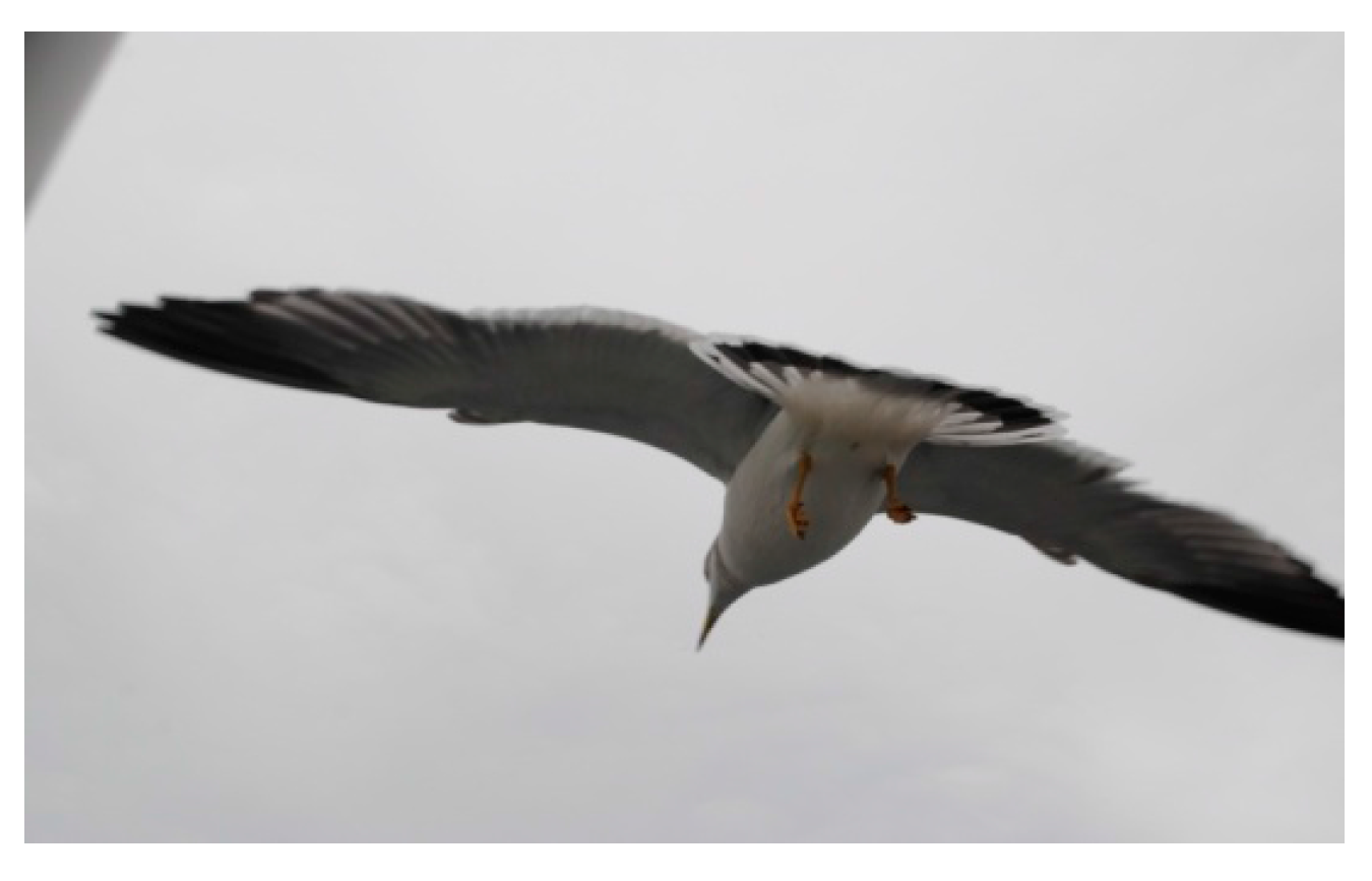
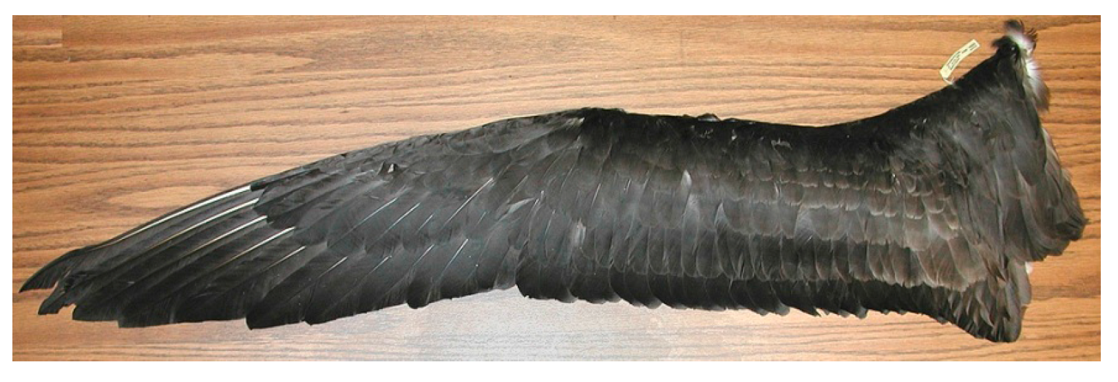
6]. We attempt to mimic both the long-distance birds, due to their natural long-endurance manner, and their high lift production during take-off (start-up). The albatross, as shown in
Figure 1 and
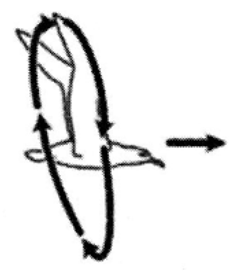
Figure 2, is chosen to represent long distance migratory birds. It is about the size of our intended flapping wing based surveillance MAV. We hope to mimic albatross’s flapping flight to achieve this long-distance characteristic. It is used for investigating flow characteristic aiming at better design of flapping MAV. The wingspan of the albatross is 60 cm. The flapping pattern of the albatross is of the avian type,
i.e., vertical motion as shown in
Figure 3. Our model simulated the complete, three-dimensional, unsteady flow fields around this type of wing with large-scale vortices.
Figure 1.
Albatross in flight.
Figure 1.
Albatross in flight.
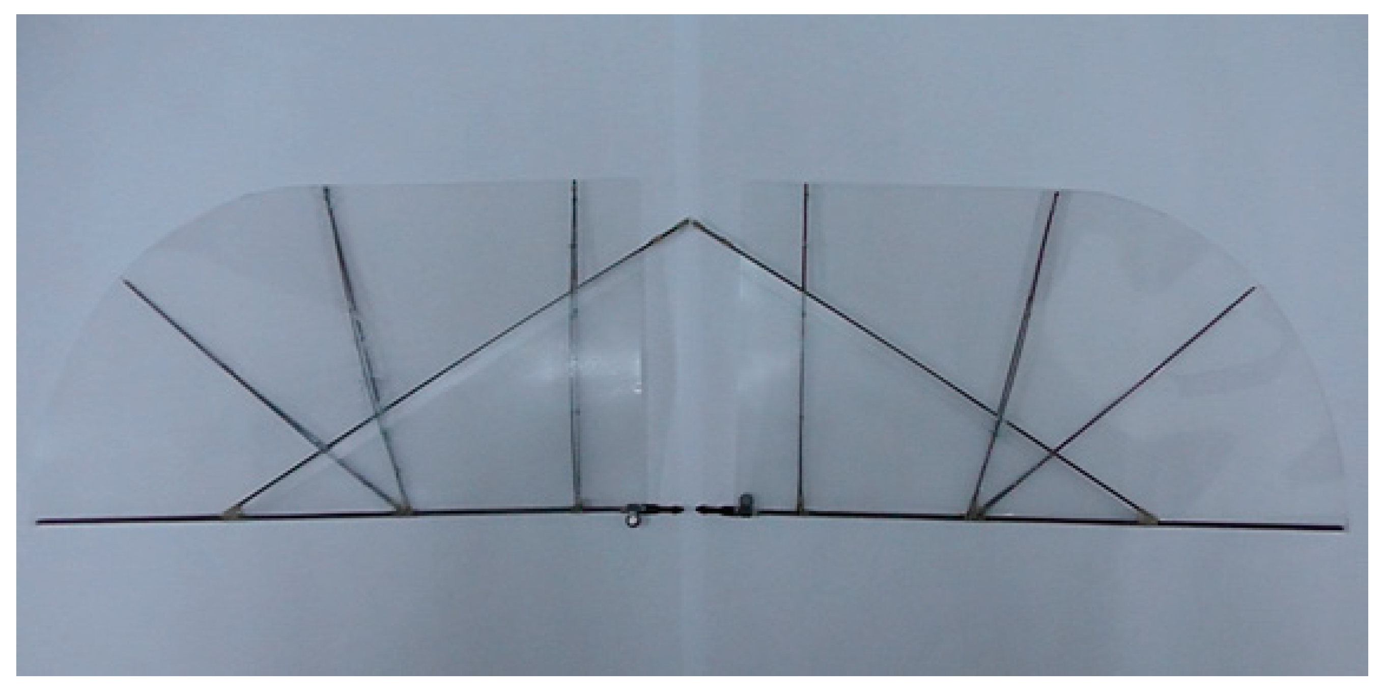
Figure 2.
Albatross wing model.
Figure 2.
Albatross wing model.
Figure 3.
The flapping pattern of albatross is avian type, i.e., more up/down vertically.
Figure 3.
The flapping pattern of albatross is avian type, i.e., more up/down vertically.
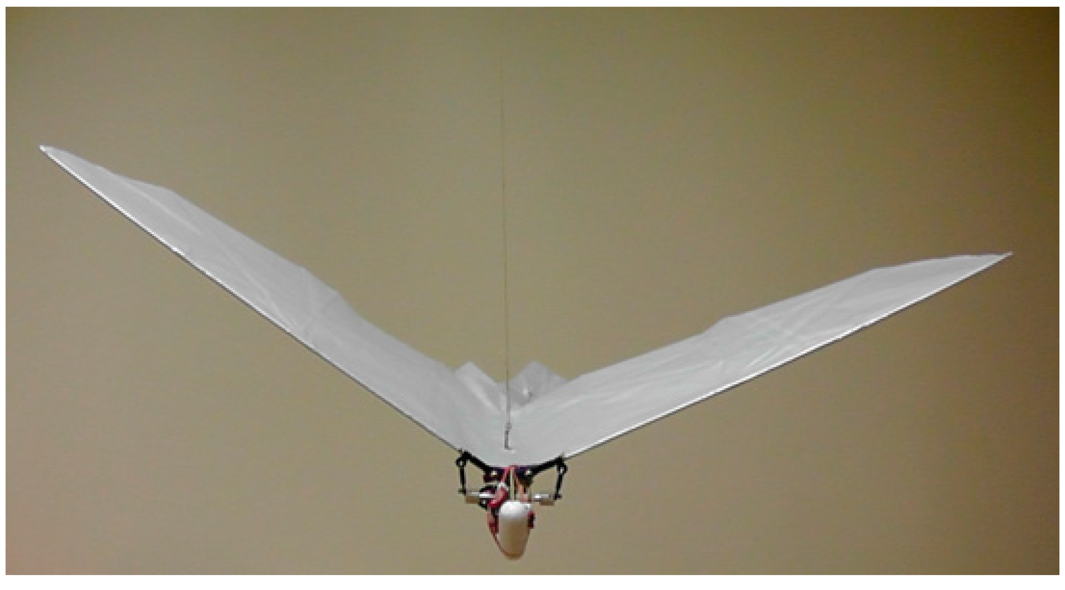
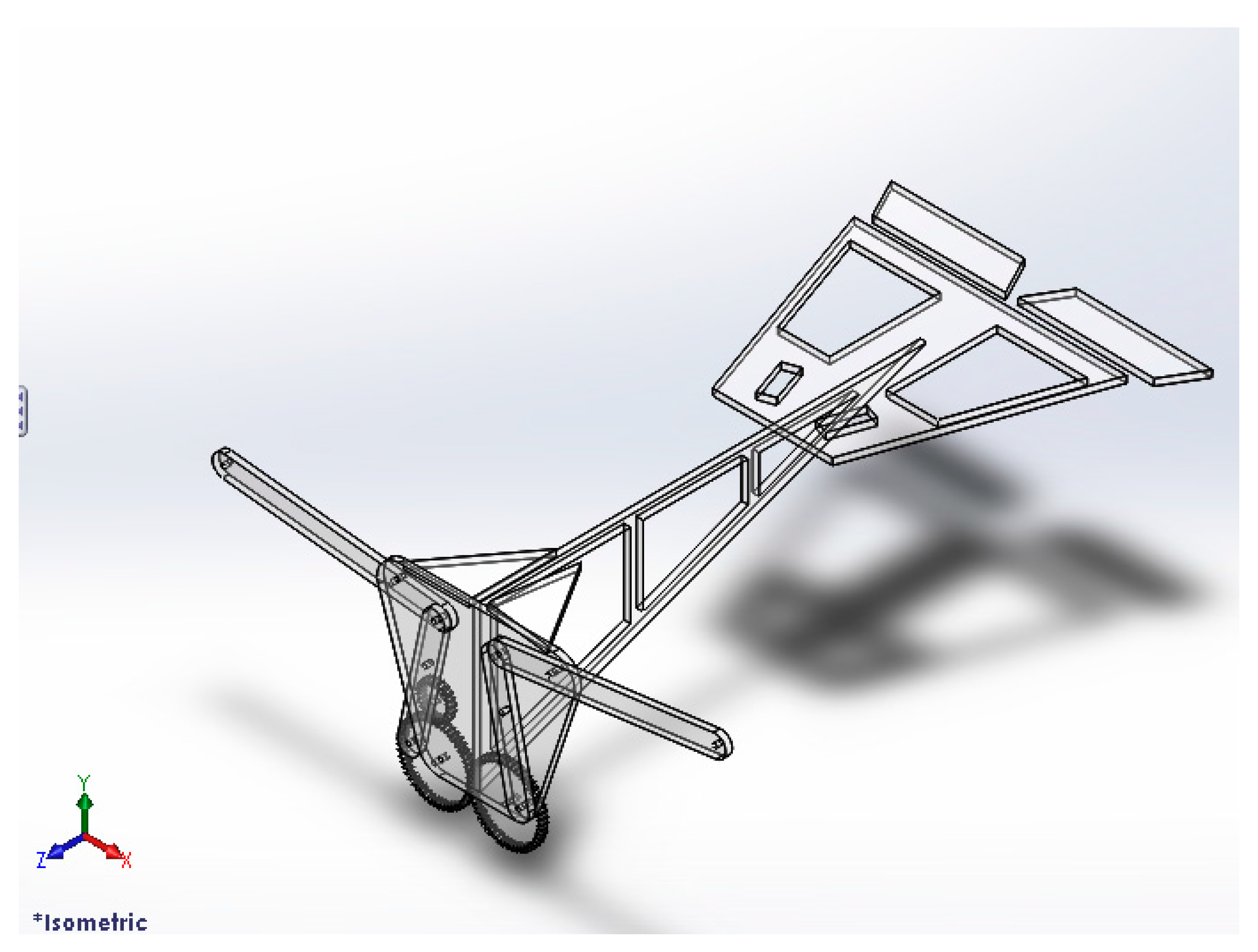
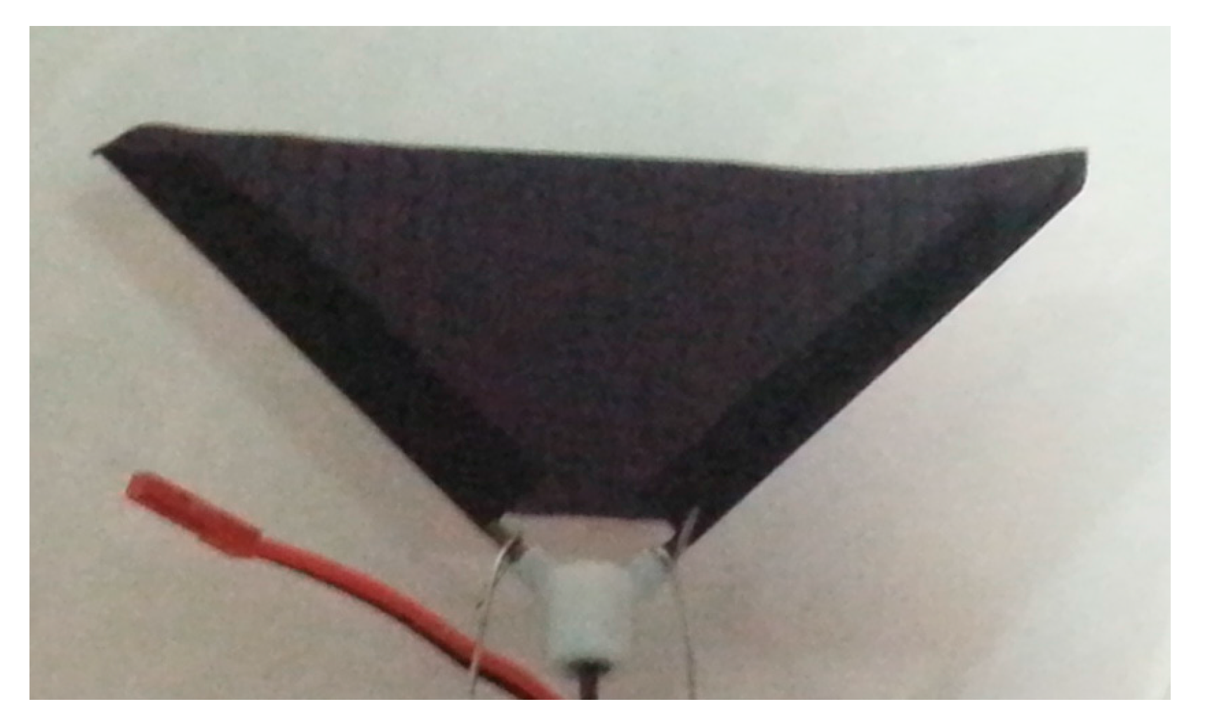
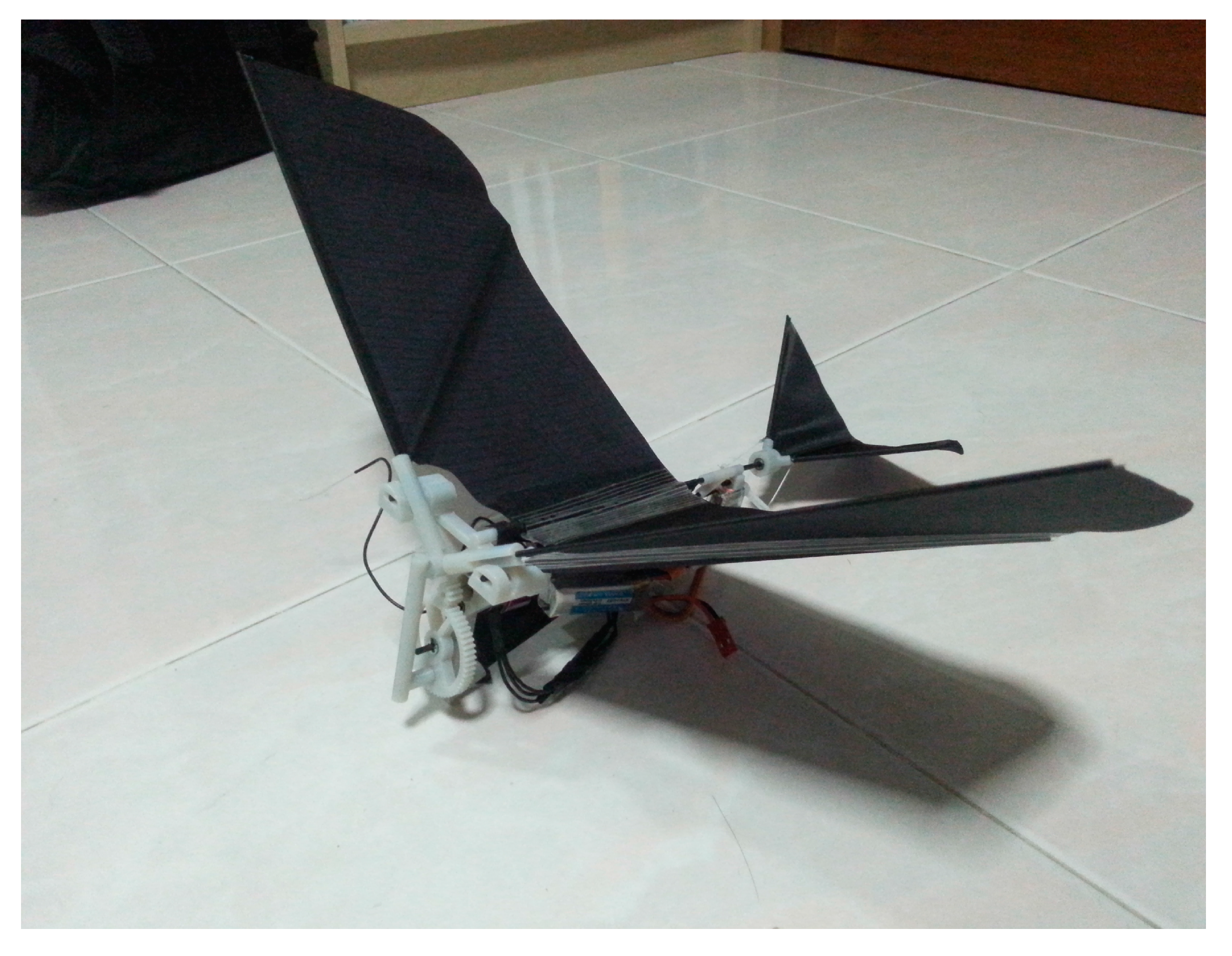
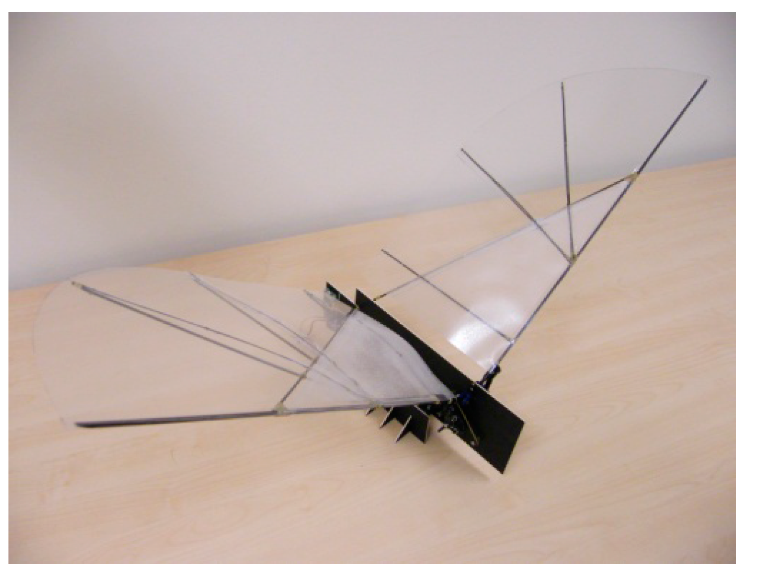
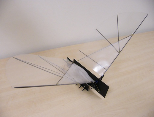
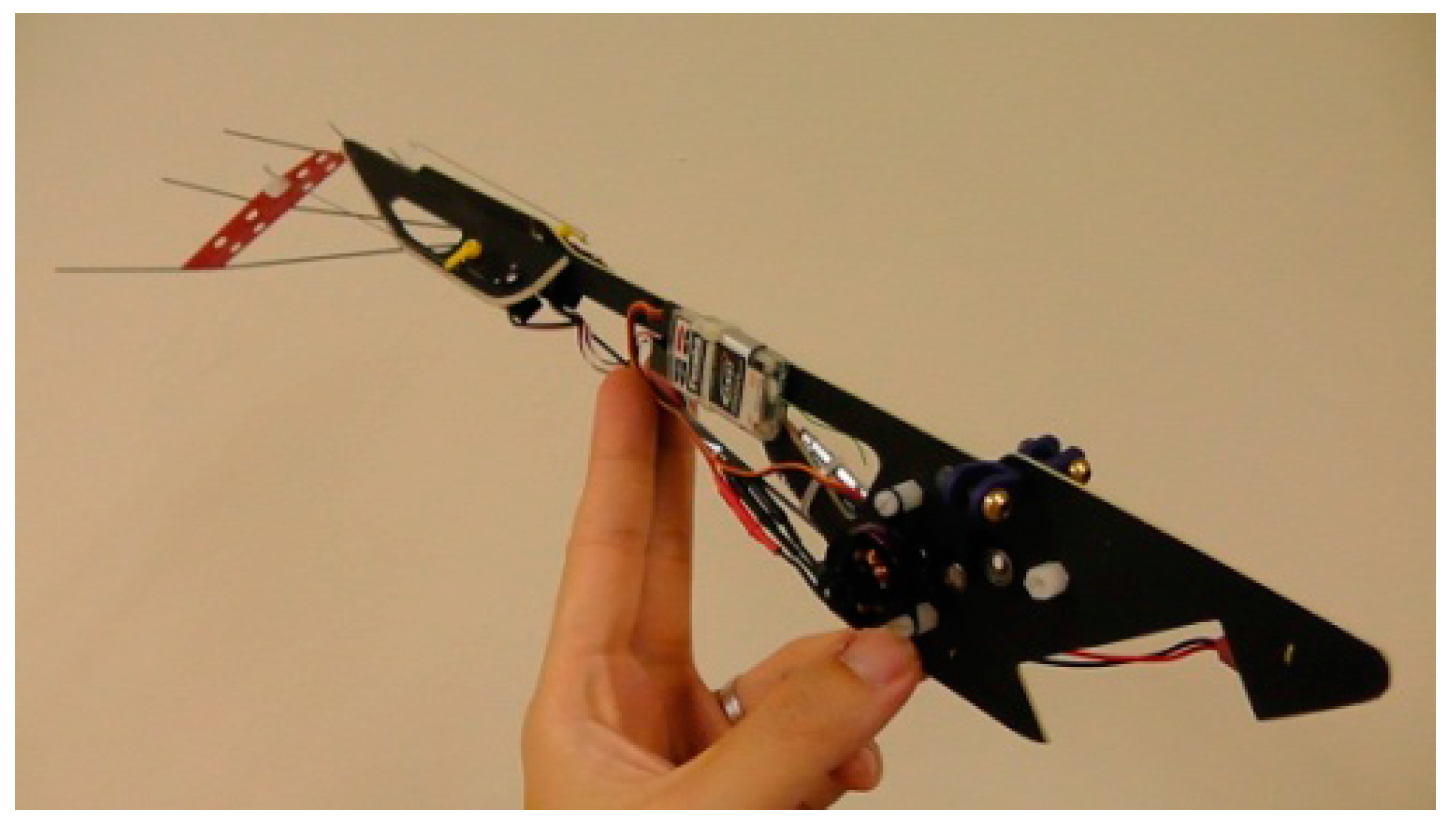
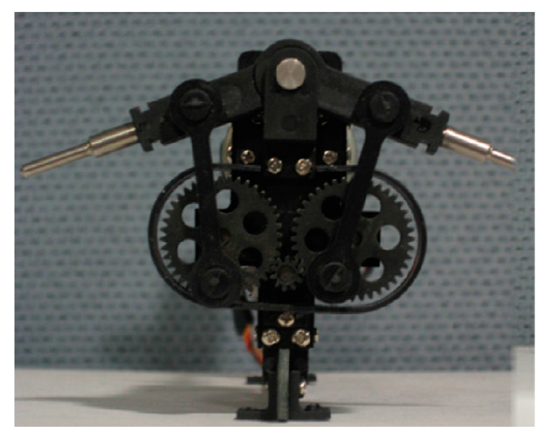
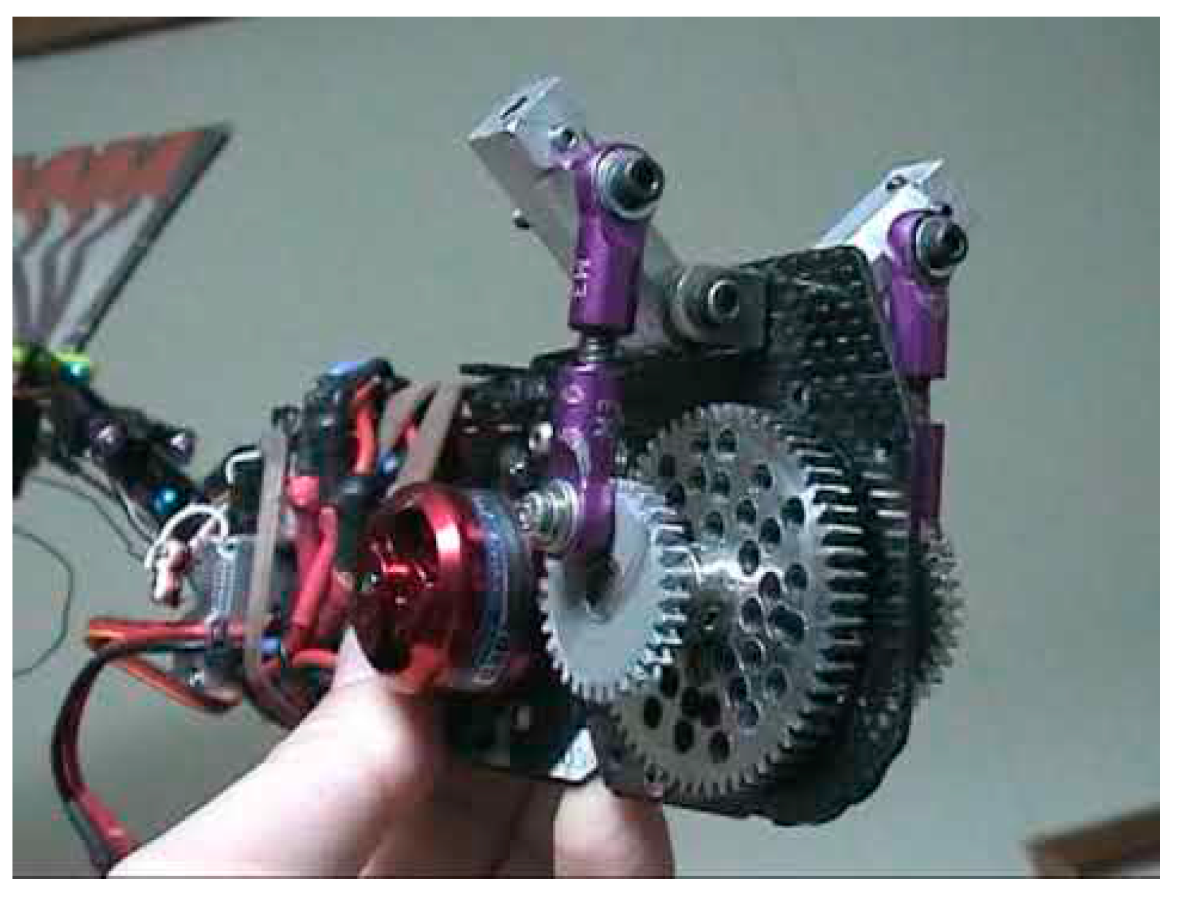
At University of Glasgow Singapore, we are developing the resonance type flapping wing models, as shown in
Figure 4 and
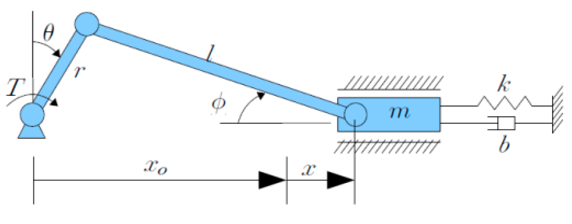
Figure 5 below. The proposed resonance type flapping wing will utilize the resonance phenomenon of a two-degree of freedom elastic system, that is, the wing is supported by the springs for flapping and feathering motions, being oscillated, at the resonance frequency of the system, as shown in
Figure 6 [
7]. The amplitudes of flapping and feathering motions and the phase angle between them are controlled by changing the amount of the damping.
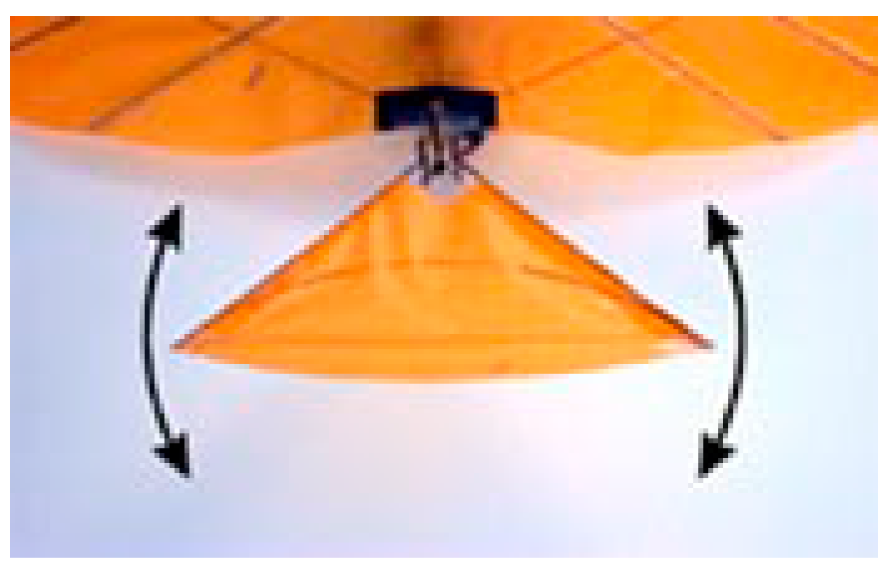
Figure 4.
Near-resonance ornithopter-like flapping wing model.
Figure 4.
Near-resonance ornithopter-like flapping wing model.
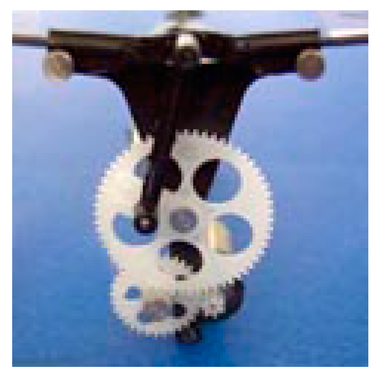
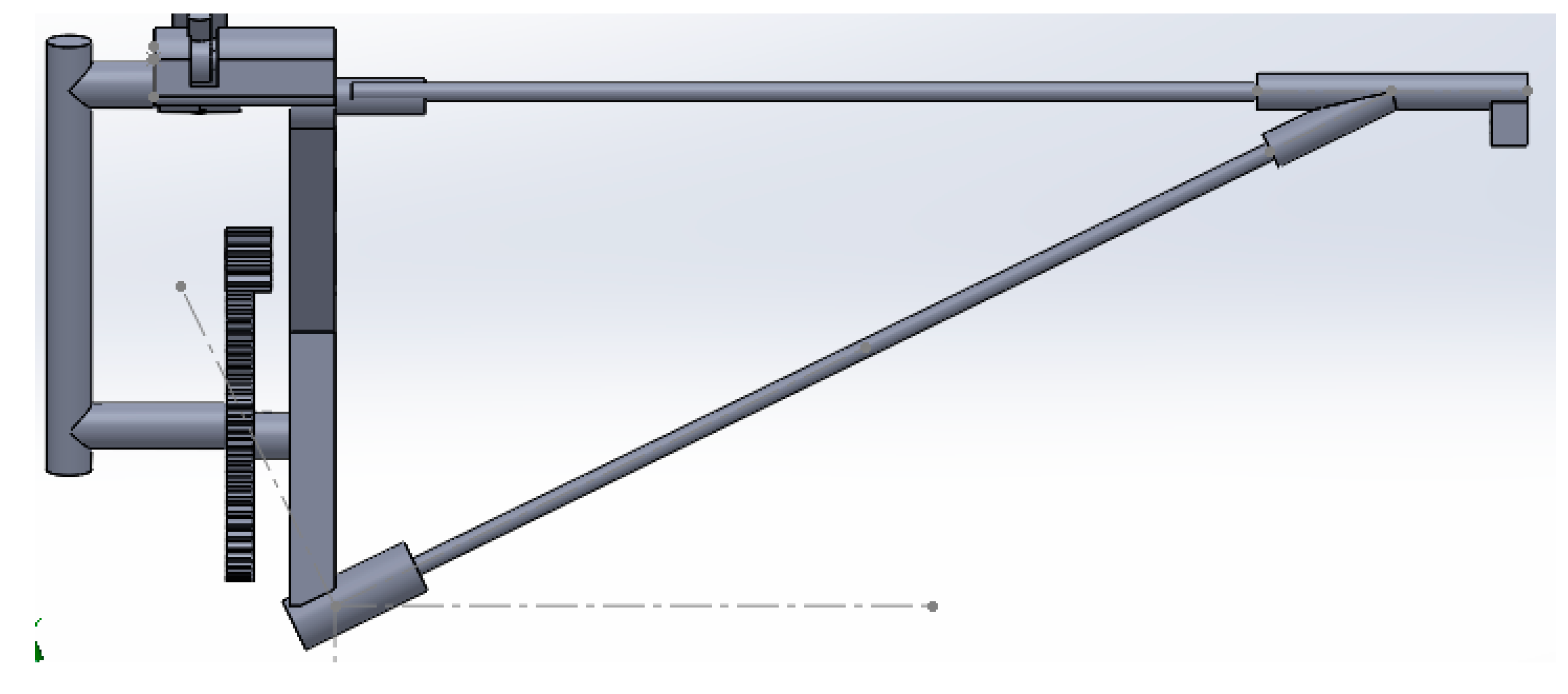
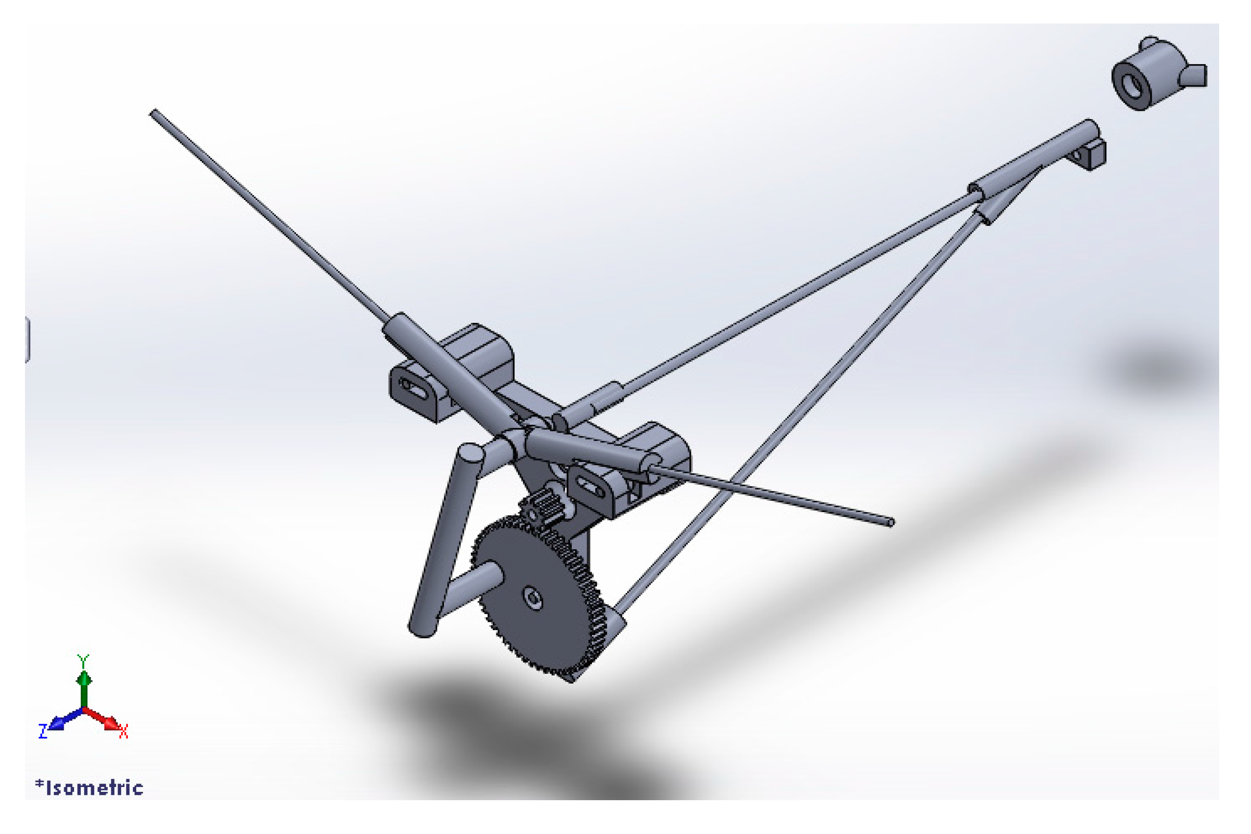
Figure 5.
Near-resonance ornithopter-like flapping wing mechanism.
Figure 5.
Near-resonance ornithopter-like flapping wing mechanism.
Figure 6.
Concept of resonance-type flapping mechanism [
7].
Figure 6.
Concept of resonance-type flapping mechanism [
7].
2. Computational Fluid Dynamics
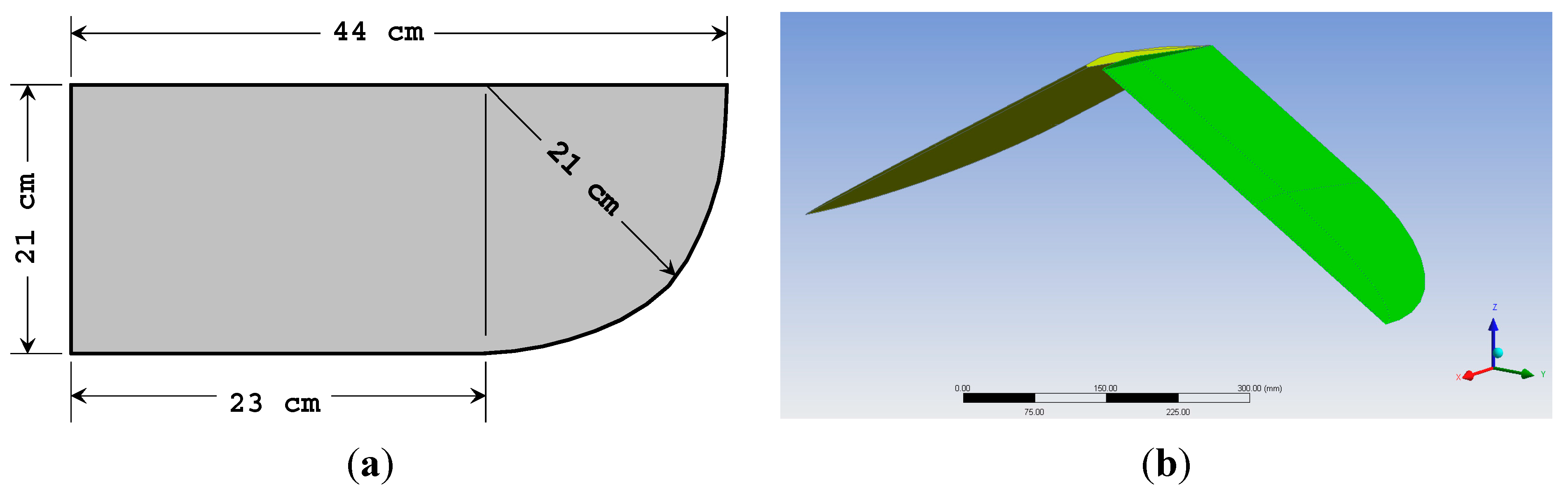
Firstly, we examined the flight dynamics as well as unsteady flow characteristics of the flapping wings for long-distance bird (e.g., albatross-like) by Computational Fluid Dynamics (CFD). These birds mostly flap their wings about their body axis (chordwise) with little change in twist (spanwise), as depicted in
Figure 7 [
8]. Therefore, for preliminary analyses, we apply only chordwise flapping to our model.
Figure 7.
(a) Simplified albatross flapping model with detailed geometry; (b) The wing is shown at −15 flapping position about its body (X) axis.
Figure 7.
(a) Simplified albatross flapping model with detailed geometry; (b) The wing is shown at −15 flapping position about its body (X) axis.
The flow around the flapping wing was simulated by using ANSYS Fluent
® (ANSYS Inc., Canonsburg, PA, USA) unsteady three-dimensional compressible Navier–Stokes equations. The machine that ran these problems was a 64 bit computer, Intel
® Core i7-2600 CPU at 3.4 GHz. It had eight processors at 16 GByte RAM. The geometric model of the albatross wing was the idealization of an albatross. The model wing had a wing span of 30 cm, mean wing chord length of 5 cm, a thickness of 2.5% of the mean wing chord length, as shown in
Figure 7. The computing domain extended to 50-chord lengths in all directions around the full model wing, and that, there were about 10
7 meshes of the tetrahedral type. The flow condition was unsteady transient flow, with the built-in Large–Eddy Simulation (LES) turbulence model.
The chosen wing’s geometry is shown in
Figure 7 below, of which Wingspan = 0.88, Wing Surface Area = 1.66 × 10
−1 m
2. This wing was originally set at rest. From past studies [
8,
9,
10,
11], the starting flapping frequency of the albatross wing was at 0.5 rad/s, corresponding to the reduced frequency
k (defined as ω
c/2
U∞) of 0.0025. The take-off speed of the albatross (
i.e., the freestream velocity in body-fitted coordinates),
U∞ was approximately 5 m/s. This gave the Reynolds number, based on chord
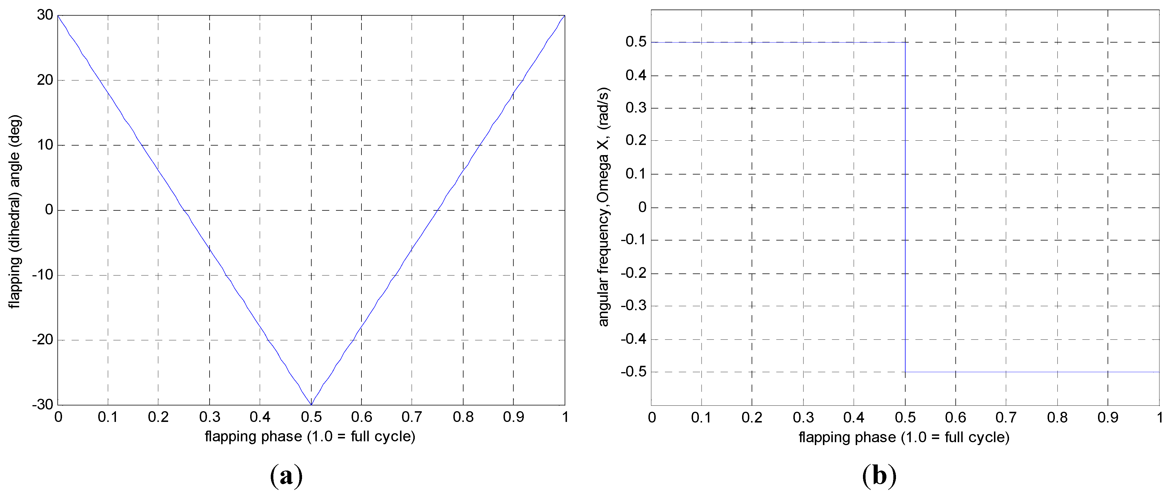
Re of 25,000. The wing was set to flap down and up about its body axis (chordwise), mimicking the start-up of the flapping motion (taking-off) and return to its initial position. The flapping (dihedral) angle changed from +30° to −30° in downstroke motion, and from −30° to +30° in upstroke motion. The input angular velocity about its chord (ω
x) is shown in
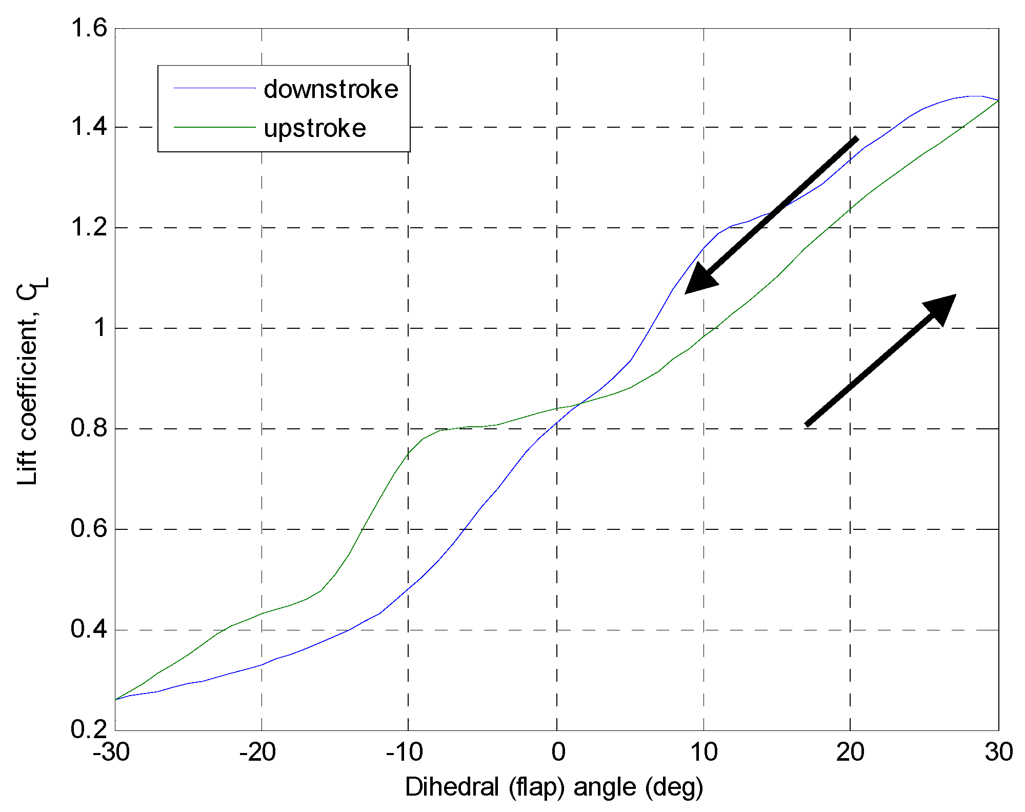
Figure 8. This downwards stroke in the first half of the cycle is the lift generation stroke, whereas the upwards stroke in the latter half of the cycle is the recovery stroke.
Figure 8.
(a) Flapping patterns for simplified albatross flapping model about its body axis (chordwise, ωx); and (b) the corresponding angular velocity, in each flapping cycle.
Figure 8.
(a) Flapping patterns for simplified albatross flapping model about its body axis (chordwise, ωx); and (b) the corresponding angular velocity, in each flapping cycle.
Initially, the wing was positioned at +30 degree dihedral angle. When the flapping motion started, the wing flapped downwards about its chord. At the outer half of the wing the flow separated from the wing, forming the start-up vortex which more visible at the top. There was flow separation at the trailing edge, closer to the root, at the area near the scapula (inboard of the wing). This leads to the creation of strong leading edge vortex [
8] as shown in
Figure 9, resulting in high lift (
Figure 10) at the beginning of this downstroke motion (at +30 degree dihedral angle).
Figure 9.
Vortex structure on the wing, shortly after start-up. The strong leading edge vortex on the upper part is clearly shown.
Figure 9.
Vortex structure on the wing, shortly after start-up. The strong leading edge vortex on the upper part is clearly shown.
Figure 10.
Lift coefficient during downstroke and upstroke motion of the wing.
Figure 10.
Lift coefficient during downstroke and upstroke motion of the wing.
As time goes on the flow separates across the wing, forming the strong leading edge vortex over the wing. In the inboard area near the trailing edge and scapula, the wake (shear layers) becomes more obvious. The lift is generated more by to this push-down motion of the wing. After mid-point (dihedral angle = 0°), the start-up vortex becomes bigger, and the flow separates from the wing entirely. At the leading edge near the alula (about half way between the root and the tip). The wake at the trailing edge of the wing also breaks up into outer and inner parts.
Figure 10 shows the lift coefficient in both downstroke and upstroke motion of the wing. The
CL values are obtained from directly from ANSYS Fluent
® software. The locus of the lift coefficient in both downstroke and upstroke motion resembles the inclined
Figure 8, as reported in many other literatures (e.g., [
4,
6,
8,
10,
12,
13,
14,
15]).
Figure 11 shows the lift coefficients derivatives with respect to flapping angle (d
CL/dα) this is for flight dynamics and control consideration.
Figure 11.
The lift coefficients derivatives with respect to flapping angle (dCL/dα), from CL.
Figure 11.
The lift coefficients derivatives with respect to flapping angle (dCL/dα), from CL.
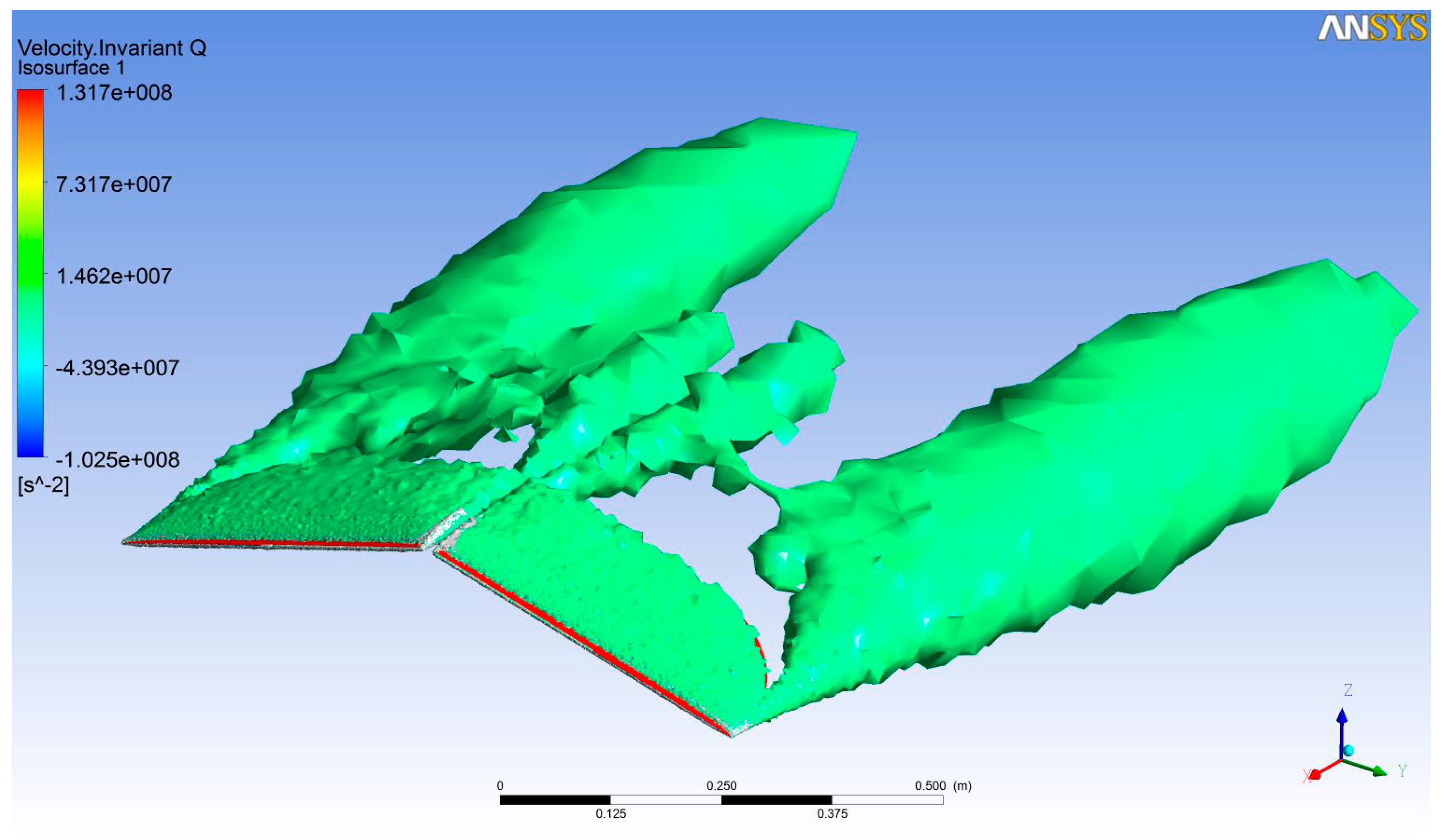
Figure 12 shows the vortex structure (invariant-Q) at dihedral angle = −15°. The leading edge vortex is dominant, covering the entire the wing. At the wing tip, the wingtip vortices is clear together with the wake behind the wing.
Figure 12.
Isosurface of the vorticity on the upper part of the albatross wing, at dihedral angle = −15°. The leading edge vortex covers the whole wing. The trailing edge vortices on both ends are outstanding.
Figure 12.
Isosurface of the vorticity on the upper part of the albatross wing, at dihedral angle = −15°. The leading edge vortex covers the whole wing. The trailing edge vortices on both ends are outstanding.
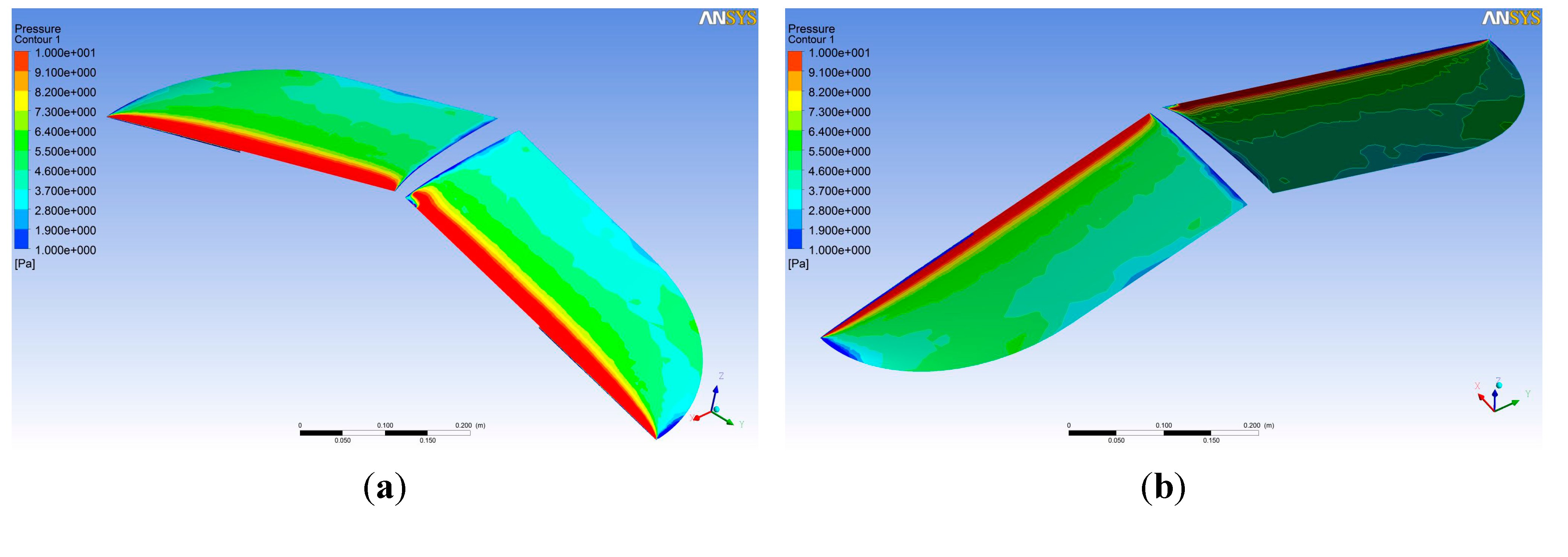
Figure 13 shows the surface pressure on the albatross wing also at dihedral angle = −15°. At the tip, there is region of lower pressure, shown in blue color. This is the area where the force is less generated. So, we deduce the albatross does maneuvering by flapping its entire wingspan at different amplitudes than using (flapping or twisting) its wing tip only.
Figure 13.
Surface pressure on the albatross wing at dihedral angle = −15°, upper surface (a) and lower surface (b).
Figure 13.
Surface pressure on the albatross wing at dihedral angle = −15°, upper surface (a) and lower surface (b).
These unsteady flow results show that the albatross generates lift on its wing mainly by vortex lift mechanism, as reported in other literatures ([
15,
16,
17,
18,
19,
20,
21,
22,
23,
24,
25,
26,
27,
28]). The lift is generated by flapping its entire left and right wings at different amplitudes than using (flapping or twisting) its wing tip only. Any additional spanwise flapping (pitching) will fine-tune its position inflight. Therefore, for the sake of developing flapping-wing like MAV (next section), we could introduce only the chordwise flapping motion and neglect the spanwise flapping motion.
3. UGS Flapping Wing MAV Prototypes 1
3.1. Mechanism
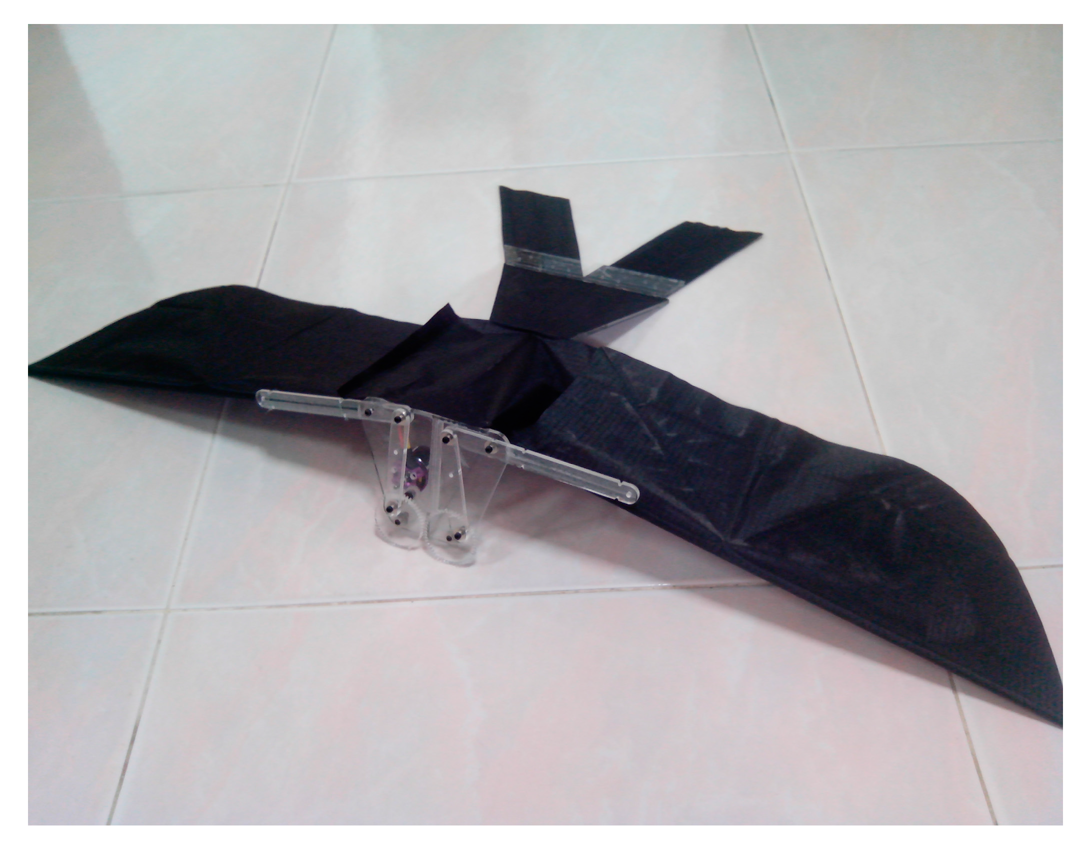
A flapping wing mechanism capable of producing flapping motion is designed and built. An overall view of this mechanism with a length of 46.5 cm can be seen in
Figure 14. This figure also depicts the relative scale between the flapping mechanism and the tail. This mechanism is powered by a small brushless motor and has a maximum output of 55 W that weight only 15 g. A Lithium–Polymer battery that has a nominal voltage of 7.4 V is required to drive the motor.
Figure 14.
Overall view of entire flapping mechanism.
Figure 14.
Overall view of entire flapping mechanism.
A complete set of computer aided design (CAD) models are developed to ensure an accurate fit between parts. The software used to generate CAD models is done using CATIA (Computer Aided Three-dimensional Interactive Application (Dassault Systèmes, Cedex, France). The various parts of the mechanism can be seen in
Figure 15 and
Figure 16.
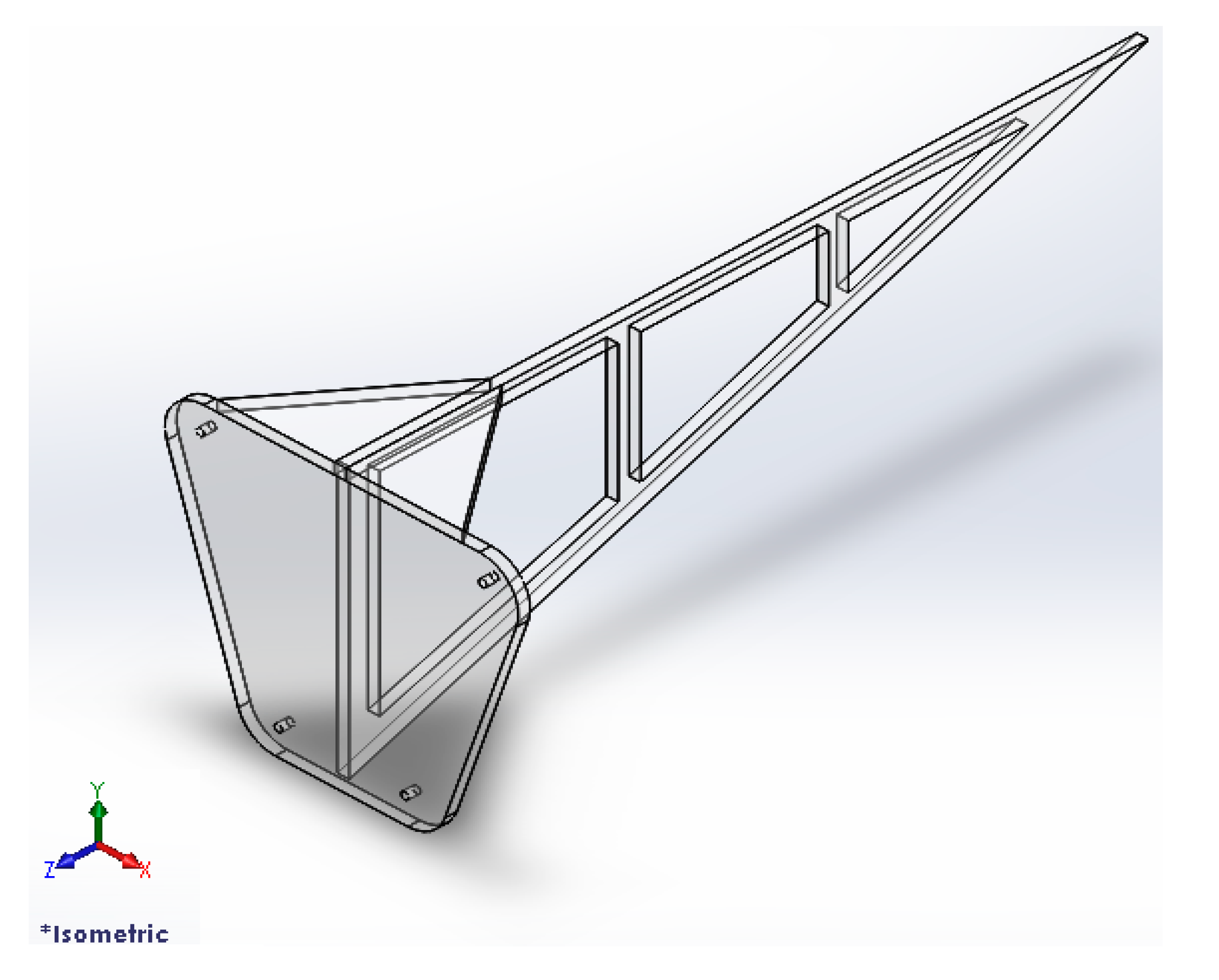
Figure 15.
Left side view of flapping mechanism (computer aided design (CAD) model).
Figure 15.
Left side view of flapping mechanism (computer aided design (CAD) model).
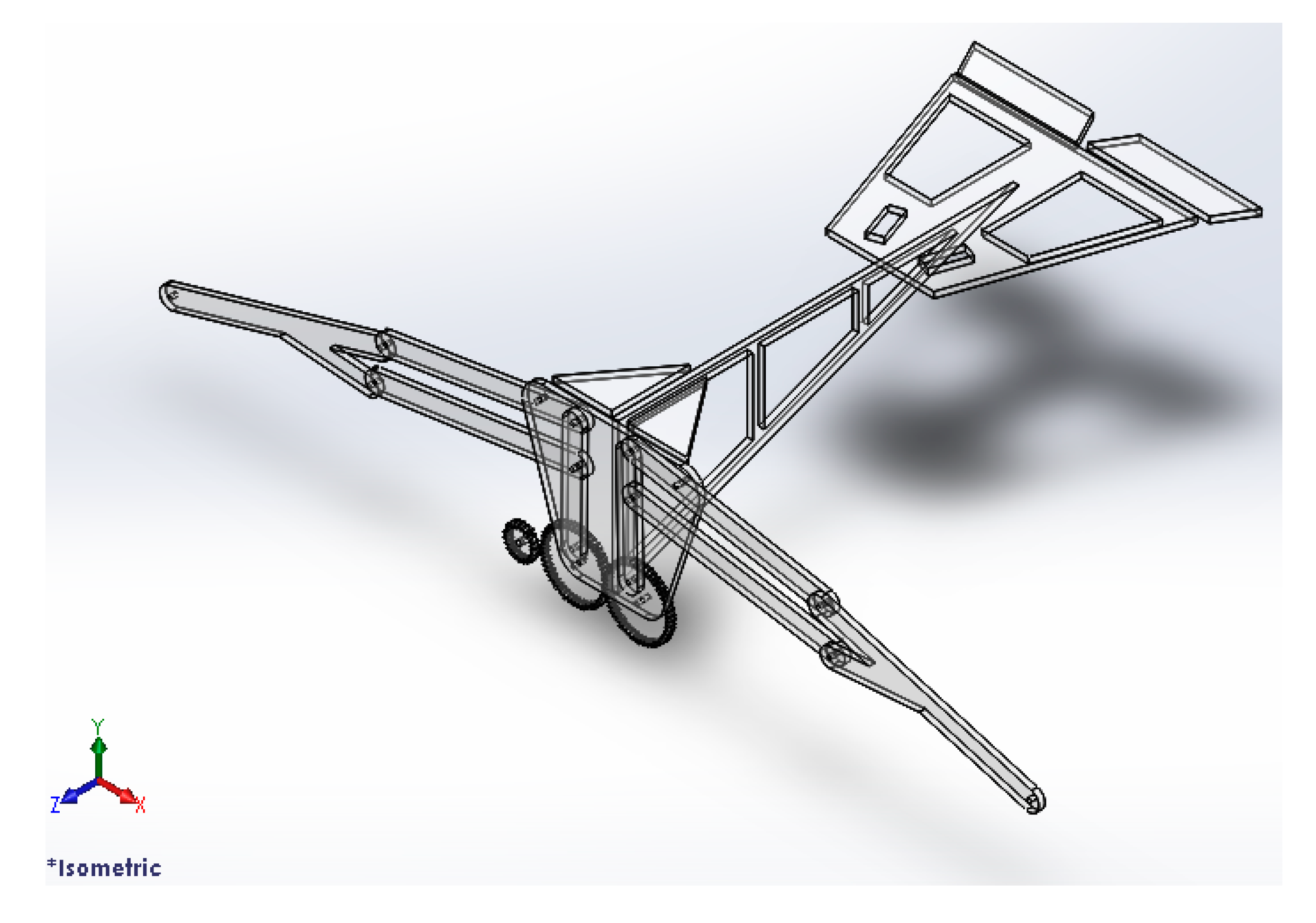
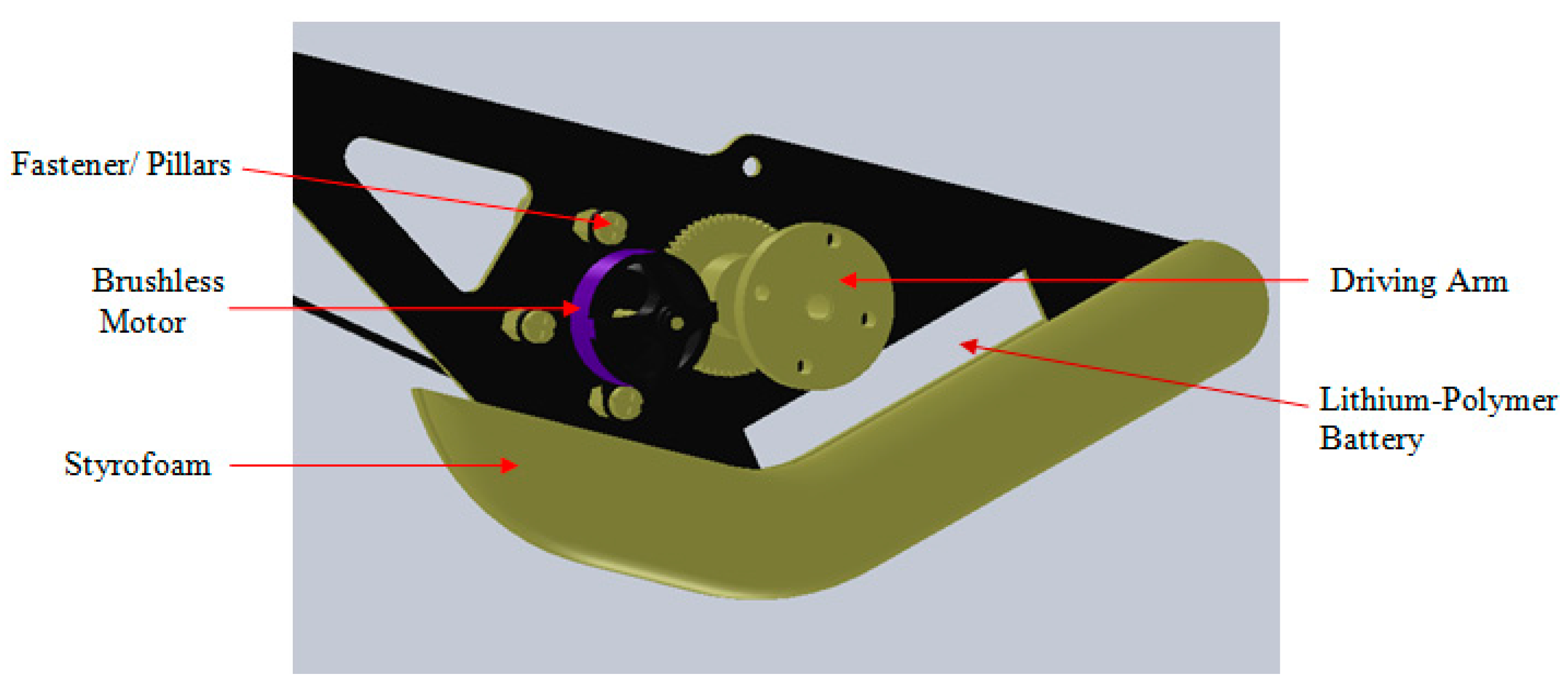
Figure 16.
Right side view of flapping mechanism (CAD model).
Figure 16.
Right side view of flapping mechanism (CAD model).
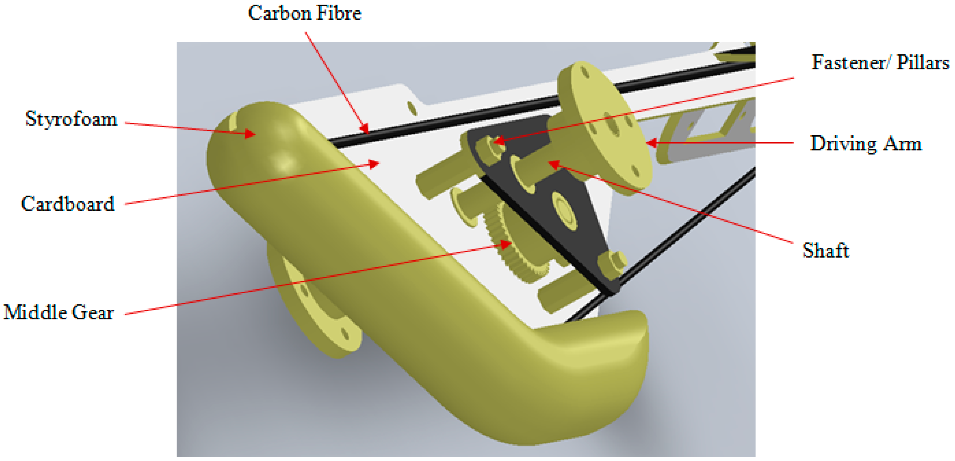
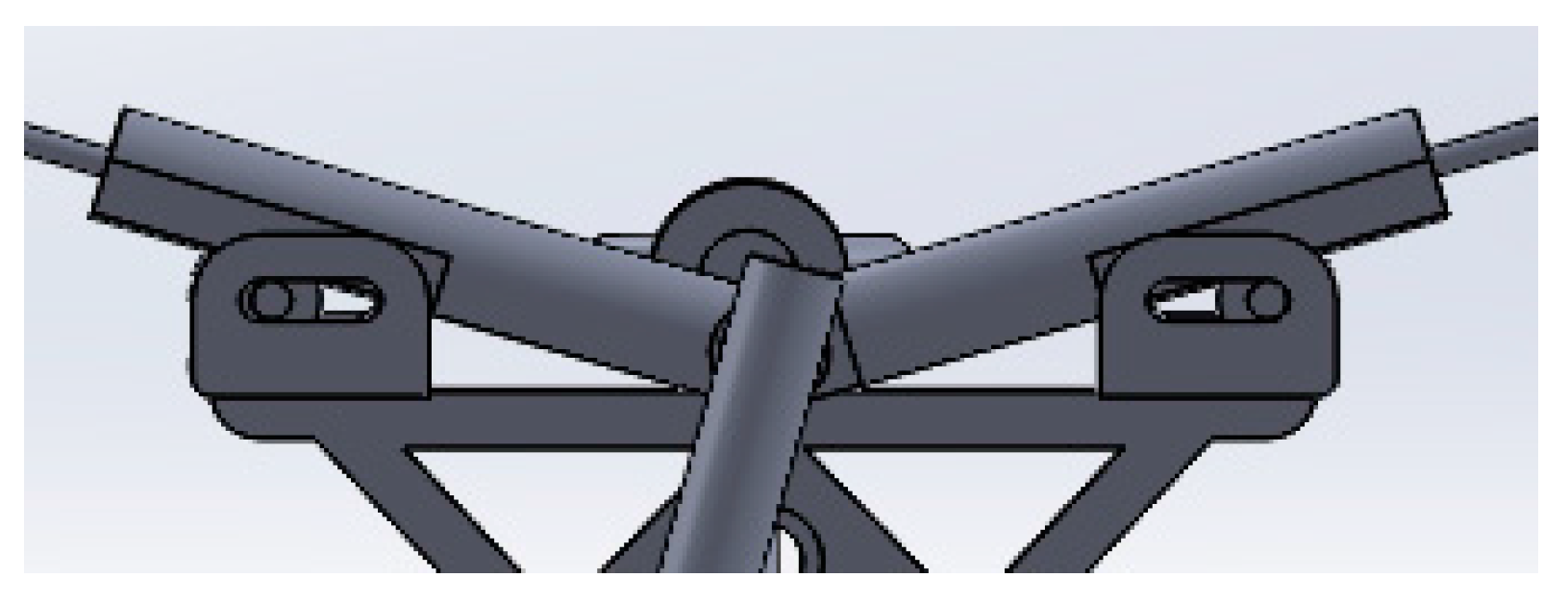
From
Figure 16 the brushless DC motor is mounted onto the fuselage of the ornithopter using three nylon pillars. The motor is powered directly by Lithium–Polymer battery. In order for both wings to flap in sync, a single shaft is installed and attached onto both sides of the driving arms. The driving arms are then attached along with the wings. The Styrofoam at the front side of the fuselage is used to reduce the impact if the ornithopter would to fall. Carbon fiber sticks are used to strengthen the fuselage to prevent twisting and bending stress when it flaps. The Lithium–Polymer battery is placed in the front fuselage, so that the center of gravity for the prototype is achievable.
It is important to make the mechanism as light as possible, therefore the lightest, and most cost effective materials available are considered. Initially, carbon fiber which is strong and light-weight is one of the considerations. However, there are limited resources to manufacture and cut into the desired shape. As a result, the next option is to use cardboard, which is equivalent light-weight and easy to cut but not as durable as carbon fiber. Each component and sub-assembly for this ornithopter is weighted as shown in
Table 1.
Table 1.
Weight of each Component and Sub-assembly.
Table 1.
Weight of each Component and Sub-assembly.
| Component and Sub-assembly | Weight (g) |
|---|
| Kypom Lithium–Polymer Battery | 29 |
| Hacker A10-A12s Brushless Motor | 15 |
| Futaba R6004FF Receiver and Castle Creation Thunderbird 9 Electronic Speed Controller | 13 |
| 2× Tahmazo TS-1002 Servo Motor | 8 |
| 2× Driving Arm and Linkage | 8 |
| Tail Structure | 11 |
| Main Shaft | 6 |
| Main Gear | 7 |
| Middle Gear | 5 |
| Pinon Gear | 1 |
| Fuselage | 15 |
| Fasteners, Screws, Nuts and Wheel-Locks | 7 |
| Wings | 35 |
| Total Weight | 160 |
3.2. Wing Construction
In the design and construction of any ornithopter, one of the most crucial components governing overall performance is the wings. Especially in a flapping-wing air vehicle, the wings are vital to flight performance aspects including endurance, speed, manoeuvrability, and many other useful behaviors. An effective ornithopter must have wings capable of generating both thrust, the force that propels the craft forward, and lift, the force, perpendicular to the direction of flight, that keeps the ornithopter airborne. These forces must be strong enough to counter the effects of drag and the weight of the ornithopter. The wings produce lift and thrust primarily due to their ability to change shape during the flapping motion. As the wing is accelerated, aerodynamic loading causes the wing to deform. The result is a fairly large camber change of the wing that results in the normally flat plate shape changing to an airfoil shape. The aerodynamic loading also produces large angles of attack that create thrust. When these two effects are combined, the airfoil wings are placed in a moving airstream, thus creating a flight sustaining lift force.
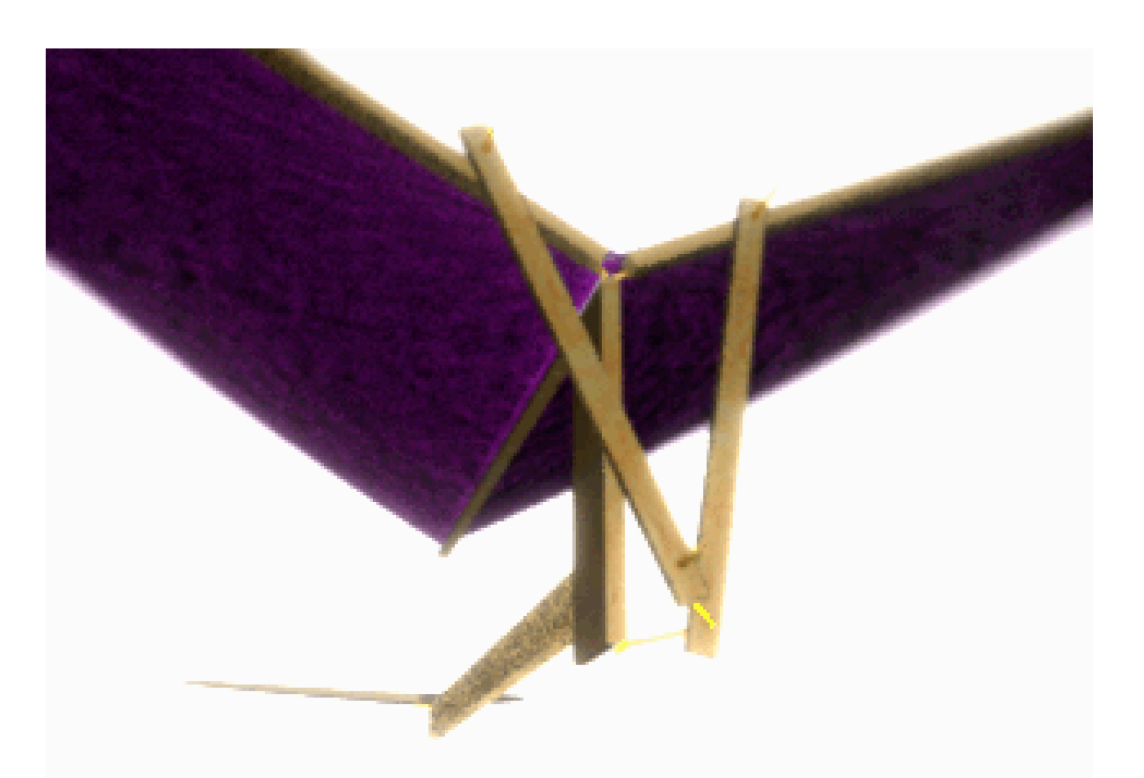
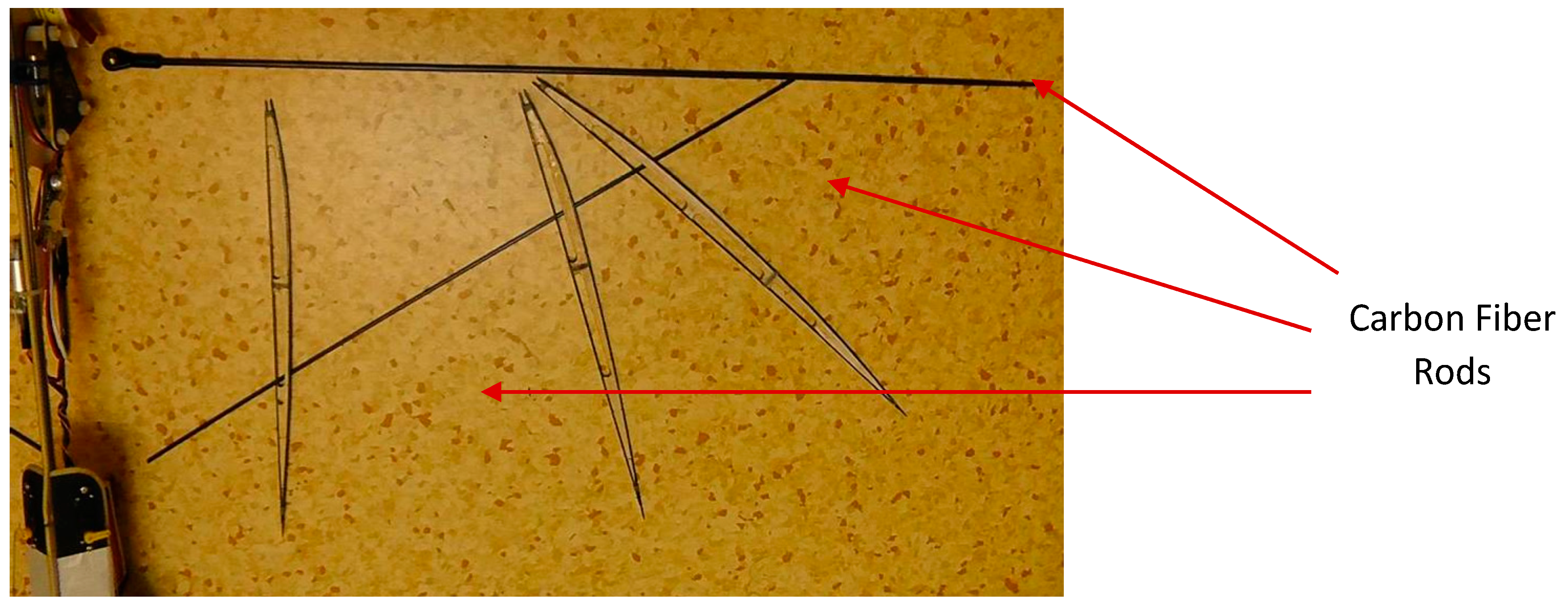
In order to achieve the desired flexibility and minimum weight, carbon fiber rods are used in the construction of the wings to provide a lightweight and stiff structure of spars, similar to the skeletal structure of a flying animal as shown in
Figure 17. Ornithopters do not necessarily act like flying animals in flight. Typically flying animals have thin and cambered wings to produce lift and thrust. Ornithopters with thinner wings have a limited angle of attack but provide optimum minimum-drag performance for a single lift coefficient. The Pigeon Hawk has the closest characteristic as our ornithopter prototype, with the weight of 181.3 g and therefore the dimension of the constructed wing is as shown in
Figure 18 [
9].
There are two different materials used for the wings. The first material used is a polyester film made from stretched Polyethylene Terephthalate (PET). It has high tensile strength, and is commonly used in ornithopter flights. The second material used is Orcon, which is a better material than PET film. The Orcon is a strong and ultra-lightweight material. Unlike other plastic and mylar-like films, Orcon will not continue to tear even a small slit is detected.
Figure 17.
View of wing skeletal structure—one half.
Figure 17.
View of wing skeletal structure—one half.
Figure 18.
Dimension of the constructed wing [
9].
Figure 18.
Dimension of the constructed wing [
9].
Three different types of wings designs with various material and skeletal structure are fabricated. The first type is called PET cambered thin wing with a skeletal structure as shown in
Figure 19.
Figure 20 shows the PET cambered thin wing that is fabricated using the PET material.
Figure 19.
Skeletal structure for polyethylene terephthalate (PET) cambered thin wing (CAD Model).
Figure 19.
Skeletal structure for polyethylene terephthalate (PET) cambered thin wing (CAD Model).
Figure 20.
PET cambered thin wing.
Figure 20.
PET cambered thin wing.
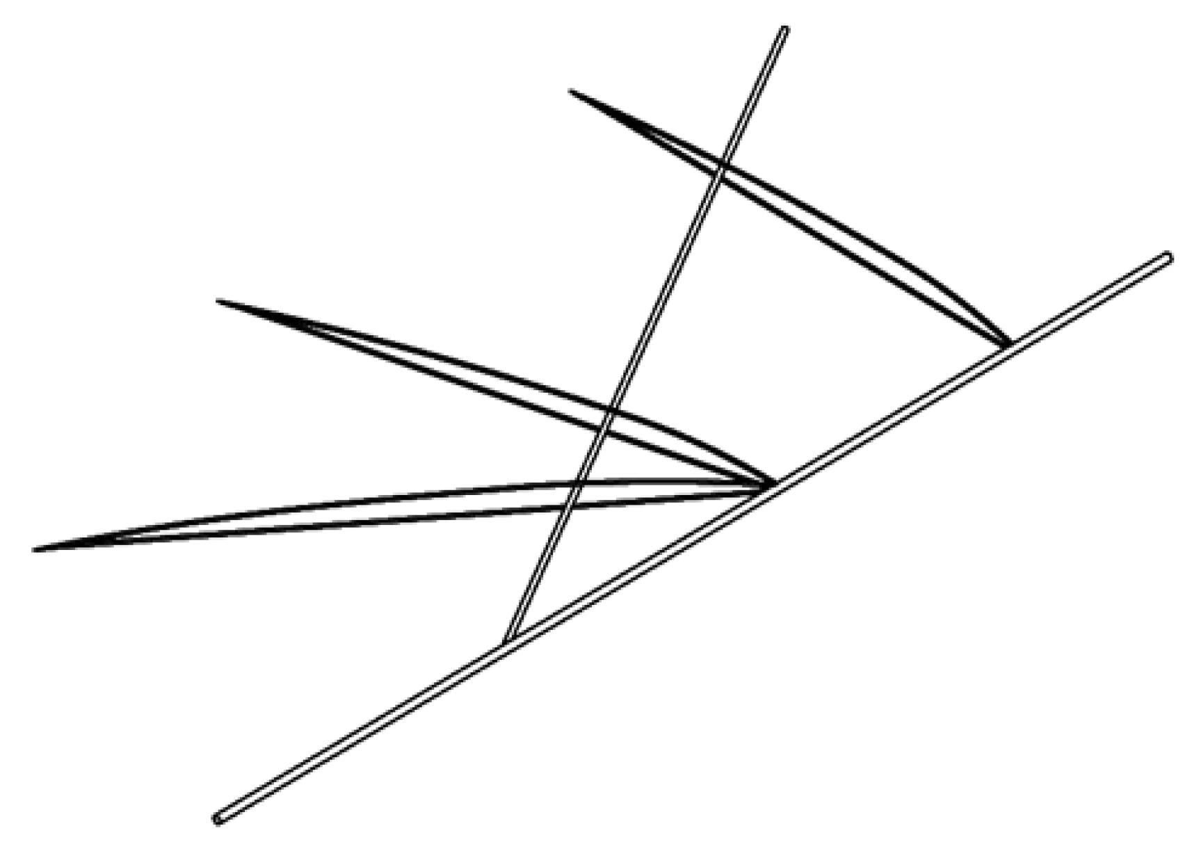
The second type of wing is called Orcon cambered thick wing with a skeletal structure as shown in
Figure 21.
Figure 21.
Skeletal structure for Orcon cambered thick wing (CAD model).
Figure 21.
Skeletal structure for Orcon cambered thick wing (CAD model).
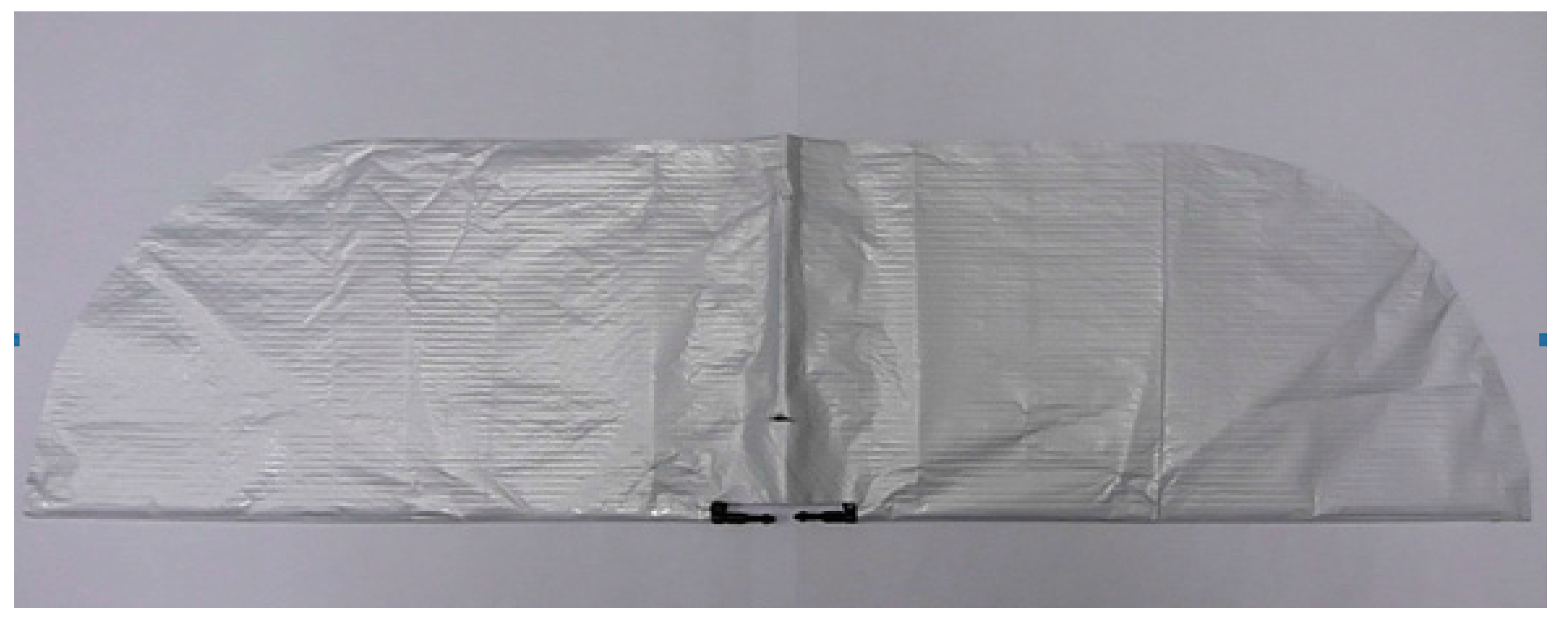
Figure 22 shows the Orcon cambered thick wing that is fabricated using the orcon material.
Figure 22.
Orcon cambered thick wing.
Figure 22.
Orcon cambered thick wing.
The first two types of wings that are mentioned above are designed to have cambered due to the advantages of the increased lift-drag ratios and more desirable stall characteristics. It has a higher lift coefficient than the symmetrical airfoil. The top edge of the airfoil is shaped differently than the bottom edge, which changes the way air flows over it. This causes the air to move faster, which creates more lift.
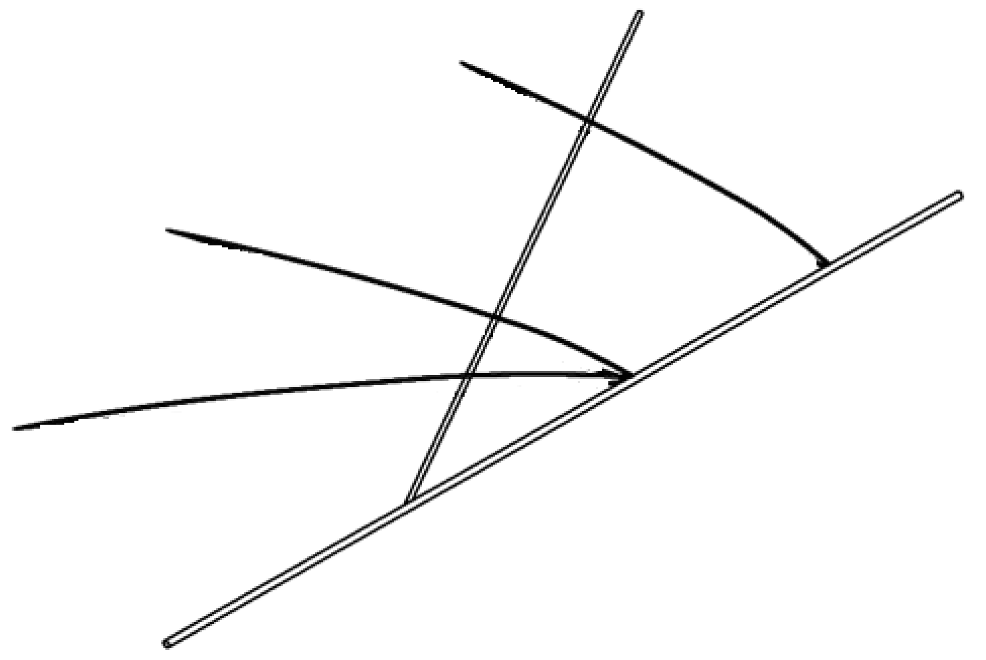
The third type of wing is designed with a thin airfoil, called the Orcon flat wing with a skeletal structure as shown in
Figure 23.
Figure 23.
Skeletal structure for Orcon flat wing (CAD model).
Figure 23.
Skeletal structure for Orcon flat wing (CAD model).
The lift coefficient is sacrificed for a lighter weight. Lighter weight can produce smaller inertia of the wing and thus faster flapping speed, which will in turn increase air velocities.
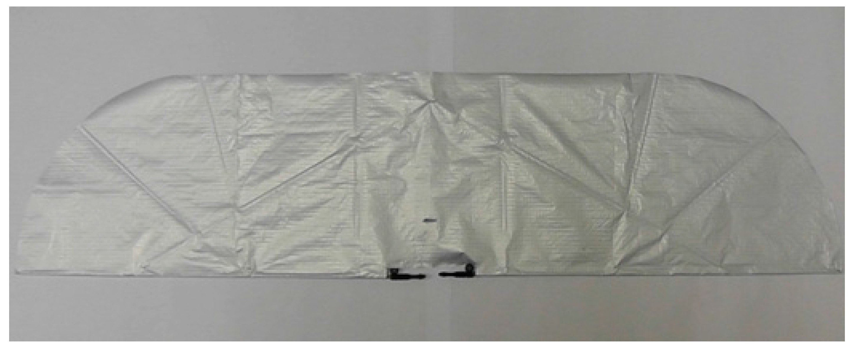
Figure 24 shows the Orcon flat wing which is fabricated using the orcon material.
Figure 24.
Orcon Flat Wing.
Figure 24.
Orcon Flat Wing.
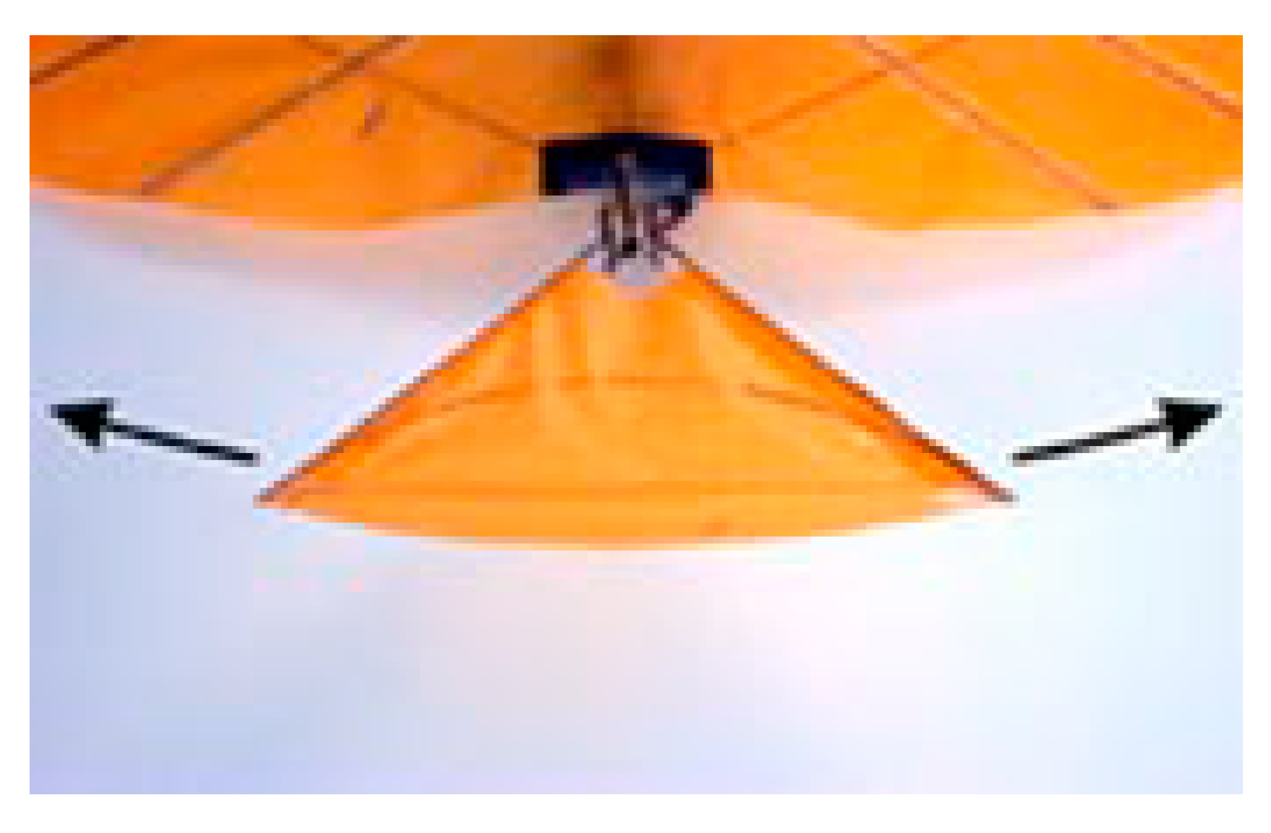
3.3. Center of Gravity (CG)
The center of gravity may be defined as the average location of the mass distribution. It is a point in space where, for the purpose of various calculations, the entire mass of a body may be assumed to be concentrated. The center of gravity is an important point on an aircraft, which significantly affects the stability of the aircraft to fly safely. Therefore the center of gravity must fall within specified limits to ensure the ornithopter is stable. A simple method is adopted to determine the CG of the prototype ornithopter and that is to hang the prototype ornithopter from the ceiling using a kevlar thread as shown in
Figure 25, the CG is obtained when the prototype ornithopter is equilibrium and balanced horizontally with the ground level.
Figure 25.
Equilibrium position of the prototype ornithopter.
Figure 25.
Equilibrium position of the prototype ornithopter.
3.4. Lift and Thrust Force Measurement
The experimental apparatus utilized by the authors include a force measuring load cell, a test assembly, and video recording is also taken of the mechanism with the various wing designs flapped. This section also presents the calibration of the load cell to ensure that the data measured is accurate. After the calibration is done, the data unit of the force measurement is converted from electrical signal into gram or Newton unit.
3.4.1. Force Measuring Load Cell
The first and most important component of the force measurement system is the transducer. A load cell is a transducer that is used to convert the loads generated by the flapping wing into voltage signal for subsequent recording and processing. Through a mechanical arrangement, the force being sensed deforms a strain gauge. In most cases, four strain gages are used to obtain maximum sensitivity and temperature compensation. Two of the gauges are usually in tension, and two in compression. A strain gauge is a series of thin wire filaments wound in a serpentine fashion and placed in a Wheatstone Bridge configuration.
Voltage is supplied to the strain gauge and as a load is applied to the wire filaments, they will either elongate or shrink, changing the resistance in the wires. This variation in resistance results in different input and output voltages from the strain gauge. The difference in voltage is then used to calculate the strain.
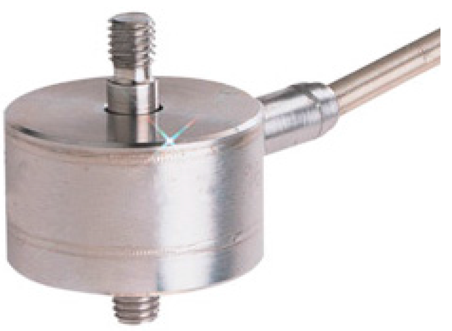
It should be noted that the expected measured thrust and lift are very small,
i.e., around 0.1–1.0 N. The force measuring load cell utilized in this project is an Omega Engineering, LCMFD-20N load cell which is shown in
Figure 26. This LCMFD-20N load cell is small in size and capable of providing highly accurate readings of a 2041 gram capacity. According to Omega Engineering’s website (
www.omega.co.uk) on technical specification, this LCMFD-20N load cell has its accuracy (linearity and hysteresis combined) and uncertainty of 0.15% FSO (Full-Scale Output),
i.e., 0.03 N (0.15% of 20 N). Since, the accuracy and uncertainty numbers are about 0.03 N (order of 10
−2),
i.e., about 1 order of magnitude less of the expected minimum measured thrust and lift values around 0.1–1.0 N (order of 10
−1 to 1), this is acceptable. In addition, this model is selected because of its high frequency resonant characteristics, minimal contamination from off-axis loads, and robust overloading tolerances.
Figure 26.
Omega engineering, LCMFD-20N load cell.
Figure 26.
Omega engineering, LCMFD-20N load cell.
The load cell measures the forces when the prototype ornithopter flaps its wing on a force balance by converting these forces into electric signals, which will be displayed on the Omega DP41 digital panel.
3.4.2. Test Assembly
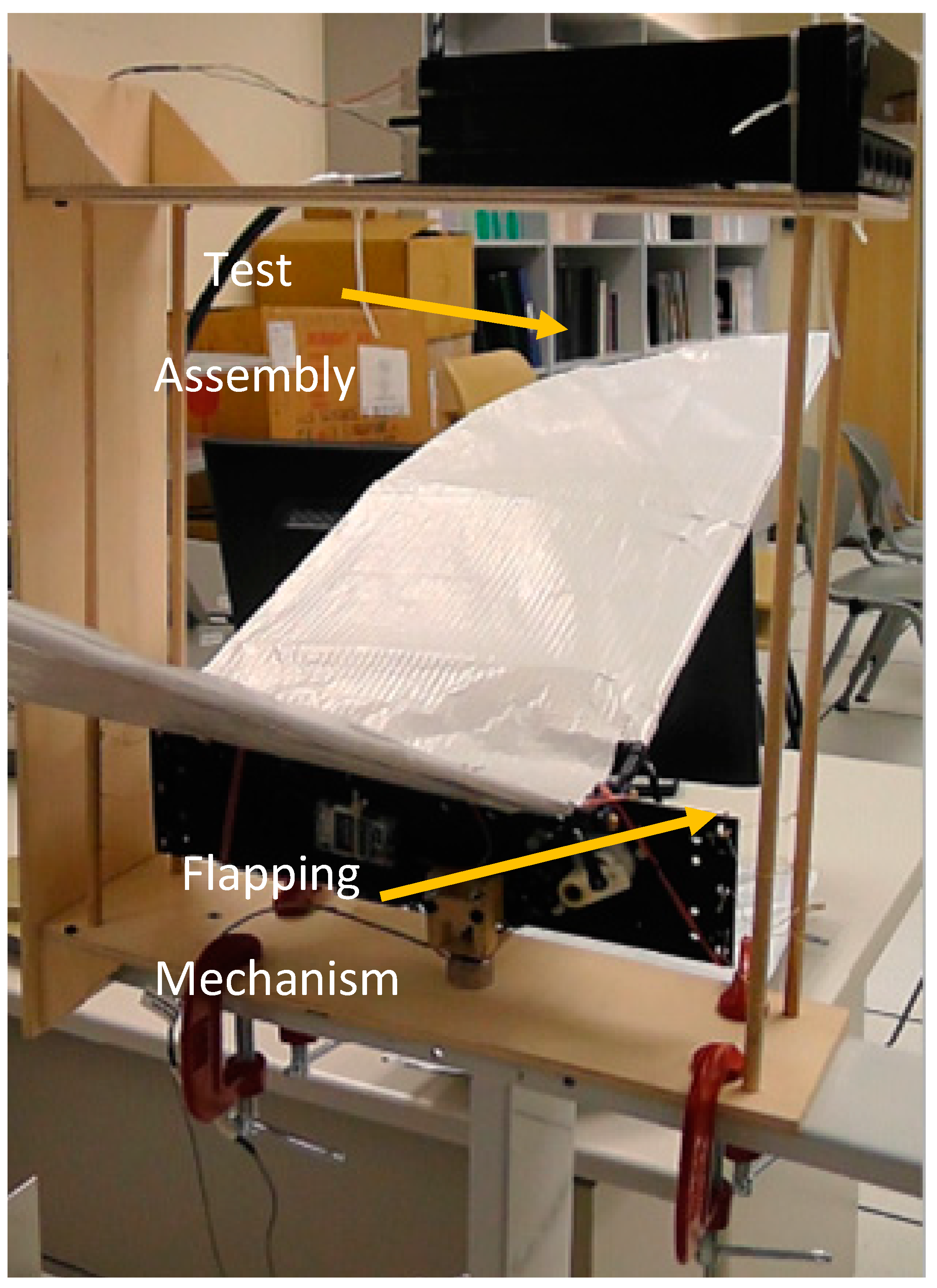
One of the challenges in this project is to design and build a test assembly made of pinewood in which the mechanism could flap and also measure both lift and thrust forces with the use of the load cell. A flapping mechanism in the test assembly can be seen in
Figure 27. The position of the load cell is mounted to a fixed point on the test assembly, and by rotating the test assembly vertically together with the respective kevlar thread connected to the flapping mechanism, this testing assembly could measure the lift and thrust forces generated by the flapping mechanism. In addition, this only allow the flapping mechanism to move in either ±
X axis, which measures the thrust force, or ±
Y axis, which measures the lift force.
G-clamps are used to clamp the test assembly to a metal stand. This allows the wing tests to be done at a distance above ground so that we do not take into account the ground effects when the wings are flapping.
Figure 27.
Test assembly and flapping mechanism.
Figure 27.
Test assembly and flapping mechanism.
3.4.3. Lift and Thrust Forces Measurement Methods
As the objective of this project is to characterize the different lift and thrust generation performance from three different wing designs, namely PET cambered thin wing, Orcon cambered thick wing and Orcon flat wing, different thrust measurement techniques will be investigated. This section presents the various methods for testing the lift and thrust generation of the prototype ornithopter. Kevlar thread is used extensively in this project as this innovative thread is light and its strength to weight ratio makes it five times as strong as steel. Kevlar thread does not break instantly but progressively, providing a non-catastrophic failure mode allowing a margin of safety.
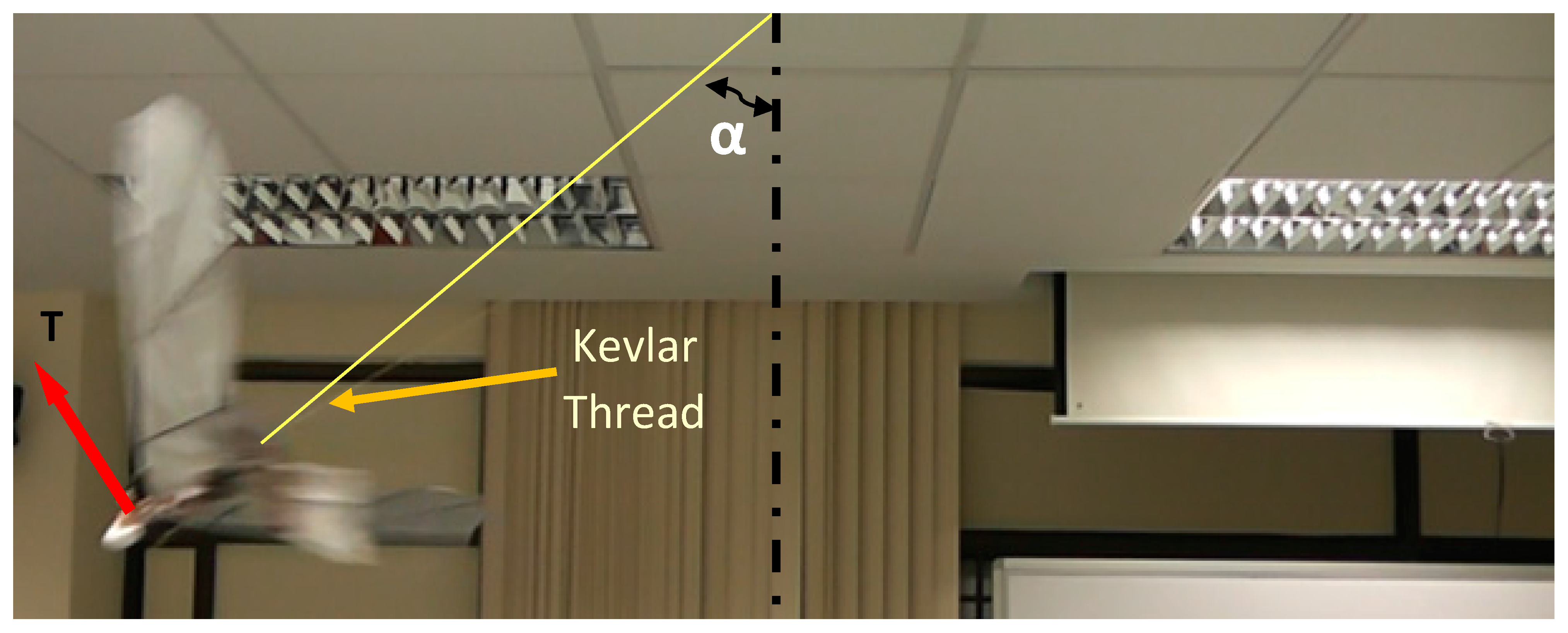
Thrust Measurement by Swing Method
In this method, the prototype ornithopter is tightly attached to one end of the connecting kevlar thread and the other end is attached to the ceiling, making the body axis of the prototype ornithopter perpendicular to the connecting kevlar thread, as shown in
Figure 28. The three different pairs of wings are tested using this method to measure the thrust produced.
Figure 28.
Thrust measurement of swing method.
Figure 28.
Thrust measurement of swing method.
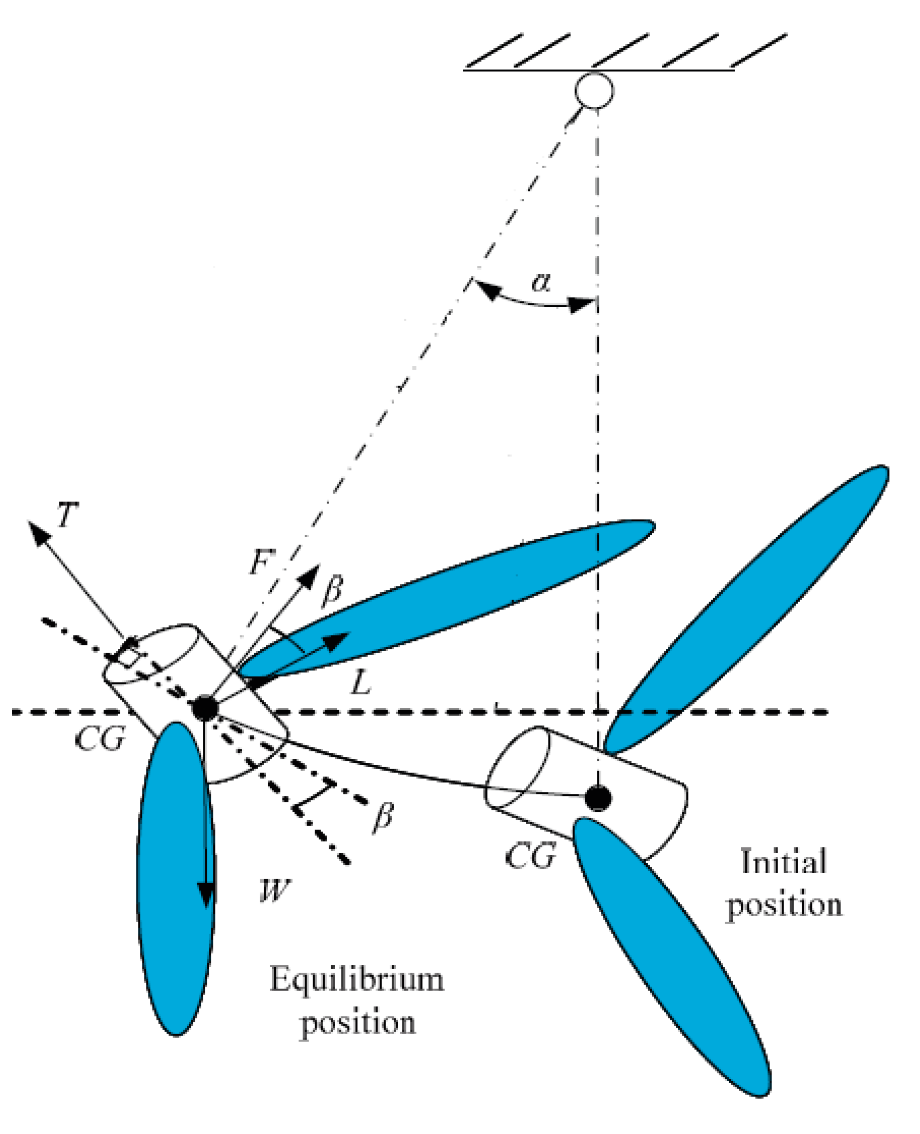
When the prototype ornithopter is excited, it produced thrust and moved to an equilibrium position. Assuming that all forces act at the center of gravity of the prototype ornithopter as shown in
Figure 1, the equilibrium equation of the ornithopter after applying voltage is
where
T,
F,
L,
W are the thrust, tension of the connecting kevlar thread, side force, and weight of the prototype ornithopter, respectively.
T and
L are two components of the resultant aerodynamic force projected on the ornithopter’s body axis and the direction perpendicular to the ornithopter’s axis, respectively. The equilibrium condition in vertical and horizontal directions can be modified as follows:
where α and β are the swing angle of the connecting kevlar thread and the body angle of the ornithopter, respectively, as shown in the
Figure 29.
Figure 29.
Force diagram of swing test.
Figure 29.
Force diagram of swing test.
The body angle β is the angle between the ornithopter’s body axis and the line perpendicular to the connecting kevlar thread. By eliminating the tension
F in Equation (2), the thrust is calculated as follows:
Hence, if the ornithopter’s body axis is zero (β = 0°;
i.e., the body axis of the ornithopter is perpendicular to the connecting kevlar thread), the thrust at equilibrium can be calculated by:
Load Cell Thrust Measurement Experiment Setup
In this thrust measurement setup, the mounting orientation of the load cell is shown in
Figure 30. The load cell is fixed onto the test assembly in a stationary position. The front portion of the flapping mechanism is attached to the load cell while the top and bottom segments of the flapping mechanism are tied vertically to the test assembly with the use of kevlar thread. Thus, after mounting the pair of wings onto the flapping mechanism and turn on the motor, the flapping mechanism is constrained by the kevlar thread so that it is only capable of motion in the
X-direction.
Motion in the +
X direction represented thrust, while motion in the −
X direction represented drag. As the flapping mechanism is moving in the +
X direction, the load cell is under compression and therefore the readings displayed on the digital panel are negative values as discussed in
Section 2 Load Cell Calibration. In this configuration, the thrust produced for the three different wing designs at three different flapping frequencies will be measured and then recorded in an Excel spreadsheet.
Figure 30.
Side view of the load cell thrust measurement setup.
Figure 30.
Side view of the load cell thrust measurement setup.
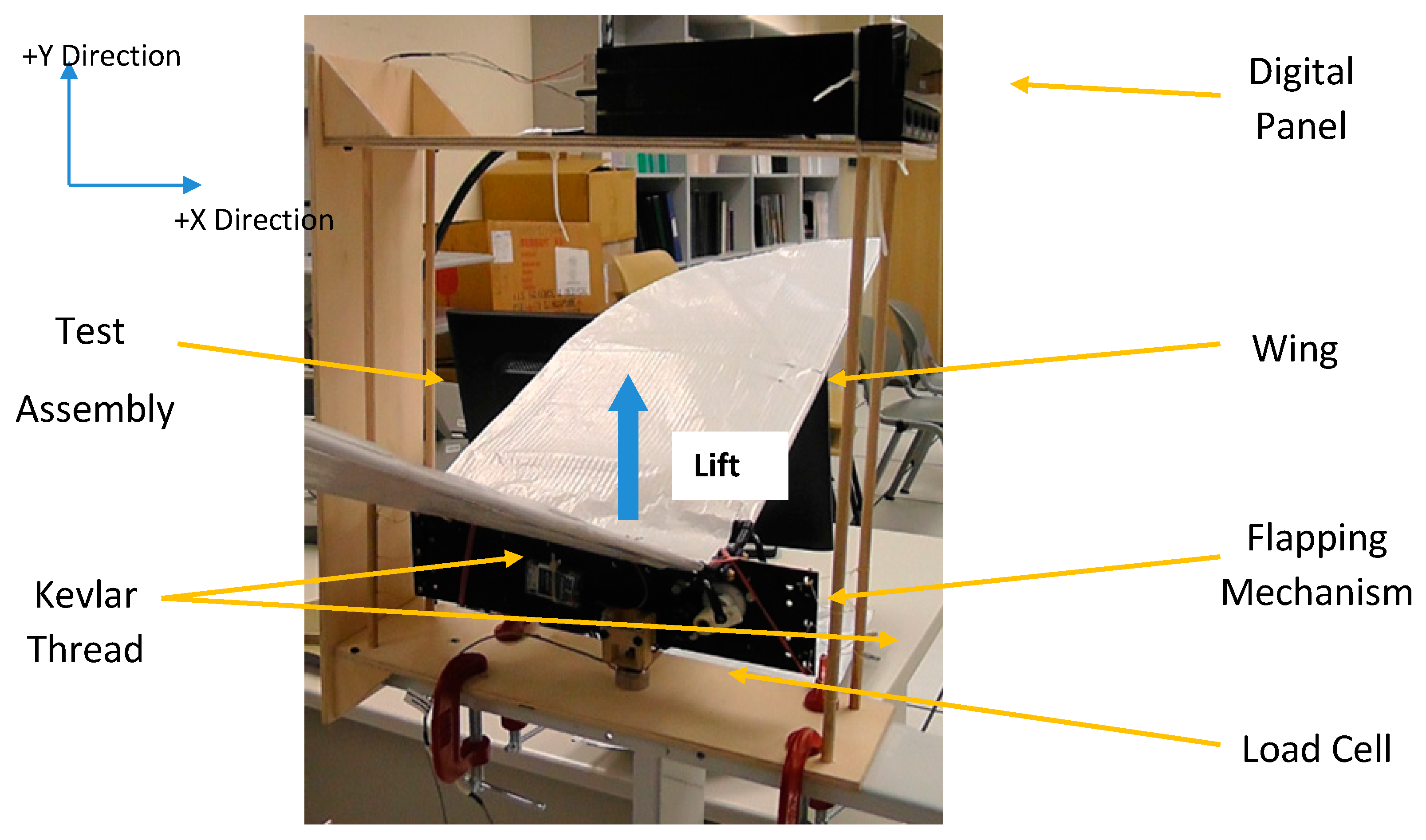
Load Cell Lift Measurement Experiment Setup
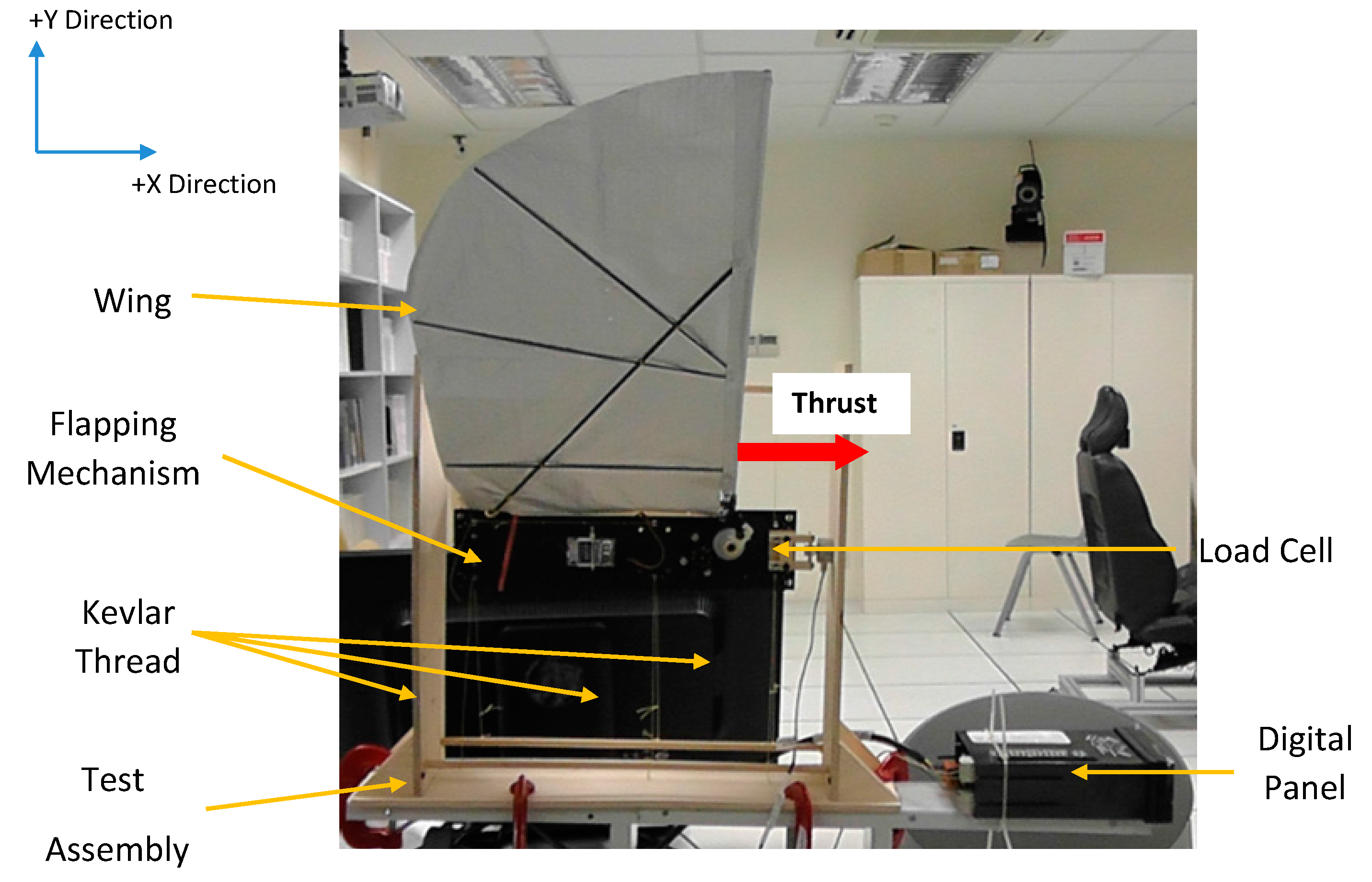
In the lift measurement setup, the test assembly is vertically rotated where the bottom part of the flapping mechanism is attached to the load cell as shown in
Figure 31. The kevlar thread is tied horizontally at the front and back segments of the flapping mechanism, so that it is only capable of motion in the
Y direction which the lift force is measured.
Figure 31.
Load cell lift measurement setup.
Figure 31.
Load cell lift measurement setup.
As the flapping mechanism is moving in the Y direction, the load cell is under both compression and tension, which resulting in negative and positive values respectively displayed on the digital panel. This is due to the matter of fact that a flapping wing is an aerodynamic machine with two strokes, the upstroke and the downstroke. In this experiment, the lift produced for the three different wing designs at three different flapping frequency will be measured and recorded in an Excel spreadsheet. Before recording the lift values during the flapping period, the weight of the flapping mechanism with the wings attached is measured at static condition. By subtracting the weight measured at static condition from all the values obtained during the flapping phase, the true lift force produced by the prototype is then recorded for analysis.
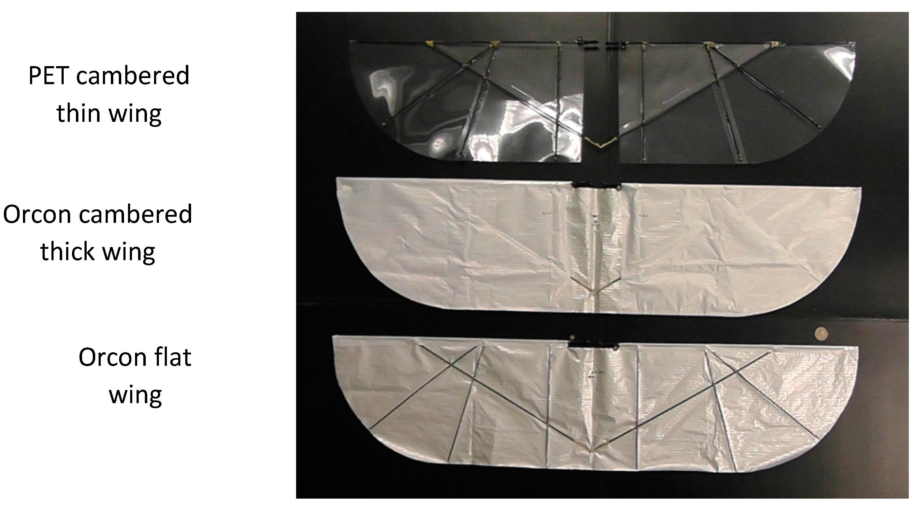
3.4.4. Determination of Flapping Frequency
The flapping frequency of the wings when different amount of power is supplied to the motor is to be determined so as to make a comparison between the three different wing designs, as shown below (
Figure 32), at the various flapping frequency.
Figure 32.
Three different wing designs (bottom view).
Figure 32.
Three different wing designs (bottom view).
The measurement of the flapping frequency of the prototype is achieved through the use of a digital camera. The digital camera is placed in front of the test assembly which allows the author to analyze how the wings are flapped in up- and down-stroke manner. The videos are then loaded into the Ulead software to process the captured video into frames. There are 25 frames for each second of the video recorded. Hence, by calculating the number of frames taken for the prototype to produce a full cycle consisting of upstroke and downstroke as shown in
Figure 33, the period (
T) can be obtained using the following equation:
Once the period is obtained, the flapping frequency (
f) is calculated as follows:
Hence, the flapping frequency can then be determined. The figure below shows the motion of the flapping wings in one full cycle.
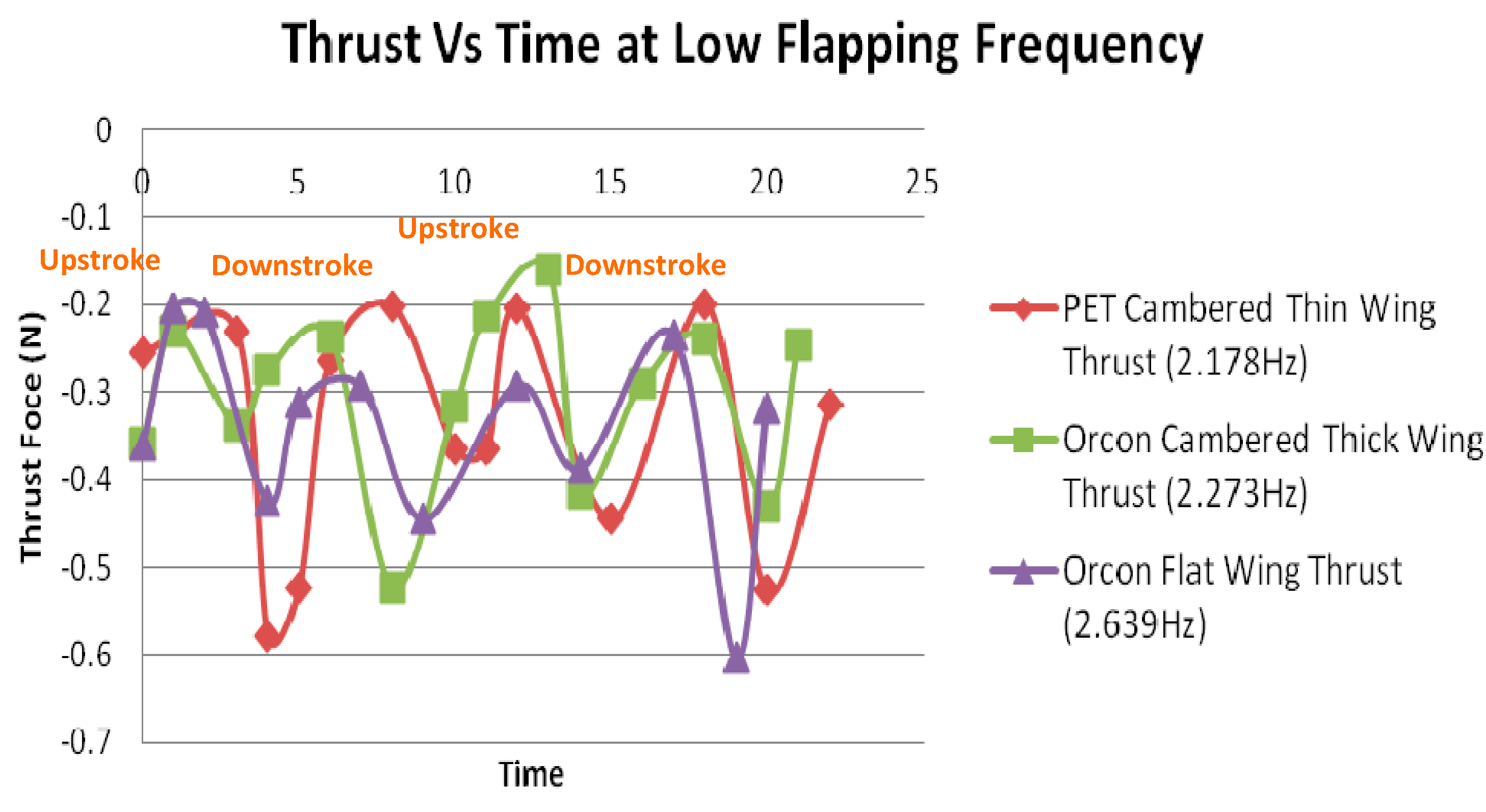
Figure 33.
Thrust against low flapping frequency (2 full cycles).
Figure 33.
Thrust against low flapping frequency (2 full cycles).
3.5. Lift and Thrust Force Results and Analysis
This section presents the findings of various experiments that the authors have conducted. The main element of this section is the results and analysis of evaluation of different wing designs. The average thrust and lift output are measured and compared to different wing designs to understand what styles of wings are more effective. The time-varying force profile can be examined to gain understanding into why particular wing designs prove more effective than others. The results of thrust and lift testing will be analyzed to establish any trends that explain performance differences and this section will be split into five different parts:
Comparison of thrust generation performance between various flapping frequencies at a particular wing design.
Comparison of thrust generation performance between wings of various designs against various flapping frequencies.
Comparison of thrust performance between the load cell measuring setup and swing method.
Comparison of lift generation performance between wings of various designs at different flapping frequencies.
Investigation of lift generation between wings of different designs at various phase angles.
Thrust generation tests are done using the load cell setup method on the three different wing designs. For each wing design, three different flapping frequency staring from low, then medium and lastly to high are evaluated.
It is observed from
Figure 33 that the thrust tends to produce four peaks. This is due to the motion of flapping wings. For each test, thrust performance is recorded in terms of two flapping cycles that consist of upstroke, downstroke, upstroke and downstroke motion, which explains the four peaks that are captured in the graph.
As mentioned in earlier, negative values are obtained when the load cell is under compression. Since the load cell is experiencing compression throughout the flapping period, it means that thrust is always being generated throughout the flapping cycle. More thrust is generated on the downstroke as compared to upstroke.
Apart from that, the slight periodic nature of the thrust is due to the inertial effects of the flapping mechanism. In the graphs above, the inertial effects have not been removed. When flapping with the test set up as described earlier, some inertial effects were present in the thrust direction. This is because the clearances between the flapping mechanism and the test assembly did not purely constrain the flapping in the vertical direction.
3.6. Thrust Comparison between Wings of Various Design
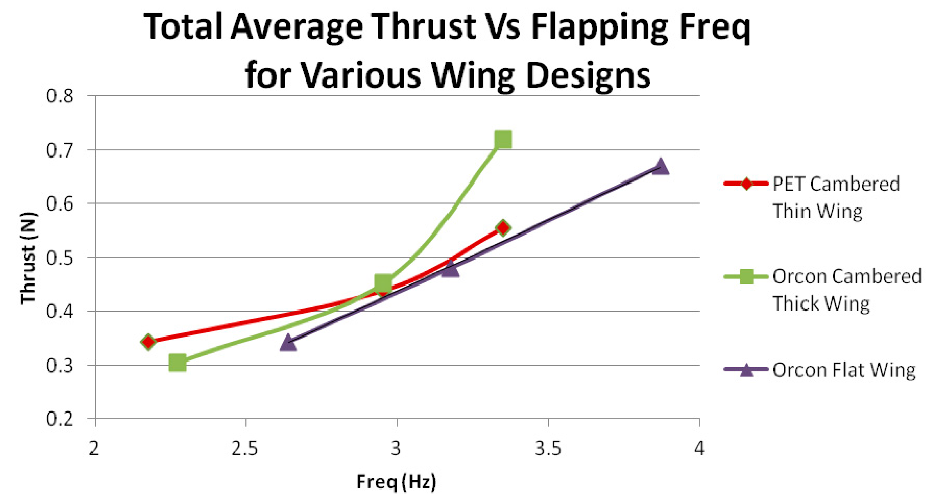
It can be observed from the results as shown in
Figure 34 below that Orcon Flat wing has a better thrust generation performance as compared to the rest of the wing designs. It is interesting to note that the thrust for the Orcon flat wing resulted in a linear relationship when compared against the flapping frequency.
Figure 34.
Total average thrust against flapping frequency for various wings.
Figure 34.
Total average thrust against flapping frequency for various wings.
The flapping wing mechanism constantly appears to produce thrust. The reason for this is that the wing is constantly changing its shape and angle of attack dynamically. On the downstroke the wing is pitched down, forcing air in the −Y direction, while in the upstroke the wing sweeps forward and up, minimizing the movement of air in the direction causing negative thrust. For both cases the thrust is relatively constant throughout the cycle. The magnitude of the thrust appears to slightly increase for the higher frequency.
Orcon Flat wing is much flexible than the other wing designs. Flexible wings can attain efficiency as more elastic the wing is, the more thrust produced and Orcon material is used to achieve a minimum weight. It is observed that PET cambered thin wing has a slightly slower flapping rate. It is because the weight of the flapping mechanism with that pair of wings on is 1.6 N, which weights the highest and tends to have more inertia. Hence, the motor will require more torque to drive the wings. With the same torque, heavier wing will have slightly slower flapping rate which results in a lesser thrust as compared to the Orcon Flat wing.
3.7. Thrust Comparison between Load Cell Setup and Swing Method
Swing angle α is the angle between the initial position and equilibrium position of the prototype ornithopter, and is determined from digital camera images. As discussed, the thrust produced by the ornithopter can be calculated using Equation (5).
Table 2 below shows the comparison of thrust results obtained from the various wing designs at three different flapping frequency.
Table 2.
Comparison of thrust between load cell and swing method.
Table 2.
Comparison of thrust between load cell and swing method.
| Parameter | Flapping Mechanism with |
|---|
| PET Cambered Thin Wing | Orcon Cambered Thick Wing | Orcon Flat Wing |
|---|
| At Low Flapping Frequency |
| Swing Angle (α) | 14° | 12° | 15° |
| Weight (N) | 1.6 | 1.53 | 1.47 |
| Swing Method Thrust T = Wsinα | 0.387 | 0.318 | 0.38 |
| Load Cell Measurement Thrust (N) | 0.343 | 0.305 | 0.344 |
| At Medium Flapping Frequency |
| Swing Angle (α) | 16° | 18° | 20° |
| Weight (N) | 1.6 | 1.53 | 1.47 |
| Swing Method Thrust T = Wsinα | 0.441 | 0.472 | 0.503 |
| Load Cell Measurement | 0.438 | 0.452 | 0.481 |
| Thrust (N) |
| At High Flapping Frequency |
| Swing Angle (α) | 22° | 28° | 28° |
| Weight (N) | 1.6 | 1.53 | 1.47 |
| Swing Method Thrust T = Wsinα | 0.599 | 0.718 | 0.69 |
| Load Cell Measurement Thrust (N) | 0.555 | 0.719 | 0.67 |
Lift generation tests are done using the load cell setup method as mentioned earlier on three different wing designs. Three sets of wings are tested at three different flapping frequency staring from low, then medium and lastly to high, and the lift force is compared at each speed. As the flapping mechanism is moving in the ±Y direction, the load cell is under both compression and tension, which resulting in negative and positive values respectively displayed on the digital panel. This is due to the matter of fact that a flapping wing is an aerodynamic machine with two strokes, the upstroke and the downstroke. During the upstroke, the flapping mechanism will be “pushing” at the load cell, which results in a compression at the load cell and negative lift values will be displayed. During the downstroke, lift is generated and the flapping mechanism will be “pulling” the load cell, which results a tension at the load cell and positive lift values will be shown.
The first wing design to test is the PET cambered thin wing and the plots in
Figure 20 shows the lift against a period of time of 10 full flapping cycle for three different flapping frequency.
It is observed from
Figure 35 that as the flapping frequency goes higher, the lift is slightly increased. The average lift force generated during the low, medium and high flapping cycle are −0.196, −0.14 and −0.218 N respectively.
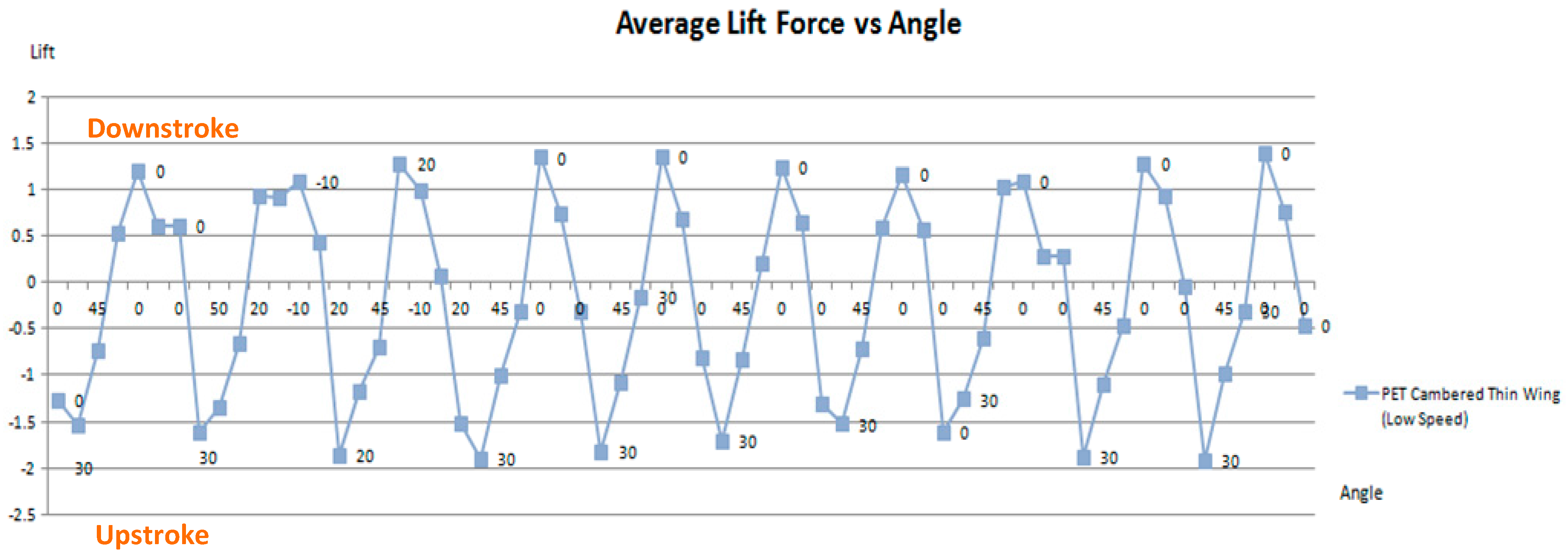
Figure 36 shows the amount of lift force generated at different angles for low flapping frequency.
Figure 35.
PET cambered thin wing lift against time (10 full cycles).
Figure 35.
PET cambered thin wing lift against time (10 full cycles).
Figure 36.
Average lift Force vs. angle (PET cambered thin wing).
Figure 36.
Average lift Force vs. angle (PET cambered thin wing).
From the figure above, the results are consistent with the research made as discussed in earlier section that lift is generated at the down stroke, which reaches the maximum lift of 1.38 N at about 0° to −10° angle. However, the minimum lift of −1.92 N is reached when the flapping wing is on its upstroke. Note that the peak negative lift is greater than the peak positive lift, thus indicating that no net lift is generated.
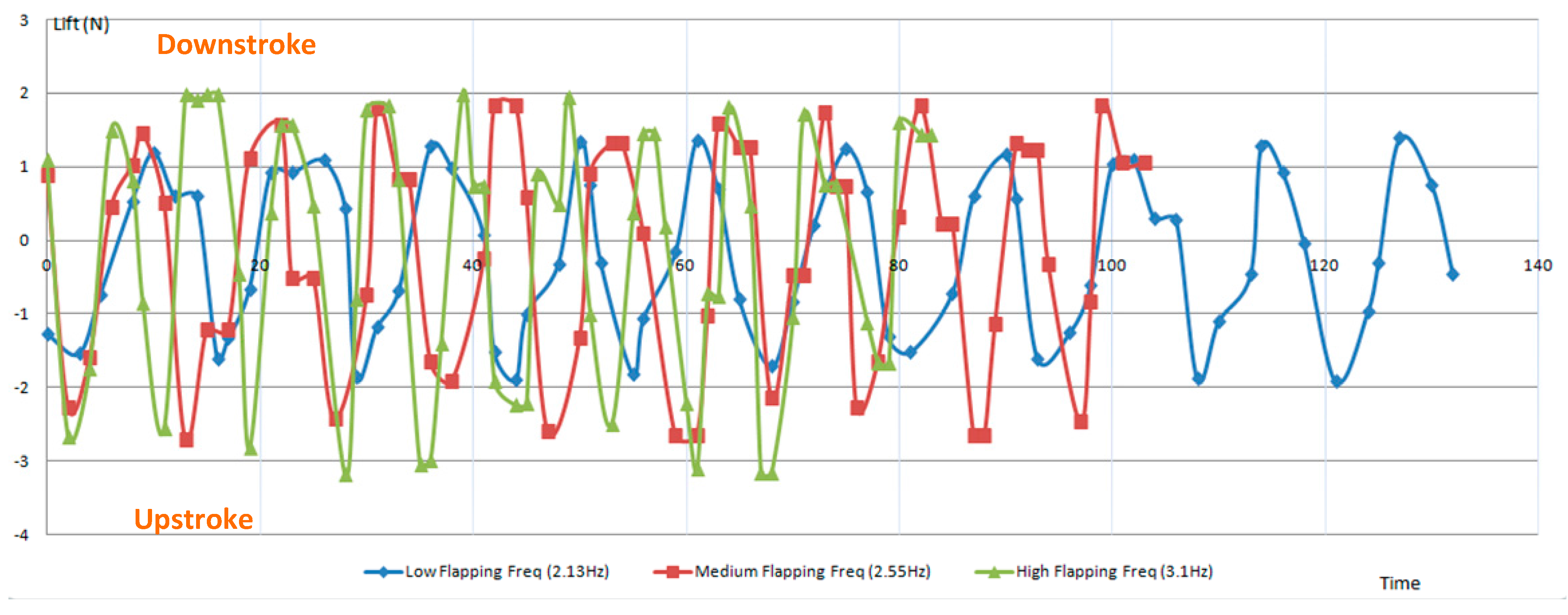
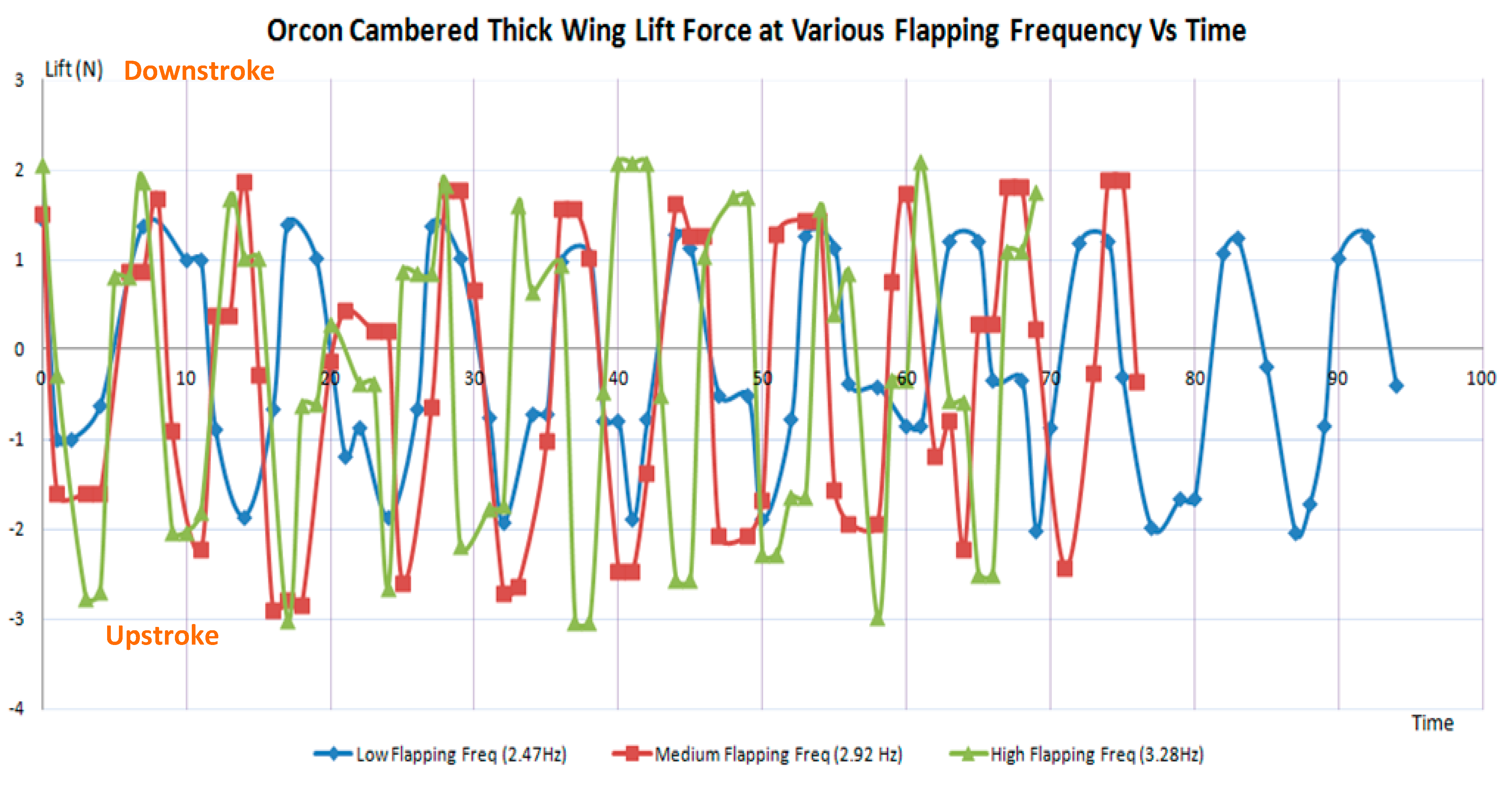
The second wing design to test is the Orcon cambered thick wing and the plots in
Figure 37 shows the lift against a period of time of 10 full flapping cycle for three different flapping frequency.
It is observed from the figure above that the faster the flapping frequency, the higher the lift is generated. The average lift force generated during the low, medium and high flapping cycle are −0.23, −0.26 and −0.3 N, respectively. Therefore, it is also observed that faster the flapping frequency will result a higher negative lift force value.
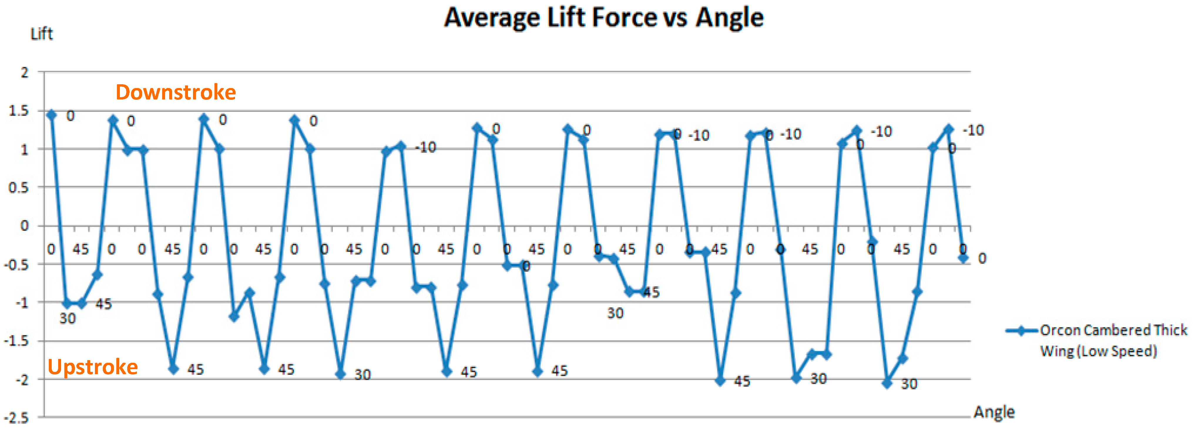
Figure 38 shows the amount of lift force generated at different angles for low flapping frequency.
Figure 37.
Orcon cambered thick wing lift against time (10 full cycles).
Figure 37.
Orcon cambered thick wing lift against time (10 full cycles).
Figure 38.
Average lift force vs. angle (Orcon cambered thick wing).
Figure 38.
Average lift force vs. angle (Orcon cambered thick wing).
From the figure above, the result is similar to the PET cambered thin wing that lift is generated at the down stroke, which reaches the maximum lift of 1.46 N at about 0° to −10° angle. However, the minimum lift of −2.04 N is reached when the flapping wing is on its upstroke. Note that the peak negative lift is greater than the peak positive lift, thus indicating that no net lift is generated.
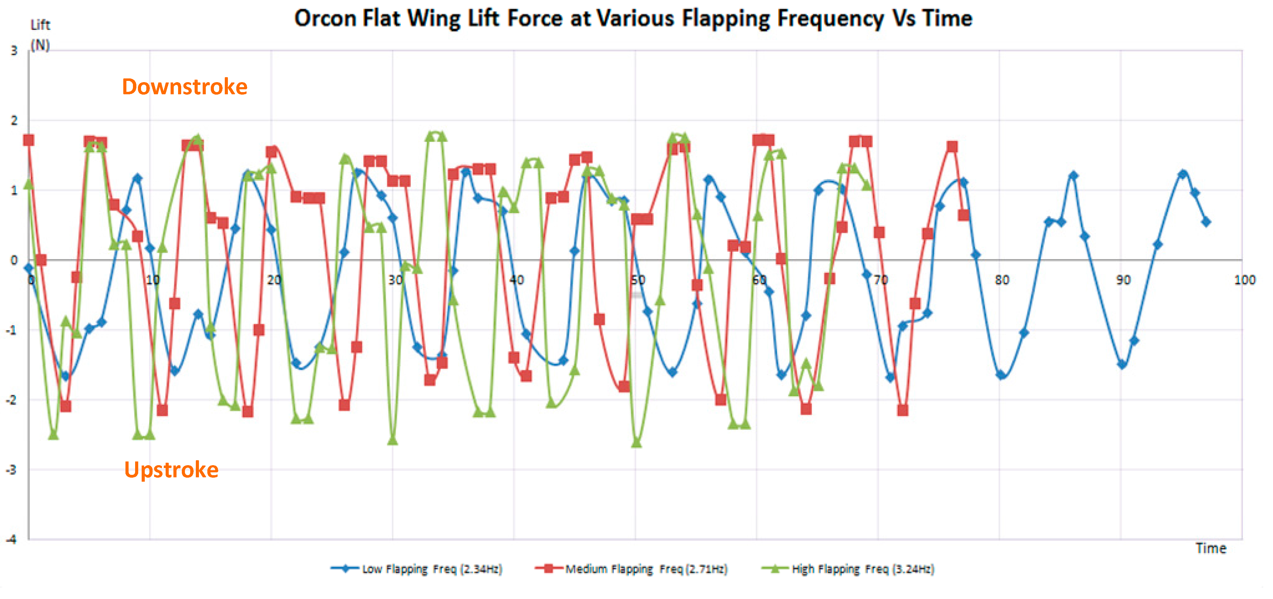
The third wing design to test is the Orcon flat wing and the plots in
Figure 39 shows the lift against a period of time of 10 full flapping cycle for three different flapping frequency. From
Figure 39, it is observed that faster the flapping frequency, the higher the lift is generated. The average lift force generated during the low, medium and high flapping cycle are −0.07, 0.26 and −0.14 N, respectively. It is interesting to find that a small amount of lift is generated at medium flapping frequency.
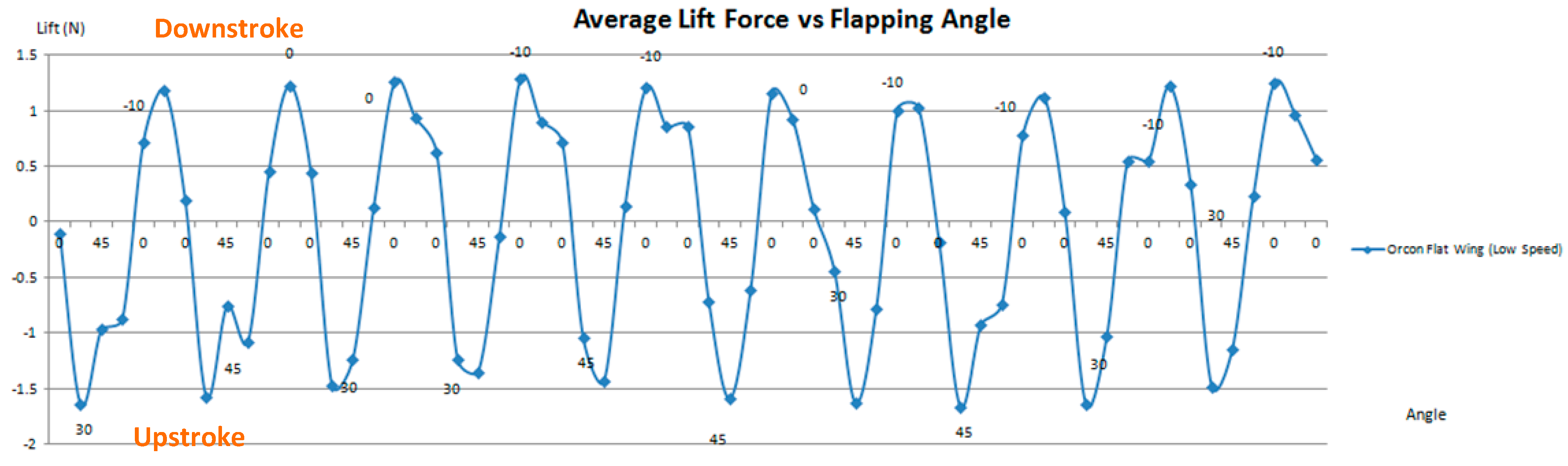
Figure 40 shows the amount of lift force generated at different angles for low flapping frequency.
Figure 39.
Orcon flat wing lift against time (10 full cycles).
Figure 39.
Orcon flat wing lift against time (10 full cycles).
Figure 40.
Average lift force vs. angle (Orcon flat wing).
Figure 40.
Average lift force vs. angle (Orcon flat wing).
From these figures, the result is similar to the previous two tests that lift is generated at the down stroke, which reaches the maximum lift of 1.25 N at about 0° to −10° angle. However, the minimum lift of −1.66 N is reached when the flapping wing is on its upstroke. Note that the peak negative lift is greater than the peak positive lift, thus indicating that no net lift is generated.
3.8. Comparison of Lift between Wings of Various Design
Table 3 shows that the only wing design that produced lift is the Orcon flat wing flapping at medium speed. However, most of the data obtained in this lift test has showed that lift forces produced are generally negative. This means that the prototype ornithopter will not be able to sustain a flight in the air. The Orcon flat wing has shown potential in generating lift with the most lift produced as compared to the rest of the wings. This may be due to the advantage of its light weight and flexibility of wing design. Having a lighter weight will actually allow the flapping mechanism to flap the wings faster. Therefore, improvements and modification are to be made to the wing design in order to produce the sufficient lift to sustain a flight.
Table 3.
Comparison of lift forces.
Table 3.
Comparison of lift forces.
| Type | Low Speed (N) | Medium Speed (N) | High Speed (N) |
|---|
| PET Cambered Thin Wing | −0.196 | −0.140 | −0.218 |
| Orcon Cambered Thick Wing | −0.225 | −0.256 | −0.305 |
| Orcon Flat Wing | −0.075 | 0.264 | −0.142 |
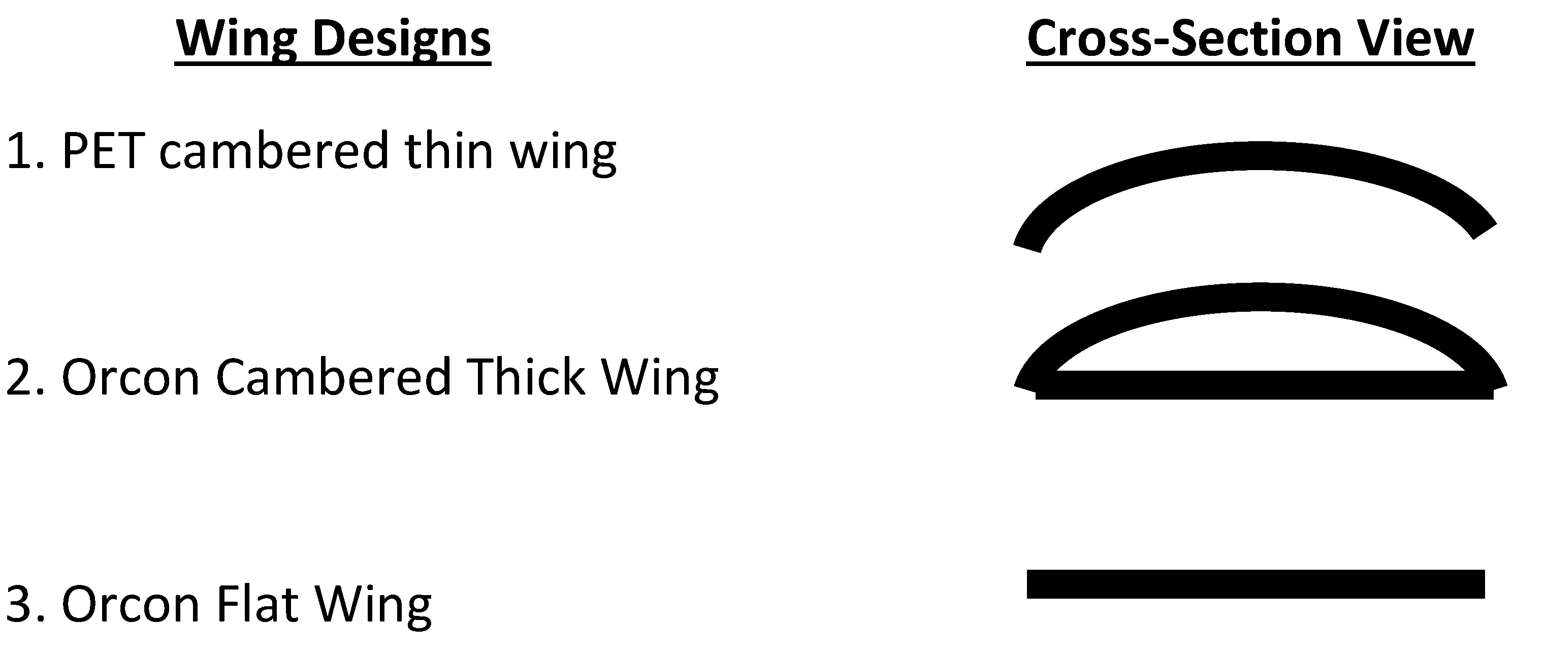
Figure 41 below shows the cross section view of the three various wing designs.
Figure 41.
Cross-section view of the three different wing designs.
Figure 41.
Cross-section view of the three different wing designs.
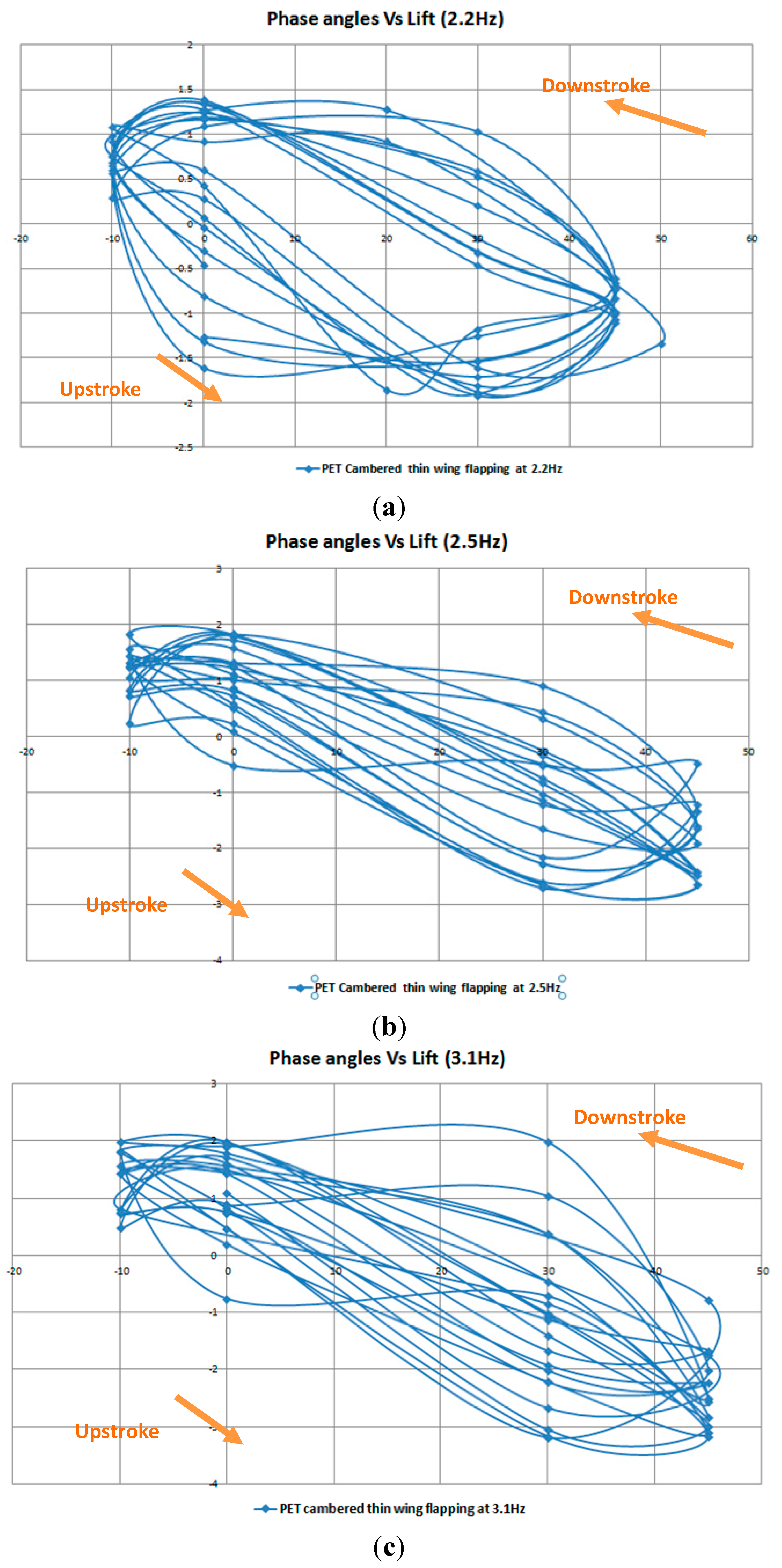
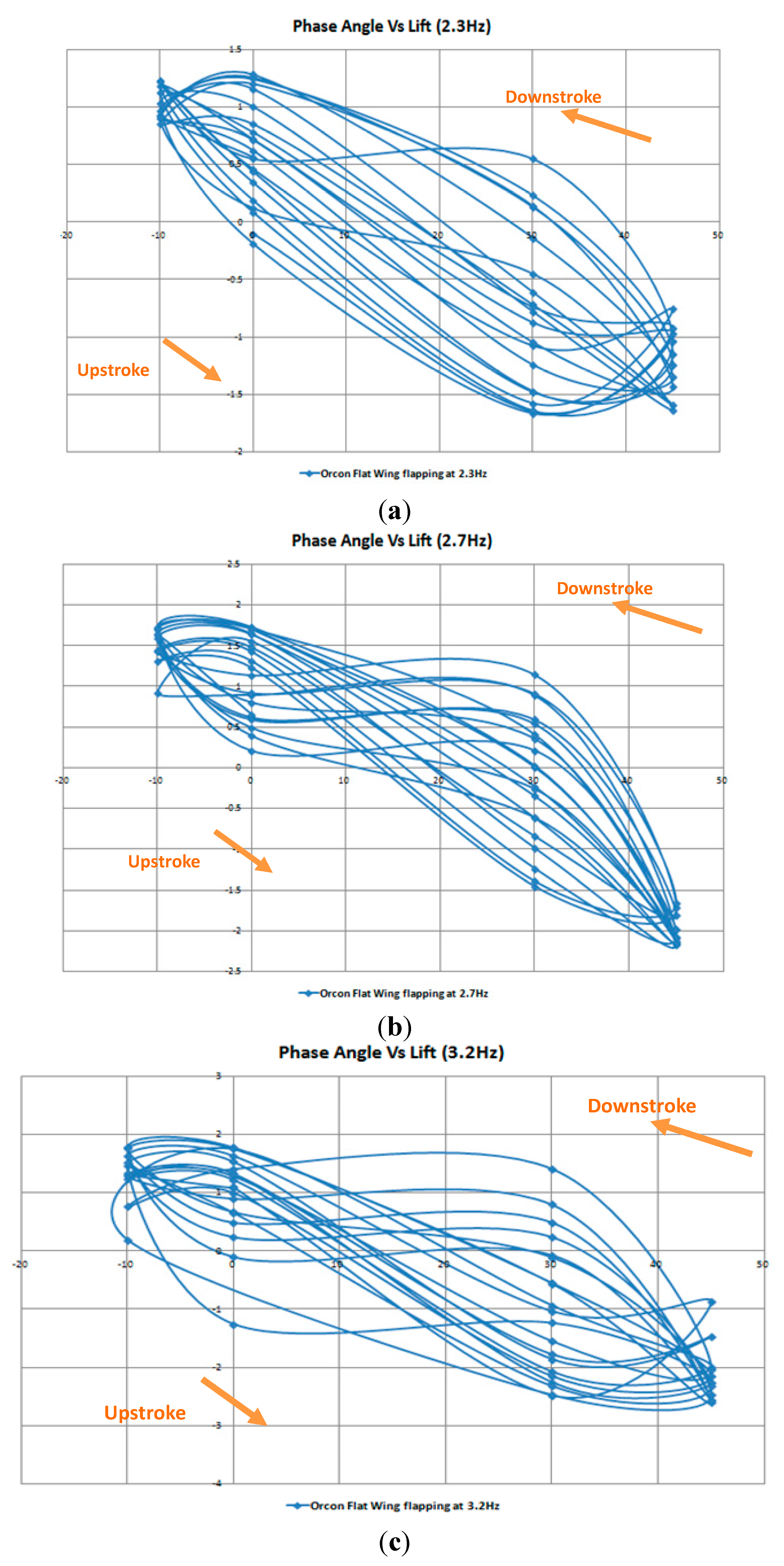
The next few figures (
Figure 42,
Figure 43,
Figure 44,
Figure 45 and
Figure 46) will show the investigation of phase angles against the lift generation for the three different wing designs at various flapping frequency. The first wing design to be discussed is the PET cambered thin wing, followed by the Orcon cambered thick wing and lastly the Orcon flat wing.
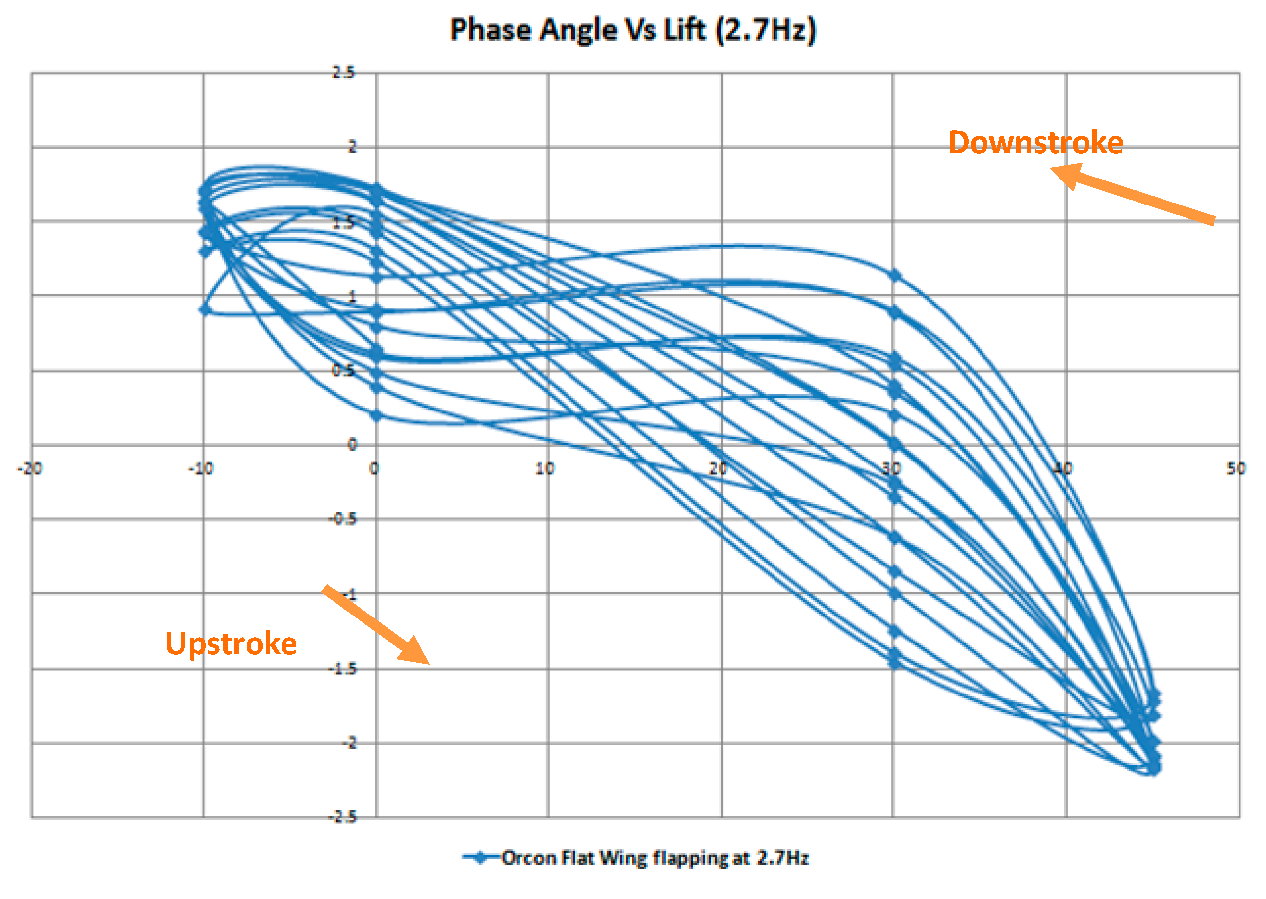
It is observed from the previous figures that as the flapping frequency increases, there is a transition from a “smooth circular” graph to a “figure-of-eight” graph. An example of the lift generation from the Orcon flat wing flapping at the medium frequency graph as shown below, during the initial downstroke, there is a sudden rise in lift until it reaches its peak. When the lift reaches its peak somewhere around 30°, it is noticed that constant lift is produced until it reaches at an angle of 0°. This could be the leading edge vortex (LEV) that causes it. It appears that LEV can enhance lift by attaching the bounded vortex core to the leading edge during wing translation. The vortex, formed roughly parallel to the leading edge of the wing, is trapped by the airflow and remains fixed to the upper surface of the wing. As air flows around the leading edge, it flows over the trapped vortex and is pulled in and down to generate the lift.
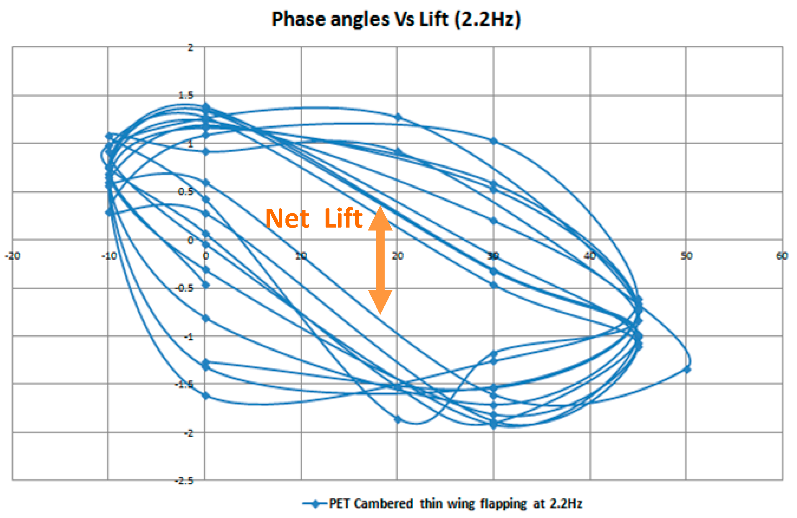
There are two routes that can be seen from the graphs, the first route which is the positive angle transit to negative angle (Downstroke) and the second route is the reverse of the first route (Upstroke). From
Figure 46, the net lift can be easily seen by looking at the difference between the two routes.
Figure 42.
Phase angle vs. lift for PET cambered thin wing. (a) Low speed; (b) medium speed; (c) high speed.
Figure 42.
Phase angle vs. lift for PET cambered thin wing. (a) Low speed; (b) medium speed; (c) high speed.
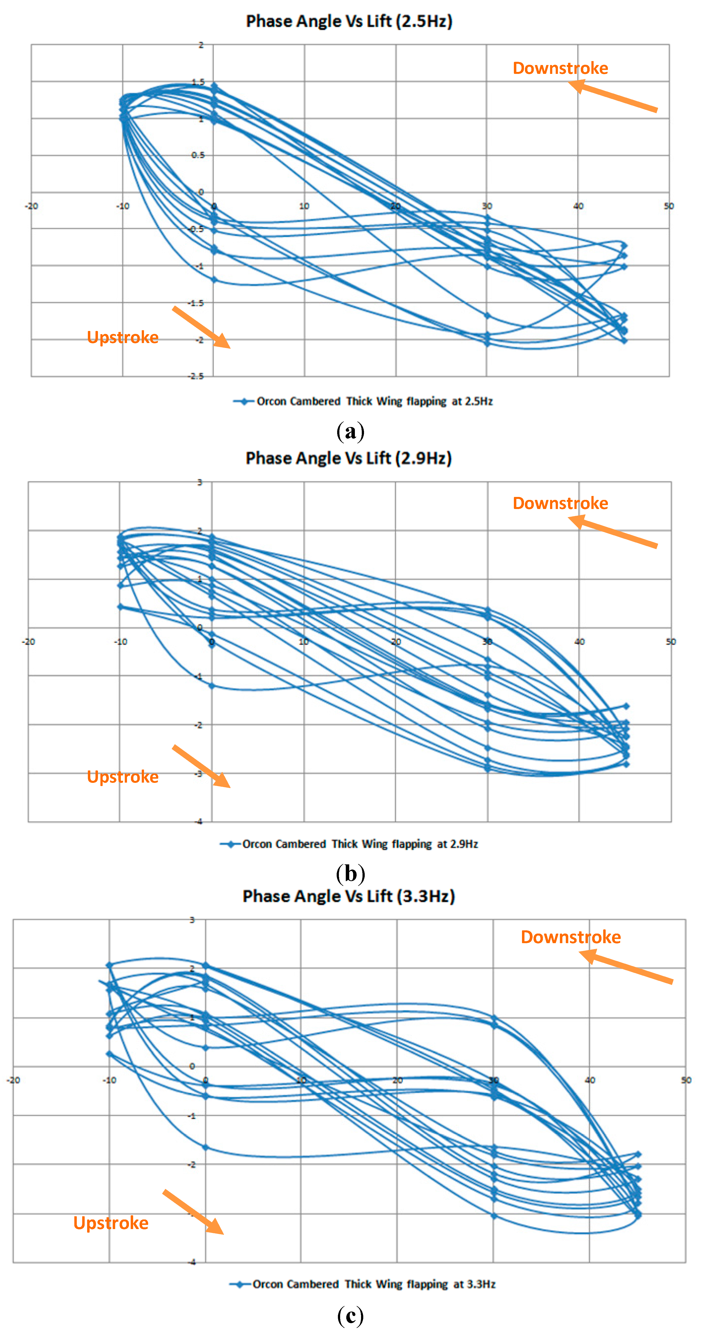
Figure 43.
Phase angle vs. lift for Orcon cambered thick wing. (a) Low speed; (b) medium speed; (c) high speed.
Figure 43.
Phase angle vs. lift for Orcon cambered thick wing. (a) Low speed; (b) medium speed; (c) high speed.
Figure 44.
Phase angle vs. lift for Orcon flat wing. (a) Low speed; (b) medium speed; (c) high speed.
Figure 44.
Phase angle vs. lift for Orcon flat wing. (a) Low speed; (b) medium speed; (c) high speed.
Figure 45.
Phase angle vs. lift for Orcon flat wing flapping at 2.7 Hz.
Figure 45.
Phase angle vs. lift for Orcon flat wing flapping at 2.7 Hz.
Figure 46.
Net lift generation.
Figure 46.
Net lift generation.
5. Conclusions
This paper reports the research and development of our in-house near-resonance type albatross-like flapping wing models for MAV. The flapping wing models mimic the long-distance migratory bird, similar to albatross. CFD results show that the albatross generates lift on its wing mainly by vortex lift mechanism. They do maneuvering by flapping its entire left and right wings at different amplitudes than using (flapping or twisting) its wing tip only. During forward motion, the wings produce a largely tilted leading edge vortex ring. The flight dynamic parameters is estimated, and used as guidance to predict flying characteristics of this type of ornithopter-like flapping wing MAV. With CFD results, we designed, built and flew two near resonance flapping wing MAVs. To test the flapping wing mechanism, a test cell was made to house the prototype and the load cell. When measuring the aerodynamic forces produced in the experiments, it was found that thrust was constantly generated, while lift was periodic in nature following a sinusoidal trend. It was found that lift is predominantly generated on the downstroke, with negative lift being generated on the upstroke. It was found out that the thin wing has both lift and thrust produced on than the PET film and thick cambered wing. Flexible wing generated higher velocities, frequency, lift and thrust. In observing the wing angle motion, it was found out that the lift occurs most when the wing is at 0° and −10°, while negative lift at 30° and 45°.
The design sections of prototypes 2 and 3 have been discussed and evaluated the conceptual designs. There were two fabrication methods that were used, laser cutting and 3D printing. Although it seemed that the 3D printing was a better fabrication method as it allows for more complicated design it does has its limitations in the area of melting point and breaking strength. The third prototype could withstand the high frequency flapping and near resonance amplitude as designed. With remote control, the third prototype was able to take off, climb, cruise and land in flapping mode successfully.


