Abstract
This paper investigates the fly-around formation between the servicer spacecraft and the target spacecraft. Inspired by the spacecraft orbital motion under the Earth’s gravity, an intuitive, analytical guidance law for spatial fly-around formation design with the low-thrust maneuver is proposed. Beginning with the relative translational dynamics based on relative position and velocity, the control input of the guidance law is designed to contain two parts. The first part is the feed-forward term, which makes the relative dynamics a second-order integration model. The second part is the artificial gravity term, which has similar expressions to the Earth’s gravity, and includes the artificial gravitational coefficient and the vector of the artificial gravity center. The above two parameters can be designed to determine the size, shape, and period of the fly-around trajectory. Specifically, three kinds of fly-around trajectories are discussed in detail. The first two are the spatial ellipses with the target spacecraft locating at the focus and the center of the ellipses, respectively. The third is the spatial circle. The proposed method can be easily extended to the design of planar fly-around formation, which is very systematic and comprehensive, and the fuel consumption of the control input is specifically discussed. Numerical simulations are conducted to demonstrate the efficiency of the proposed method.
1. Introduction
Fly-around formation refers to a servicer spacecraft periodically flying around a target spacecraft (or a virtual reference point) within a certain distance. Proximity fly-around formation plays an important role in tasks such as target recognition [1,2], on-orbit service [3], on-orbit assembly [4], and debris removal [5,6]. Depending on whether impulsive or continuous thrust control is applied to the servicer spacecraft, the fly-around formation can be divided into natural fly-around and controlled fly-around. If the target spacecraft is in an ideal circular orbit, the analytical solution of the linearized Clohessy–Wiltshire (CW) equation shows that when the initial relative states of the two spacecraft meet certain constraints, a natural fly-around formation is achieved, and the period of the formation is equal to the orbital period of the target spacecraft. The shape of the fly-around trajectory in the orbital plane is an ellipse with a 2:1 axis ratio. Furthermore, it is a simple harmonic motion in the direction perpendicular to the orbital plane [7].
The realization of the controlled fly-around depends mainly on the active control acting on the servicer spacecraft. Its main feature is that the size, shape, and period of the fly-around formation can be controlled. The CanX-4 and CanX-5 nanosatellites launched in 2014 carried out projected circular fly-around formations with relative distances of 100 m and 50 m, respectively [8]. If the fly-around period is less than the orbital period of the target spacecraft, it is called fast fly-around, and otherwise, slow fly-around. The fast fly-around has great requirements for application in on-orbit missions. If the target spacecraft encounters an emergency, such as sudden failure, space debris impact, or its working state needing to be estimated from the outside in a short time, the fast fly-around can be used to quickly observe the target and obtain the necessary information. Similarly, slow fly-around also has great application requirements. A stable relative configuration of the target spacecraft or detailed observations of its global characteristics can be achieved through slow fly-around. The choice of fast or slow fly-around is mainly based on the mission requirements, but it is also necessary to consider the fuel consumption of the servicer spacecraft.
Currently, the most researched is the use of the multi-impulse maneuver to achieve controlled fly-around. Ivanov, D. et al. [9] reviewed control methods for nanosatellite formation flying, covering both impulsive maneuvers and continuous thrust control strategies, and analyzed the applicability of multi-impulse maneuvers in close-proximity operations. Joffre, E. et al. [10] designed a heliocentric orbital formation configuration for the LISA mission and discussed schemes for using multi-impulse maneuvers to maintain high-precision relative orbits between satellites. Liu, L. et al. [11] studied the formation control of solar sail spacecraft near planetary orbits and proposed an event-triggered impulsive cooperative control method suitable for periodic fly-around missions. Shuailong Zhao et al. [12] validated a multi-impulse control algorithm for autonomous formation flying in the PRISMA mission. Zhang et al. [13] used relative orbit elements to design the bi-elliptical and bi-teardrop formations, and the fly-around distance and relative view angle were specifically discussed. Shengzhou Bai et al. [14] proposed an impulse control algorithm for establishing parallelogram formation flying, successfully achieving single-loop and multi-loop formation flight configurations.
In terms of continuous-thrust-controlled fly-around, Zhao et al. [15] derived a nonlinear dynamical model for spacecraft formation systems based on the circular restricted three-body problem (CR3BP) and proposed a hybrid continuous low-thrust propulsion scheme combining solar sail and Coulomb force propulsion. Scharnagl et al. [16] analyzed satellite motion characteristics under continuous low-thrust conditions using Hamilton functions, establishing optimal transfer mathematical models for velocity–inclination and velocity–RAAN (Right Ascension of the Ascending Node) relationships, thereby providing continuous maneuver strategies for small satellites. To address long-term formation maintenance, Lin Zhao et al. [17] developed a continuous low-thrust control strategy for loose displacement formations by transforming optimal control problems into nonlinear programming frameworks. De La Rue, W. [18] compared electric, chemical, and cold gas propulsion systems for formation flight and end-of-mission deorbiting, demonstrating the advantages of resistojet thrusters in low-altitude orbits. Additionally, Shengzhou Bai et al. [19] proposed analytical natural circumnavigation formations for dual-spacecraft systems, enabling periodic revisits to designated points and their vicinity. In recent years, micro–nano satellites have been widely used in space missions [20,21], such as deep space exploration [22,23,24], technology demonstration [25], etc. In these tasks, continuous low-thrust technologies such as cold gas propulsion and electric propulsion, which can produce thrust ranges from μN to N levels, have played important roles. Electric propulsion systems, on the other hand, can achieve great improvement in specific impulses (Isp) over chemical propulsion, and will play a greater role in the future. Thus, this article focuses on the design of fly-around formation based on the low-thrust maneuver.
The purpose of this paper is to develop an intuitive, analytical, and systematic guidance law for fly-around formation design based on low-thrust control. Throughout this study, the relative motion dynamics are modeled under the classical two-body problem assumption. The outline of this paper is as follows. In Section 2, the coordinate systems, relative dynamics, and analytical guidance law are introduced. In Section 3, three kinds of fly-around trajectories are discussed in detail, including spatial ellipses and circles, and numerical simulations are conducted to evaluate the influence of design parameters on the size, shape, and period on the fly-around trajectory. The extension to the design of planar fly-around formation and fuel consumption is also analyzed. Conclusions are drawn in Section 4.
2. Analytical Guidance Law Design
2.1. Relative Dynamics
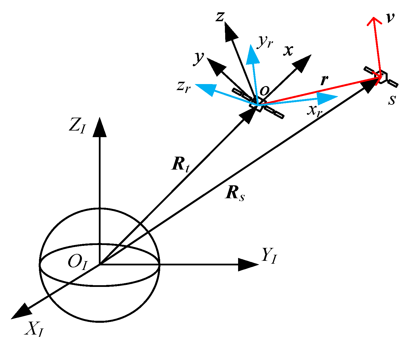
Earth-Centered Inertial (ECI) Coordinate System. The origin of the ECI coordinate system is centered on Earth, the ZI-axis is along the rotational axis, and the XI-axis points toward the vernal equinox. The YI-axis completes the right-handed orthogonal [26].
Local Vertical–Local Horizontal (LVLH) Coordinate System. The origin of the LVLH coordinate system lies on the center of mass (c.m.) of the target spacecraft. The x-axis is in the opposite direction to Earth’s center, the y-axis is along the direction of flight, and the z-axis completes the right-handed orthogonal. The orbital plane of the target is defined as plane [27].
Relative Vertical–Relative Horizontal (RVRH) Coordinate System. The origin of the RVRH coordinate system also lies on the c.m. of the target spacecraft. Assuming that the relative position vector r and the relative velocity vector v from the servicer to the target are non-collinear, the above two vectors determine the plane , and the norm vector of plane is n, described as . The zr-axis is along the direction of norm vector n, the yr-axis is along the direction of relative velocity vector v, and the xr-axis completes the right-handed orthogonal. Obviously, since the servicer is constantly moving relative to the target, the RVRH coordinate system is time-varying. Define the time when the continuous low thrust is initially applied to the servicer as the initial time, and the RVRH coordinate system of the initial time is uniquely determined.
The relative geometrical relationship and coordinate systems are illustrated in Figure 1.
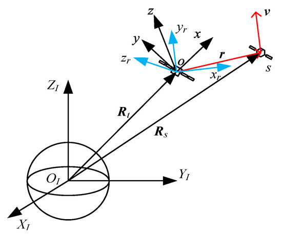
Figure 1.
Geometrical relationship and coordinate systems.
As shown in Figure 1, and denote vectors directed from the Earth center to the c.m. of the target and the servicer, respectively. The relative position can be represented as . Assuming that the target has no active control and the orbit perturbations are ignored, the relative translational dynamics in the ECI coordinate system can be obtained as follows:
where is the geocentric gravitational coefficient, is the active control input of the servicer, and the first term at the right of Equation (1) is the differential spherical Earth gravity. Ignoring the second-order small satellite of the differential spherical Earth gravity, the relative translational dynamics in the LVLH coordinate system can be obtained as follows:
where and are the unit vectors of and , respectively, and are the target’s orbital angular velocity and angular acceleration, respectively. Equation (2) can describe not only the relative motion of a circular reference orbit, but also an elliptical reference orbit. This linearized model is applicable for short distances. Additionally, since the J2 perturbation and differential drag effects are not incorporated, the model is valid for a limited time frame.
2.2. Guidance Law Design
Under the action of dynamic Equation (2), the trajectory of the servicer relative to the target is defined as the nominal trajectory. The principle of low-thrust fly-around formation design is to make the nominal trajectory form the desired configuration through the control input [28].
Based on the principle of spacecraft orbital motion under geocentric gravity, the trajectory of the spacecraft relative to the center of Earth is a conic curve, and when the apparent energy of the spacecraft is less than zero, the trajectory is a closed conic curve, such as an ellipse or a circle [29]. The control input of the guidance law is designed to contain two parts. The first part is the feedforward term, which makes the relative dynamics a second-order integration model and can be represented as follows:
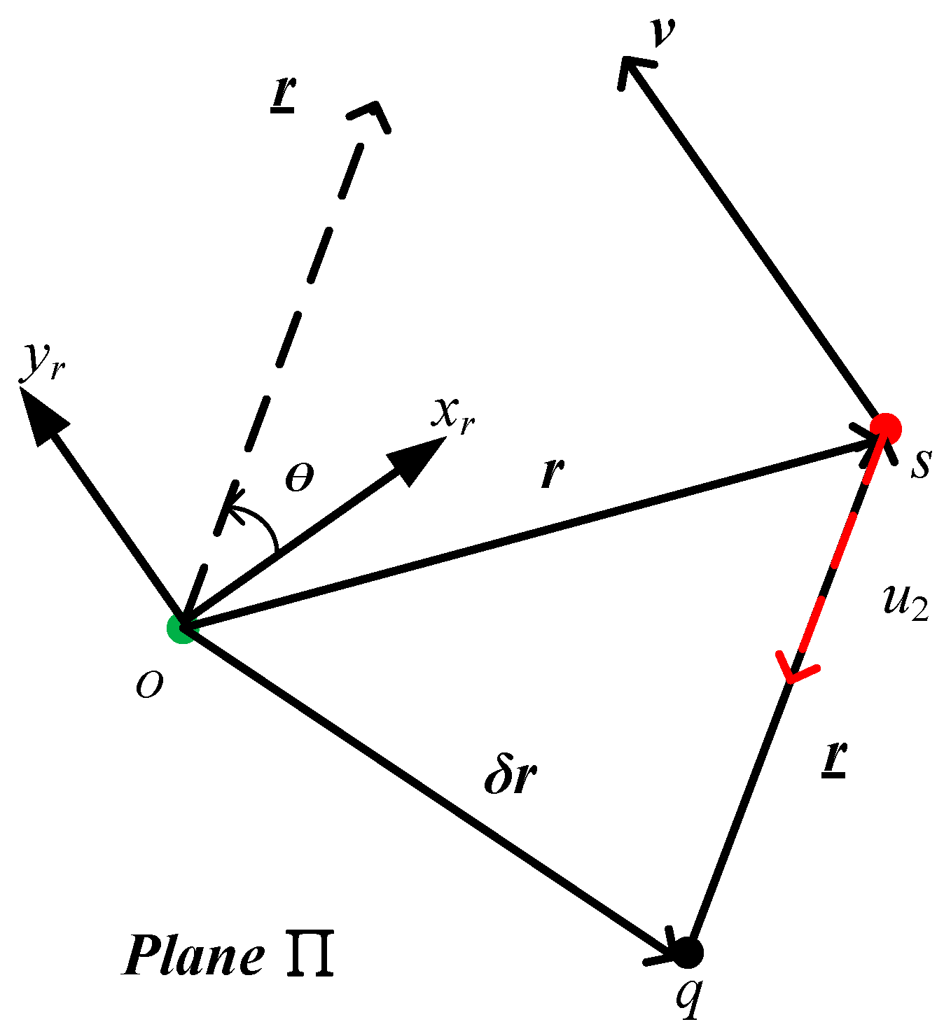
The second part is the artificial gravity term, which has similar expressions to geocentric gravity. The center point of artificial gravity q is a fixed point relative to the LVLH coordinate system, and lies in the plane . It is defined as the relative position from the point q to the target, and expression holds. Then, expressions and can be derived in the LVLH coordinate system. The artificial gravity can be represented as follows:
where is the artificial gravitational coefficient.
The artificial gravity and relationship among the above vectors are illustrated in Figure 2.
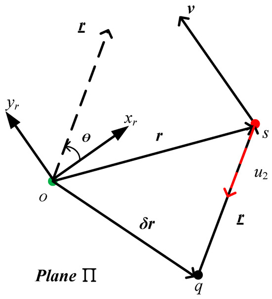
Figure 2.
Artificial gravity and vector relationship.
Where angle is the angle from the xr-axis to the vector .
By defining the control input as and combining with Equations (3) and (4), the control input can be represented as follows:
According to Equation (2), the dynamic equation to obtain the desired nominal trajectory is as follows:
According to Equation (6), the fly-around trajectory is a conic curve with point q as the focus, and lies in the plane determined by the relative position and relative velocity . The type and shape of the fly-around trajectory are not only affected by the relative position and relative velocity at the initial time of the control action, but also by the parameters to be designed, such as the artificial gravitational coefficient and the vector of artificial gravity center or .
Under the control input shown in Equation (5), the apparent energy of the servicer relative to the target is defined as follows:
In order to make the relative fly-around trajectory a closed conic curve, when the artificial gravitational coefficient is designed, the apparent energy needs to be less than zero, so that the artificial gravitational coefficient meets the following constraint:
2.3. Fly-Around Formation Analysis
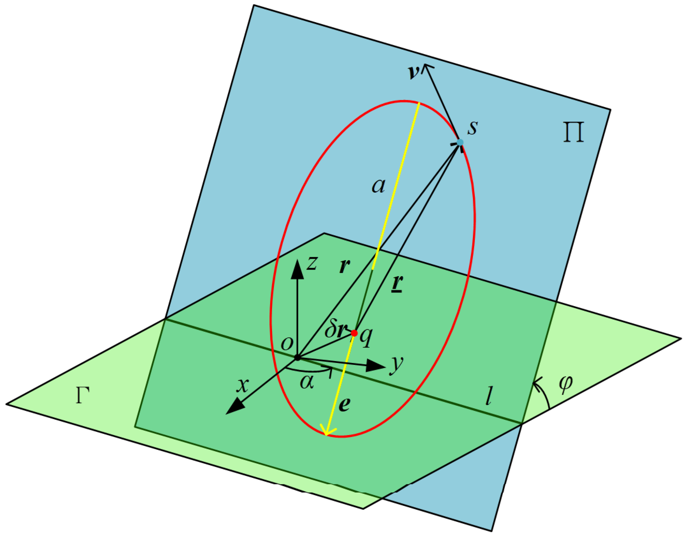
According to the designed guidance law in Section 2.2, the spatial configuration of the obtained fly-around formation is illustrated in Figure 3.
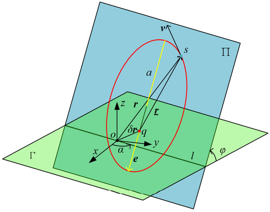
Figure 3.
Spatial configuration of the fly-around formation.
Where line l is the intersection of the plane and the plane , and l passes through point o. is defined as the angle from x-axis to the line l, similar to the concept of ascending node right ascension in absolute orbital elements. Furthermore, is the angle between the plane and , similar to the concept of orbital inclination. According to and , the spatial position of the formation can be determined.
is defined as the moment of momentum of the fly-around trajectory. In the LVLH coordinate system, it can be expressed as follows:
where
Then, the size and shape of the fly-around trajectory are analyzed. The semi-major axis of the fly-around trajectory can be obtained from Equations (6) and (7).
Furthermore, the fly-around period T can be obtained as follows:
It can be seen from Equations (11) and (12) that under the condition that and the initial relative states have been determined, the design of can be used to control the semi-major axis and the period of the fly-around trajectory.
In order to evaluate the relationship between the artificial gravitational coefficient and the fly-around period, the variable and function are defined.
The derivation of the function with respect to can be obtained.
It can be seen that when expression is satisfied, that is , the function takes the extreme value. When expression is obtained, the function decreases. According to the relationship between variable and the artificial gravitational coefficient , as increases, the fly-around period T decreases at the same time. Therefore, increasing the artificial gravitational coefficient can increase the fly-around speed and reduce the fly-around period.
By referring to the calculation expression of eccentricity in the two-body problem [30], according to the initial relative states and the designed artificial gravitational coefficient, the eccentricity of the fly-around trajectory can be obtained.
Defining the following variables such as , , , and , Equation (15) can be expressed as follows:
The curve described using Equation (16) is a parabola with an upward opening. When expression is met, the formula holds, and the eccentricity of the fly-around trajectory takes the minimum value.
By analyzing Equation (17), when condition is satisfied, the formula is established, and the fly-around trajectory is a spatial circle centered on point q. When the minimum eccentricity requirement is met, the corresponding fly-around period is as follows:
It can be concluded that when the artificial gravitational coefficient satisfies the constraint , with the increase of , the eccentricity and period of the fly-around trajectory decreases. When constraint is satisfied, with the increase of , the eccentricity increases, and the period also decreases.
3. Typical Fly-Around Configuration
3.1. Spatial Ellipse with Target Spacecraft as the Focus
According to Equation (6), if the focus of the fly-around ellipse is located at the position of the target, then formulas and are established. When the initial relative states are known, the fly-around period and the shape of the ellipse depend on the design of the artificial gravitational coefficient, which is determined by Equations (11), (12), and (15), respectively.
A simulation example is conducted to verify the feasibility of the above-mentioned guidance law. The target is in elliptical orbit, which is a Molniya orbit, and the servicer is near the target. The relevant orbit parameters are shown in Table 1.

Table 1.
Orbit parameters of the target spacecraft.
The relative position and relative velocity from servicer to target in the LVLH coordinate systems are and , respectively. According to Equations (9) and (10), the angles that characterize the spatial position of the fly-around trajectory relative to the orbital plane of the target can be obtained. Then, the relative states obtained via rotation transformation are described in the RVRH coordinate systems as and , respectively.
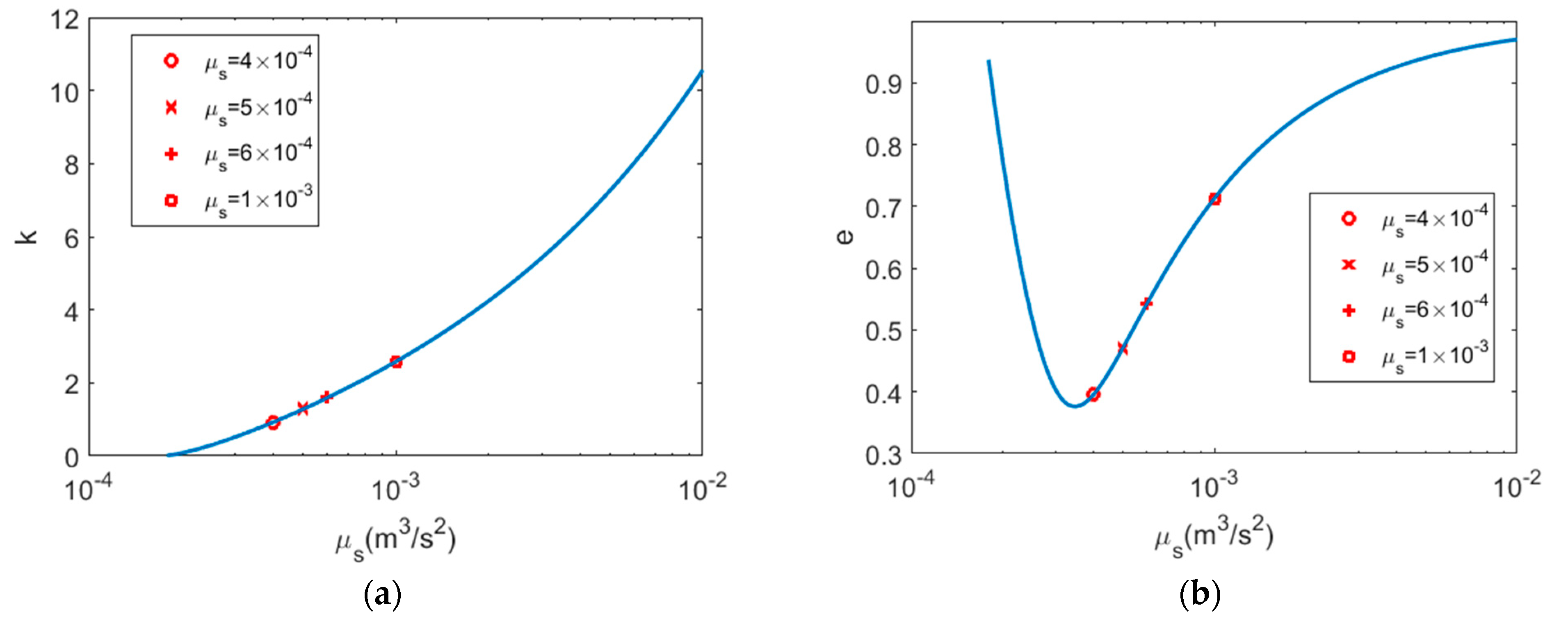
Firstly, the influence of the artificial gravitational coefficient on the fly-around speed and eccentricity are analyzed through simulation. Parameter k is defined as the ratio of the average angular velocity of the fly-around trajectory relative to the average angular velocity reference orbit .
The size of k determines the speed of the trajectory, and the sign of k determines whether the direction of the trajectory is clockwise or counterclockwise.
The simulation results are illustrated in Figure 4.
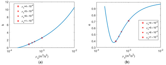
Figure 4.
Influence of artificial gravitational coefficient on fly-around speed (a) and eccentricity (b).
The simulation results verify the above analysis results, that is, as the artificial gravitational coefficient increases, the fly-around speed continues to increase, and at the same time, there is a trajectory with the minimum eccentricity.
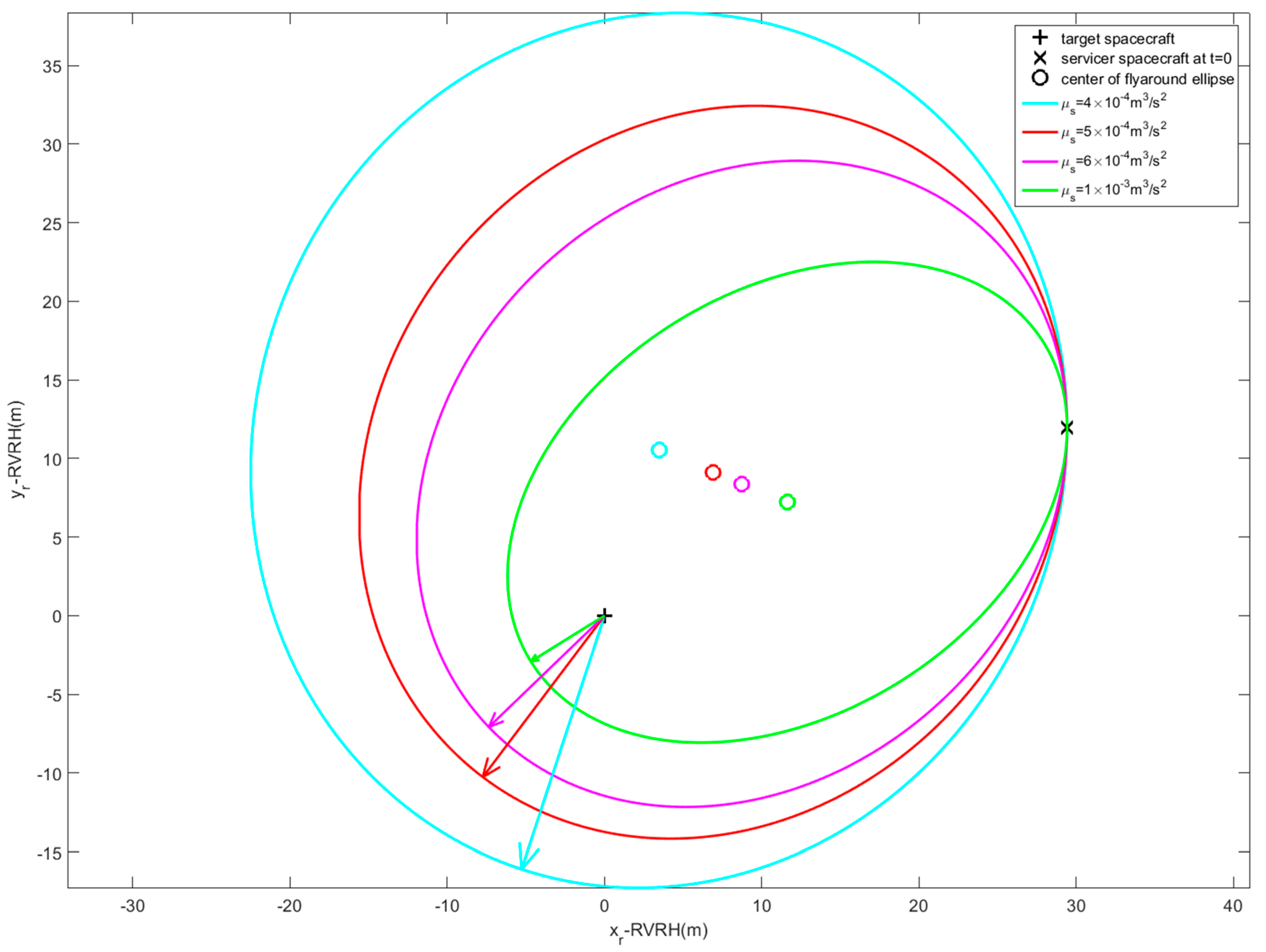
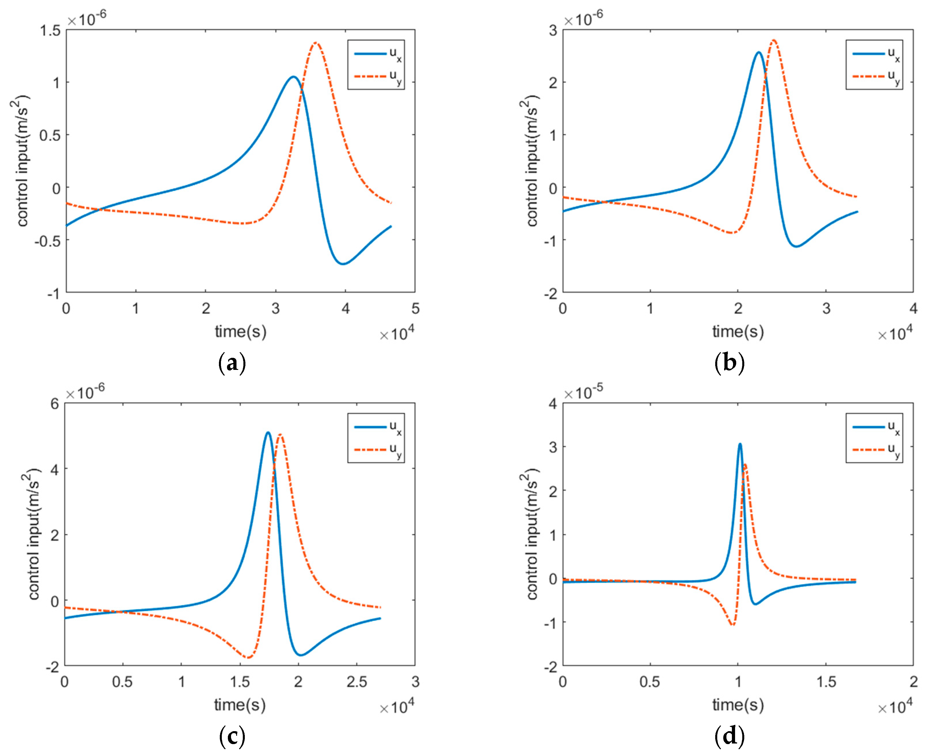
The shape of the fly-around trajectory corresponding to different artificial gravitational coefficients is simulated and analyzed, and Figure 5 presents the simulation results for δr = 0. Figure 6 shows the control inputs as a function of time.
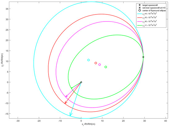
Figure 5.
Fly-around ellipses with typical artificial gravitational coefficients.
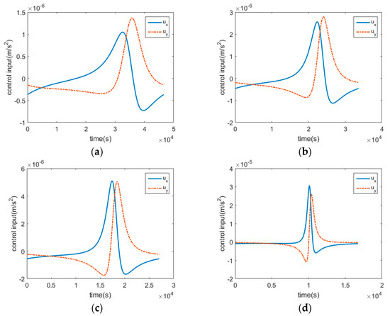
Figure 6.
Control inputs with typical artificial gravitational coefficients are 4 × 10⁻⁴ m3/s2 (a), 5 × 10⁻⁴ m3/s2 (b), 6 × 10⁻⁴ m3/s2 (c), and 1 × 10⁻³ m3/s2 (d), respectively.
In Figure 5, the arrowed line segment points from the focus of the ellipse to the periapsis. The simulation results show that even if different artificial gravitational coefficients are designed, different elliptical trajectories with a target as the focus can still be obtained, which verifies the effectiveness of the designed guidance law. For any initial relative position and relative velocity, a series of fly-around trajectories can be achieved through the guidance law. When the artificial gravitational coefficient is different, the center of the elliptical trajectory, as well as the shape and size, are also different. Through the adjustment of the initial relative states, combined with the design of the artificial gravitational coefficient, the desired configuration can be achieved.
3.2. Spatial Ellipse with Target Spacecraft as the Center
In order for the target spacecraft to be located at the center of the elliptical trajectory, the formula needs to be satisfied, namely the following:
Define vectors and described in the RVRH coordinate system as and , respectively. The angle is the angle from the xr-axis to the vector , and then, the coordinate component of Equation (20) is expressed as follows:
Equation (21) is a nonlinear equation, and the parameters , , and are the parameters for designing the fly-around trajectory. When and are known, the above three parameters cannot be uniquely determined. Specifically, define () and obtain the following expression:
Simplify the above Equation to obtain the following:
According to Equation (23), if holds and the position of the servicer relative to the target is determined, and can be determined, and then and can be determined according to Equation (22). Note that and are not uniquely certain, there are multiple elliptical trajectories centered on the target spacecraft at the same time.
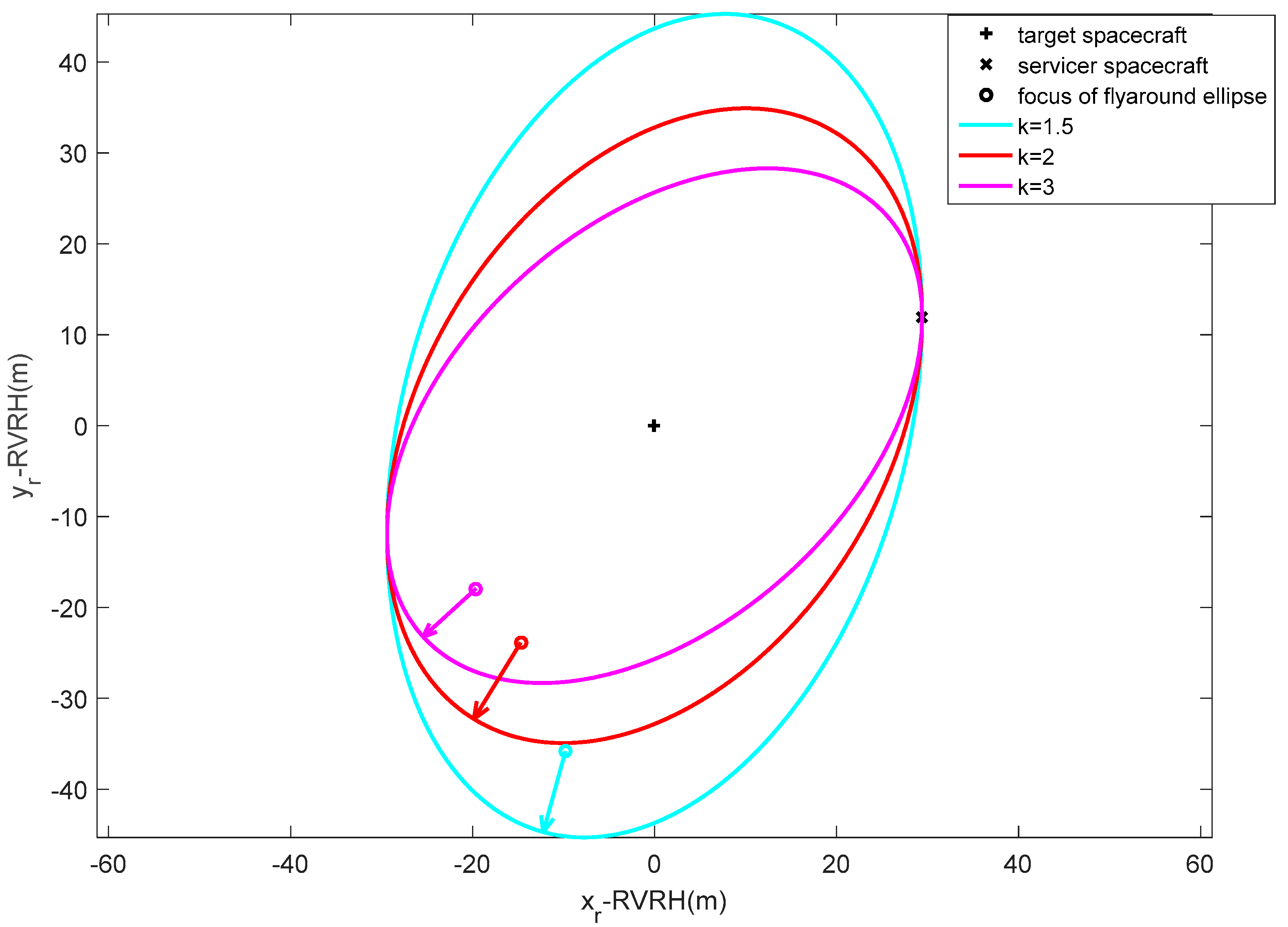
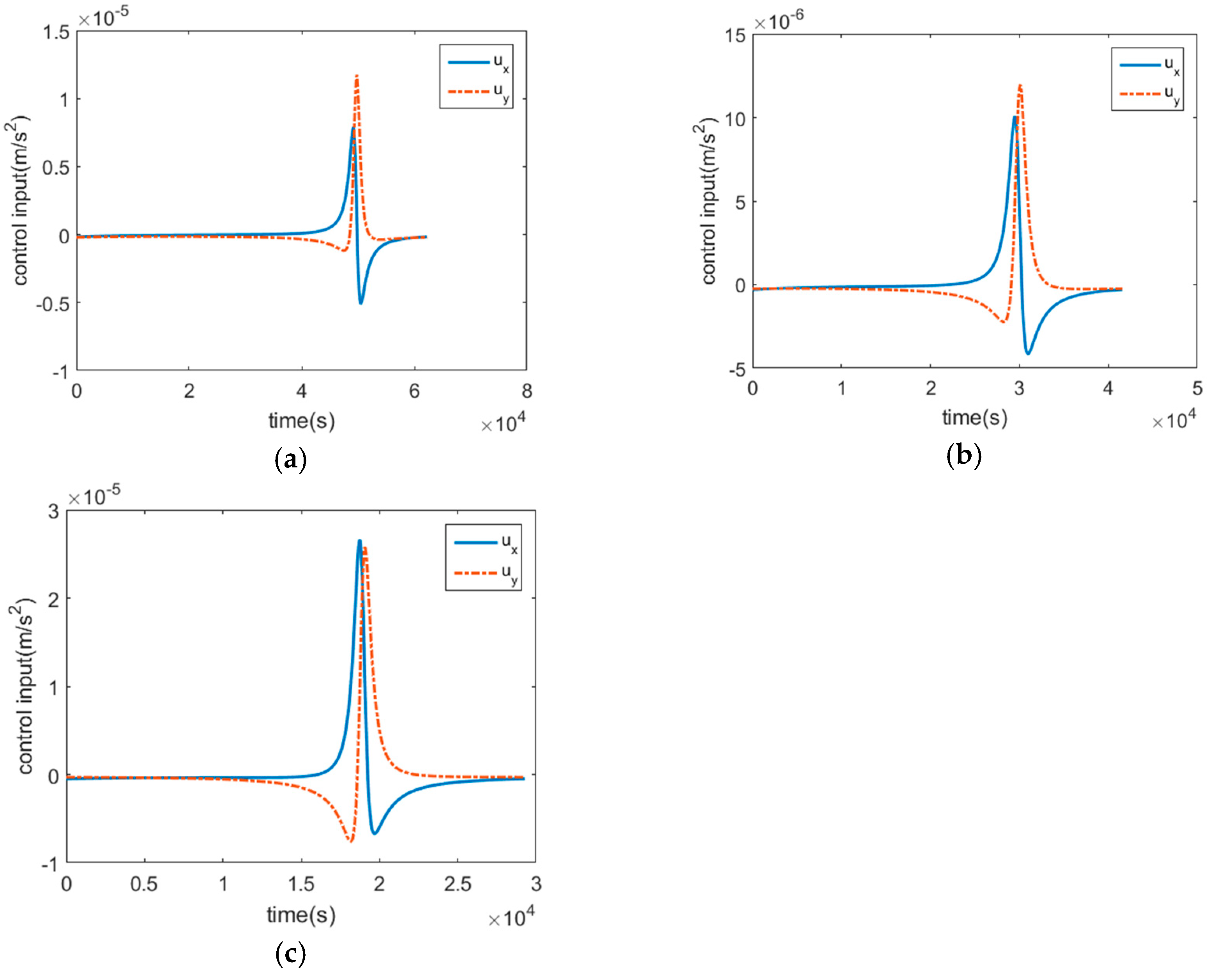
The trajectories corresponding to different design parameters are simulated and analyzed. The orbit parameters of the two spacecraft are the same as the parameters in Section 3.1. The simulation results are shown in Figure 7. Figure 8 shows the control inputs as a function of time.
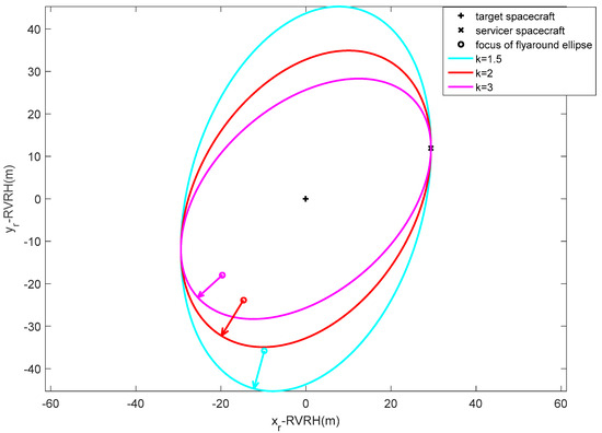
Figure 7.
Fly-around ellipses centered on target spacecraft.
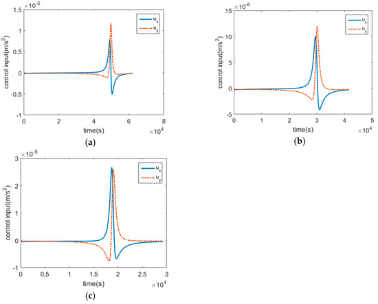
Figure 8.
Control inputs with typical fly-around speed parameters k are 1.5 (a), 2 (b), and 3 (c), respectively.
In Figure 7, the arrowed line segment also points from the focus of the ellipse to the periapsis. The simulation results show that by selecting different design parameters, the fly-around trajectories centered on the target spacecraft can be obtained, which verifies the effectiveness of the guidance law. However, different design parameters will affect the period and eccentricity of the fly-around trajectories.
3.3. Spatial Circle
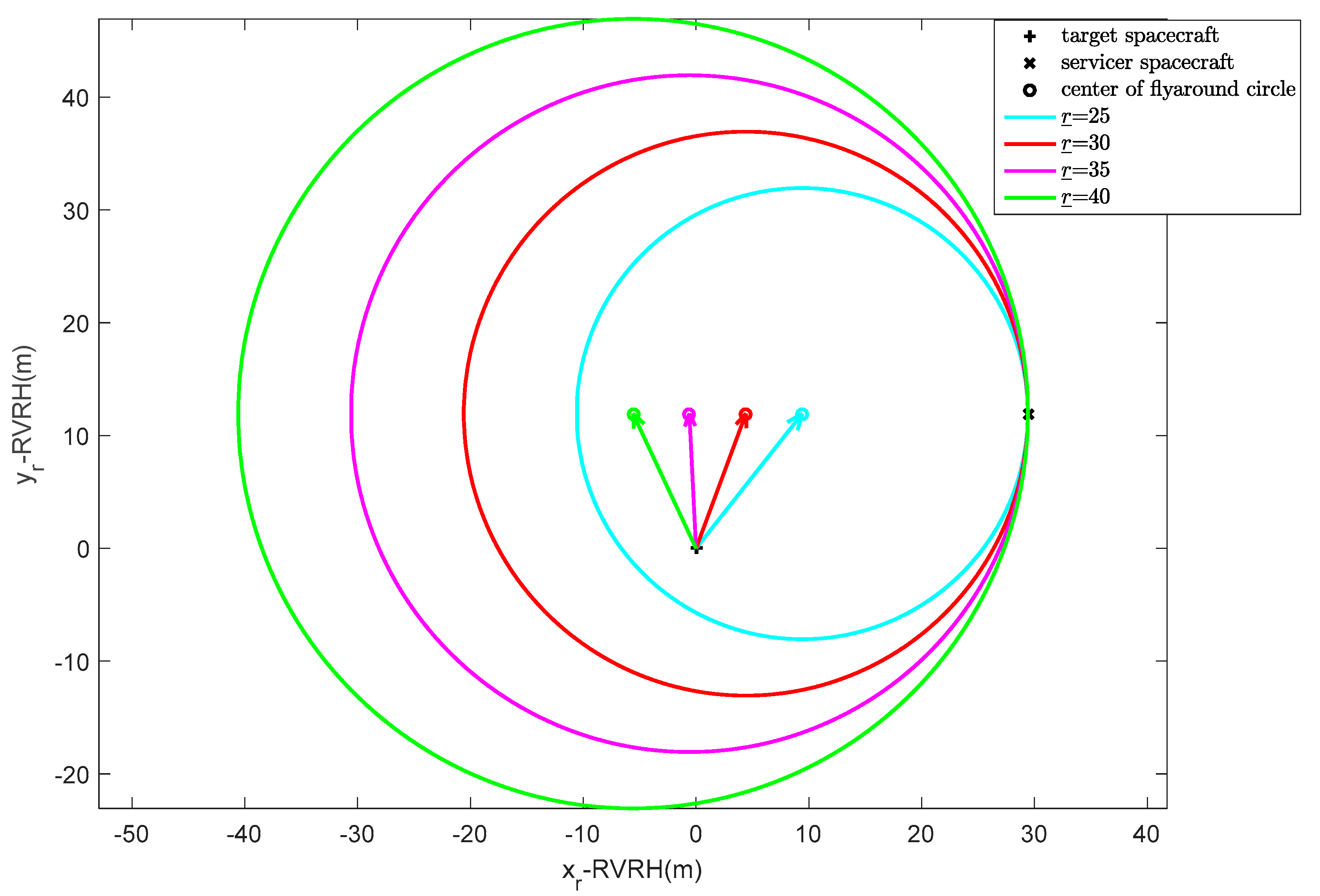
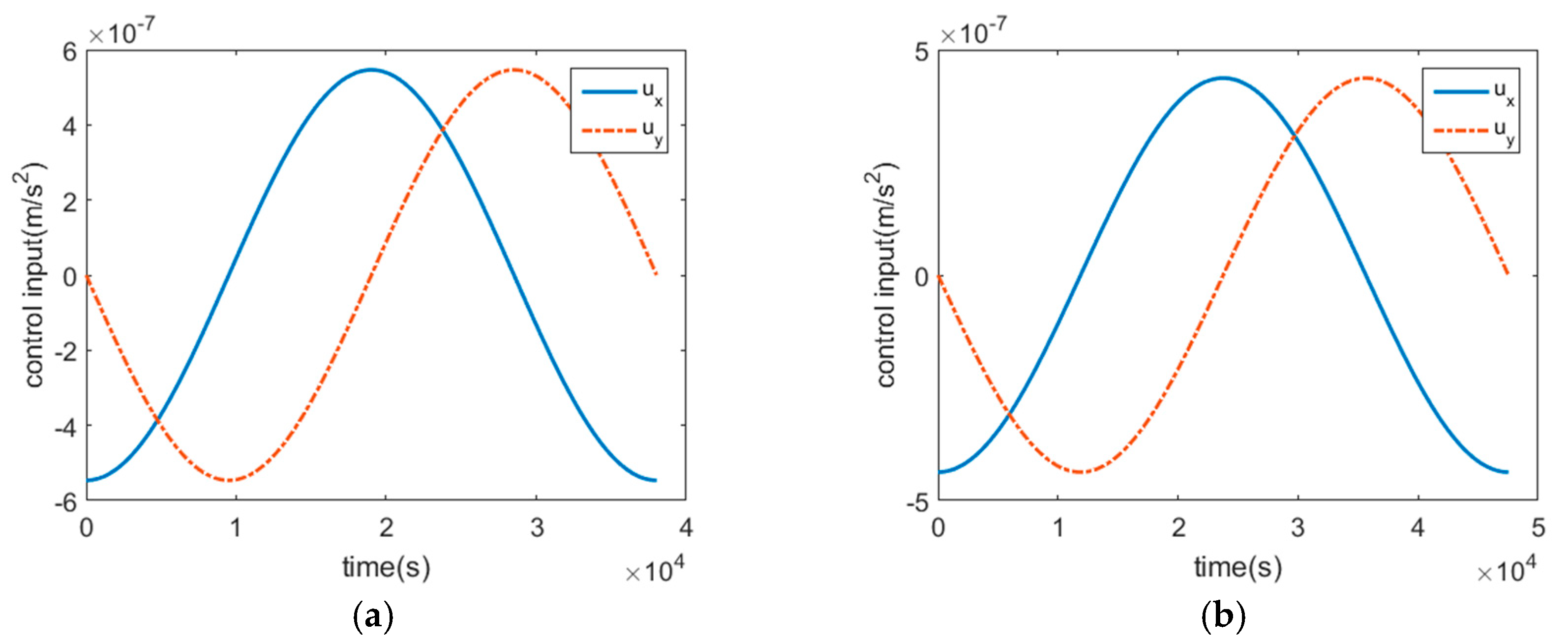
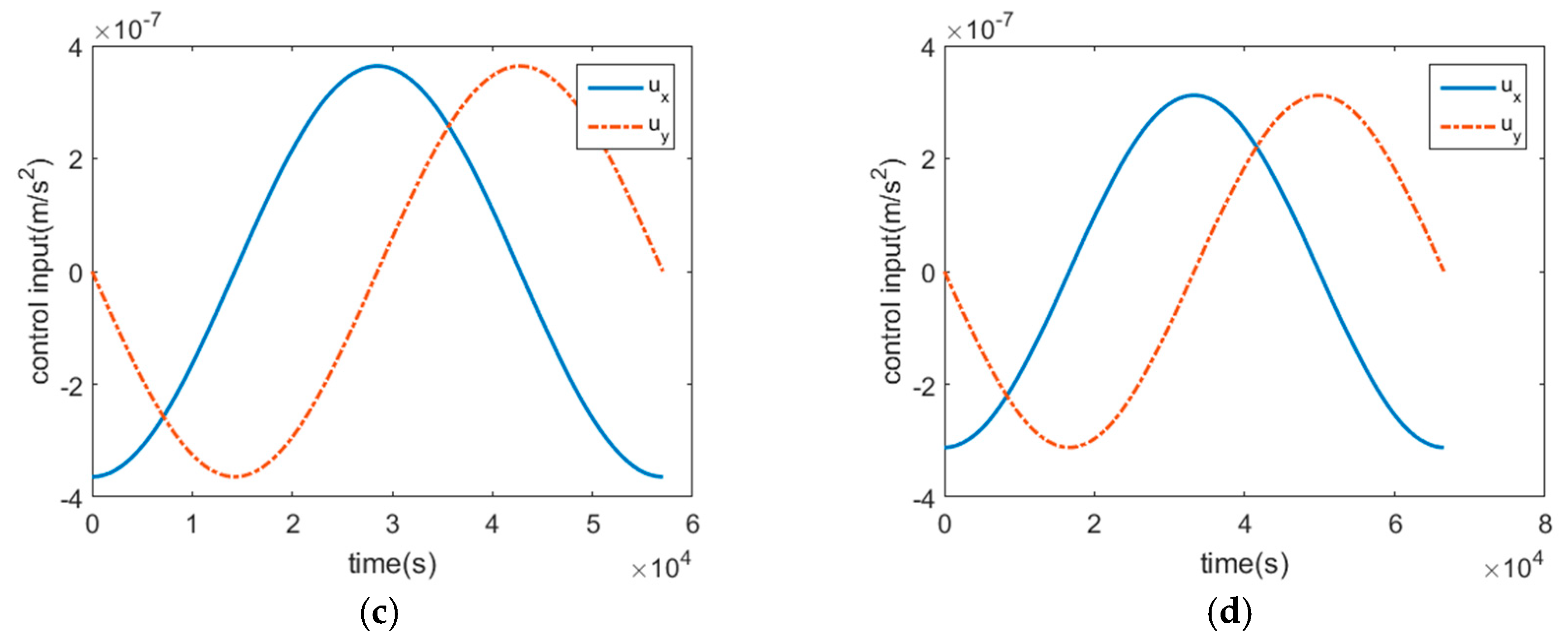
According to the above analysis, when the conditions and are met, the fly-around trajectory is a spatial circle. The position of the vector from the target to the center of the circle is . If the target is within the circle, the constraint needs to be met. Note that when the initial relative states are determined, the design parameters of the fly-around trajectory have only one degree of freedom, that is , and a series of fly-around trajectories can also be obtained. The simulation results are shown in Figure 9. Figure 10 shows the control inputs as a function of time.
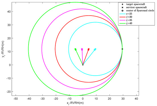
Figure 9.
Fly-around circles.
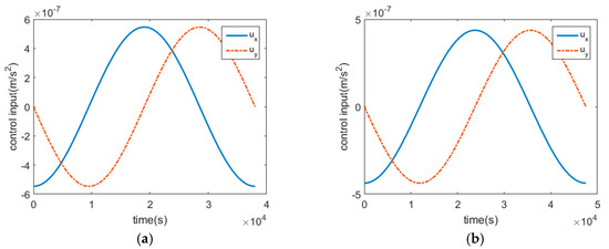
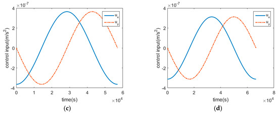
Figure 10.
Control inputs of fly-around trajectories where parameters are 25 m (a), 30 m (b), 35 m (c), and 40 m (d), respectively.
Specifically, if the expression holds, that is , the fly-around trajectory obtained is then the spatial circle centered on the target. The following focuses on the analysis and discussion of the spatial circle design where the reference orbit is a circular orbit. Referring to Equation (19), the coordinate component expression in the LVLH coordinate system of Equation (5) is described as follows:
According to Equation (4), the dynamics of the desired fly-around trajectory are as follows:
The solution of Equation (25) is as follows:
According to Equations (24) and (26), the control input can be calculated as follows:
According to Equation (27), if the fly-around period and initial relative states meet the following conditions:
Then the fuel consumption required for fly-around is zero, and Equation (28) is the necessary condition for circular formation in circular reference orbit under natural conditions.
3.4. Planar Fly-Around Trajectory
According to the spacecraft’s relative dynamics, when neglecting the perturbations, the relative uncontrolled motion in the z-axis direction of the target’s orbital plane will not diverge. Therein, the relative motion in the orbital plane is focused. The above discussion focuses on the motion in the plane determined by the initial relative states, and the obtained conclusions can be transplanted to the motion in the orbital plane. Accordingly, only the relative states in the orbital plane need to be considered, and also the control input in this plane. The planar fly-around trajectory also includes ellipses with the target spacecraft as the center or focus.
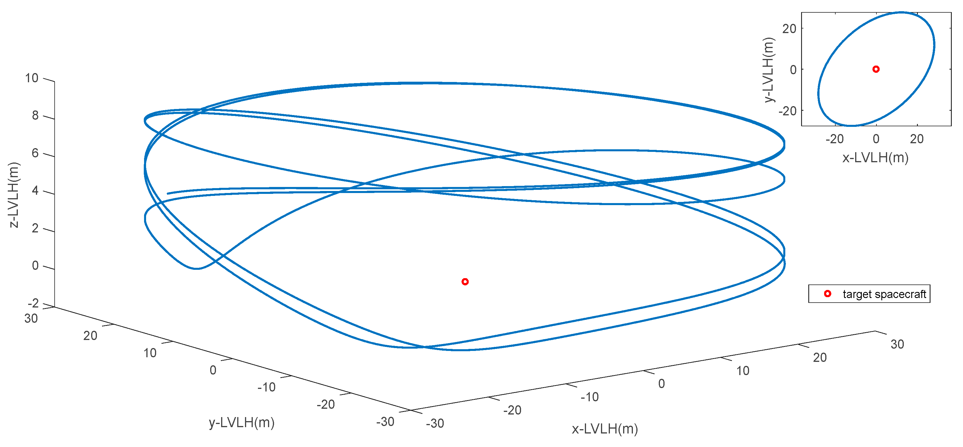
A simulation of a planar fly-around ellipse with the target spacecraft as the center is conducted. The orbit parameters of the two spacecraft are also the same as the parameters in Section 3.1. The parameter in Equation (23) is designed as . There is no active control in the z-axis direction. The simulation results are shown in Figure 11. Obviously, the fly-around trajectory is a projected ellipse, and there is a stable 3D configuration.
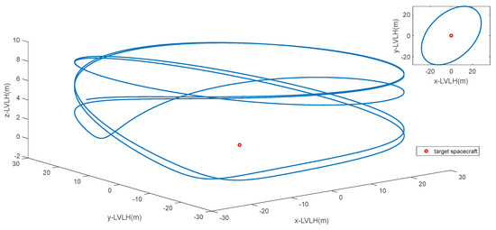
Figure 11.
Three-dimensional fly-around trajectory.
Particularly, when the target spacecraft is in a circular orbit, the circular fly-around configuration in the orbital plane centered on the target spacecraft is considered. Referring to Equation (24), the control input can be expressed as follows:
where initial relative state constraints and need to be satisfied. During a fly-around period, the fuel consumption in the x-axis direction is defined as follows:
Referring to Equation (29), the total fuel consumption can be expressed as follows:
According to Equation (31), the fuel consumption required in a fly-around period satisfies the following laws:
- (a)
- When the orbital angular velocity of the target and the fly-around speed are determined, that is, and are determined, the greater the fly-around radius, the greater the fuel consumption required to complete the fly-around;
- (b)
- When the ratio of the fly-around period relative to the orbital period of the target and the fly-around radius are determined, that is, and are determined, as the orbital height of the target increases, the orbital angular velocity decreases, and the fuel consumption also decreases;
- (c)
- When the orbital period of the target and the fly-around radius are determined, that is, and are determined, the magnification needs to be satisfied to achieve a fast fly-around. If expression or holds, as increases, the fuel consumption decreases accordingly. If expression or holds, as increases, the fuel consumption also increases.
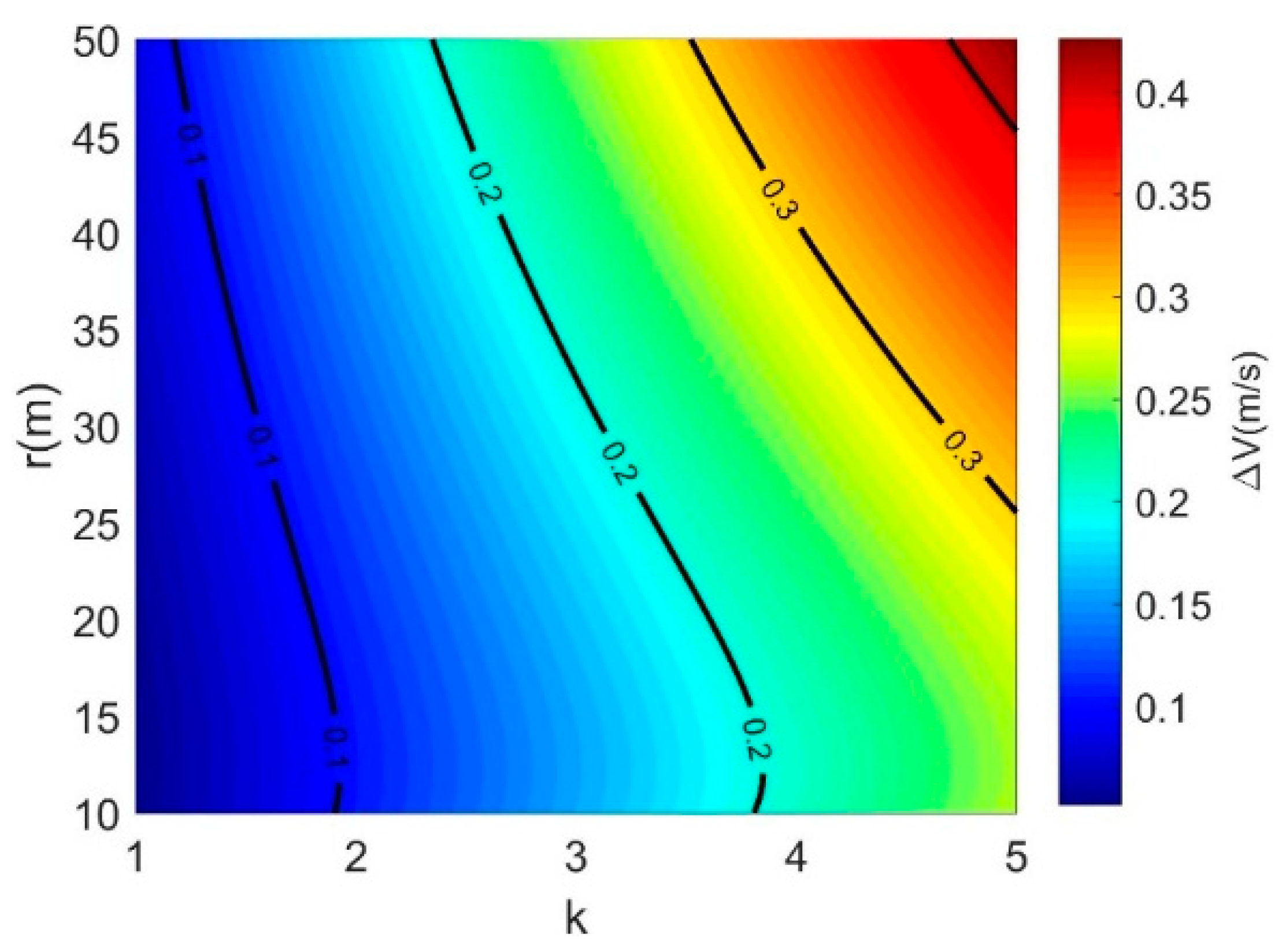
The simulations are conducted to illustrate the relationship between the fuel consumption, ratio k, and fly-around radius, as shown in Figure 12.
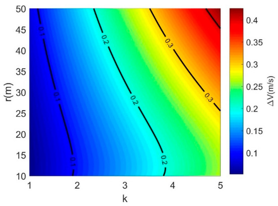
Figure 12.
Projected ellipse in the target’s orbital plane.
Additionally, it can be seen from Figure 12 that there is a trade-off between fuel consumption and fly-around speed and radius. If the fuel consumption is certain, the fly-around speed and the fly-around radius relative to the target can be negotiated, which is mainly dependent on the mission requirements.
4. Conclusions
A guidance law for a servicer spacecraft autonomously flying around a target is presented in this study. The objective of the proposed guidance law is to enable two spacecraft in any initial relative states to form a closed elliptical or circular fly-around formation through a continuous low-thrust maneuver. A new series of formation configurations are enriched and developed. The control input of the guidance law consists of the feedforward term and the artificial term. The artificial gravitational coefficient and the vector of the artificial gravity center are the two key design parameters, which affect the spatial position, size, shape, and period of the fly-around formation. Analysis and numerical simulations are conducted to estimate the influence of the two parameters, and the feasibility of the guidance law is evaluated. The advantages of the proposed guidance law can be summarized as follows:
- (1)
- The guidance law is intuitive and has good scalability. It is also suitable for circular reference orbit and elliptical reference orbit. It can also form a spatial fly-around formation and a specific planar formation. For proximity on-orbit operation missions, a stable fly-around formation can be quickly designed.
- (2)
- The fly-around trajectories are diverse. For certain initial relative states, there is a series of optional fly-around trajectories. According to different mission requirements, combined with the capacity of thruster and fuel constraints, reasonable design parameters can reach the desired goal.
Author Contributions
Conceptualization, X.W. and C.X.; methodology, X.W. and C.X.; software, X.W. and M.H.; validation, X.W. and M.H.; formal analysis, X.W.; investigation, X.W. and S.Z.; resources, X.W. and M.H.; data curation, X.W. and C.X.; writing—original draft preparation, X.W.; writing—review and editing, X.W. and S.Z.; visualization, X.W.; supervision, X.W. and C.X.; project administration, X.W. and C.X. All authors have read and agreed to the published version of the manuscript.
Funding
This research received no external funding.
Data Availability Statement
The original contributions presented in the study are included in the article, further inquiries can be directed to the corresponding author.
Conflicts of Interest
The authors declare no conflicts of interest.
References
- Li, R.; Deng, L.; Wang, Y.; Dai, H.; Duan, R. Target Detection for Synthetic Aperture Radiometer Based on Satellite Formation Flight. Sensors 2023, 23, 6348. [Google Scholar] [CrossRef] [PubMed]
- Wang, X.; Wang, Z.; Zhang, Y. Stereovision-based relative states and inertia parameter estimation of noncooperative spacecraft. Proc. Inst. Mech. Eng. Part G J. Aerosp. Eng. 2019, 233, 2489–2502. [Google Scholar] [CrossRef]
- Doszhan, N.; Alisher, I.G.G.; Roland, P. Ultra-High Accurate Attitude Determination and Control of Microsatellite Formation Flight. Balk. J. Electr. Comput. Eng. 2018, 6, 257–261. [Google Scholar] [CrossRef][Green Version]
- Chen, T.; Wen, H.; Hu, H.; Jin, D. On-orbit assembly of a team of flexible spacecraft using potential field based method. Acta Astronaut. 2017, 133, 221–232. [Google Scholar] [CrossRef]
- Aglietti, G.S.; Taylor, B.; Fellowes, S.; Salmon, T.; Retat, I.; Hall, A.; Chabot, T.; Pisseloup, A.; Cox, C.; Zarkesh, A.; et al. The active space debris removal mission RemoveDebris. Part 2: In orbit operations. Acta Astronaut. 2020, 168, 310–322. [Google Scholar] [CrossRef]
- Isobe, S.; Yoshimura, Y.; Hanada, T.; Itaya, Y.; Fukushima, T. Formation keeping control for deorbiting an uncooperative satellite by laser ablation. Adv. Space Res. Off. J. Comm. Space Res. COSPAR 2024, 74, 1916–1931. [Google Scholar] [CrossRef]
- Clohessy, W.H.; Wiltshire, R.S. Terminal guidance system for satellite rendezvous. J. Aerosp. Sci. 1960, 27, 653–658. [Google Scholar] [CrossRef]
- Bonin, G.; Roth, N.; Armitage, S.; Newman, J.; Risi, B.; Zee, R.E. CanX-4 and CanX-5 precision formation flight: Mission accomplished. In Proceedings of the 29th Annual AIAA/USU Conference on Small Satellites, Logan, UT, USA, 8–13 August 2015. [Google Scholar]
- Ivanov, D.; Ovchinnikov, M.; Tkachev, S. Nanosatellites Formation Flying Control Approaches Overview. IOP Conf. Ser. Mater. Sci. Eng. 2020, 984, 012023. [Google Scholar] [CrossRef]
- Joffre, E.; Wealthy, D.; Fernandez, I.; Trenkel, C.; Voigt, P.; Ziegler, T.; Martens, W. LISA: Heliocentric formation design for the laser interferometer space antenna mission. Adv. Space Res. 2020, 67, 3868–3879. [Google Scholar] [CrossRef]
- Liu, L.; Liu, J.; Wu, Y. Event-triggered coordinated control for multiple solar sail formation flying around planetary displaced orbits. Acta Astronaut. 2021, 184, 286–298. [Google Scholar] [CrossRef]
- Zhao, S.; Zhu, Q.; Tao, X.; Zhang, Y. Deployment of Constellation with Different Inclinations Using the Nodal Precession and Thrust. Sensors 2024, 24, 631. [Google Scholar] [CrossRef] [PubMed]
- Zhang, R.; Han, C.; Rao, Y.; Yin, J. Spacecraft fast fly-around formations design using the bi-teardrop configuration. J. Guid. Control Dyn. 2018, 41, 1542–1555. [Google Scholar] [CrossRef]
- Bai, S.; Wang, Y.; Liu, H.; Sun, X. Spacecraft fast fly-around formations design using the parallelogram configuration. Nonlinear Dyn. 2024, 113, 1041–1062. [Google Scholar] [CrossRef]
- Zhao, L.; Yuan, C.; Li, X.; He, J. Multiple Spacecraft Formation Flying Control around Artificial Equilibrium Point Using Propellantless Approach. Int. J. Aerosp. Eng. 2022, 2022, 8719645. [Google Scholar] [CrossRef]
- Scharnagl, J.; Kremmydas, P.; Schilling, K. Model Predictive Control for Continuous Low Thrust Satellite Formation Flying. IFAC-PapersOnLine 2018, 51, 12–17. [Google Scholar] [CrossRef]
- Zhao, L.; Zhao, K.; Li, H.; Huang, W.; Zhang, X.; Zeng, X. Loosely displaced formation-keeping control for satellite swarm with continuous low-thrust. Int. J. Adv. Robot. Syst. 2020, 17, 1–11. [Google Scholar] [CrossRef]
- De La Rue, W. Selecting the optimal propulsion system for manoeuvring during a satellite mission. In Proceedings of the AIAC 2023: 20th Australian International Aerospace Congress, Melbourne, Australia, 27 February–2 March 2023; pp. 581–586. [Google Scholar]
- Bai, S.; Han, C.; Rao, Y.; Sun, X.; Sun, Y. New fly-around formations for an elliptical reference orbit. Acta Astronaut. 2020, 171, 335–351. [Google Scholar] [CrossRef]
- Romero-Diez, S.; Hantsche, L.; Pearl, J.M.; Hitt, D.L.; McDevitt, M.R.; Lee, P.C. A Single-Use Microthruster Concept for Small Satellite Attitude Control in Formation-Flying Applications. Aerospace 2018, 5, 119. [Google Scholar] [CrossRef]
- Scharnagl, J.; Haber, R.; Dombrovski, V.; Schilling, K. NetSat—Challenges and lessons learned of a formation of 4 nano-satellites. Acta Astronaut. 2022, 201, 580. [Google Scholar] [CrossRef]
- Li, X.; Li, X.; Tang, L.; Yang, Z.; Yang, L. Development of a compact solar array drive assembly based on ultrasonic motor for deep space micro-nano satellites. Acta Astronaut. 2025, 228, 865–874. [Google Scholar] [CrossRef]
- Jia-Richards, O.; Lozano, P. Stage-based electrospray propulsion system for deep-space exploration with CubeSats. In Proceedings of the 2019 IEEE Aerospace Conference, Big Sky, MT, USA, 2–9 March 2019. [Google Scholar] [CrossRef]
- Wang, J.; Zhou, Q.; Zheng, W.; Diao, J. Trajectory tracking PID passivity-based control of spacecraft formation flying around Sun-Earth L2 point in the port-Hamiltonian framework. Adv. Space Res. 2024, 74, 5086–5099. [Google Scholar] [CrossRef]
- Pirat, C.; Richard-Noca, M.; Paccolat, C.; Belloni, F.; Wiesendanger, R.; Courtney, D.; Walker, R.; Gass, V. Mission design and GNC for in-orbit demonstration of cctive debris removal technologies with CubeSats. Acta Astronaut. 2017, 130, 114–127. [Google Scholar] [CrossRef]
- Chen, Z.; Dong, X.; Li, Y.; Hu, C. Formation Design for Single-Pass GEO InSAR Considering Earth Rotation Based on Coordinate Rotational Transformation. Remote Sens. 2020, 12, 573. [Google Scholar] [CrossRef]
- Wang, Z.; Gong, B.; Yuan, Y.; Ding, X. Incomplete Information Pursuit-Evasion Game Control for a Space Non-Cooperative Target. Aerospace 2021, 8, 211. [Google Scholar] [CrossRef]
- Wang, Y.; Topputo, F.; Hou, X. Analytic Gradients in Normalized Low-Thrust Trajectory Optimization with Interior-Point Constraints. J. Guid. Control Dyn. 2024, 47, 1980–1990. [Google Scholar] [CrossRef]
- Xu, L.; Zhang, G.; Qiu, S.; Cao, X. Reinforcement learning-based multi-impulse rendezvous approach for satellite constellation reconfiguration. Acta Astronaut. 2024, 224, 325–337. [Google Scholar] [CrossRef]
- Hsiao, F.-Y. Variation of Osculating Orbit Elements Using Low-Thrust Photonic Laser Propulsion in the Two-Body Problem. Aerospace 2022, 9, 75. [Google Scholar] [CrossRef]
Disclaimer/Publisher’s Note: The statements, opinions and data contained in all publications are solely those of the individual author(s) and contributor(s) and not of MDPI and/or the editor(s). MDPI and/or the editor(s) disclaim responsibility for any injury to people or property resulting from any ideas, methods, instructions or products referred to in the content. |
© 2025 by the authors. Licensee MDPI, Basel, Switzerland. This article is an open access article distributed under the terms and conditions of the Creative Commons Attribution (CC BY) license (https://creativecommons.org/licenses/by/4.0/).

