Abstract
A novel approach to model predictive control (MPC) with a decreasing horizon is analysed for guiding and controlling reusable launch vehicles (RLVs) during powered descent phases. Conventional MPC methods typically use receding horizons, where optimal control inputs are computed over fixed time intervals. However, when applied directly, these methods can cause a hovering-like behaviour, preventing the vehicle from reaching the landing platform, as the landing time is continually deferred at each iteration. The proposed solution addresses this problem by adjusting the prediction horizon dynamically, reducing its length over time. This dynamic adjustment is driven by a time-scaling factor and the time elapsed since the previous MPC iteration. Optimal control solutions are derived through convex optimization techniques. To evaluate the algorithm’s robustness against initial conditions, a Monte Carlo analysis is performed by varying initial position, velocity and mass. This method can also be used as a viable methodology for selecting tuning parameters for the MPC to ensure a successful and safe landing for a wide range of initial conditions.
1. Introduction
The development of technologies that allow for vertical descent and landing of rockets has proven to be a game changer by reducing the cost barrier to space access. Thanks to this technology, new companies, e.g., SpaceX, can offer competitive prices for launch services to new space actors and enterprises [1]. Likewise, they enable planetary missions to touch down on previously selected landing sites deemed interesting for their scientific value. Examples of this are the Mars Science Laboratory mission [2], the MARS 2020 mission, and the Tianwen-1 Mars mission [3].
Guidance and control during the powered descent and landing of reusable launchers is one of the most complex challenges that characterise such systems, involving innovative solutions from a technical and practical perspective. The challenge of achieving a soft landing for a fast free-falling launcher lies in the precise control of its dynamics. This involves a complex interplay of forces, where the thrust must be modulated and re-oriented to counteract the effects of gravity and atmospheric drag [1]. By adjusting the thrust vector, the descent can be stabilised, allowing for adjustments to be made in real-time to ensure a gentle touchdown. This process requires advanced algorithms and control systems capable of responding to the rapidly changing conditions of a free fall, ensuring that the launcher can navigate to the desired landing site and achieve a controlled and safe landing [4].
The development of powered descent guidance algorithms based on optimal control theory began in the 1960s during the Apollo era as part of the lunar landing program [5,6,7]. More recently, the space sector has renewed its interest in this type of technology as part of the Mars exploration missions at the end of the last century and beginning of the 2000s through the utilisation of constrained optimisation methods. Such algorithms were further optimised by the application of convex programming [8,9], which demonstrated that a second-order cone programming (SOCP) set of equations can be used to solve the powered descent problem through interior point methods. Other guidance methods have been successfully applied to perform smooth landings on planetary bodies. Among other examples are the Mars Science Laboratory Entry, Descent, and Landing System, which followed a 3D polynomial trajectory computed at the beginning of the landing phase and performed a powered approach to the Martian surface [2] and the polynomial guidance strategy used by the Tianwen-1 mission to perform a diversion manoeuvre during the powered descent phase [3]. Nevertheless, whereas polynomial powered descent guidance is computationally efficient and sufficient for small diversions, constrained optimisation methods solve for globally fuel-optimal and constrained diversions that allow for the inclusion of the particularities of the spacecraft in the guidance strategy [9,10]. For the particular case of landing a reusable launch vehicle (RLV), polynomial guidance might not be suitable due to rapid changes in the flight conditions, as mentioned before.
The last decade has seen a significant surge in the development of advanced guidance and control systems for launch vehicles. The incorporation of convex optimisation models has revolutionised the precision with which these vehicles can be manoeuvred, accounting for both translational and rotational dynamics. This progress in six degrees-of-freedom (6 DoF) modelling enhances the accuracy and reliability of launchers, marking a substantial advancement in aerospace engineering and space exploration capabilities. In [11], the methodology of successive convexification, a form of sequential convex programming (SCP) was used for solving the powered descent guidance problem. Within that study, the algorithm employed virtual control and trust region modifications to facilitate convergence of the problem. In [12], a similar approach was used by integrating aerodynamic controls within a two-dimensional framework, simulating conditions over a flat Earth model. Additionally, in [13], the control optimiser leveraged the atmospheric drag energy to enhance efficiency, representing another innovative application of this technique. These advancements underscore the growing reliance on convex models to optimise the performance and safety of reusable launch vehicles and landers during the final phases of descent and landing. A more detailed survey on optimization-based space vehicle control was performed in [14], not only for a powered landing scenario but also for other guidance and control challenges such as rendezvous and proximity operations, constrained reorientation, and orbit transfer and injection. In [15], an assessment of the coupling between the guidance and control techniques was carried out for different RLV recovery strategies and controllability challenges. Additionally, alternative guidance strategies are currently being studied such as evolutionary optimisation, tree searches, and machine learning [16,17]. For instance, a trained neural network was used in [18] to solve fuel-optimal powered descent guidance in lunar pinpoint landing, and closed-loop MPC guidance with deep neural networks was used for landing a rocket’s first stage [19].
Nevertheless, the challenges of Earth descent and landing for RLVs are indeed complex, with atmospheric drag, winds, and structural flexibility posing significant risks to the integrity of the manoeuvres. Open-loop control schemes, which rely solely on preplanned trajectories, are often insufficient due to their inability to adapt to dynamic environmental conditions. In contrast, closed-loop control systems, such as model predictive control (MPC), offer a more robust solution by continuously adjusting the vehicle’s trajectory in response to real-time sensor data. MPC can predict future states of the RLV and make necessary adjustments to ensure a safe and accurate landing [20,21]. MPC had been widely used for managing the complex processes of industries like chemical and oil processing [22,23], where changes occur over longer periods. However, applying MPC to RLVs during powered descent involves rapid dynamics and requires real-time computational speed, robustness against disturbances, and precise handling of constraints. Typically, MPC uses a receding horizon strategy where the optimal control is always calculated for a fixed period of time shifting at each iteration step [22]. However, the direct implementation of such schemes in a powered descent scenario is not trivial, and it can lead to unexpected behaviours such as hovering-like trajectories with the vehicle never reaching the landing target. This is shown in [24], where an optimal strategy for setting the prediction horizon duration was developed as a solution to counter the impossibility of finding a fixed receding horizon for the guidance and control of RLVs. In addition, Scharf et al., in [25,26], used an onboard time-of-flight search algorithm to obtain the best prediction horizon for the optimisation problem at each iteration of the G-FOLD algorithm.
This paper introduces a new algorithm designed to simplify the time-length update phase within an MPC algorithm. It details an iterative method that adjusts the horizon length using a specific update factor. The resulting solution, while sub-optimal, might demand significantly less computational power than previously optimised algorithms, such as those mentioned in [24], as it predefines the prediction horizon to use at each iteration instead of including it as a variable to optimize in the cost function. Other earlier methods aimed to determine the optimal horizon at the beginning of each MPC iteration [26] require multiple problem-solving instances per iteration and thus are not computationally efficient. The proposed method markedly reduces the iterations needed to establish a viable time horizon, thereby reducing the computational time. This feature is particularly advantageous for real-time embedded system applications. This paper completes the work presented in [27], varying the initial conditions of the numerical simulations and completing the study with a Monte Carlo analysis of the robustness of the algorithm with respect to the variability of the initial state vector, which benefits the proposed method to accurately tune the MPC algorithm and prevents possible issues during flight.
The paper is organised into the following sections: Section 2 defines the set of equations and constraints of the guidance problem, and a convexification of this set of equations is proposed in Section 3 so that an MPC algorithm can be developed later in Section 3.2. Next, the simulation results and a Monte Carlo analysis in Section 4 prove the robustness of the algorithm against different initial and environmental conditions. Finally, Section 5 provides the concluding remarks and future work.
2. Problem Statement
In this section, the rocket plant used for the simulation is presented along with a mathematical definition of the landing problem. This section has been written in an abridged format, as the main theoretical derivation was presented in [27].
2.1. Model
The model used for the simulations is a point-mass two-dimensional model and is subjected to the forces generated by the thrust T of its engines and atmospheric drag D (see Figure 1):
where is the ascent/descent angle of the RLV, is the specific impulse of its engines, and is the gravity force at sea level. The orientation of the RLV is not explicitly represented in the set of Equation (1), although the tangent of the thrust vector is considered to be the orientation of the RLV, , fixing the thrusters to the body.
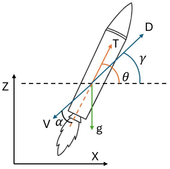
Figure 1.
RLV model variables as presented in Equation (1).
The aerodynamic drag D is obtained from Equation (2), where is the air density at a given altitude, V is the magnitude of the velocity relative to the atmosphere, which includes the RLV velocity and the wind velocity, S is the area of the launcher exposed to atmospheric flow, and is the drag coefficient. The angle of attack is defined as the difference between and (see Equation (3)). This model is further developed in [27].
2.2. Definition of Landing Problem
A set of constraints defines the problem (a two-boundary value problem (TBVP)) to be solved, including the initial and desired final values of the state vector:
where and are the initial and final time. The landing pad is assumed to be fixed in the origin of the reference frame (Constraint (5)) and needs to be reached by the RLV with zero velocity, in order to have a soft landing.
The TBVP assumes a cost function that minimises the required thrust:
The list of considered constraints is derived in [8,27] and contains the following equations:
where is an orientation boundary that changes over time.
3. Model Predictive Control
The MPC strategy used is illustrated in Figure 2, where the RLV’s physical model (Equation (1)) is controlled by an optimal thrust profile derived from a convex optimisation solver (SeDuMi [28]). The solver employs the convexified set of constraints and equations of motion outlined in Section 3.1. The implementation of the decreasing horizon model predictive algorithm is then detailed in Section 3.2.
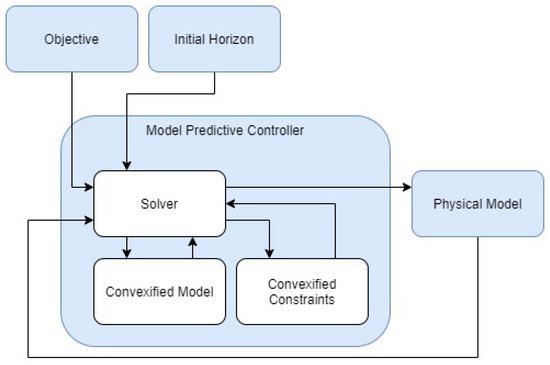
Figure 2.
Flowchart of MPC Strategy [27].
3.1. Convexification of the Problem
Two steps must be performed to turn the landing problem into a semidefinite programming (SDP) problem [8], which can be solved by a convex solver. The first step is to transform the non-convex constraints into a convex form following the process described in [8]. In the landing problem presented in Section 2.2, the sources of non-convexity are (1) the change of mass in the last row of Equation (1), which is tackled by a change of variable as in Equation (12), and (2) the thrust limit in Constraint (7), which is dealt with by introducing a slack variable as in Equation (13) [8].
After a series of steps followed in [27], the last equation of Equation (1) can be rewritten as Equation (14).
The objective index defined in Equation (6) can now be reformulated with the new variable as Equation (15).
Thus, the state variables can be updated at each iteration step of the prediction phase in the MPC by using the linearised set of equations of motion in Equation (16), where the atmospheric drag is not included and therefore it is considered as an external disturbing factor for the controller.
3.2. Decreasing Horizon MPC
The proposed modification to the MPC method is based on the adjustment of the horizon length to solve the issues when a receding horizon is applied. The main issue with the receding horizon strategy for the TBVP is that the landing time is always postponed, and therefore the guidance algorithm will generate the guidance law to land in the future until the problem becomes infeasible due to the lack of propellant (see [27] for a comparison between both strategies) and to allow the RLV to land. For this purpose, it is necessary to define several time-related parameters, which will define how and when the prediction horizon is updated:
- (a)
- Terminal Horizon time (): which serves for setting the global desired time to be landed. This represents the upper-bound limit for touch down, that in any case can happen anytime before.
- (b)
- Prediction Horizon time (): time used in the prediction step by the optimisation solver.
- (c)
- : time between each MPC iteration when the optimiser recalculates the optimal solution by getting the updated state of the RLV.
- (d)
- : time between each of the prediction states computed within the same prediction horizon.
- (e)
- Update Factor (): determines when and by which rate and are decreased. Its value must be set between 0 and 1.
Algorithm 1 and Figure 3 outline the operation of this new strategy. In the first step of the algorithm, the initial values for the new parameters are set. Two nested loops are then executed. The outer loop (line 2) updates and at each iteration and continues until the prediction horizon becomes smaller than the iteration time step . The inner loop (line 3) handles the prediction and calculates the optimized control for the RLV. The prediction step is carried out by the function convexOptimiser(X, , ), which uses the given and , solving the optimization problem in Equation (15) and implementing the equations and constraints described in Section 3.1. Once the outer loop completes, the algorithm applies the final segment of the control signal U to the RLV to complete the landing manoeuvre (line 10).
| Algorithm 1 Decreasing Horizon MPC Algorithm |
| 1: Define , , , , UF and |
| 2: while do |
| 3: for do |
| 4: U = convexOptimiser(X, , ) |
| 5: Apply U for |
| 6: end for |
| 7: Update |
| 8: Update |
| 9: end while |
| 10: Apply the rest of U |
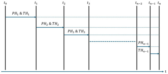
Figure 3.
Generalisation of the decreasing MPC algorithm.
Figure 3 illustrates how the update of and progresses over time within the algorithm. Starting with the initial values , , , and , the horizons and are applied over a time equal to . At this point, and are calculated by multiplying and by , as shown in lines 7 and 8 of Algorithm 1. The algorithm then proceeds with these updated horizons for the next iteration. It is important to note that only the terminal and prediction horizons are adjusted during the execution of the MPC algorithm. The process continues until the prediction horizon becomes shorter than the iteration step , represented as in Figure 3. At this point, the RLV uses the remaining portion of the predicted control generated by the MPC. As discussed in Section 4, the selection of horizon times and initial parameters is critical to the algorithm’s performance, and these values vary depending on the problem’s initial conditions.
4. Numerical Results
The performance of the proposed MPC algorithm for reusable launch vehicle (RLV) scenarios is evaluated through numerical simulations. This section presents several test cases simulating landings on Earth using the first stage of SpaceX’s Falcon 9 rocket [29]. The methodology follows the approach outlined in [27], with the addition of a Monte Carlo analysis to assess the robustness of the MPC algorithm with respect to varying initial conditions of the RLV. The aim is to further validate the capability of the proposed algorithm in achieving a successful RLV landing in a realistic scenario, complementing the results presented in [27]. The chosen scenario models the landing of the Falcon 9’s first stage, beginning from an initial position of , and initial velocities of and . These values are used as the initial state vector for solving the problem.
The relevant parameters for the rocket and the environment are provided in Table 1 and Table 2, respectively. For the simulations, only one engine of the rocket is considered. The initial mass of the RLV in each scenario is determined by the remaining fuel mass at the start of the landing phase. The simulations are conducted using the lower atmosphere of Earth as the environmental model.

Table 1.
Falcon 9 first stage parameters used in the simulations.

Table 2.
Earth parameters used in the simulations. Data from [30].
4.1. Understanding the Feasibility Region of the Optimisation Problem
Before analysing the performance of the proposed MPC algorithm, a study is carried out to understand the suitability of the convex optimiser to solve the problem. This is achieved through a series of Monte Carlo and parametric analyses that allow a better comprehension of the feasible region with respect to the prediction horizon and the initial conditions. A sensitivity analysis regarding the initial conditions and prediction horizon duration was performed in Section 4.1.1 of [27], with a range of initial conditions that still apply for those used for the simulations in this study (see Table 3).

Table 3.
Monte Carlo minimum and maximum boundaries for the initial conditions of the problem [27].
4.1.1. Finding the Applicable Ranges of the Prediction Horizon for Different Initial Velocities
The second step of the feasibility study is an analysis of the effect of the initial magnitude in the two components of the velocity and [27]. A parametric analysis is executed to understand the feasible range of values for each V considered. Table 4 describes the initial conditions of the analysis while the velocities are obtained from Table 3.

Table 4.
Initial conditions for the parametric analysis of the prediction horizon of the problem.
The parametric analysis results can be seen in Figure 4. In Figure 4a, the values for the problem show a global minimum of around and a radius of . The propagation of these initial velocities starting at the initial position allows for a clear understanding of the physical interpretation of the location of such minimum. These velocity values bring the RLV close to the landing site without the need for thrust, and therefore they allow for minimisation of the eventual corrections of the trajectory.
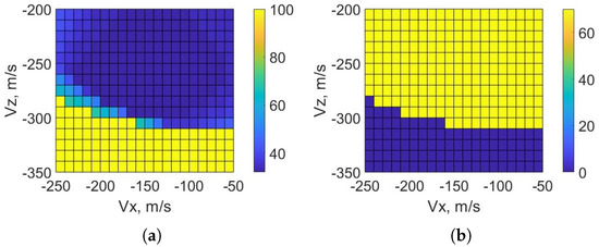
Figure 4.
Parametric Analysis of the initial velocity for the optimisation problem: (a) minimum PH and (b) maximum PH in seconds. The values in yellow in (a) and dark blue in (b) define the infeasible region of the problem.
In Figure 4b, the region with the maximum feasible values is in the upper-right corner. Such a region of maximum feasible is due to the lower thrust needed to overcome the initial velocities, being these with smaller magnitudes compared to the other cases, and therefore a higher quantity of fuel still available to descend slowly or even hover before touching the ground. Moreover, the values in yellow in Figure 4a and in dark blue in Figure 4b when is close to represent the cases in which the problem is unfeasible.
4.2. Analysis of the Performance of the Proposed MPC
After understanding the applicability of the presented optimiser for the landing scenario, the performance of the proposed MPC algorithm is analysed. Firstly, a parametric analysis is carried out to understand where the feasible region is with respect to the parameters of the MPC to be tuned. These parameters are the prediction horizon , the terminal horizon , and the update factor . Afterwards, an optimal trajectory obtained within the feasible region is discussed.
4.2.1. Finding the Applicable Ranges of Terminal Horizon and Update Factor
The feasible ranges for and need to be identified based on the findings in Section 4.1. To this end, a parametric test with 1188 cases was conducted across a broad range of values, see Table 5. It was determined that a and a within the range are suitable for solving the problem. The feasibility of the problem is assessed by verifying that the constraints outlined in Section 2.2 are satisfied and by comparing the state of the RLV at the end of each MPC run with the final objective, which is . The problem is considered solved if the position and velocity errors fall within specified margins: and , respectively.

Table 5.
Range of values for the TH, UF, and PH for the parametric analysis of the TH and UF based on the result obtained in Section 4.1.
The execution of the set of scenarios revealed a zone in which the problem is feasible, as seen in Figure 5. From the set containing 1188 cases, 348 were feasible. The first detail seen in Figure 5 is that is the minimum feasible PH. This is explained by the fact that the MPC algorithm will not solve the problem if the convex optimiser does not. For , the problem is feasible for almost any selected and a greater or equal to . As the increases, the feasible region is restricted to a lower , i.e., between and for and . The higher boundary of continues decreasing until there is only for . In a similar manner, as the increases, the increases. For the cases with lower , there are feasible solutions for all the values of with various values of , while in the upper part of Figure 5 the main feasible region is constrained to and with . The scenarios comprised by are a good example of the tendency of the feasible region with respect to the selected value of . Initially, it covers the full spectrum of selected values of when and ends with only one feasible solution with and . There were other feasible cases seen in Figure 5, but as they were isolated, they were not considered to be part of the main feasibility region.
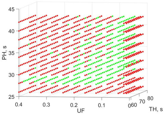
Figure 5.
Feasible (green) and unfeasible (red) cases of the parametric analysis of , , and .
4.2.2. Optimal Trajectory
The final step to discuss is the performance of the MPC algorithm in a feasible scenario. The selected case, part of the set analysed in Section 4.2.1, considers parameters of , , and .
Figure 6 illustrates the trajectory followed by the RLV during the powered descent. The red vectors represent the thrust applied at each moment, with the largest thrust exerted at the start and end of the landing. This is further confirmed by Figure 7, which displays the state and control vectors for the landing case. In Figure 7e, the thrust follows a bang–bang profile, reaching its maximum for extended periods at both the beginning and end of the simulation. Meanwhile, Figure 7f shows that the thrust angle starts at and gradually converges towards for a vertical landing.
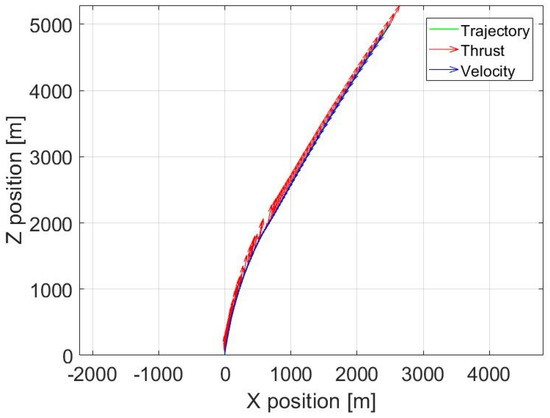
Figure 6.
MPC: Landing trajectory with thrust vector.
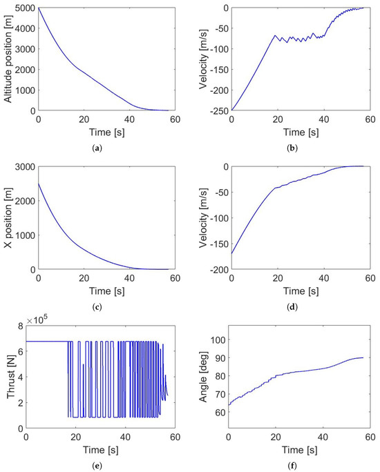
Figure 7.
MPC: Nominal scenario landing variables for the RLV. Subfigure (a) shows its altitude against time, (b) shows its over time, (c) shows its X position against time, (d) shows its over time, (e) shows the used thrust norm, and (f) shows the thrust angle .
In Figure 6 and Figure 7a, the altitude drops rapidly during the first , while the proposed MPC algorithm simultaneously reduces the , as shown in Figure 7b, counteracting the initial velocity. Notably, between and , the remains nearly constant to allow the RLV to approach the target on the X-axis, as seen in Figure 7a–d, resulting in a slower decrease in altitude. During the final phase of the descent, the MPC reduces the magnitudes of both the and components, achieving a safe landing at the target position. The final state vector of the RLV is , which satisfies the specified margins. The final mass is , greater than the dry mass of the first stage of the Falcon 9 rocket.
Although not shown in Figure 7f, some cases exhibit instantaneous changes in the thrust angle due to the absence of a constraint on the initial control actions. As a result, at each step of the MPC algorithm, the initial may differ from its previous value. Future research activities will focus on including this constraint in the algorithm to ensure that the optimizer takes the RLV’s current orientation into account. Additionally, the model in Equation (1) does not consider the rotational dynamics of the RLV, meaning that the computed is assumed to be achieved instantaneously. Nonetheless, these instantaneous jumps in are limited to . It is reasonable to expect that if attitude dynamics were included in the simulation model, the angle would be reached over a shorter period than the characteristic time of the simulation.
4.3. Monte Carlo Analysis of the Nominal Scenario Boundaries for the Selected PH, TH and UF
Once a nominal scenario has been studied and the values of the PH, TH, and UF have been selected, the last step is to understand how robust the algorithm is with respect to uncertainties in the initial state of the vehicle. Using the chosen values of the PH, TH, and UF, a Monte Carlo analysis is performed to find the boundaries of the feasibility region in each of the elements of the state vector.
Table 6 shows the minimum and maximum values for the uniformly distributed random points characterising the analysis. The range of values considered in each component of the position is 1000 m, from 2000 m in X and 4500 m in Z, up to 3000 m and 5500 m, respectively. The velocity components are constrained to m/s in and m/s in , which means a range of 90 m/s and 100 m/s. The initial mass studied covers from a minimum of tonnes up to tonnes, which means that the percentage of the fuel goes from to .

Table 6.
Boundaries of the Monte Carlo analysis of the selected , , and .
4.3.1. Monte Carlo Analysis with Fixed Initial Velocity
The first case studied is the sensibility of the proposed MPC algorithm to variations of the initial position and mass. Figure 8 presents the results of the 500 simulations. Figure 8a compares the variability of the problem with respect to the initial position. It displays a feasible region for all m for all the range of altitudes considered, but going up to m when the altitude is higher. Additionally, it presents an unfeasible region in the lower-right corner when the initial horizontal distance is greater and the altitude is lower, which shows the relation between initial position and velocity. As the velocity is fixed, there is a boundary in which the problem becomes unfeasible for the MPC algorithm to solve. This relates to what was stated previously in Section 4.1.1. The unfeasible cases in the feasible region are caused by an initial mass too small or too big, as seen in Figure 8b when m.
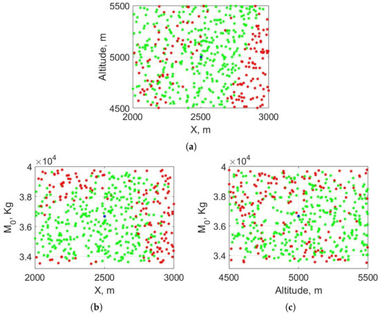
Figure 8.
Monte Carlo results with variable initial position and initial mass. Subfigure (a) compares initial altitude vs horizontal range, Subfigure (b) compares initial mass vs horizontal range, Subfigure (c) compares initial mass vs. altitude. Results in green are feasible, in red are unfeasible, and the blue points mark the initial conditions of the nominal scenario. These three subfigures represent a three-dimensional figure considering X, altitude, and initial mass . Feasible and unfeasible close points have different values in the missing axis of each subfigure or are close to a feasibility boundary.
In Figure 8b,c, the initial mass is compared to each position component. Analysing both subfigures, it can be seen that, for a fixed initial velocity, the component that affects the feasibility the most is X. For m, there is a clear feasible zone, except for two regions where the mass is too high ( tonnes) or too low ( tonnes) and m. Figure 8c contains feasible solutions in the range of considered altitudes with a higher difficulty in landing the RLV correctly when the mass is close to the upper limit.
4.3.2. Monte Carlo Analysis with Fixed Initial Position
The second Monte Carlo test maintains the initial position as in the nominal scenario and varies the initial velocity and mass according to Table 6. The results obtained after 500 iterations are represented in Figure 9.
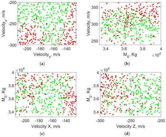
Figure 9.
Monte Carlo results with variable initial velocity and initial mass. Results in green are feasible, results in red are unfeasible, and the blue points mark the initial conditions of the nominal scenario. Subfigure (a) shows the results with respect to the velocity components (, ) and Subfigure (b) shows the results with respect to the velocity norm V and the initial mass . Subfigures (a,c,d) represent three-dimensional figure considering , and .
On Figure 9a, the feasible region represents all the cases in which the MPC algorithm was able to overcome the initial velocity. When the initial magnitude of is small ( m/s), the RLV is not able to reach the landing target, especially as the initial becomes higher. Moreover, there is an unfeasible region when m/s and m/s, when m/s, as seen in Figure 9b. This subfigure shows an unstable region around the nominal scenario conditions, but its feasibility is better explained in Figure 9c,d, where the initial mass is compared with each velocity component. The proposed MPC algorithm is robust for the zone around the nominal condition in Figure 9c, particularly when m/s and independently of . As increases, the problem becomes more difficult to solve, in the same manner as in Figure 9d when reaches 300 m/s.
4.3.3. Monte Carlo Analysis with Fixed Initial Mass
The last Monte Carlo analysis for assessing the robustness of the MPC algorithm consists of 500 cases in which the initial mass was fixed and the position and velocity variate. Figure 10 presents the results obtained and reinforce the lessons already learned in the previous Section 4.3.1 and Section 4.3.2. Specifically, in Figure 10a, the problem becomes harder to solve when the horizontal distance X with respect to the landing pad increases and, in Figure 10b the problem cannot be consistently solved in the bottom right region when the initial is smaller and the initial rises.
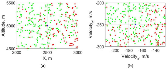
Figure 10.
Monte Carlo results with variable initial position (a) and initial velocity (b). Results in green are feasible, those in red are unfeasible, and the blue points mark the initial conditions of the nominal scenario.
5. Conclusions
This paper further analyses the robustness of a proposed MPC strategy for the powered descent of an RLV. The strategy adjusts the prediction horizon using an update factor, allowing the RLV to land within a specified terminal horizon. The paper highlights the advantages of this approach over receding horizon MPC methods, reducing the need for an online search of a suitable prediction horizon when it is not fixed [10]. It can be tuned by properly setting the initial , , and values.
The numerical simulations and the tuning carried out within this paper show that this approach is viable and promising. The presented tuning strategy can be easily automatised and applied to systems with different RLVs and initial conditions, leading to different optimal sets of , and . The robustness of the tuning strategy, as well as the overall MPC algorithm, was assessed by analysing the performances and the feasibility regions by varying, under a Monte Carlo approach, the initial conditions of the vehicle. The qualitative interpretation of the results leads to stress the importance of the initial horizontal distance between the RLV and the landing site, and the initial vertical component velocity. A key parameter considered within these analyses was the propellant mass, which is strongly affecting the capability of the rocket to land. Sharp feasibility boundaries were indeed identified when initial parameters were pushed out of reasonable ranges. In the presented case of the landing of a Falcon 9 stage, the maximum horizontal distance could not be bigger than 2800 m and the initial vertical descent velocity could not exceed approx. 280 m/s. In such cases, the RLV could run out of fuel or could not be able to slow sufficiently fast the motion before touching the ground.
Preliminary results of the current work by the authors have been presented in [31], describing further research of a similar strategy on a six-DoF rigid body model with translational and rotational dynamics. Future work will test possible failure scenarios, i.e., an engine failure, and how the proposed MPC algorithm copes with them. Alternative future works will explore the possibilities of using artificial intelligence for the selection of the prediction horizon, i.e., tree search algorithms, as described in [16].
Author Contributions
Conceptualization, G.Z.P. and L.F.; methodology, G.Z.P. and L.F.; software, G.Z.P.; validation, G.Z.P. and L.F.; investigation, G.Z.P. and L.F.; writing—original draft preparation, G.Z.P.; writing—editing, G.Z.P.; writing—review, L.F. and E.G.-G.; visualization, G.Z.P.; supervision, L.F. and E.G.-G. All authors have read and agreed to the published version of the manuscript.
Funding
This research received no external funding.
Data Availability Statement
Supporting data is available upon request to the corresponding author.
Conflicts of Interest
The authors declare no conflicts of interest.
References
- Blackmore, L. Autonomous precision landing of space rockets. Bridge 2016, 46, 15–20. [Google Scholar]
- Prakash, R.; Burkhart, P.D.; Chen, A.; Comeaux, K.A.; Guernsey, C.S.; Kipp, D.M.; Lorenzoni, L.V.; Mendeck, G.F.; Powell, R.W.; Rivellini, T.P.; et al. Mars Science Laboratory Entry, Descent, and Landing System Overview. In Proceedings of the IEEE Aerospace Conference Proceedings, Big Sky, MT, USA, 1–8 March 2008. [Google Scholar] [CrossRef]
- Huang, X.; Xu, C.; Hu, J.; Li, M.; Guo, M.; Wang, X.; Zhao, Y.; Hua, B.; Wang, Y. Powered-descent landing GNC system design and flight results for Tianwen-1 mission. Astrodynamics 2022, 6, 3–16. [Google Scholar] [CrossRef]
- Gallaher, M.; Coughlin, D.; Krupp, D. A guidance and control assessment of three vertical landing options for RLV. In Proceedings of the Guidance, Navigation, and Control Conference, San Diego, CA, USA, 29–31 July 1996. [Google Scholar] [CrossRef][Green Version]
- Lawden, D.F. Optimal Trajectories for Space Navigation; Butterworths: London, UK, 1963. [Google Scholar]
- Meditch, J.S. On the problem of optimal thrust programming for a lunar soft landing. IEEE Trans. Autom. Control 1964, 9, 477–484. [Google Scholar] [CrossRef]
- Eyles, D. Sunburst and Luminary: An Apollo Memoir; Fort Point Press: Boston, MA, USA, 2018. [Google Scholar]
- Açıkmeşe, B.; Ploen, S. A Powered Descent Guidance Algorithm for Mars Pinpoint Landing. In Proceedings of the AIAA Guidance, Navigation, and Control Conference and Exhibit, San Francisco, CA, USA, 15–18 August 2005. [Google Scholar] [CrossRef]
- Ploen, S.; Acikmese, B.; Wolf, A. A Comparison of Powered Descent Guidance Laws for Mars Pinpoint Landing. In Proceedings of the AIAA/AAS Astrodynamics Specialist Conference and Exhibit, Keystone, CO, USA, 21–24 August 2006. [Google Scholar] [CrossRef]
- Trawny, N.; Benito, J.; Tweddle, B.E.; Bergh, C.F.; Khanoyan, G.; Vaughan, G.; Zheng, J.; Villalpando, C.; Cheng, Y.; Scharf, D.P.; et al. Flight testing of terrain-relative navigation and large-divert guidance on a VTVL rocket. In Proceedings of the AIAA SPACE 2015 Conference and Exposition, Pasadena, CA, USA, 31 August–2 September 2015. [Google Scholar] [CrossRef]
- Szmuk, M.; Reynolds, T.P.; Açıkmeşe, B. Successive Convexification for Real-Time Six-Degree-of-Freedom Powered Descent Guidance with State-Triggered Constraints. J. Guid. Control Dyn. 2020, 43, 1399–1413. [Google Scholar] [CrossRef]
- Liu, X. Fuel-Optimal Rocket Landing with Aerodynamic Controls. J. Guid. Control Dyn. 2019, 42, 65–77. [Google Scholar] [CrossRef]
- Sagliano, M.; Mooij, E. Optimal drag-energy entry guidance via pseudospectral convex optimization. Aerosp. Sci. Technol. 2021, 117, 106946. [Google Scholar] [CrossRef]
- Malyuta, D.; Yu, Y.; Elango, P.; Açıkmeşe, B. Advances in trajectory optimization for space vehicle control. Annu. Rev. Control 2021, 52, 282–315. [Google Scholar] [CrossRef]
- Simplício, P.; Marcos, A.; Bennani, S. Reusable Launchers: Development of a Coupled Flight Mechanics, Guidance, and Control Benchmark. J. Spacecr. Rocket. 2020, 57, 74–89. [Google Scholar] [CrossRef]
- Izzo, D.; Märtens, M.; Pan, B. A survey on artificial intelligence trends in spacecraft guidance dynamics and control. Astrodynamics 2019, 3, 287–299. [Google Scholar] [CrossRef]
- Visintini, A.; Di Carlo, M.; Belmonte Hernandez, C.; Macchiaiolo, L.; Berlin, M.; Neumann, N. Recent Trends in Computational Guidance and Control for Space Applications. In Proceedings of the ESA 12th International Conference on Guidance Navigation and Control and 9th International Conference on Astrodynamics Tools and Techniques, Sopot, Poland, 12–16 June 2023. [Google Scholar] [CrossRef]
- Wang, K.; Chen, Z.; Li, J. Fuel-optimal powered descent guidance for lunar pinpoint landing using neural networks. Adv. Space Res. 2024, 74, 5006–5022. [Google Scholar] [CrossRef]
- Li, W.; Song, Y.; Cheng, L.; Gong, S. Closed-loop deep neural network optimal control algorithm and error analysis for powered landing under uncertainties. Astrodynamics 2023, 7, 211–228. [Google Scholar] [CrossRef]
- Pascucci, C.A.; Bennani, S.; Bemporad, A. Model predictive control for powered descent guidance and control. In Proceedings of the 2015 European Control Conference (ECC), Linz, Austria, 15–17 July 2015; pp. 1388–1393. [Google Scholar] [CrossRef]
- Yang, L.; Liu, X.; Chen, W.; Zhou, H. Autonomous entry guidance using Linear Pseudospectral Model Predictive Control. Aerosp. Sci. Technol. 2018, 80, 38–55. [Google Scholar] [CrossRef]
- Maciejowski, J.M. Predictive Control with Constraints; Prentice Hall: Hoboken, NJ, USA, 2000. [Google Scholar]
- Miotto, P.; LePome, R.C. Design of a Model Predictive Control Flight Control System for a Reusable Launch Vehicle. In Proceedings of the AIAA Guidance, Navigation, and Control Conference and Exhibit, Austin, TX, USA, 11–14 August 2003. [Google Scholar]
- Guadagnini, J.; Lavagna, M.; Rosa, P. Model Predictive Control for Reusable Space Launcher Guidance Improvement. In Proceedings of the 71 International Astronautical Congress (IAC), Online, 12–14 October 2020. [Google Scholar]
- Scharf, D.P.; Açıkmeşe, B.; Dueri, D.; Benito, J.; Casoliva, J. Implementation and Experimental Demonstration of Onboard Powered-Descent Guidance. J. Guid. Control Dyn. 2017, 40, 213–229. [Google Scholar] [CrossRef]
- Scharf, D.P.; Regehr, M.W.; Vaughan, G.M.; Benito, J.; Ansari, H.; Aung, M.; Johnson, A.; Casoliva, J.; Mohan, S.; Dueri, D.; et al. ADAPT Demonstrations of Onboard Large-Divert Guidance with a VTVLRocket. In Proceedings of the IEEE Aerospace Conference, Big Sky, MT, USA, 1–8 March 2014. [Google Scholar]
- Zaragoza Prous, G.; Felicetti, L. A Shrinking Horizon Model Predictive Control for Landing of Reusable Launch Vehicles. In Proceedings of the 73 International Astronautical Congress (IAC), Paris, France, 18–22 September 2022. [Google Scholar]
- Sturm, J.F. Using SeDuMi 1.02, A Matlab toolbox for optimization over symmetric cones. Optim. Methods Softw. 1999, 11, 625–653. [Google Scholar] [CrossRef]
- SpaceX. Falcon User’s Guide; Space Exploration Technologies Corp.: Hawthorne, CA, USA, 2021; Available online: https://www.spacex.com/media/falcon-users-guide-2021-09.pdf (accessed on 3 November 2022).
- Williams, D.R. Earth Fact Sheet. Available online: https://nssdc.gsfc.nasa.gov/planetary/factsheet/earthfact.html (accessed on 15 September 2020).
- Zaragoza Prous, G.; Felicetti, L.; Grustan Gutierrez, E. Model predictive control strategy with a decreasing horizon interval for a reusable launcher in a landing scenario. In Proceedings of the 75 International Astronautical Congress (IAC), Milan, Italy, 14–18 October 2024. [Google Scholar]
Disclaimer/Publisher’s Note: The statements, opinions and data contained in all publications are solely those of the individual author(s) and contributor(s) and not of MDPI and/or the editor(s). MDPI and/or the editor(s) disclaim responsibility for any injury to people or property resulting from any ideas, methods, instructions or products referred to in the content. |
© 2025 by the authors. Licensee MDPI, Basel, Switzerland. This article is an open access article distributed under the terms and conditions of the Creative Commons Attribution (CC BY) license (https://creativecommons.org/licenses/by/4.0/).