Abstract
This paper proposes a fast midcourse trajectory optimization method by using the Bézier curve as a transcription scheme to represent the interceptor trajectories. First, the trajectory optimization problem is established with the constraints during midcourse guidance and the performance index of the terminal velocity. Then, the interceptor position coordinates are represented using Bézier functions, which directly satisfy the boundary constraints. Other state and control variables are also expressed as Bézier functions. Finally, the original trajectory optimization problem is transformed into optimizing the Bézier parameters, which can be obtained by sequential quadratic programming. Numerical examples verify the rapidity of the proposed method when compared with various traditional numerical optimization methods. In addition, the result of the proposed method can be used as a fast solution satisfying all the boundary and path constraints, and it can also be used as an initial guess for further optimizations.
1. Introduction
Near space refers to the area 20∼100 km above the ground [1]. The capability of near-space aircraft has steadily improved in recent years, particularly for hypersonic aircraft, which can fly at speeds exceeding 5 Mach while maintaining wide maneuvering ranges and changeable maneuvering styles [2,3]. They can penetrate almost all current defense mechanisms and pose a significant challenge to interception systems [4]. Therefore, it needs to design new interception methods. The flight phases of interceptors for near-space targets mainly include the boost, the midcourse guidance, and the terminal guidance phases [5]. The midcourse guidance phase is an unpowered gliding phase, which is responsible for guiding interceptors from a long distance to the vicinity of the target and is crucial for providing a good initial condition for the terminal guidance phase [6,7]. During this phase, it is necessary to generate guidance commands in real time, thus rapid trajectory optimization is required for online applications [8].
Traditional midcourse guidance methods include the proportional guidance law and the sliding mode control. The proportional guidance law has been widely applied due to its simple structure and ease of implementation [9]. Based on the proportional guidance law, the trajectory design can achieve specific goals, e.g., maximum velocity [10], minimum control effort [11], desired impact time [12], and desired impact angle [13]. The sliding mode control tracks the target by controlling the change in line of sight between the interceptor and the target [14]. A non-singular sliding mode control strategy is implemented to achieve guidance by considering both the field-of-view constraint and the impact-time constraint [15,16].
However, traditional guidance laws typically generate guidance instructions based on the relative dynamic model, without considering path constraints [17]. Thus, these traditional methods are only suitable for intercepting stationary or slow-moving targets, and they may cause unstable line of sight and overload saturation when dealing with highly maneuvering targets [9]. Instead, numerical optimization methods are viewed as an effective approach to solve the midcourse guidance problem with the nonlinear dynamic model and the complex constraints [18]. Among them, the Gauss pseudospectral method (GPM) has gained popularity for solving trajectory optimization problems. Zhou et al. [19] considered the capture region of the interceptor’s terminal guidance and utilized the GPM to optimize the midcourse guidance trajectory. Moreover, the sequential convex programming (SCP) is a fast and globally optimal method to solve the spacecraft orbital transfer problem [20]. It is also used to solve the midcourse guidance problem [17], leveraging its theoretical guarantees and computational efficiency [21]. Yang et al. [6] combined the SCP with the model predictive control (MPC) to intercept the boost phase target to overcome flight uncertainty. Trajectory optimization methods have also been developed in related fields such as exoatmospheric interception [22] and low-thrust orbital transfer [23]. In addition, Yakimenko [24] proposed an inverse dynamics model in the virtual domain (IDVD) method to optimize the trajectory of a flying vehicle with a predetermined thrust history by transforming the time domain to the virtual domain. Furthermore, the IDVD method is applied to optimize the midcourse trajectory of interceptors, and the results show that the computation time of the IDVD method is at least ten times shorter than that of the GPM [25].
The shape-based method is a fast trajectory optimization approach that can handle complex constraints. Compared with other numerical optimization methods (e.g., the GPM and the SCP), the shape-based method can use fewer curve parameters to replace the infinite-dimensional trajectory, which can reduce the number of optimization variables. In shape-based methods, the finite Fourier series (FFS) [26] is used to solve the low-thrust spacecraft trajectories. The Bézier curves are used to solve the trajectories of low-thrust spacecraft [27], satellite attitude [28], and unmanned aerial vehicles [29].
For the trajectory optimization problem during the midcourse guidance phase, the GPM and the SCP are often too time-consuming (usually taking more than 1 s [17]). Although the IDVD method has a faster computation speed, it is based on a random initial guess, which leads to unstable convergence characteristics. Inspired by the above studies, this paper uses the shape-based method to handle complex constraints in the midcourse trajectory optimization problem. Building upon the optimization problem defined in [6] and the Bézier function approach applied to unmanned aerial vehicle trajectories in [29], the high-degree Bézier curve is used to represent the interceptor trajectory. Then, the infinite-dimensional trajectory optimization problem is transformed into a finite-dimensional parameter optimization problem. The main innovations of this work are summarized as follows: (1) The proposed method transforms the computationally intensive trajectory optimization problem into a low-dimensional parameter optimization problem, thereby reducing the computation time. (2) Compared with the existing fast methods (e.g., IDVD), the proposed Bézier curve-based method can stably converge for random initial guess.
The rest of this paper is organized as follows: Section 2 provides mathematical descriptions of the interceptor trajectory optimization problem; Section 3 introduces the Bézier curve and proposes a trajectory optimization method; Section 4 conducts numerical simulations; Section 5 presents the conclusions.
2. Problem Description
2.1. Dynamic Model
The interceptor glides without propulsion during the midcourse guidance phase. Ignoring the effects of the Earth oblateness perturbation and rotation, the simplified three-dimensional interceptor dynamic model in the ground launch frame can be described as follows [6]:
where are three position coordinates. The x axis points to the velocity vector of the interceptor, the y axis is perpendicular to the x axis in the vertical plane and points upward, and the z axis is defined by the right-hand rule. v is the interceptor’s velocity, is the trajectory inclination angle, is the trajectory deviation angle, g is the gravitational acceleration, m is the interceptor’s mass, is the bank angle, L and D are the lift and drag forces of the interceptor, respectively, and their calculation formulas are as follows:
where S is the characteristic area of the interceptor, and and are the lift and drag coefficients, respectively. The values of and are related to the velocity and the angle of attack. In practice, they can be obtained by interpolating from aerodynamic tables or through function fitting. In this paper, simplified expressions of and only related to angle of attack are expressed as follows [30]:
where represents the angle of attack. In addition, the calculation of air density in Equation (2) is
where is the air density at sea level, and is the reference height. The gravitational acceleration g is
where is the gravitational acceleration at sea level, and is the Earth’s radius.
2.2. Constraints
From Equation (1), it is known that the state variables are , and the control variables are . The initial and terminal times in the midcourse guidance are and , respectively. The position, the inclination angle and the deviation angle of the interceptor trajectory at the initial time are all given. The target position can be predicted in advance, i.e., the position of the interceptor at the terminal time is also fixed in this paper. The boundary conditions for the interceptor trajectory optimization problem in the midcourse guidance phase can be expressed as follows:
In the midcourse guidance phase, several path constraints should be considered. The angle of attack constraint is
where represents the maximum angle of attack. In this study, the maximum absolute value is adopted. The overload constraint is
where and indicate the overloads of the interceptor in the y-axis and z-axis directions, respectively, and represents the maximum overload. In this study, the maximum absolute value is adopted. The dynamic pressure q and heat rate Q also bounded as follows:
where represents the maximum dynamic pressure, and represents the maximum heat rate. In this study, the maximum absolute values and are adopted. is a constant related to the material and size of the interceptor. In this paper, it is set to be [25].
For a single interceptor, the fixed interception time is T. Then, there is a flight-time constraint,
2.3. Problem Description of Trajectory Optimization
To ensure the interceptor’s high survivability and kill probability during the subsequent terminal guidance phase, the performance index is set to be the terminal velocity of the interceptor in this paper [31].
For a single interceptor, the fixed-time trajectory optimization problem in the midcourse guidance phase is formulated to maximize the final velocity by optimizing the profiles of the angle of attack and the bank angle. The problem can be expressed as follows:
3. Trajectory Optimization Method Based on Bézier Curve
This section proposes a trajectory optimization method based on the Bézier curve to solve . First, the Bézier curve is introduced. Then, it is used to solve the interceptor trajectory optimization problem.
3.1. Bézier Curve
The Bézier curve is a parametric curve defined by a polynomial function of the parameter . The degree of the polynomial depends on the number of control points that define the curve. The positions of the control points in space determine the shape of the curve. If the positions of control points are given, the n-degree Bézier curve can be defined by
where is the i-th control point, is the weight of the i-th control point, which can be expressed as the n-degree Bernstein basis function,
A three-degree Bézier curve defined by control points is plotted in Figure 1. The Bézier curve has the following properties:
(1) The Bézier curve passes through two end control points, but the interior control points are not necessarily on the curve.
(2) The derivatives of Bézier curve at the two end control points are consistent with the directions of the second and penultimate control points.
(3) The Bézier curve is always in the smallest convex polygon that contains all the control points.
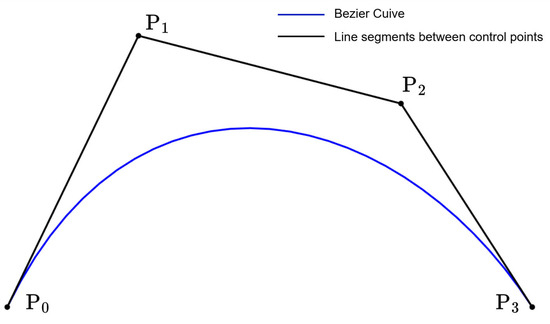
Figure 1.
The three-degree Bézier curve.
Note that the Bézier curve always passes through two end control points; hence, it is easy to meet boundary constraints when using it to represent the interceptor trajectory. By adjusting the interior control points, the shape of the Bézier curve can be altered to obtain the optimal trajectory under all other constraints.
3.2. Trajectory Optimization Method for Single Interceptor
3.2.1. Problem Representation Based on the Bézier Curve
By using the Bézier curve to represent the interceptor trajectory, problem P1 can be transformed into a parameter optimization problem for the Bézier curve. The Bézier curve directly parameterizes the position . To retrieve the corresponding velocity v and angles from the position derivatives, we inversely solve the first three subequations in the dynamic model Equation (1),
Furthermore, the derivatives of v, and are
Control variables can be calculated by inversely solving the last two equations in the dynamic model Equations (1)–(3),
Different from Ref. [29], the interceptor glides in the midcourse guidance phase and it has no thrust. The fourth subequation (i.e., the velocity differential equation) in the dynamic model Equation (1) is not actively used in the control variable calculation. To ensure that the optimized trajectory remains dynamically consistent with this unpowered flight condition, this equation is enforced as a path constraint,
where is a very small positive real number.
To solve using the Bézier curve, the flight time needs to be converted to the dimensionless factor , where . Thus, the boundary conditions are
where the superscripts and represent the derivatives of the dimensionless time parameter and the flight time t, respectively.
The three-dimensional position coordinates of the interceptor can be expressed as the following Bézier curve functions:
where are the degrees of the Bézier functions, are the Bernstein basis functions, and are the control points. Once are obtained, the Bézier functions are determined. Thus, are the optimization variables in this paper. Taking the x-axis direction as an example, the Bernstein basis function is
The first two and the last two control points of the Bézier function can be obtained from Equation (25) as follows:
When the boundary conditions are given, the four control points of the Bézier function are determined, and the remaining control points are optimization variables. The same method is used in the y-axis and z-axis directions. Then, there are optimization variables for , where , , . In addition, the optimization variables also include the terminal velocity , the terminal trajectory inclination angle , and the terminal trajectory deviation angle .
In summary, there are in total optimization variables using the Bézier curve. According to Equations (15)–(17), we can use Bézier functions to describe to represent the other state variables and the control variables and , and make them satisfy the constraints Equations (7)–(10) and (18). Finally, the fixed-time trajectory optimization problem for a single interceptor is transformed into the following parameter optimization problem:
3.2.2. Discretization
Problem is a continuous (infinite-dimensional) optimization problem. By selecting K discrete points on the interceptor trajectory, expressing all control and state variables in discrete form, and making the constraints in valid at these K discrete points, it can be transformed into a finite-dimensional optimization problem. In this paper, the roots of the K-degree Legendre polynomial are employed to discretize the dimensionless factor ,
Taking the x-axis direction as an example, represents all the control points of the Bézier function , i.e., . Then, the position coordinate x, the first-order derivative of x, and the second-order derivative of x at the K discrete points are expressed as follows:
where is the weight matrix of all control points. Substituting into Equation (21) yields
When the degree of the Bézier function and the number of discrete points K are selected, , , and will be constant matrices. The same method is used in the y-axis and z-axis directions. Then, the discretized forms of all state variables and their first-order derivatives, i.e., , , , , and can be represented by substituting Equation (29) into Equations (15) and (16). The discretized forms of all control variables, i.e., and , can be represented by substituting Equation (29) into Equation (17). Finally, the problem is expressed as the finite-dimensional discretized form.
3.2.3. Initial Guesses of Optimization Variables
To solve the discretized form of problem , it is necessary to provide suitable initial guesses for all optimization variables. An initial guess method for the Bézier curve parameters , is provided in this paper.
In general, the degree of the Bézier curve must be greater than 3 to estimate the interceptor trajectory. Here, the interceptor three-dimensional position coordinates are all assumed to be three-degree Bézier curves,
where the values of all control points in Equation (31) can be obtained by Equation (26),
In subsequent optimization, the degree of the Bézier curve is generally greater than 3. By substituting Equation (31) into Equation (29), the initial guesses of the Bézier curve parameters can be obtained as follows:
Then, the problem can be solved by a standard nonlinear programming (NLP) solver.
In summary, the process of solving the interceptor trajectory optimization problem based on the Bézier curve is shown in Figure 2.
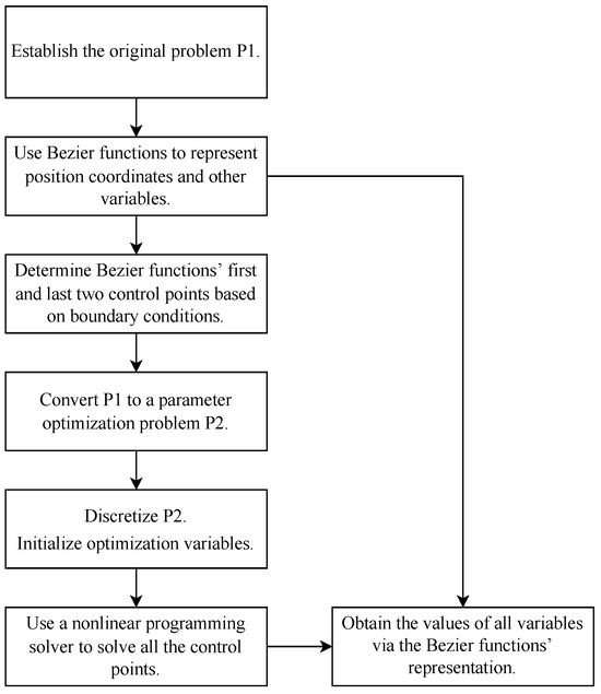
Figure 2.
Flowchart of interceptor trajectory optimization based on Bézier curve.
4. Numerical Examples
The initial position, velocity, trajectory inclination angle, and trajectory deviation angle of the interceptor are listed in Table 1. All simulations are performed on a personal computer with Intel Core i5-12600KF 3.70 GHz processor (Intel Corporation, Santa Clara, CA, USA) and 32 GB of DDR4 RAM, and executed via MATLAB 2023b software.

Table 1.
Parameter values.
The target’s position, the maximum angle of attack, overload, dynamic pressure, and heat rate for the interceptor are also listed in Table 1. The interception time is set as 130 s. The positive parameter in is set as 0.01.
4.1. The Effects of Number of Discrete Points and Degree of Bézier Functions
The proposed Bézier curve-based trajectory optimization method is related to the number of discrete points and the degree of Bézier functions. For different numbers of discrete points (N) and degrees of Bézier functions () in the proposed method, the computation time and the performance index are plotted in Figure 3 and Figure 4, respectively. Generally speaking, as the number of discrete points and the degree of Bézier functions increase, both the performance index and the calculation time increase. A trade-off is required between the performance index and the computation time. When and , the computation time exceeds 0.6 s. When or , the performance index is less than 2175 m/s. When , the calculation time is 0.35 s, and the performance index is 2184.6 m/s, reaching 98.27% of the optimal solution in Figure 4. Then, the following simulations are all performed with .
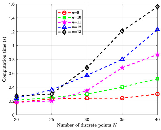
Figure 3.
Computation times for different N and n.
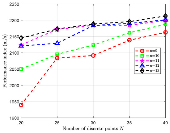
Figure 4.
Performance indices for different N and n.
It should be notified that a higher Bézier curve degree n provides greater flexibility to match the dynamics, reducing the error in the dynamic equations when the path is discretized. The number of discrete points N determines how rigorously the path constraints are enforced. The selection of and ensures that the transcribed problem provides an accurate representation of the continuous-time optimal control problem, as demonstrated by the feasible and smooth trajectories generated in all 100 simulations in Section 4.2. Beyond these values, the improvement in dynamic fidelity becomes negligible relative to the increase in computation time.
When , as shown in the three-dimensional trajectory of the interceptor plotted in Figure 5. The velocity curve is plotted in Figure 6. The curves of the angle of attack, the overload, the dynamic pressure and the heat rate are plotted in Figure 7, which indicates that the angle of attack, the overload, the dynamic pressure, and the heat rate are all within the given constraints. The bank angle curve is plotted in Figure 8.
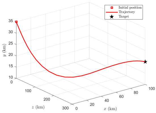
Figure 5.
Three-dimensional trajectory.
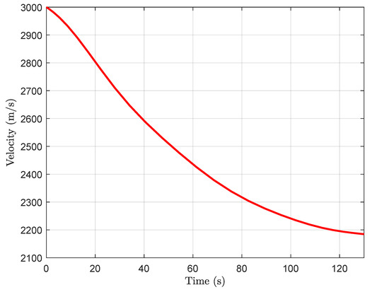
Figure 6.
The velocity curve.
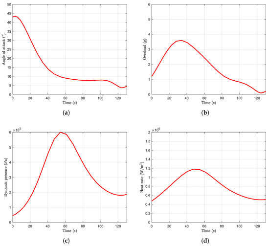
Figure 7.
The path constraint curves: (a) angle of attack; (b) overload; (c) dynamic pressure; (d) heat rate.
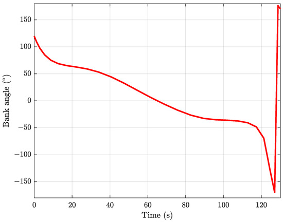
Figure 8.
The bank angle curve.
4.2. Comparison with Traditional Methods
To verify the superiority of the proposed Bézier curve-based method, three traditional methods, including the GPM, the SCP, and the IDVD method, are used to solve the single-interceptor trajectory optimization problem. For comparison, all methods employ the same discretization scheme using 30 Legendre–Gauss (LG) points. The “fmincon” function with the sequential quadratic programming (SQP) algorithm is used in the proposed method and the GPM, while the MOSEK solver is used in the SCP. Both the GPM and the SCP start from random initial guesses. Each state variable is randomly chosen between the initial and terminal values; the angle of attack is randomly chosen between 0 and the maximum value, the bank angle is randomly chosen between −180° and 180°, and all these values obey uniform distribution. A total of 100 tests are performed to minimize stochastic effects. The three-dimensional trajectories of all four methods are plotted in Figure 9.
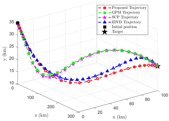
Figure 9.
Three-dimensional trajectories of the four methods.
(1) Compared with the GPM
The comparison results of the proposed method and the GPM with random initial guess are listed in Table 2. The following relative performance is quantified by the percentage difference, calculated as . Under this metric, compared with the GPM, the proposed method can achieve 95.61% of the average performance index, but it takes only 7.28% of the average computation time. It is noted that the performance index plateaus after 0.35 s because the Bézier curve parameterization introduces a modeling approximation to achieve fast computation speed, which prevents it from reaching the optimal solution found by the GPM. So the proposed Bézier curve-based method can be used as an initial guess for the GPM. The results in Table 3 show that the GPM with the proposed Bézier initial guess can reduce computation time by 73.39%. Thus, the result of the proposed method can be used as a fast solution satisfying all the boundary constraints and the path constraints, and it can also be used as an initial guess for further optimizations.

Table 2.
Result comparison of the proposed method and the GPM with random initial guess.

Table 3.
Result comparison of the GPM with random initial guess and Bézier initial guess.
To verify the proposed method for different interception times, the proposed Bézier curve-based method and the GPM (with Bézier initial guess) are used for four interception times , and the results are listed in Table 4. Compared with the GPM for different interception times, the proposed method can achieve at least 94.90% of the average performance index, but it takes at most 27.34% of the average computation time.

Table 4.
Comparison between the proposed method and the GPM for different interception times.
(2) Compared with the SCP
The comparison results of the proposed method and the SCP with random initial guess are listed in Table 5. Compared with the SCP, the proposed method can achieve 95.24% of the average performance index, but it takes only 2.16% of the average computation time. Moreover, the proposed Bézier curve-based method can also be used as an initial guess for the SCP.

Table 5.
Result comparison of the proposed method and the SCP with random initial guess.
The proposed method achieves significant computational advantages because of the difference in problem size. The Bézier curve-based method transforms the original problem into a low-dimensional optimization of a few control points, i.e., optimization variables in total as mentioned in Equation (27). For , the proposed Bézier curve-based method has a total of 27 optimization variables. For the SCP and the GPM, the number of optimization variables is the product of the number of discrete points and the number of state and control variables. Note that there are eight state and control variables (i.e., ) and discrete points, the GPM and the SCP have a total of optimization variables, which is much larger than the number of optimization variables in the proposed method.
(3) Compared with the IDVD method
The IDVD method needs to guess the virtual factor [25], which will affect the performance index and the computation time. To minimize stochastic effects, 100 numerical tests with random guess are executed and the results are listed in Table 6. The average performance indices by the proposed method and the IDVD method are almost the same. However, the proposed method take only can 16.51% of the average computation time of the IDVD method. For the IDVD method, although the minimum computation time is short, the computation time may be excessive, and even the IDVD method does not converge for an inaccurate guess value. Thus, the proposed method is more stable than the IDVD method.

Table 6.
Result comparison of the proposed method and the IDVD method.
5. Conclusions
This paper proposes a midcourse trajectory optimization method by representing the position coordinates of the interceptor with Bézier functions. By optimizing the control points of the Bézier functions, this method has the advantage of directly satisfying the boundary constraints and significantly speeding up the optimization process. By using the proposed Bézier curve-based method, the computation time is only 0.35 s, indicating that the trajectory optimization can be recalculated and updated almost in real time. For numerical experiment, the proposed method is compared with the GPM, the SCP, and the IDVD method. The numerical results show that the proposed method achieves a performance index of more than 95% compared to both the GPM and the SCP, but it takes less than 10% of the computation time required by the GPM and the SCP. Moreover, compared with the IDVD method, the proposed method achieves the same performance index, but it takes less than 20% of the average computation time and is more stable. The proposed method can be used as a fast solution satisfying all the boundary constraints and the path constraints, and it can also be used as an initial guess for further optimizations. The main limitation of this method is that the Bézier curve is continuously differentiable, which leads to poor approximation for non-smooth or discontinuous curves.
Author Contributions
Conceptualization, J.L. and G.Z.; methodology, J.L.; software, J.L.; formal analysis, J.L.; investigation, J.L.; data curation, J.L.; writing—original draft preparation, J.L.; writing—review and editing, J.L. and G.Z.; supervision, G.Z.; resources, L.C.; visualization, L.C. All authors have read and agreed to the published version of the manuscript.
Funding
This research received no external funding.
Informed Consent Statement
Informed consent was obtained from all subjects involved in the study.
Data Availability Statement
Data are contained within the article.
Conflicts of Interest
The authors declare no conflicts of interest.
List of Abbreviations and Symbols
The following abbreviations and main symbols are used in this manuscript:
| GPM | Gauss Pseudospectral Method |
| SCP | Sequential Convex Programming |
| SQP | Sequential Quadratic Programming |
| NLP | Nonlinear Programming |
| IDVD | Inverse Dynamics in the Virtual Domain |
| MPC | Model Predictive Control |
| FFS | Finite Fourier Series |
| LG | Legendre–Gauss |
| Position coordinates in ground launch frame | |
| v | Velocity of the interceptor |
| Trajectory inclination angle | |
| Trajectory deviation angle | |
| Angle of attack | |
| Bank angle | |
| g | Gravitational acceleration |
| m | Mass of the interceptor |
| L | Lift force |
| D | Drag force |
| S | Characteristic area of the interceptor |
| Lift coefficient | |
| Drag coefficient | |
| Air density | |
| Overloads in y-axis and z-axis directions | |
| q | Dynamic pressure |
| Q | Heat rate |
| T | Interception time/fixed flight time |
| Small positive real number for constraint tolerance | |
| t | Time variable |
| Dimensionless time parameter () | |
| P | Control points of Bézier curve |
| B | Bernstein basis function |
| Order/degree of Bézier curve | |
| Number of discrete points |
References
- Zhu, W.; Li, J.; Xu, Y. Optimum attitude planning of near-space solar powered airship. Aerosp. Sci. Technol. 2019, 84, 291–305. [Google Scholar] [CrossRef]
- Liu, X.; Li, X.; Zhang, H.; Huang, H.; Wu, Y. Entry Guidance for Hypersonic Glide Vehicles via Two-Phase hp-Adaptive Sequential Convex Programming. Aerospace 2025, 12, 539. [Google Scholar] [CrossRef]
- Liu, Y.; Chen, B.; Li, Y.; Shen, H. Overview of control-centric integrated design for hypersonic vehicles. Astrodynamics 2018, 2, 307–324. [Google Scholar] [CrossRef]
- Luo, C.; Zhou, C.; Li, J.; Lei, H. Trajectory optimization for high-speed and long-range interceptor based on improved adaptive hp pseudospectral method. Int. J. Aerosp. Eng. 2022, 2022, 7958272. [Google Scholar] [CrossRef]
- Zhang, H.; Tang, S.; Guo, J. Cooperative near-space interceptor mid-course guidance law with terminal handover constraints. Proc. Inst. Mech. Eng. Part G J. Aerosp. Eng. 2019, 233, 1960–1976. [Google Scholar] [CrossRef]
- Yang, B.; Jing, W.X.; Gao, C. Online midcourse guidance method for boost phase interception via adaptive convex programming. Aerosp. Sci. Technol. 2021, 118, 107037. [Google Scholar] [CrossRef]
- Zhang, P.; Cheng, L.; Gong, S. Fast trajectory replanning for cooperative vehicles using sequential convex programming. Astrodynamics 2025, 9, 369–388. [Google Scholar] [CrossRef]
- Li, W.; Li, J.; Li, N.; Shao, L.; Li, M. Online trajectory planning method for midcourse guidance phase based on deep reinforcement learning. Aerospace 2023, 10, 441. [Google Scholar] [CrossRef]
- Su, R.; Wang, J.; Zhang, S. Design of three-dimensional intelligent guidance law for intercepting highly maneuvering target. IEEE Access 2023, 11, 14274–14281. [Google Scholar] [CrossRef]
- Imado, F.; Kuroda, T.; Miwa, S. Optimal midcourse guidance for medium-range air-to-air missiles. J. Guid. Control Dyn. 1990, 13, 603–608. [Google Scholar] [CrossRef]
- Hughes, T.; McFarland, M. Integrated missile guidance law and autopilot design using linear optimal control. In Proceedings of the AIAA Guidance, Navigation, and Control Conference and Exhibit, Denver, CO, USA, 14–17 August 2000; AIAA: Reston, VA, USA, 2012. [Google Scholar] [CrossRef]
- Jeon, I.; Lee, J.; Tahk, M. Impact-time-control guidance law for anti-ship missiles. IEEE Trans. Control Syst. 2006, 14, 260–266. [Google Scholar] [CrossRef]
- Lee, J.; Jeon, I.; Tahk, M. Guidance law to control impact time and angle. IEEE Trans. Control Syst. 2007, 43, 301–310. [Google Scholar] [CrossRef]
- Harl, N.; Balakrishnan, S.N. Impact time and angle guidance with sliding mode control. IEEE Trans. Control Syst. 2011, 20, 1436–1449. [Google Scholar] [CrossRef]
- Cho, D.; Kim, H.; Tahk, M. Nonsingular sliding mode guidance for impact time control. J. Guid. Control Dyn. 2016, 39, 61–68. [Google Scholar] [CrossRef]
- Chen, X.; Wang, J. Nonsingular sliding-mode control for field-of-view constrained impact time guidance. J. Guid. Control Dyn. 2018, 41, 1214–1222. [Google Scholar] [CrossRef]
- Zhang, J.; Li, J.; Zhou, C.; Lei, H.; Li, W. Fast trajectory generation method for midcourse guidance based on convex optimization. Int. J. Aerosp. Eng. 2022, 2022, 7188718. [Google Scholar] [CrossRef]
- Zhou, C.; He, L.; Yan, X.; Meng, F.; Li, C. Active-set pseudospectral model predictive static programming for midcourse guidance. Aerosp. Sci. Technol. 2023, 134, 108137. [Google Scholar] [CrossRef]
- Jin, Z.; Lei, S.; Huaji, W.; Dayuan, Z.; Humin, L. Optimal midcourse trajectory planning considering the capture region. JOurnal Syst. Eng. Electron. 2018, 29, 587–600. [Google Scholar] [CrossRef]
- Bernardini, N.; Baresi, N.; Armellin, R. State-dependent trust region for successive convex programming for autonomous spacecraft. Astrodynamics 2024, 8, 553–575. [Google Scholar] [CrossRef]
- Li, D.; Li, Y.; Liu, X.; Yang, B.; Huang, X.; Yang, Y.; Wang, B.; Li, S. Pseudospectral convex programming for free-floating space manipulator path planning. Space Sci. Technol. 2023, 3, 0030. [Google Scholar] [CrossRef]
- Bai, S.; Chen, H.; Zhang, S.; Geng, C.; Han, C.; Xu, M. Exoatmospheric intercept guidance based on relative-motion control with respect to zero-effort orbit. Space Sci. Technol. 2024, 4, 0112. [Google Scholar] [CrossRef]
- Ottesen, D.; Russell, R. Direct-to-indirect mapping for optimal low-thrust trajectories. Astrodynamics 2024, 8, 27–46. [Google Scholar] [CrossRef]
- Yakimenko, O. Direct method for rapid prototyping of near-optimal aircraft trajectories. J. Guid. Control Dyn. 2000, 23, 865–875. [Google Scholar] [CrossRef]
- Li, W.; Li, J.; Li, M. On-line rapid planning method for interceptor missile midcourse guidance trajectory. Acta Armamentarii 2021, 42, 2617–2625. (In Chinese) [Google Scholar]
- Huo, M.; Zhang, G.; Qi, N.; Liu, Y.; Shi, X. Initial trajectory design of electric solar wind sail based on finite Fourier series shape-based method. IEEE Trans. Aerosp. Electron. Syst. 2019, 55, 3674–5683. [Google Scholar] [CrossRef]
- Fan, Z.; Huo, M.; Qi, N.; Zhao, C.; Yu, Z.; Lin, T. Initial design of low-thrust trajectories based on the Bezier curve-based shaping approach. Proc. Inst. Mech. Eng. Part G J. Aerosp. Eng. 2020, 234, 1825–1835. [Google Scholar] [CrossRef]
- Sun, K.; Han, S.; Niu, F.; Yu, R.; Ni, W.; Wang, Y. Fast attitude trajectory planning of spacecraft based on the Bezier shape-based method. In Proceedings of the 6th IEEE International Conference on Unmanned Systems, Hefei, China, 13–15 October 2023; IEEE: Piscataway, NJ, USA, 2023. [Google Scholar] [CrossRef]
- Yu, Z.; Qi, N.; Huo, M.; Fan, Z.; Yao, W. Fast cooperative trajectory generation of unmanned aerial vehicles using a Bezier curve-based shaping method. IEEE Access 2022, 10, 1626–1636. [Google Scholar] [CrossRef]
- Rizvi, S.; He, L.; Xu, D. Optimal trajectory analysis of hypersonic boost-glide waverider with heat load constraint. Aircr. Eng. Aerosp. Technol. 2015, 87, 67–78. [Google Scholar] [CrossRef]
- Li, H.; He, S.; Wang, J.; Shin, H.S.; Tsourdos, A. Near-optimal midcourse guidance for velocity maximization with constrained arrival angle. J. Guid. Control Dyn. 2021, 44, 172–180. [Google Scholar] [CrossRef]
Disclaimer/Publisher’s Note: The statements, opinions and data contained in all publications are solely those of the individual author(s) and contributor(s) and not of MDPI and/or the editor(s). MDPI and/or the editor(s) disclaim responsibility for any injury to people or property resulting from any ideas, methods, instructions or products referred to in the content. |
© 2025 by the authors. Licensee MDPI, Basel, Switzerland. This article is an open access article distributed under the terms and conditions of the Creative Commons Attribution (CC BY) license (https://creativecommons.org/licenses/by/4.0/).