Abstract
In this paper, a full-domain stochastic response analysis is performed based on the meshless method to reveal the time–frequency dynamic characteristics, including the power spectral density (PSD) responses in the frequency domain and the evolving PSD distribution in the time domain for a sandwich trapezoidal plate–shell coupled system. The general governing equations are derived based on the first-order shear deformation theory (FSDT), linear piston theory and Hamilton’s principle, and the stochastic excitation is integrated into the meshless framework based on the pseudo-excitation method (PEM). By constructing the meshless shape function covering the entire structural domain from Chebyshev polynomials and discretizing the continuous domain into a series of nodes within a square definition domain, the points are assembled according to the sequence number and the equilibrium relationship on the coupling edge to obtain the overall vibration equations. The validity is demonstrated by matching the mode shapes, PSD responses, time history displacement and critical flutter boundaries with FEM simulation and reported data. Finally, the time–frequency characteristics of each substructure under global and single stochastic excitation, and the effect of aerodynamic pressure on full-domain stochastic vibration, are revealed.
1. Introduction
The plate–shell coupling structure is a common prototype in the design of high-speed aerospace vehicles [1,2,3,4,5,6], consisting of a pair of symmetrical quadrilateral subplates to constitute the wing surfaces and a subshell to assemble the fuselage. With the rapid development of new materials and the continuous lightweighting of structural design, the velocity of aircraft must be further improved to meet the rapid iteration requirements of engineering. Therefore, the aerodynamic load caused by supersonic airflow will not only lead to flutter of thin-walled surfaces when a certain level is reached, but will also further amplify the dynamic instability of the structure if it is subjected to any other external excitation [7], especially stochastic vibration behavior under harsh working conditions. The stochastic loads can be generally classified as base acceleration excitation in the frequency domain and random forces in the time domain with uncertain amplitude [8,9,10,11,12]. Since a subplate and a subshell may exhibit different time–frequency characteristics in the face of stochastic excitation [13], it is necessary to conduct a full-domain stochastic dynamic analysis for a plate–shell coupled structure and consider the problem of fluid–structure interaction [14,15] to investigate the comprehensive time–frequency characteristics in supersonic airflow. Also, a basis for the subsequent study of precise coupling models and any random vibration response is provided.
In order to investigate the dynamic characteristics of the coupled structures subjected to various types of excitation, many researchers have proposed comprehensive coupling schemes for the establishment of mathematical models. Taking the analytical technique as an example, some researchers have developed the wave-based method to construct dynamic models between multiple substructures [13,16,17,18,19], which derive the scattering matrix based on the generalized displacements and generalized forces at each connection of multiple substructures, thereby assembling the overall system equation to be solved. Although the analytical model can provide solutions with more accuracy and has great advantages in solving the frequency response of the system, it often imposes certain restrictions on the boundary conditions of the structure. Also, the phase relationship established based on the nodes makes it only suitable for analyzing regular structures. In order to remove the limitations of analytical methods on boundary conditions and arbitrary shapes, many researchers have also developed semi-analytical meshless methods to discretize the irregular physical domain into a series of nodes from the energy functionals [20,21,22,23,24]. Through employing a coordinate mapping technique, it is converted into a square plate on the natural domain to establish the vibration equations. Meanwhile, the connection of coupling between each substructure can be achieved by constructing the equilibrium relationship at edge nodes and replacing the original stiffness matrix [25,26,27,28]. In the existing literature, the development of such a meshless method primarily covers the mode shapes, random vibration in the frequency domain and independent study on aeroelasticity for irregular or coupled structures. Studies on the comprehensive analysis of the stochastic dynamic characteristics in the frequency and time domain for a plate–shell coupled structure in supersonic airflow have not yet been reported.
To efficiently solve the stochastic dynamic characteristics of the structure, Lin et al. [29] proposed the pseudo-excitation method (PEM) to convert any problem of stationary/non-stationary stochastic vibration into a simple harmonic vibration and time history response analysis, which greatly improved the computational efficiency over the traditional methods. In recent years, many researchers have conducted many excellent studies on the stochastic vibration of plate and shell structures based on the PEM. Zhou et al. [30] investigated the stationary and nonstationary stochastic responses of composite laminated plates on the displacement field of the modified Fourier series and the PEM. Zhong et al. [31] studied the power spectrum density (PSD) responses of quadrilateral plates and folded plates subjected to base acceleration excitation through the PEM and the meshless method. Huo et al. [32] proposed the combination of the discrete analytical method (DAM) with the PEM to investigate the stationary/non-stationary stochastic response for an orthotropic cylindrical shell. Shi et al. [33] used the spectro-geometric method to establish a stochastic dynamic model of a closed rocket shell system under base acceleration excitation. Chen et al. [34] combined the PEM with the precise integration method (PIM) to achieve an efficient solution to the nonstationary responses of thin plates under moving random loads. In a supersonic environment, Shi et al. [35] studied the frequency-domain stochastic responses of FGM slantingly coupled plates based on the meshless method, which reveals the effect of aerodynamic pressure on the dynamic performances. From the present reported literature, it can be found that the focus on stochastic response in the time domain is reflected in the single structure of plate or shell. However, an investigation into any plate–plate or plate–shell coupled structures is concentrated on the base acceleration excitation in the frequency domain, which leads to a lack of revelation of the time–frequency characteristics of the aircraft surface, especially when the aerodynamic pressure is considered.
By reviewing the studies of the dynamic performance of plate and shell structures in supersonic airflow, it can be known that the linear and nonlinear piston theories are common methods for predicting the aerodynamic pressure under different Mach number conditions. Under the assumption of linear piston theory, Li et al. [36] analyzed the aerothermoelastic of the composite laminated plates by employing the linear piston theory to compute the unsteady aerodynamic force, and proposed a method of suppressing flutter and thermal buckling. Chai et al. [37] studied the thermal flutter and buckling characteristics of lattice sandwich plates on an elastic foundation based on the linear piston theory, and the effects of a series of geometric parameters on the dynamic behavior with aerothermoelastic coupling are investigated. Singha and Mandal [38] used the linear piston theory to evaluate aerodynamic pressure to study the flutter behavior of a cylindrical panel. Pany and Parthan [39] studied the one-dimensional axial wave propagation problem of a periodically supported cylindrical curved panel under supersonic airflow, in which the aerodynamic force is calculated based on the linear piston theory. Muc and Flis [40] discussed the optimization design problem of multi-layer composite cylindrical panels under free vibration and supersonic flutter constraints. Bochkarev [41] studied the aeroelastic problem of stiffened shallow shells and investigated the parameters that can improve the critical flutter boundary. Meanwhile, Lin et al. [42] proposed a solution to the aeroelasticity of FG-CNT reinforced composite plates based on the third-order piston theory, the effect of oblique shock waves on the critical flutter boundary and the time history response are investigated. Asadi and Beheshti [43] gave the aeroelastic dynamic model of the FG-CNT composite beam, the effects of material and geometric parameters are revealed. It can be determined from the literature that for most thin-walled structures with a velocity between Mach √2 to 5, the introduction of the linear piston theory is reasonable and efficient.
After evaluating the existing research and identifying the gap in the full-domain stochastic vibration characteristics of plate–shell coupled structures in supersonic airflow, the primary content of this work are organized as follows: first, the cross-section is composed of C/SiC as the top and bottom surfaces and an orthotropic material as the core layer. The first-order shear deformation theory (FSDT) and linear piston theory are employed to derive the general governing equations with the coordinate boundary conditions, and the expressions of the full-domain stochastic excitation are given based on the PEM. Then, in order to obtain a shape function that covers the entire structure domain with a fast convergence, the continuous domains are discretized into a series of nodes by a node-based meshless method constructed from Chebyshev polynomials. Next, three verification cases of the trapezoidal plate–shell plate coupling system are given to ensure the correctness of the stochastic responses. Finally, a series of numerical analyses is proposed to discuss the PSD responses and evolving PSD distribution by adjusting comprehensive parameters in the system.
The practical application of this study lies in the rapid prediction of the full-domain stochastic dynamic characteristics for those prototypes of coupled plate–shell structures subjected to supersonic airflow. During the design optimization and demonstration phase for a high-speed aircraft, the advantages of this study are that a semi-analytical model is established by a strong-form meshless method, which has high coding efficiency, low computational resource consumption, and is convenient for parametric analysis. Therefore, this study enables rapid qualitative analysis of specified parameters. Meanwhile, it can accurately and quickly reflect the time–frequency dynamic characteristics of different types of substructures, thereby giving a preliminary prediction of those potentially sensitive areas on aircraft surfaces in engineering and providing guidance.
2. Theoretical Model of Plate–Shell Coupling System
A plate and shell with general boundaries on the plane are considered as the object in this section. Based on the FSDT and Hamilton’s principle, the displacement–strain field and the constitutive relationship for the composite section are established, and the governing equations with their coordinated boundary conditions are derived according to the strain, kinetic energy and external work of each substructure. Furthermore, a meshless technique based on the Chebyshev polynomials is used to discretize the subdomain, and the stiffness, mass and damping matrices of each node are assembled into the overall system equation.
2.1. Model Description
As shown in Figure 1, the coupled structure consisting of a trapezoidal plate–cylindrical panel–trapezoidal plate can be regarded as the wing or empennage of most aircraft. In order to simplify the description of the displacement–strain field for the plate–shell coupling, a cylindrical coordinate system suitable for the subshell is primarily used to present the subsequent derivation, and the subplate can be obtained by setting the curvature radius of the shell to infinity, thereby obtaining a unified displacement–strain relationship and governing equations. Here, θ, y and z represent the arc, axial and radial thickness directions for a shell with a radius of curvature R, respectively. To meet the requirements of a light weight, impact resistance and heat insulation, the cross-section of the structure is laid out by a sandwich scheme composed of two types of materials, in which the top and bottom layers are ceramic matrix composite materials of C/SiC and the core layer is a composite laminated orthotropic layer. Each boundary and coupling edge is supported and connected by artificial springs, and the external random loads of interest include base acceleration excitation in the frequency domain and distributed loads in the time domain.
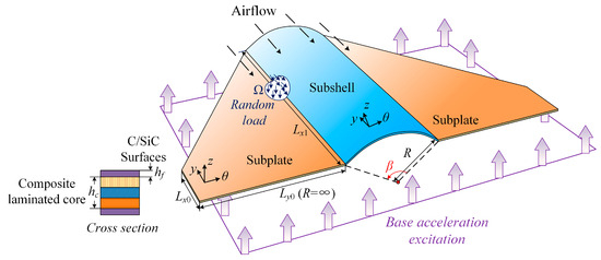
Figure 1.
Diagram of a trapezoidal plate–shell coupling structure subjected to stochastic load in supersonic airflow.
2.2. Governing Differential Equations for the Substructures
Many studies have shown that the FSDT has sufficient accuracy in predicting the deformation for those thin-walled or medium-thick structures [30,44,45]. Thus, the displacement field of any point on the mid-surface for the subplate and subshell in this study, where the thickness direction is much smaller than the length and width, can be written in the form of the FSDT as
where u0, v0, w0 are the displacement components along the entire trailing edge, the shell generatrix and the normal direction of any substructure, respectively. φθ and φy represent the rotation components along the y-axis and x-axis.
The strain field of the substructures can be expressed as
with the strain vector , which can be written in a matrix form as
where u = {u0, v0, w0, φθ, φy}T is the displacement vector, the matrix of partial differential operators can be expressed as
where A = B = R for the case of the subshell, and A = 1, B = ∞ for the case of the subplate.
Similarly to Equation (3), the integrated stress of any substructure in the thickness direction can be written in the corresponding form:
with the resultant stress is obtained by integrating the stress on each layer section along the entire thickness, which is defined by
where nc denotes the total number of layers; the laminated stiffness coefficients are collected in the matrix D as
with the shear correction factor κ = 5/6, the coefficients Aij, Bij, Dij are the laminated stiffness obtained by integrating the material properties through its thickness, which can be defined as
where Qij is the stiffness coefficient converted according to different types of material parameters, k represents the kth layer within the cross-section. For the two surface layers, it is given as
where Ef, μf, and represent the elastic modulus, Poisson’s ratio and shear modulus of the top and bottom layers composed of C/SiC. For the core layer composed of composite laminates, it is given by the angle ψk of fiber orientation in the kth layer in the matrix T as
with
where represent the elastic modulus, Poisson’s ratio and shear modulus of the orthotropic composite material constituting the core layer.
The governing equations and coordinate boundary conditions of the substructure are obtained by performing the Hamilton’s principle and integration by parts. First, the strain energy of any substructure can be expressed in its geometric domain Ω as
where A = 1 is for the case of the subplate and A = Rx is for the subshell. Then, the expression of kinetic energy is given as
where the moment of inertia I0, I1 and I2 should be superimposed according to the density of each layer ρk as
Next, the modal damping can be derived in the form of work performed by the damping force as
where c = 2ζω is the viscous damping coefficient determined by the system damping ratio ζ and the harmonic frequency ω.
The first-order linear piston theory is an effective and convenient method for predicting flutter characteristics in engineering. It applies to the conditions that the thickness of the panels is thin and they have a flight speed between Mach 2–5. The assumptions are based on small perturbations and the pressure at a point on the panel is primarily determined by the downwash velocity. In this case, the unsteady aerodynamic forces on the structure are determined by the normal velocity perturbations on the panel, and viscosity and boundary layer effects are often neglected in the current Mach range. The key parameters considered are the air density, velocity and Mach number at the vehicle’s location.
Generally, the aerodynamic load caused by the oncoming supersonic airflow based on the linear piston theory can be written as [38,41,46]
where ρair, U, M denote the air density, stream velocity and Mach number.
Finally, substituting the above energy expressions into Hamilton’s principle, the governing differential equations with the external excitation vector f = {fu, fv, fw, fθ, fy}T for any substructure can be obtained as
The coordinate boundary conditions at the four edges of the trapezoidal plate and the cylindrical panel are constructed by artificial springs:
where k is the stiffness value of the virtual springs.
Here, Equation (17) is simplified into matrix form according to the partial differential operator matrix L, resultant stresses N, damping matrix C, mass matrix M and external force load vector F to facilitate the subsequent meshless discretization as
For the transverse base acceleration excitation, the stochastic load in the subplate is expressed as the PSD of in the frequency domain based on the PEM:
and the load in the subshell can be decomposed into the excitation along the circumferential and radial direction according to the corresponding central angle β:
The spectral density in the frequency domain of the structural response can be further obtained from the virtual response as
where “*” represents the complex conjugate. Suu, Svv and Saa represent the displacement, velocity and acceleration PSD responses for the stochastic dynamic problem.
For the stochastic load in the time domain, which can be applied to any area of the structure in the form of a point, line or surface. Assuming that the self-spectral density of the load is Sθθ(ω), a virtual deterministic external excitation at (θ0, y0) can be constructed as
Similarly, the evolving spectral density of the structural response in the time domain can also be expressed by the virtual response as
2.3. Meshless Discretization and Coupling of Substructures
After establishing the governing equations for each substructure with general boundary conditions, it can be seen that the unknown vector u that satisfies Equations (17) and (18) is the key to solving the stochastic responses of the system. As the governing equations are valid in the entire continuous plane domain, an analytical method usually results in restricted boundary conditions or geometric shapes that cannot achieve the required coupled structure. In regard of this, a semi-analytical meshless method is employed to discretize the continuous geometric domain into a series of nodes, where the physical quantities of any point in the discrete domain can be approximated by spectral superposition of other surrounding nodes. Since the subplate and subshell considered in this study both contain four edges, a large support domain that encompasses all N nodes can be used to make all nodes inside be support points for each other:
where U is given as all displacement vectors on a single substructure:
and Φ = {Φ1, Φ2, …, ΦN} is the shape function that contains the weight of each discrete node. In this study, it is constructed based on Chebyshev polynomials as
where c(θ) = cos[jcos−1(θ)], c(y) = cos[jcos−1(y)] (where j is the order of the polynomial and j = 1, 2, …m).
The number of two-dimensional Chebyshev polynomials m × n is equal to the number N of meshless nodes of the discretized structure. In view of the polynomial defined in [−1, 1], each node on the physical substructure is required to be mapped to the corresponding square natural domain as shown in Figure 2. From Ref. [47], the mapped coordinates x(x, y) can be obtained by placing a shape function that is not zero at the selected node xi(xi, yi) as
where M0 and N0 are the orders of the mapping polynomials, and setting them to values equal to 1 or greater often satisfies the computational requirements for those structures with all straight edges. Then, the partial differential operator in the discretized governing equations and boundary conditions can be expressed as
with
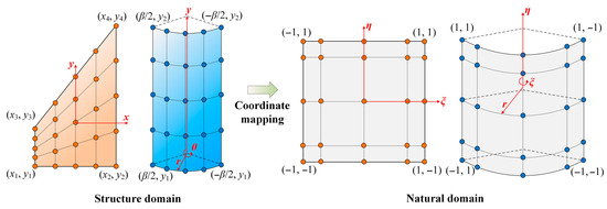
Figure 2.
Coordinate mapping of the subplate and subshell in the structure domain and the natural domain.
In addition, the partial derivatives computations for the shape function at different orders can be unified as
On this basis, the equilibrium relationship at any node xi on the substructure can be obtained by substituting Equation (25) into Equation (17) as
and the discrete stiffness matrix, damping matrix and mass matrix can be given as
where and the detailed expressions of the stiffness coefficients k11, k12, …, k55 in Equation (33) are given in the Appendix A. Therefore, by substituting Equation (31) into the partial differential operators defined in Equation (29) and then into Equation (A1), the stiffness coefficients for each discrete node can be obtained according to the arrangement of the shape functions Φi.
Assuming the system performs a simple harmonic vibration, this yields the general vibration equation as
Similarly, the equilibrium relationship at the boundaries pointed out in Equation (18) satisfies
where the extraction matrices cx, cy for the boundary stresses, and the stiffness matrices kx, ky for the boundary springs are given as
and the vibration equation on the edge nodes:
Therefore, the nodes within and at the edges of any substructure are required to satisfy Equations (36) and (40), which should be arranged in sequence and assembled into the overall vibration equation:
where the subscript “s” represents the serial number of a certain substructure.
Based on the current meshless technique, a coupled plate–shell system also requires the vibration equations to be linked together and the displacement equilibrium equations to be established at each coupling edge. Here, for an open shell with an arbitrary central angle β, the generatrix coupled with the trapezoidal plate at x = Lx yields the following equilibrium equation:
where kc denotes the coupling stiffness of the connection springs. Meanwhile, the coupling relationship on the other side of the subshell is
Equations (42) and (43) can be written in a matrix form:
where can be defined as the coupling matrices as
Similarly, the coupling matrices between substructures 2–3 can be obtained in the same way. Then, by combining Equations (40), (41) and (44), the system equation of the meshless coupled structure composed of a trapezoidal plate–open shell–trapezoidal plate can be assembled as follows:
with
Here, Equation (47) is written in the general form of the dynamic formulation for the total coupled structure to solve any dynamic characteristics:
In the frequency domain, the frequency response characteristics based on Equation (49) can be directly computed as follows:
In the time domain, the dynamic responses of the system can be computed with the help of the Newmark-beta technique. The initial displacement, velocity and acceleration of the system are all set to zero and they are iterated over a given time step. The displacement within a time step can be calculated in terms of the effective stiffness matrix and the force vector, which are defined as
with
and
Finally, the time history response of any point on the coupled plate–shell structure can be extracted from the matrix U.
3. Verification of Numerical Results
In this section, the effectiveness of the present meshless coupled composite plate–shell system subjected to stochastic excitation is primarily verified, including the natural frequencies with their modal shapes, and the stochastic responses in the time/frequency domains. In terms of the correctness of the coupling scheme for the laminated composite, the system frequencies ω solved by ignoring the external forces in Equation (47) should be compared first, which also provides a preliminary verification for the subsequent frequency responses.
The material and geometric parameters of the two subplates and subshells considered are given unless otherwise specified as
The surface layers of C/SiC are prepared by the chemical vapor infiltration (CVI) method and the mechanical moduli are collected as Ef = 152.37 GPa, μf = 0.25, ρf = 2003 kg/m3, G12 = 44.05 GPa, G13 = 24 GPa [48], hf = 0.001 m. The core layer of composite laminated: E1 = 175 GPa, E2 = 32 GPa, μ12 = 0.25, ρc = 1760 kg/m3, G12 = 12 GPa, G13 = 12 GPa, G23 = 5.7 GPa, hc = 0.003 m, the lamination scheme is given as [0°/90°/0°].
The geometric parameters for the trapezoidal subplates: Lx0 = 0.2 m, Lx1 = 1 m, Ly0 = 0.5 m. The geometric parameters for the subshell: β = 90°, Lθ0 = Lθ1 = 1 m, R = 0.25 m.
Here, a large spring stiffness value is used to indicate that the displacement degree of freedom is constrained. The stiffness matrices composed of the corresponding virtual springs for the clamped (C), simply supported (S) and free (F) boundaries are given as
- C: kθ = ky = diag{1015, 1015, 1015, 1015, 1015} N/m;
- S: kθ0 = kθ1 = diag{1015, 1015, 1015, 0, 1015} N/m, ky0 = ky1 = {1015, 1015, 1015, 1015, 0} N/m.
- F: kθ = ky = diag{0, 0, 0, 0, 0} N/m.
Then, the parameters related to the aerodynamic loads are given as ρair = 1.226 kg/m3, M = 5, and the velocity of the free stream U is the input variable.
Furthermore, the stochastic load in the time domain is treated as global excitation in each node if there is no additional explanation. In the subsequent verification cases and parameter analysis, the node configuration scheme based on the meshless technique is arranged as 15 × 15. The boundary conditions applied to the coupled structure are symmetrical, so the definition can be given in the order of left subplate and middle subshell. For example, SSC-CC means that the trailing edge and external edge on the subplate are S, while the front and back of the subshell are clamped. In Figure 3, the 2nd- to 10th-order mode shapes and the corresponding meshless frequency values under three types of boundary conditions are listed. It can be seen that the maximum error between the results from the FEM computation does not exceed 1%, and the mode shapes are also consistent with the simulation.
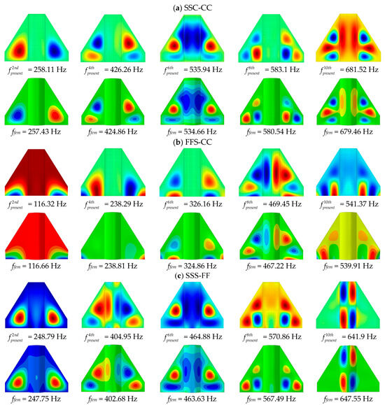
Figure 3.
Verification of natural frequencies with mode shapes of the meshless coupled plate–shell structure under different boundary conditions.
Next, for the cases of forced vibration, the stochastic responses under base acceleration excitation in the frequency domain and random load in the time domain will be verified. In order to simplify the verification process, the white noise excitation within 1–400 Hz with a PSD of 0.5 g2/Hz is selected to evaluate the displacement, velocity and acceleration PSD responses of the coupled structure, and the modal damping ratio of the system is given as ζ = 0.05. In Figure 4, the PSD responses of the center point of the subplate on the coupled structure with different core thicknesses are considered, which are in good agreement with the FEM results. Then, the analysis domain of forced vibration is converted to a random load in the time domain. Taking the same nodes as the observation point, Figure 5 collects the transient response in 0.02 s with different excitation frequencies when the modal damping is enabled, which is also consistent with the simulation results obtained by FEM software of Abaqus 2023.
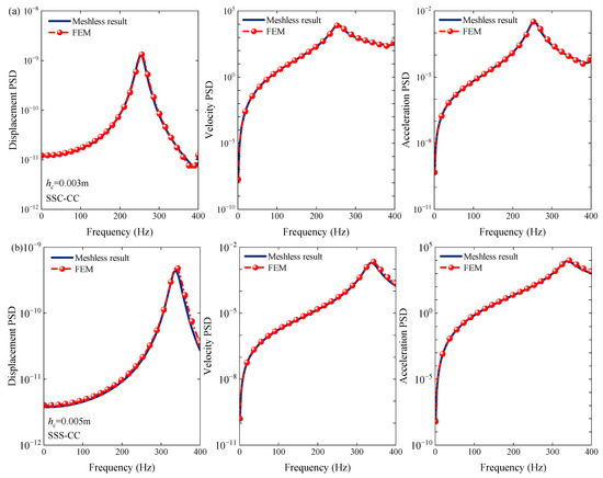
Figure 4.
PSD responses comparisons of plate–shell coupled structures with different core thickness under base acceleration excitation. (a) hc = 0.003 m; (b) hc = 0.005 m.
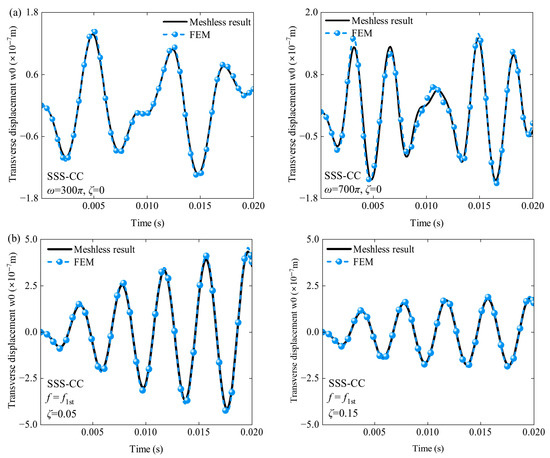
Figure 5.
Comparison of deterministic transient responses under external excitation in different harmonic frequencies: (a) transient responses with ignoring the damping effect; (b) transient responses with enabling the damping effect.
Finally, the meshless flutter boundary under supersonic airflow is compared with the published literature. The parameters of the case reproduced are given as a simply supported square plate with Lx = Ly = 0.305 m and h = 0.0013 m, and the material is also given as E = 68.9 GPa, μ = 0.3 and ρ = 2764 kg/m3 [36]. In addition, the dimensionless frequency are defined as , and the aerodynamic pressure in this study is defined as . The curves in Figure 6 show that the frequency variation and the critical flutter boundary under aerodynamic loads predicted in this study fit perfectly with the reported results, which proves the effectiveness of the aeroelastic model established by the meshless method.
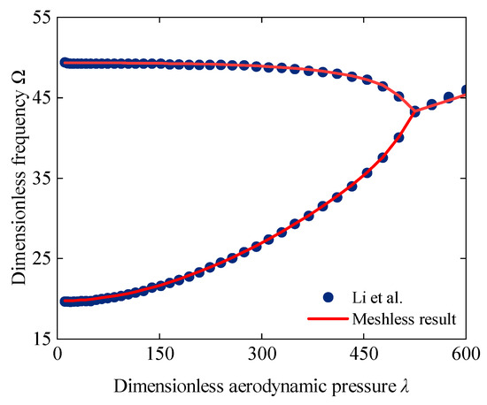
Figure 6.
Comparison of the first two frequency variations in a square plate subjected to aerodynamic loads with the published literature.
4. Parametric Cases and Discussion
After completing the verification of the global stochastic vibration response of the plate–shell coupled structure and the correctness of the meshless aeroelastic model in the present work, this section focuses on presenting a series of numerical cases to investigate the effects of geometric features and load parameters on the stochastic dynamic characteristics. For the PSD responses under base acceleration excitation in the frequency domain, the effects of geometric factors and aerodynamic loads are investigated, respectively. Meanwhile, the PSD distribution in a certain frequency band is considered to show the sensitive range in the time domain. Except for the specific geometric parameter variations investigated, the sizes of all plate–shell coupled structures are the same as those in Section 3.
4.1. Effect of Central Angle β on Frequency-Domain PSD Responses
The first case primarily examines the variations in PSD responses of the overall coupled structure when the central angle of the middle subshell is changed. In order to reduce the interference of the mass change caused by the angle on the results, the curvature radius Rx of the subshell is also changed synchronously to ensure that the circumferential length of the shell is constant. In Figure 7, the variations in displacement, velocity and acceleration PSD responses are shown as the central angle β increases from 22.5° to 180°, with the radius decreasing from 1 m to 0.25 m. The results show that the lower fundamental frequency of the shallower subshell leads to the first response peak appearing earlier than the other three cases, and the secondary peak is reflected in both velocity and acceleration PSD responses. Then, through the first peak corresponding to the given four angles, it can be found that the effect of the central angle β on the PSD of the subplate is significantly reflected between 22.5° to 90°, but the sensitivity decreases rapidly in the process of continuing to increase to a half shell. Meanwhile, by contrasting the responses at the center of the subshell in Figure 7b, it can be seen that the folating range of the response in the subshell is larger than that of the subplate, and the sensitivity of the PSD responses on the subshell to the angle β is more uniform over the entire range.
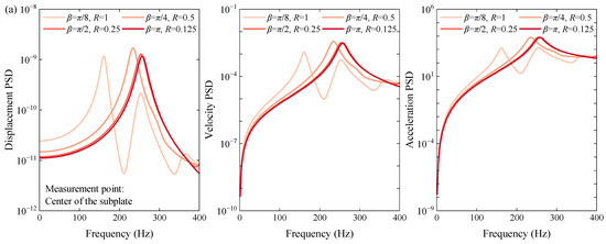
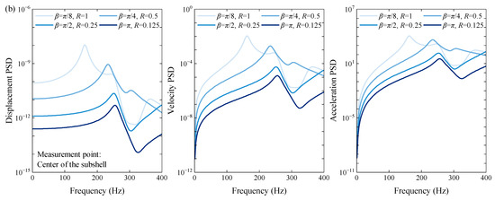
Figure 7.
Variations in PSD responses under different central angles β. (a) The PSD responses at the center of the subplate; (b) the PSD responses at the center of the subshell.
As can be seen, the modal distribution on the subshell becomes more concentrated as the curvature of the subshell increases, and the distribution of the natural frequency also tends to stabilize, resulting in a decrease in the sensitivity of the PSD response peak of the system to the angle β. The results indicate that for those aircraft designs involving coupling between a subplate and subshell, a small angle change in the subshell can lead to significant variations in dynamic response, necessitating more precise control of geometric parameters to avoid large amplitude fluctuations to ensure reliability and safety. The large center angles of the subshell produce relatively stable PSD responses, which makes them suitable for applications requiring higher dynamic stability.
4.2. Effect of Aerodynamic Loads on Frequency-Domain PSD Responses
Then, the effect of different aerodynamic loads on the PSD responses of the plate–shell coupled structure subjected to base acceleration excitation is considered. Since it is meaningless to present the frequency response when the flutter has already occurred, four dimensionless aerodynamic pressures before the critical flutter boundary are introduced, and the modal damping is ignored to highlight the response peaks. The frequency band of the excitation of 1–500 Hz is given to completely cover the first five-order natural frequencies of the system, which are 255.1 Hz, 256.3 Hz, 410.7 Hz, 423.3 Hz and 487.1 Hz. Here, the fact that the two adjacent frequencies are close to each other can be explained by the symmetry of the two subplates of the coupled structure. Meanwhile, the natural frequencies of the system under aerodynamic loads shown in Figure 8 make it clear that the flutter occurs at the first- and fourth- order and second- and third-order frequencies. However, regardless of the PSD responses at the center of the subplate and subshell in Figure 9, the peak will appear at the first- and third-order natural frequencies when the aerodynamic pressure is low. As the aerodynamic pressure increases, the response peaks corresponding to the second- and fourth-order frequencies can also be observed on the PSD curves, which excite all four natural frequencies in the given band. This phenomenon indicates that more severe aerodynamic loads will not only cause aeroelastic instability of the structure, but the system will also be more likely to resonate with more external harmonic excitations in this state.
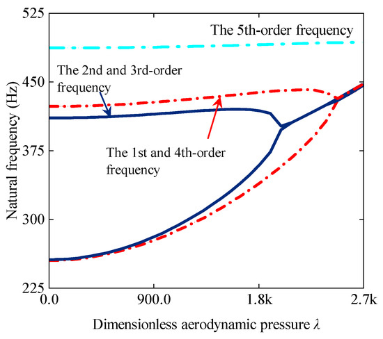
Figure 8.
Variations in the first five-order natural frequencies under aerodynamic pressure.
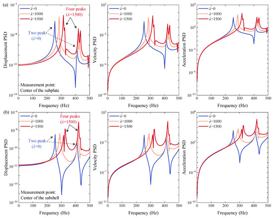
Figure 9.
Variations in the PSD responses under different aerodynamic pressure λ. (a) The PSD responses at the center of the subplate; (b) the PSD responses at the center of the subshell.
The above numerical results show that larger aerodynamic pressure reduces the stability margin of the system in higher-order frequency excitation and increases the possibility of resonance with external harmonics. Therefore, a layered suppression strategy should be adopted for different aerodynamic levels. For example, broadband damping can be used for optimization or active control at higher aerodynamic pressures, with special attention also paid to those adjacent modes.
4.3. Time–Frequency Analysis Based on the Evolving PSD
In the following subsections, the time–frequency characteristics of the structure under time-domain stochastic load in the same frequency band are investigated. In order to avoid special results and restore the actual loading conditions as much as possible, the excitation area covers every point on the plate–shell coupled structure. In the current case, the modal damping is re-enabled to compare the evolving PSD distribution on each substructure horizontally. By longitudinally comparing the responses at the center of the subplate and subshell in Figure 10 first, it can be clearly seen that the response amplitude on the subshell is weaker than that on the subplate, and the evolving PSD presented by the two types of substructures is different within the excitation band covering the first three fundamental frequencies of the system. On the subplate shown in Figure 10a, the resonance region of the evolving PSD is only concentrated near the first-order frequency of the system, and there are no other secondary peaks that can be observed in the rest of the frequency band. However, more PSD resonance peaks at each order frequency can be observed on the subshell, and the amplitude without a damping effect at the third order frequency is more prominent. Combined with the inherent properties of the system, this phenomenon can be attributed to the fact that the mode shapes corresponding to the first to second natural frequencies are mainly reflected on the subplate, while the third frequency is reflected on the subshell. Even so, it can be found that the subshell subjected to stochastic excitation is more prone to resonance in the time domain, which is more sensitive than the subplate.
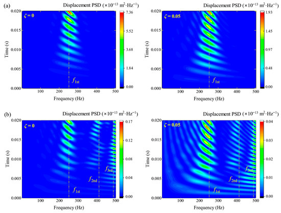
Figure 10.
The evolving PSD responses on different substructures when the modal damping is enabled. (a) The center of the subplate; (b) the center of the subshell.
Since the first few mode shapes of the coupled structure are generally reflected solely on the subplate or subshell, it can be inferred that there will be different characteristics in the face of modal damping when each substructure is subjected to random loads alone. By assuming that the stochastic load acts only on the two subplates or the subshell, the results in Figure 11 indicate that no matter whether the frequency of the load is at the first-order or the second-order frequency, the damping effect with different modal damping ratios weakens the response on the subplate uniformly. However, it will only take effect on the subshell when the excitation reaches a frequency close to the second frequency. Recalling the attenuation of the modal damping on the evolving PSD of each substructure at the first frequency in Figure 10, the peaks on the subplate and subshell are reduced by 73.8% and 66.7%, respectively. This phenomenon shows that the subshell has a higher resistance to modal damping than the subplate when it is loaded alone, but the addition of the coupled and loaded subplate will neutralize the resistance to a certain extent.
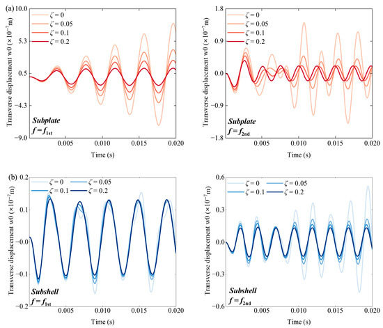
Figure 11.
Time history responses of a separately excited substructure at different damping ratios under the first–second frequency excitation of the system. (a) The responses on the subplate; (b) the responses on the subshell.
It is worth noting that the peak of the evolving PSD will also shift when the stochastic excitation acts only on any substructure of the coupled structure. In Figure 12, it can be seen that the resonance peak of each measurement point is reflected at the first frequency of the coupled structure as 255 Hz if only the two subplates are loaded. On the other hand, if only the subshell is loaded, the resonance peak of each measurement point is significantly shifted to the fifth frequency of 487 Hz. Since the primary mode shapes of the first and fifth natural frequencies of the system appear on the subplate and subshell alone, it can be inferred that the resonance band of the structure subjected to stochastic load will move with the change in the loaded area. However, the response peak under global excitation at all points in Figure 8 is still presented at the first frequency due to the larger proportion of the subplates; therefore, the complex loaded conditions should be evaluated in combination with the mode shapes and the weight of the excitation area.
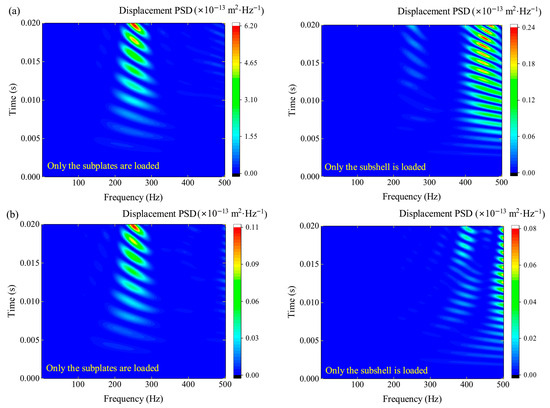
Figure 12.
The evolving PSD of a separately excited substructure at different measurement points. (a) The center of the subplate; (b) the center of the subshell.
4.4. Study on the Effect of Aerodynamic Loads on Evolving PSD
In the final numerical case, two aerodynamic pressures λ = 400 and λ = 1500 before the critical flutter boundary are selected according to Figure 8 to evaluate the variations in evolving PSD within the frequency band. In Figure 13, different from the response under stochastic load in the frequency domain, the peak of the subplate in the time domain is still reflected at the first frequency of the system when the aerodynamic effect is considered, and there are no response peaks that can be seen at the higher-order frequencies. As the aerodynamic pressure increases, the increase in the first frequency of the plate–shell coupling system results in the resonance band moving to the right. However, the subshell is still more likely to highlight the peaks corresponding to all the first five frequencies of the system under higher aerodynamic pressure. This phenomenon illustrates that when the aerodynamic and global time-domain stochastic excitation acts on the system simultaneously, the resonance bandwidth on the subshell is wider and more protective measures are required.
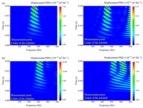
Figure 13.
The evolving PSD responses on different substructures under aerodynamic pressures. (a) Aerodynamic pressure λ = 400; (b) aerodynamic pressure λ = 1500.
Regarding the effect of aerodynamic loads on the evolving PSD distribution, the subplate exhibits a fundamental frequency-dominated, concentrated resonant response under higher aerodynamic pressure. Therefore, it allows for better targeted protection of the aircraft wing under harmonic excitation. However, the subshell still exhibits multimodal resonances and a wide frequency band under higher aerodynamic pressure, necessitating the use of damped connections and reinforced layouts to suppress potential broadband vibrations on the shell surface.
5. Conclusions
This work investigates the stochastic dynamic characteristics of a trapezoidal plate–shell–trapezoidal plate coupled system in supersonic airflow based on a node-based meshless method, in which the objective is to perform a time–frequency dynamic analysis for a high-speed vehicle prototype for design prediction. The numerical cases not only reveal the effect of aerodynamic loads on the PSD responses and evolving PSD distribution, but also highlight the differences in results and associated sensitivity analysis for different types of substructures. First, the governing equations with coordinate boundary conditions under stochastic excitation and aerodynamic pressure are derived based on the FSDT and Hamilton’s principle, and the coupling model is established with the help of a meshless node-based discretization technique of Chebyshev polynomials. Then, by matching the PSD responses under the base acceleration excitation in the frequency domain, the deterministic time history transient response in the time domain, and the critical flutter boundary under the aerodynamic pressure, it can be confirmed that the meshless stochastic dynamic model for the plate–shell coupled structure is valid. Finally, by proposing a series of parametric cases for numerical comparison, including the effect of the depth of the shell curvature, the evolving PSD distribution under time-domain stochastic excitation, the different time–frequency characteristics presented on different substructures, and the effect of aerodynamic pressure on the full-domain stochastic response. The specific conclusions can be summarized as follows:
- (1)
- The meshless model provides an accurate and efficient prediction of the stochastic vibration of sandwich plate–shell coupled structures in supersonic airflow. The adjustment of geometry, cross-section, boundaries and excitation conditions can be qualitatively performed to facilitate parametric prediction.
- (2)
- For the base acceleration excitation, the curvature change in the subshell causes a larger floating range to the PSD response on the subshell than on the subplate. Within a certain frequency band, the higher aerodynamic pressure brings more response peaks on each substructure corresponding to the natural frequency of the system.
- (3)
- For the global stochastic excitation in the time domain, the prominent resonance region of the evolving PSD is near the first frequency of the system, but more secondary peaks corresponding to higher-order frequencies will appear on the subshell than the subplate. For the special case where the substructure is loaded alone, the resonant bands on the subplate and subshell are reflected at the corresponding frequencies corresponding to their respective primary mode shapes.
- (4)
- In an environment of supersonic airflow, the first frequency caused by aerodynamic load increases faster than the higher-order frequencies of the coupled structure, leading to a denser resonant band on the evolving PSD of the subshell.
Author Contributions
Conceptualization, N.S. and D.S.; methodology, N.S., G.G. and D.S.; software, N.S.; validation, N.S.; formal analysis, N.S. and G.G.; investigation, N.S. and G.G.; resources, G.G. and D.S.; data curation, N.S. and G.G.; writing—original draft preparation, N.S.; writing—review and editing, G.G., D.S. and W.L.; visualization, N.S.; supervision, G.G. and D.S.; project administration, D.S.; funding acquisition, D.S. and W.L. All authors have read and agreed to the published version of the manuscript.
Funding
This work was funded by the National Natural Science Foundation of China (Grant No. 52275076 and 51905511) and the Young Elite Scientist Sponsorship Program by CAST (Grant No. YESS20230554).
Institutional Review Board Statement
Not applicable.
Informed Consent Statement
Not applicable.
Data Availability Statement
The original contributions presented in this study are included in the article. Further inquiries can be directed to the corresponding author.
Acknowledgments
The authors would like to thank the editor and the anonymous reviewers for their very valuable comments.
Conflicts of Interest
The authors declare no conflicts of interest.
Appendix A
The detailed expressions of the stiffness coefficients k11, k12, …, k55 are given as
References
- Chen, Y.H.; Jin, G.Y.; Liu, Z.G. Vibrational energy flow analysis of coupled cylindrical shell-plate structure with general boundary and coupling conditions. Proc. Inst. Mech. Eng. Part C J. Mech. Eng. Sci. 2014, 229, 1727–1744. [Google Scholar] [CrossRef]
- Li, Z.; Jin, G.; Ye, T.; Yang, T.j.; Zhong, S.; Tian, L. A unified vibration modeling of open cylindrical shell-rectangular plate coupling structures based on the dynamic stiffness method. J. Sound. Vib. 2023, 563, 117870. [Google Scholar] [CrossRef]
- Xu, Y.; Yang, T.; Fuller, C.R.; Sun, Y.; Liu, Z. A theoretical analysis on the active structural acoustical control of a vibration isolation system with a coupled plate-shell foundation. Int. J. Mech. Sci. 2020, 170, 105334. [Google Scholar] [CrossRef]
- Xie, K.; Chen, M.; Zhang, L.; Xie, D. Wave based method for vibration analysis of elastically coupled annular plate and cylindrical shell structures. Appl. Acoust. 2017, 123, 107–122. [Google Scholar] [CrossRef]
- Zhao, T.Y.; Yan, K.; Li, H.W.; Wang, X. Study on theoretical modeling and vibration performance of an assembled cylindrical shell-plate structure with whirl motion. Appl. Math. Modell. 2022, 110, 618–632. [Google Scholar] [CrossRef]
- Yin, H.; Shen, X.; Huang, Y.; Feng, Z.; Long, Z.; Duan, R.; Lin, C.-H.; Wei, D.; Sasanapuri, B.; Chen, Q. Modeling dynamic responses of aircraft environmental control systems by coupling with cabin thermal environment simulations. Build. Simul. 2016, 9, 459–468. [Google Scholar] [CrossRef]
- Song, Z.G.; He, X.; Liew, K.M. Dynamic responses of aerothermoelastic functionally graded CNT reinforced composite panels in supersonic airflow subjected to low-velocity impact. Compos. Part B 2018, 149, 99–109. [Google Scholar] [CrossRef]
- Chen, G.; Huo, H.; Zhan, S.; Yang, D. Analytical stochastic responses of thin cylindrical shells under various stationary excitations. Int. J. Mech. Sci. 2021, 190, 106048. [Google Scholar] [CrossRef]
- Chen, G.; Zhou, J.; Yang, D. Benchmark solutions of stationary random vibration for rectangular thin plate based on discrete analytical method. Probab. Eng. Mech. 2017, 50, 17–24. [Google Scholar] [CrossRef]
- Kwak, S.; Kim, H.; Kim, K. Dynamic Analysis of Laminated Composite Wave Plate in Thermal Environment Using Meshfree Method. J. Vib. Eng. Technol. 2023, 12, 1153–1176. [Google Scholar] [CrossRef]
- Cao, Z.; Xu, Y.; Yuan, Z.; Cai, Y. Nonstationary vibration responses of a three-dimensional tunnel-soil system excited by moving stochastic loads. Comput. Geotech. 2020, 125, 103658. [Google Scholar] [CrossRef]
- Zhao, Y.; Si, L.T.; Ouyang, H. Dynamic Analysis of an Infinitely Long Beam Resting on a Kelvin Foundation under Moving Random Loads. Shock. Vib. 2017, 2017, 3809415. [Google Scholar] [CrossRef]
- Sun, N.; Gao, G.; Shao, D.; Tao, Y. Time-frequency analysis of plate-shell coupled structures under moving stochastic load. Int. J. Mech. Sci. 2024, 277, 109410. [Google Scholar] [CrossRef]
- Taati, E.; Fallah, F.; Ahmadian, M.T. Subsonic and supersonic flow-induced vibration of sandwich cylindrical shells with FG-CNT reinforced composite face sheets and metal foam core. Int. J. Mech. Sci. 2022, 215., 109410. [Google Scholar] [CrossRef]
- Taati, E.; Fallah, F.; Ahmadian, M.T. On nonlinear free vibration of externally compressible fluid-loaded sandwich cylindrical shells: Curvature nonlinearity in bending and impermeability condition. Thin-Walled Struct. 2022, 179, 109599. [Google Scholar] [CrossRef]
- Wang, X. Dynamic Behavior of Finite Coupled Mindlin Plates With a Blocking Mass. J. Vib. Acoust. 2016, 138, 061008. [Google Scholar] [CrossRef]
- Tang, D.; Pang, F.; Zhang, Z.; Li, L. Flexural wave propagation and attenuation through Timoshenko beam coupled with periodic resonators by the method of reverberation-ray matrix. Eur. J. Mech. A Solids 2021, 86, 104153. [Google Scholar] [CrossRef]
- Tang, D.; Yao, X.; Wu, G. Free vibration analysis of plate/shell coupled structures by the method of reverberation-ray matrix. J. Vibroeng. 2016, 18, 3117–3137. [Google Scholar] [CrossRef]
- Yang, Y.; Zhang, Y. Random vibration response of three-dimensional multi-span hydraulic pipeline system with multipoint base excitations. Thin-Walled Struct. 2021, 166, 620–629. [Google Scholar] [CrossRef]
- Hosseini, S.; Rahimi, G.; Anani, Y. A meshless collocation method based on radial basis functions for free and forced vibration analysis of functionally graded plates using FSDT. Eng. Anal. Bound. Elem. 2021, 125, 168–177. [Google Scholar] [CrossRef]
- Kim, K.; Kwak, S.; Jang, P.; Sok, M.; Jon, S.; Ri, K. Free vibration analysis of elastically connected composite laminated double-plate system with arbitrary boundary conditions by using meshfree method. AIP Adv. 2021, 11, 035119. [Google Scholar] [CrossRef]
- Kwak, S.; Kim, K.; Pyon, S.; Li, Y.; Ri, C. A new meshfree approach for three-dimensional free vibration analysis of thick laminated doubly-shell of revolution. Eng. Anal. Bound. Elem. 2022, 134, 199–218. [Google Scholar] [CrossRef]
- Arabzadeh, A.; Sarrami, S.; Azhari, M. Free-Vibration, buckling, and static analysis of sandwich panels with a square honeycomb core using a meshfree method. Int. J. Struct. Stab. Dyn. 2024, 24, 2450177. [Google Scholar] [CrossRef]
- Kim, K.; Juhyok, U.; Ri, Y.; Kwak, S. Free and Forced Vibration Analysis of Composite Beam Composed Laminated Composite Material and Functionally Graded Material. J. Vib. Eng. Technol. 2024, 12, 7349–7372. [Google Scholar] [CrossRef]
- Kwak, S.; Kim, K.; Pang, K.; Kim, S.; Kim, P.; Rajamohan, V. Free Vibration Analysis of Bulkhead-Stiffened Functionally Graded Open Shell Using a Meshless Method. Shock. Vib. 2022, 2022, 7372167. [Google Scholar] [CrossRef]
- Peng, L.X. Free Vibration Analysis of Symmetrically Laminated Folded Plate Structures Using an Element-Free Galerkin Method. Math. Probl. Eng. 2015, 2015, 124296. [Google Scholar] [CrossRef]
- Peng, L.X.; Kitipornchai, S.; Liew, K.M. Free Vibration Analysis of Folded Plate Structures by the FSDT Mesh-free Method. Comput. Mech. 2006, 39, 799–814. [Google Scholar] [CrossRef]
- Kim, K.; Kwak, S.; Choe, K.; Han, W.; Ri, Y.; Ri, K. Application of Haar wavelet method for free vibration of laminated composite conical–cylindrical coupled shells with elastic boundary condition. Phys. Scr. 2021, 96, 035223. [Google Scholar] [CrossRef]
- Lin, J.; Zhao, Y.; Zhang, Y. Accurate and highly efficient algorithms for structural stationary/non-stationary random responses. Comput. Methods Appl. Mech. Eng. 2001, 191, 103–111. [Google Scholar] [CrossRef]
- Zhou, K.; Ni, Z.; Huang, X.; Hua, H. Stationary/nonstationary stochastic response analysis of composite laminated plates with aerodynamic and thermal loads. Int. J. Mech. Sci. 2020, 173, 105461. [Google Scholar] [CrossRef]
- Zhong, R.; Wang, Q.; Hu, S.; Gao, X.; Qin, B.; Shuai, C. Meshless stochastic vibration for laminated quadrilateral plates considering thermal factor. Int. J. Mech. Sci. 2022, 232, 104872. [Google Scholar] [CrossRef]
- Huo, H.; Zhou, Z.; Chen, G.; Yang, D. Exact benchmark solutions of random vibration responses for thin-walled orthotropic cylindrical shells. Int. J. Mech. Sci. 2021, 207, 106644. [Google Scholar] [CrossRef]
- Shi, X.; Yang, Y.; Zhu, X.; Huang, Z. Stochastic dynamics analysis of the rocket shell coupling system with circular plate fasteners based on spectro-geometric method. Compos. Struct. 2024, 329, 117727. [Google Scholar] [CrossRef]
- Chen, G.; Meng, Z.; Yang, D. Exact nonstationary responses of rectangular thin plate on Pasternak foundation excited by stochastic moving loads. J. Sound. Vib. 2018, 412, 166–183. [Google Scholar] [CrossRef]
- Shi, X.; Zhong, R.; Wang, Q.; Qin, B.; Xu, H. Stochastic response of FGM slantingly coupled plates in aero-thermal environment using meshfree method. Thin-Walled Struct. 2024, 205, 112395. [Google Scholar] [CrossRef]
- Li, F.-M.; Song, Z.-G. Flutter and thermal buckling control for composite laminated panels in supersonic flow. J. Sound. Vib. 2013, 332, 5678–5695. [Google Scholar] [CrossRef]
- Chai, Y.-Y.; Song, Z.-G.; Li, F.-M. Investigations on the influences of elastic foundations on the aerothermoelastic flutter and thermal buckling properties of lattice sandwich panels in supersonic airflow. Acta Astronaut. 2017, 140, 176–189. [Google Scholar] [CrossRef]
- Singha, M.K.; Mandal, M. Supersonic flutter characteristics of composite cylindrical panels. Compos. Struct. 2008, 82, 295–301. [Google Scholar] [CrossRef]
- Pany, C.; Parthan, S. Flutter analysis of periodically supported curved panels. J. Sound. Vib. 2003, 267, 267–278. [Google Scholar] [CrossRef]
- Muc, A.; Flis, J. Free vibrations and supersonic flutter of multilayered laminated cylindrical panels. Compos. Struct. 2020, 246, 112400. [Google Scholar] [CrossRef]
- Bochkarev, S.A.; Lekomtsev, S.V.; Matveenko, V.P. Finite element analysis of the panel flutter of stiffened shallow shells. Contin. Mech. Thermodyn. 2022, 35, 1275–1290. [Google Scholar] [CrossRef]
- Lin, H.; Cao, D.; Shao, C.; Xu, Y. Studies for aeroelastic characteristics and nonlinear response of FG-CNT reinforced composite panel considering the transient heat conduction. Compos. Struct. 2018, 188, 470–482. [Google Scholar] [CrossRef]
- Asadi, H.; Beheshti, A.R. On the nonlinear dynamic responses of FG-CNTRC beams exposed to aerothermal loads using third-order piston theory. Acta Mech. 2018, 229, 2413–2430. [Google Scholar] [CrossRef]
- Bodaghi, M.; Shakeri, M. An analytical approach for free vibration and transient response of functionally graded piezoelectric cylindrical panels subjected to impulsive loads. Compos. Struct. 2012, 94, 1721–1735. [Google Scholar] [CrossRef]
- Qin, Z.; Pang, X.; Safaei, B.; Chu, F. Free vibration analysis of rotating functionally graded CNT reinforced composite cylindrical shells with arbitrary boundary conditions. Compos. Struct. 2019, 220, 847–860. [Google Scholar] [CrossRef]
- Huang, K.; Guo, H.; Qin, Z.; Cao, S.; Chen, Y. Flutter analysis of laminated composite quadrilateral plates reinforced with graphene nanoplatelets using the element-free IMLS-Ritz method. Aerosp. Sci. Technol. 2020, 103, 112400. [Google Scholar] [CrossRef]
- Kwak, S.; Kim, K.; An, K.; Kim, N.; Kim, H. A meshfree moving least squares-Tchebychev shape function approach for free vibration analysis of laminated composite arbitrary quadrilateral plates with hole. Phys. Scr. 2021, 96, 075216. [Google Scholar] [CrossRef]
- Sun, N.; Gao, G.; Shao, D.; Tao, Y. Transient dynamic analysis of meshless C/SiC lattice sandwich plates subjected to thermal shock in supersonic airflow. Aerosp. Sci. Technol. 2025, 163, 110267. [Google Scholar] [CrossRef]
Disclaimer/Publisher’s Note: The statements, opinions and data contained in all publications are solely those of the individual author(s) and contributor(s) and not of MDPI and/or the editor(s). MDPI and/or the editor(s) disclaim responsibility for any injury to people or property resulting from any ideas, methods, instructions or products referred to in the content. |
© 2025 by the authors. Licensee MDPI, Basel, Switzerland. This article is an open access article distributed under the terms and conditions of the Creative Commons Attribution (CC BY) license (https://creativecommons.org/licenses/by/4.0/).