1. Introduction
With the rapid development of electric unmanned aerial vehicles (UAVs), the demand for higher thrust and longer endurance has grown significantly [
1,
2]. For high-thrust propellers, achieving high efficiency during cruise remains a major challenge. Unlike traditional applications such as marine propulsion or wind energy conversion, UAV propellers must operate efficiently over a wide flight envelope, where compressibility effects, low Reynolds numbers, and complex three-dimensional flow features often degrade aerodynamic performance. Improving propeller efficiency under these conditions is of great significance, as it directly determines the endurance and payload capacity of long-range UAVs [
3,
4,
5].
Currently, common propeller design methods rely on simplified aerodynamic models, such as blade element theory (BET), lifting line theory, and computational fluid dynamics (CFD) [
6,
7,
8,
9,
10]. Mahmuddin [
11] conducted an optimization study of wind turbine blades based on the Blade Element Momentum (BEM) theory. In this method, the blades are divided into multiple independent elements, and the aerodynamic coupling between elements is neglected, which imposes certain limitations on the analysis. While these approaches enable efficient analysis, they are unable to fully capture the complex flow interactions involved [
12,
13,
14], particularly under high-thrust cruise conditions. Such limitations restrict their ability to accurately predict propeller efficiency and guide design improvements, underscoring the need for more refined design methods that balance accuracy with computational feasibility.
At present, many researchers have studied how to improve the efficiency of UAV propellers. Yang [
4] developed a high-fidelity multi-level optimization framework for propellers used in high-altitude long-endurance UAVs. They used a set of parameters to quantify the effect of propeller shape variation on performance, which reduced computational cost and successfully verified that the accuracy of the method was within an acceptable range. Pölzlbauer [
15] applied a fairing to the rotor hub and performed numerical simulations. The results showed that the fairing led to a 4.7% reduction in drag and a 20% increase in lift. Morgado [
16] used an inverse design method based on minimum induced loss to optimize high-altitude propellers. By comparing with traditional CFD results, the method was shown to maximize propeller thrust. Hu [
17] optimized propeller parameters using an orthogonal experiment. Based on the comparison between experimental and simulation results, the optimal parameter combination under the orthogonal experiment can effectively improve propeller efficiency. Hu [
18] optimized the efficiency of a ducted propeller by using hovering efficiency and structural weight as objective functions. The parameter optimization showed that the inner lip radius contributes the most to the aerodynamic hovering efficiency. Zhang [
19] used sandwich composite materials to manufacture propellers and conducted simulation validation. The results showed that the sandwich structure affects the propulsion performance and torsional deformation of the propeller. Dang [
20] optimized the efficiency of propellers for amphibious vehicles. They generated a database using parameterized two-dimensional airfoils and trained a neural network for optimization. The results showed that the efficiency increased by 8.12% compared to the baseline propeller. However, most of these methods are based on classical blade element and vortex theories, which may have limitations in capturing three-dimensional flow effects, particularly near the blade root and tip or under high-thrust conditions.
Some researchers are no longer satisfied with traditional blade element momentum theory and have worked to improve it [
21,
22,
23,
24,
25]. Yin [
21] proposed a new blade element momentum theory based on isentropic relations and Euler equations. This method accurately calculates the aerodynamic loads of ultra-large wind turbines, making design and evaluation more precise. Hou [
22] established the relationship between the axial induction factor and the power and energy output of force-driven turbines. Based on this relationship, he proposed a new blade element momentum theory. Case studies show that this theory can quickly determine the optimal design scheme. Williams [
26] combined radial and azimuthal discretization to propose a new blade element momentum theory model. Experimental validation showed that this model can minimize the need for complex techniques such as CFD. Branlard [
27] proposed a new blade tip loss factor and successfully applied it in the blade element momentum theory. These improved BEMT approaches extend the applicability of the traditional theory, making it more accurate for large-scale wind turbines or specific operating conditions. Their main advantage lies in balancing computational efficiency with improved physical fidelity, thereby reducing reliance on high-cost CFD simulations. However, they are still based on simplified flow assumptions and may face limitations when applied to propellers operating under high-thrust, low-Reynolds-number, or compressible flow conditions, such as those encountered by high-altitude electric UAVs.
Considering the limited accuracy of conventional blade element and vortex theories in propeller design, a novel body-fitted design method is proposed to further improve the aerodynamic efficiency of propellers. This method achieves a closer alignment between the flow streamlines and blade geometry, thereby enhancing the prediction of aerodynamic characteristics and maintaining high accuracy and stability even under high-thrust propeller conditions.
Section 2 mainly introduces the commonly used propeller design methods and the body-fitted design proposed in this paper.
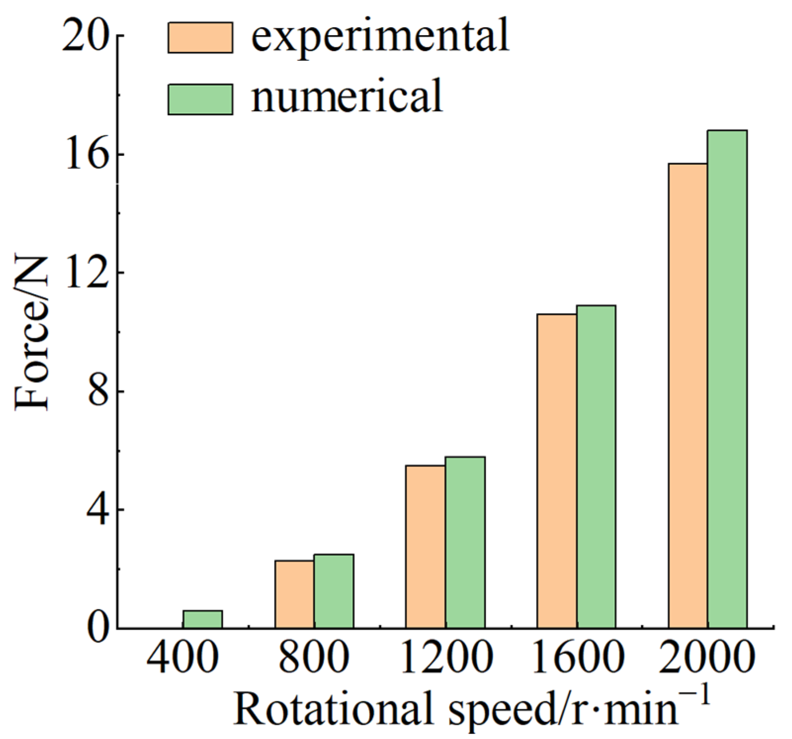
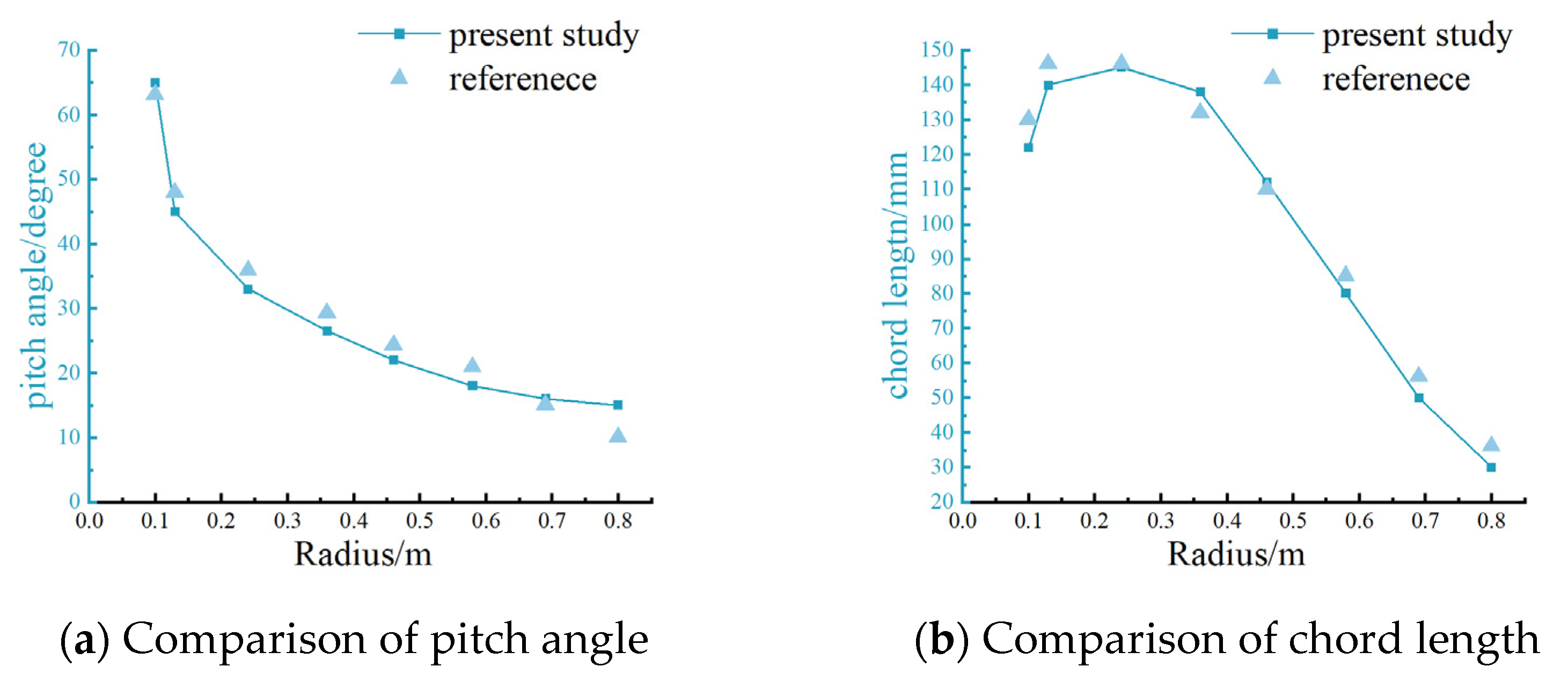
Section 3 validates the numerical simulation methods used, including mesh independence verification, reproduction of previous results, and experiments.
Section 4 presents the efficiency and detailed flow characteristics of propellers under different design methods. In addition, the influence of the maximum chord location along the blade on the overall propeller efficiency is examined. Finally, the paper discusses the mechanism of the proposed design and offers prospects for future design. The results of this study can provide useful references for improved propeller efficiency.
2. Methodology
2.1. Design Method
The traditional propeller design method is determined using Blade Element Theory (BET) and Vortex Theory. These theories achieve low-cost design evaluation by neglecting complex flow effects, while maintaining strong engineering applicability.
Figure 1 illustrates the calculation procedures of blade element theory and vortex theory. In the optimal propeller design based on blade element theory, the Lagrange multiplier
represents a proportional factor that balances efficiency maximization with thrust requirements under the thrust constraint.
The specific calculation steps of the blade element theory are described in Reference [
28], which divides the propeller along its radial position into
sections. Using the specified thrust
, flight speed
, rotational speed
, blade number
, propeller radius
and hub radius
, together with the airfoil characteristics, the sectional chord length and pitch angle distributions are obtained.
Figure 2 below illustrates a schematic of the blade element cross-section.
In propeller design using blade element theory, the first step is to obtain the constant
k by integrating the equations shown in the flowchart, followed by determining the chord length
of each section. According to the study by Xiang et al. [
28], these values are derived from a chord distribution function governed by a coefficient ranging from 2 to 100. Subsequently, the nondimensional chord length
of each blade section can be expressed as
where
, with
being the chord length of a wing section, and
representing the maximum chord length among all cross-sections.
is the dimensionless radial coordinate of the
-th section, and
is the dimensionless radial coordinate of the cross-section with the maximum chord length.
Next, the pitch angle
of every blade section is evaluated, as expressed by
where
is the angle of attack at which the airfoil section achieves the maximum lift-to-drag ratio, and
is the advanced ratio. Putting the chosen airfoil into Xfoil, the required value is determined, taking into account the local Reynolds and Mach numbers for each cross-section. The corresponding formulas are provided in Reference [
28].
By applying Equations (4) to (6), the chord length and pitch angle for each cross-section are calculated.
Propeller vortex theory is a more accurate theory than blade element theory. It considers the vortex structures induced by the propeller blades in the air. This allows a more realistic description of the interaction and relationship between the propeller and the airflow. In vortex theory, the downwash flow caused by the superposition of two-dimensional airfoil circulation reduces the effective angle of attack.
At the radial position
a small segment length
is selected, with the corresponding blade element chord length
. During flight, the blade element moves along a helical path. The flight speed is
, and the tangential velocity in the propeller rotation plane is
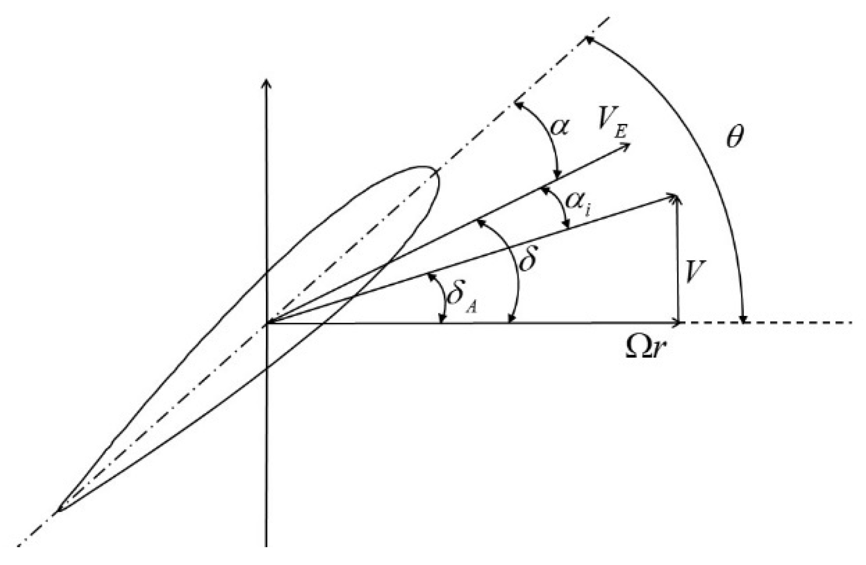
. The force diagram of a blade element in vortex theory is shown below in
Figure 3.
The geometric resultant velocity of the airflow relative to the blade element:
The angle between the geometric resultant velocity and the rotation plane is
Let the blade element installation angle be
(the angle between the blade element chord line and the rotation plane), and let
be the interference angle caused by the tip vortex. The actual airflow velocity angle is
Therefore, the angle of attack of the airflow relative to the blade element is
(1) Given the inflow velocity , blade element radius , propeller diameter , propeller rotational speed , blade element pitch angle , number of blades , hub diameter , and blade element chord length , the following parameters can be further obtained.
Geometric angle of attack:
(2) To determine the interference angle, the Newton iteration method can be used. Assume the interference angle is
. Then, the angle of attack of the airflow relative to the blade element is
The lift coefficient and drag coefficient of the blade element are calculated. Then, the angle corresponding to the ratio of drag to lift of the blade element s calculated.
where
.
if the difference between
and
meets the allowable error, the iteration ends; otherwise, values are recalculated. The error used in this paper is limited to below 0.0005.
2.2. Body-Fitted Design Method
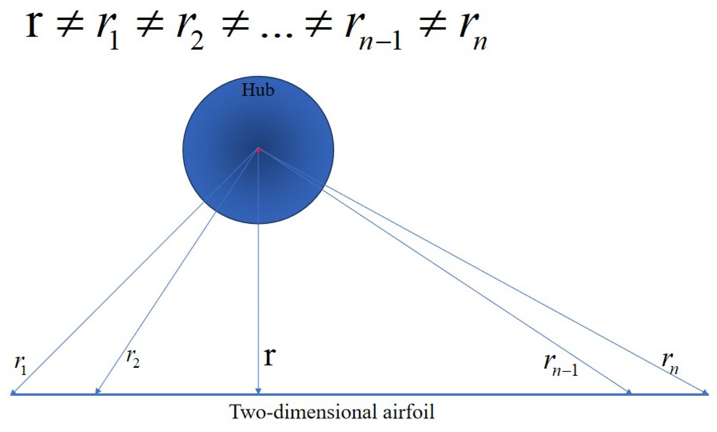
When designing high-altitude, high-thrust propellers based on blade element and vortex theories, the aerodynamic performance may be compromised by factors such as compressibility effects, low Reynolds numbers, the inapplicability of existing airfoil data, and the neglect of complex three-dimensional and unsteady phenomena (e.g., tip vortices and aeroelastic deformation). In addition to these physical challenges, the classical blade element method itself introduces geometric deviations: within the same plane, the distances from element nodes to the hub center are unequal, which can lead to inconsistencies between the designed geometry and the actual flow streamlines. To address this, the concept of body-fitted blade design is introduced. As shown in
Figure 4, an ellipse is constructed along the chordwise direction to ensure equal node distances from the hub, and the airfoil surface is subsequently fitted to the ellipse, thereby improving the geometric consistency and aerodynamic prediction accuracy.
In the process of designing the body-fitted geometry, it was found that performing integration over the introduced hypothetical elliptical cylindrical surface is highly challenging. The expression for its perimeter
is given as follows:
where
is the semi-major axis of the ellipse,
is the eccentricity of the ellipse.
This integral is an elliptic integral, and elliptic integrals (including those of the first and second kinds) cannot be expressed in terms of a finite combination of elementary functions such as polynomials, exponentials, logarithms, or trigonometric functions. This is a well-established result in mathematical analysis. Since an analytic solution is not attainable, numerical integration methods and approximate formulas are typically employed to calculate the circumference of an ellipse.
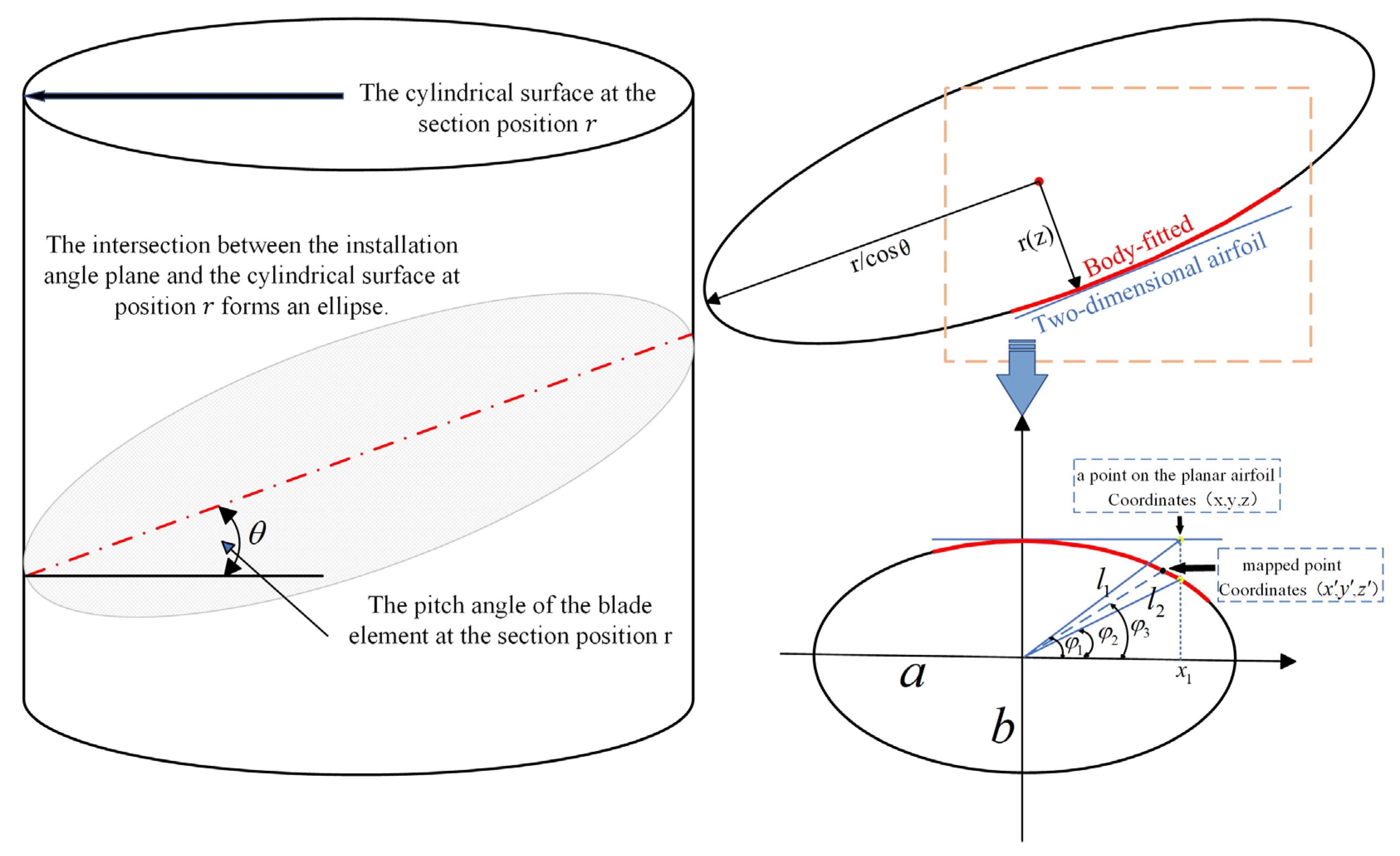
The following describes the two-dimensional airfoil processing procedure: The coordinates of points on the two-dimensional airfoil are set as
,
, and
, where
also represents the section position of the blade element. The specific schematic is shown in
Figure 5 below.
(1) In a two-dimensional wing, the quarter-chord point (near the leading edge) is considered the wing’s center position. The distance from the leading edge to this point as
. Then, translate the entire airfoil along the x-axis so that the quarter-chord point aligns with the origin of the coordinate system. Therefore, the coordinates of the points after translation become
,
, and
.
(2) The pitch angle of the blade element is
, which is converted into radians. Meanwhile, the major axis
and the minor axis
of the ellipse used for body-fitting are calculated.
The obtained ellipse equation is as follows, where
is the parametric angle in the ellipse equation.
(3) Before transformation, the distance
from each point on the two-dimensional airfoil to the hub origin is calculated, followed by the deviation angle
of each point in the x-direction.
(4) The distance
from each projected point on the ellipse to the hub origin is calculated, as well as the deviation angle
of each point in the x-direction.
(5) Mapping angle
used for transformation is determined.
When calculating the angle , it was found that evaluating the elliptic integral was too difficult. Therefore, in this study, the mapping angle was obtained through an approximate method. This method first calculates the angle between a point on the two-dimensional airfoil and the x-axis (), as well as the angle between the perpendicular projection of that point on the ellipse and the x-axis (). The mapping angle () is then determined as the mean of these two angles. This approach provides a direct and efficient way to determine the intermediate mapping angle without solving elliptic integrals.
However, this approximate method inevitably introduces some deviations, since the averaged angle does not strictly correspond to the exact solution of the elliptic integral. Errors mainly occur in regions of high curvature, such as near the blade root or tip, where geometric nonlinearities are more pronounced. Preliminary comparisons with exact numerical solutions indicate that when the aspect ratio of the fitted ellipse is moderate, the geometric deviation introduced by this angle-averaging scheme is generally within a few percent, but in highly eccentric geometries, the deviation can increase significantly.
Nevertheless, since the aim of this study is to investigate aerodynamic trends and the relative influence of design parameters rather than to achieve exact geometric reproduction, the approximations are considered acceptable.
Finally, the coordinates
,
, and
of each point on the transformed airfoil are obtained.
4. Results and Discussion
To verify the effectiveness of the proposed blade-conforming design method, propellers were first designed using blade element theory and vortex theory, and then the blade-conforming design was applied to each of these propellers. The corresponding modeling parameters and specific model designs were obtained for each method. Numerical calculations were then performed on all four propellers to determine their efficiencies.
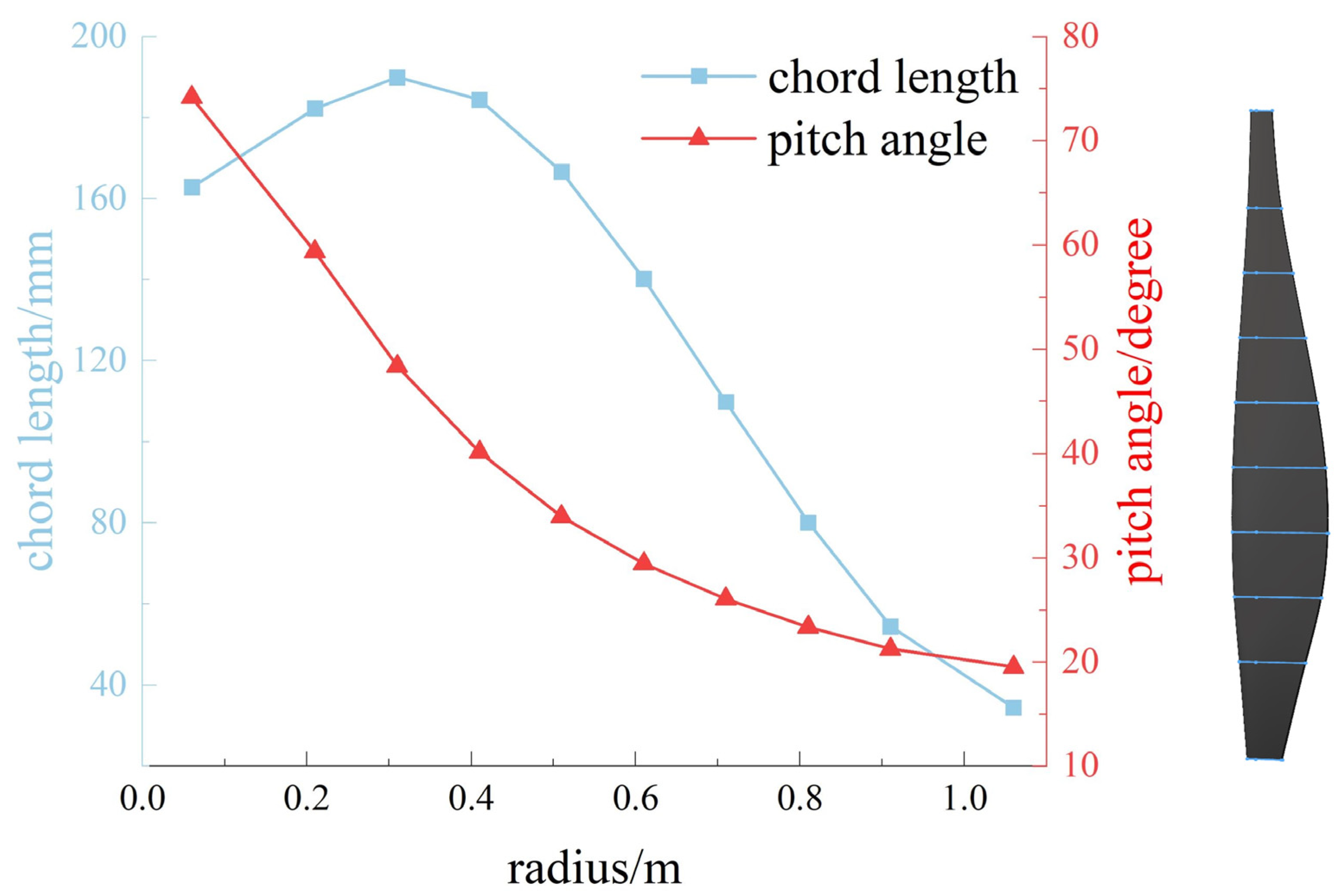
The specific design requirements for the propeller used in this study are for a high-altitude, high-thrust electric UAV propeller requested by a certain company. The propeller was designed for a thrust of 3400 N, a flight altitude of 4.5 km, a flight speed of 47.22 m/s, and a rotational speed of 2200 rpm. The blade length is 1 m, and the position of the maximum chord is located at 0.3 of the blade span. The parameters calculated using blade element theory are shown in
Figure 12 below.
The propeller obtained above was further designed using vortex theory. Due to the introduction of the interference angle, the chord length distribution and pitch angle distribution changed accordingly. The specific parameters are shown in
Figure 13 below.
The propeller designed using blade element theory was processed with the body-fitted method, resulting in the propeller model shown in
Figure 14.
The propeller designed using vortex theory was further processed with the body-fitted method. Each blade element plane was bent to fit the elliptical surface at the corresponding cross-sectional position. The detailed model is shown in
Figure 15 below.
The thrust and efficiency of the three propellers obtained from numerical simulations are shown in
Table 1. The propeller efficiency is calculated based on the thrust
and moment
obtained from the simulation. The calculation formula is as Equation (34).
The thrust of the propeller after body-fitted design is slightly reduced. This is because the use of curved, body-fitted two-dimensional airfoils leads to a decrease in the actual blade surface area, which in turn reduces the propeller disk solidity and results in a lower thrust output. For propellers designed based on blade element theory, the body-fitted design method can significantly improve efficiency while maintaining thrust. The fundamental reason is that blade element theory has limited accuracy and neglects many flow details and effects, whereas the body-fitted design allows better matching with the actual flow field characteristics, thereby enhancing overall performance.
To investigate the aerodynamic performance and mechanism of the fitted propeller design, contour plots of flow velocity on the rotation plane and turbulence eddy dissipation on the blade surface were extracted. The results show that the eddy dissipation near the leading edge and the blade tip is significantly higher than in other regions. Compared with the other two designs, the fitted propeller has a smaller dissipation area and lower dissipation rate near the leading edge, which effectively improves efficiency. The results indicate that, after the correction with vortex theory, the propeller exhibits a smaller contour area in Turbulence Eddy Dissipation, resulting in a further improvement in efficiency. Moreover, the reduction in turbulence intensity contributes to the decrease in propeller noise. The comparison of contour plots is shown in
Figure 16.
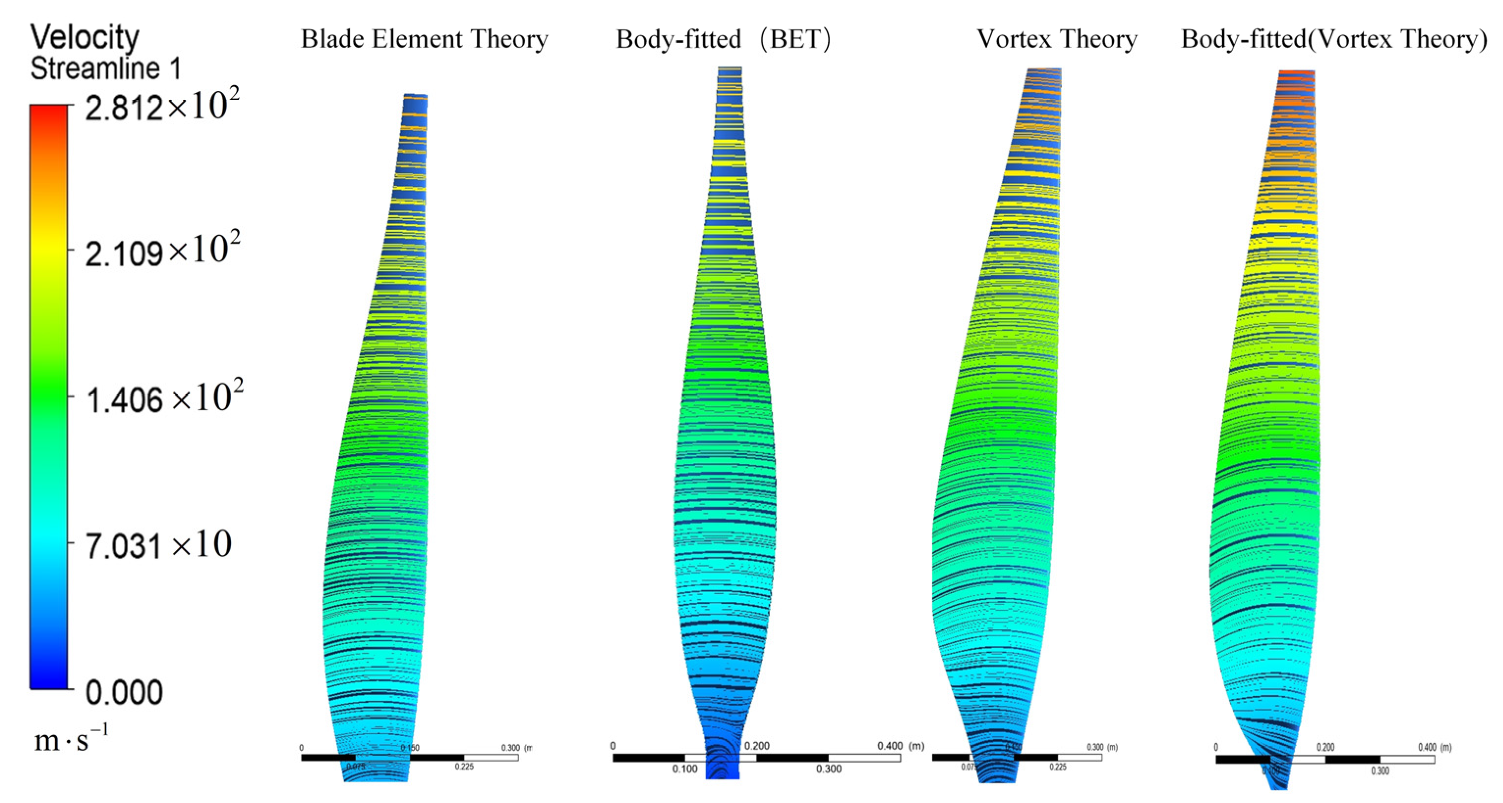
Figure 17 presents the velocity streamlines on the propeller blade surfaces designed using three different methods: blade element theory, vortex theory, and the proposed body-fitted airfoil approach. The flow characteristics along the blade surfaces can be clearly observed. As shown in the figure, the propeller designed with conventional blade element theory exhibits noticeable flow bending and disorder in the mid-to-rear regions, indicating that this method does not fully account for aerodynamic interference and surface fitting effects. In contrast, the propeller designed using vortex theory demonstrates improved flow guidance, with smoother and more organized streamlines. Furthermore, the body-fitted design results in more continuous streamlines that closely follow the blade contour, suggesting that the curved surface modeling enhances flow attachment and reduces the risk of flow separation, thereby improving aerodynamic performance.
In summary, the body-fitted design shows clear advantages in organizing the flow field compared to traditional methods, highlighting its potential for improving propeller efficiency.
In this study, it is found that blade element theory (BET) is not suitable for the design of high-thrust propellers. This is because BET divides the propeller blade into a series of independent two-dimensional airfoil sections, ignoring the mutual interference between blade elements and the curvature effects of the blade surface. Moreover, under high-thrust conditions, the flow curvature and streamline deflection become more pronounced, making BET incapable of accurately capturing aerodynamic details. BET also expands the blade based on two-dimensional airfoil sections, disregarding the curvature of the blade surface on the rotating cylindrical plane. Such geometric deviations become more significant in designs with large blade lengths and chord lengths, thus reducing modeling accuracy and aerodynamic prediction reliability.
Although the proposed body-fitted design method improves aerodynamic efficiency, several limitations should be noted. First, as the increase in propeller size may introduce additional structural and aerodynamic complexities, further investigation is needed to assess the scalability of this method for large UAV propellers. Second, although the method proposed in this study does not account for aeroelastic effects, which may influence blade deformation, it is based on a qualitative analysis of the overall aerodynamic performance of the propeller, thereby ensuring the scientific validity of the study to the greatest extent possible. Finally, compressibility effects at higher flight speeds are not included in the analysis; incorporating these effects is essential for extending the applicability of this method to high-speed flight conditions. These aspects will be the focus of our future work.
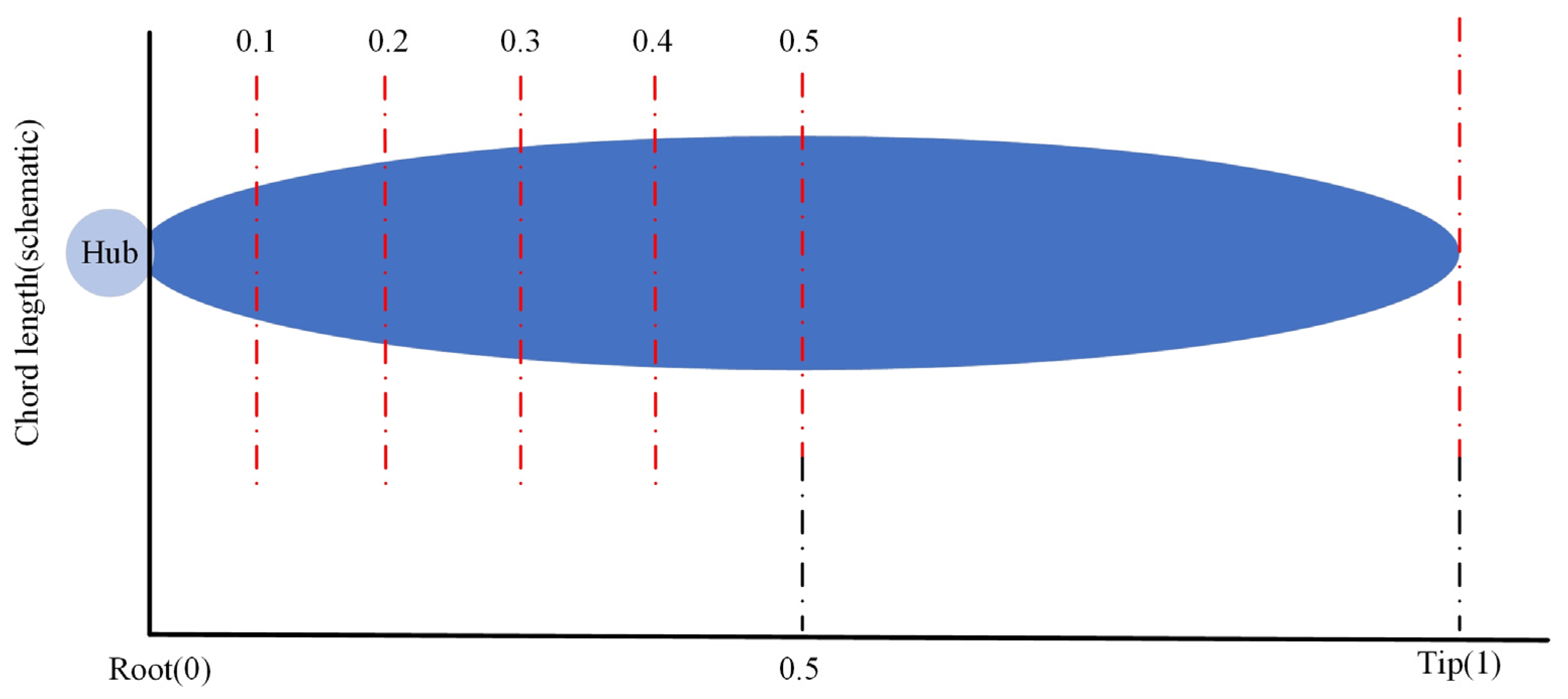
In the design process, to further investigate the influence of the maximum chord position on the aerodynamic performance of the propeller, five propeller models were developed based on the previously established propeller configuration. The maximum chord of these models was located at 0.1, 0.2, 0.3, 0.4, and 0.5 of the blade span (measured from the root toward the mid-span), respectively. The thrust variations among these configurations were analyzed to evaluate the effect of different chord positions under the proposed design method. A schematic illustration is shown in
Figure 18.
By calculating the efficiencies of the five propeller sets, the efficiency-position curve is obtained as shown in
Figure 19. The results indicate that when the maximum chord is located in the 0.1–0.3 span of the blade, the overall propeller efficiency increases rapidly. For the designed propeller, when it is located in the 0.3–0.5 span, the efficiency decreases gradually. Therefore, positioning the maximum chord in the 0.3–0.4 span is beneficial for improving the overall propeller efficiency.
5. Conclusions
This paper proposes a design method for propeller energy conversion efficiency based on blade element theory and vortex theory. To address the computational errors caused by varying distances from points on the 2D airfoil to the hub center, a body-fitted design approach is introduced. In this approach, the 2D airfoil is bent to conform to the actual geometry for propeller modeling.
(1) By introducing vortex theory, the traditional blade element theory was modified. Simulation results show that the propeller designed based on vortex theory achieves a 3.4% improvement in efficiency compared to the one designed using the original blade element theory.
(2) A body-fitted design concept was proposed, which fully accounts for the errors introduced by the varying distances from different points on the planar airfoil to the rotation center. Based on this concept, a propeller was modeled and simulated. The results show that the propeller designed using the body-fitted approach achieves a 4.2% increase in efficiency compared to the propeller designed using blade element theory. Meanwhile, for propellers designed based on blade element theory, the body-fitted design method can significantly improve efficiency while maintaining thrust.
(3) Researchers conducted experimental tests by placing the maximum chord at different positions along the propeller blade. The maximum chord was set at 0.1, 0.2, 0.3, 0.4, and 0.5 of the blade span. The results showed that propellers with the maximum chord located between 0.3 and 0.4 achieved higher overall efficiency compared with other positions.
This method offers a new perspective for future propeller design, particularly for high-thrust propellers.

