Abstract
Sling configurations significantly influence the coupled dynamics of the helicopter with slung load system (HSLS), resulting in alterations to handling qualities (HQs) that remain inadequately understood. This study introduces a computer-oriented, generalized method for constructing the HSLS model with various sling configurations. To evaluate the HQs of 1-point, 2-point, and 4-point sling configurations, both the stability and response criteria outlined in ADS-33E and a newly proposed criterion for slung loads towards the updated ADS-33F were employed. Modal analysis was conducted to elucidate the coupled mechanisms of the HSLS under different sling configurations. The findings reveal that the dynamics of the main rotor can attenuate the lateral swing motions of the load in the 4-point sling configuration. While multiple-point sling configurations can enhance the helicopter’s bandwidth, they also amplify the magnitude notch in the helicopter’s response. Nevertheless, when a larger hook distance is employed, the notch frequency is sufficiently distant from the load swing bandwidth, leading to a reduced degradation in HQs. A 4-point configuration with lateral and longitudinal hook distances equal to twice the width and length of the slung load is recommended in practice to achieve sufficient swing stability and mitigate HQ degradation.
1. Introduction
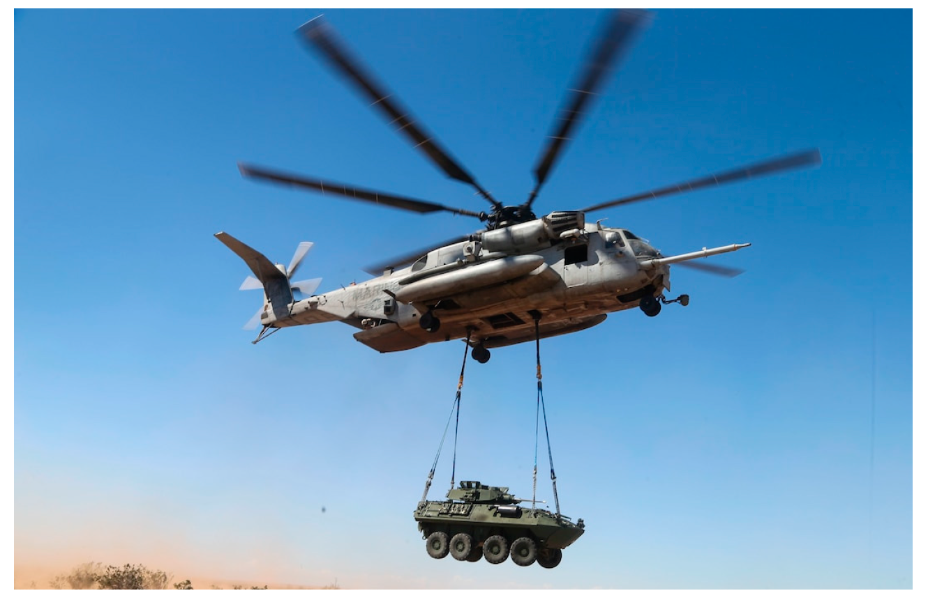
Helicopters are versatile aircraft capable of performing a variety of tasks, including the transportation of external loads suspended beneath the fuselage. Various sling configurations for slung load operations have been introduced in Ref. [1]. Although the 1-point sling configuration is the most commonly used, other configurations have distinct advantages. For instance, as shown in Figure 1, 2-point sling configurations can constrain load yaw motions, thereby preventing the load spinning as usually observed in the 1-point configuration. This is particularly important for bulky loads, which often have unstable yaw aerodynamics.
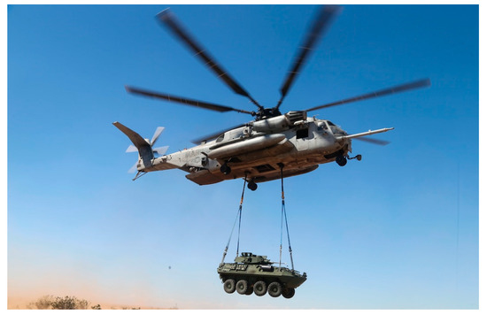
Figure 1.
Illustration of 2-point sling configuration in practical use “https://dod.defense.gov/OIR/gallery/igphoto/2001644332/ (accessed on 6 July 2024)”.
The dynamic motions of slung loads are known to negatively impact the helicopter’s handling qualities (HQs), leading to potential safety risks and operational difficulties [2]. Consequently, assessing HQ for the helicopter with slung load system (HSLS) is crucial in slung load operations. Most attention has been given solely to the 1-point sling configuration, where all slings are connected to a single point on the helicopter fuselage, with limited HQ assessments for other sling configurations.
The well-known criteria for helicopter HQ assessment is the U.S. Army Aeronautical Design Standard for rotorcraft handling qualities, ADS-33E [3,4]. Although the requirements are tailored for situations with external slung loads [5], it does not include quantitative criteria for slung load operations. Many efforts have been devoted to HQ evaluation for slung load operations. Hoh [6] proposed HQ criteria based on ground-based simulations. However, subsequent applications of these criteria were not completely successful [7]. Afterwards, a new qualitative criterion was developed based on flight tests and pilot ratings [2]. This criterion was then improved and added to the proposed revisions to ADS-33E towards ADS-33F [8]. However, whether this new qualitative criterion is suitable for different sling configurations remains to be discussed.
The negative effects of slung loads on HQ are primarily due to a prominent oscillatory mode in the frequency range of manual control activity, associated with load swing motion and its coupling with the helicopter. This coupling can lead to complex interactions that are difficult to predict and manage. Numerous studies have focused on HSLS modeling to understand the coupled dynamics and reveal the mechanism of HQ degradation. Guglieri and Marguerettaz [9] assessed the impact of the slung load on HSLS stability, helicopter response, and HQs based on a comprehensive HSLS model. Cicolani et al. [10] studied the effects of slung loads on helicopter frequency response based on flight tests of a UH-60A with a slung load, utilizing the system identification method. A significant magnitude notch in the frequency range of manual activities was observed in helicopter frequency responses. Sahasrabudhe et al. [11] revealed that HQ degradation cannot be prevented to ensure stability margin requirements with heavy slung loads. However, these studies mainly focus on the 1-point sling configuration. Although there is research on the 2-point configuration [12,13,14,15], it has mainly focused on coupled dynamics analysis while the effects of different sling configurations on HQ remain unknown.
As different sling configurations result in different couplings between the helicopter and the load, HQs vary accordingly. To reveal the inherent mechanism of HQ variations across different sling configurations, a coupled HSLS model supporting various sling configurations should be established. Several generalized methods have been presented for modeling various sling systems. Cicolani et al. [16] developed the unified method to establish equations of motion (EOMs) of HSLS based on the Newton–Euler formulation. Bisgaard et al. [17] presented a generalized HSLS modeling method based on the Udwadia–Kalaba theory. Ren et al. [18] utilized the unified Lagrange equations for establishing an HSLS model. Cao et al. [19] developed an HSLS model using Kane’s method and emphasized the importance of accounting for sling flexibility in modal analysis and stability. However, these approaches often require manual derivation of equations of motion (EOMs) for each sling configuration. Additionally, while unified modeling methods in multibody dynamics are well-established, they can be overly complex for the specific needs of HQ assessment. Previous studies have demonstrated that modeling each sling as a spring is sufficient to achieve accurate HQ assessment results [9,10,20]. Consequently, there is a need for a simplified yet generalized modeling method that incorporates sling flexibility and provides a clear formulation to analyze the inherent couplings in HSLS across various sling configurations.
In this paper, we present a detailed assessment of the handling qualities of helicopter with slung load systems using multi-point sling configurations. To accommodate various sling configurations, we introduce a computer-oriented generalized method for establishing the sling system model. This approach simplifies the description, modeling, and programming of arbitrary sling systems, offering advantages such as automatic sling system modeling and a clear Newtonian formulation. Using this approach, HSLS models for three different sling configurations were developed. The HQs of these configurations were evaluated based on HQ criteria in ADS-33E and the proposed revisions. The inherent coupled dynamics of the HSLS across different configurations are analyzed through eigenvalue and modal analyses, with a focus on the impact of sling configurations and hook distances on HQ.
The subsequent sections of this paper are organized as follows. Section 2 describes the modeling and validation of the HSLS. In Section 3, the coupled dynamics and HQs of the HSLS are assessed, analyzed, and discussed, including the effects of hook distance in multiple-point sling configurations. Section 4 provides concluding remarks.
2. HSLS Modeling and Validation
Figure 2 illustrates three configurations of helicopter slung load systems (HSLS) with 1, 2, and 4 hook points on the helicopter fuselage, referred to as the 1-point, 2-point, and 4-point sling configurations. To compare the handling qualities (HQs) of these sling configurations, an HSLS model supporting various configurations must be established. The commonly used HSLS model typically combines the GenHel helicopter model with a slung load system model. However, the helicopter and the slung load system are connected manually. Consequently, any change in the sling configuration necessitates a manual re-establishment of the HSLS model, making it complicated to analyze the effects of different sling configurations on HQs.

Figure 2.
Illustration of helicopter with slung load system.
In this section, a generalized sling system model capable of connecting the helicopter and the load accommodating various sling configurations is presented. An arbitrary sling system is discretized into mass nodes and spring-damper systems while a Boolean topology matrix is used to describe the sling configuration. The generalized sling system model in this paper employs a topology matrix to describe the sling configuration, facilitating easier programming. Additionally, the equations of motion for the generic sling system model are derived based on Newtonian mechanics, making the physical interpretation more straightforward.
2.1. Generalized Sling System Model for Various Sling Configurations
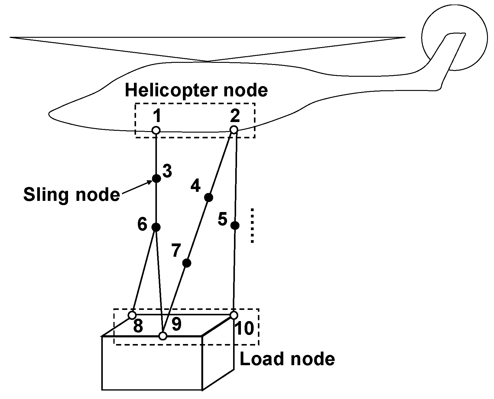
Figure 3 depicts a sample sling configuration, which is deliberately unusual to demonstrate the versatility and generality of the generalized sling system model. Slings are modeled as connected mass-spring-damper systems. Sling mass is distributed on solid dots while hollow dots are assumed massless. Solid lines between two dots are spring-damper systems.
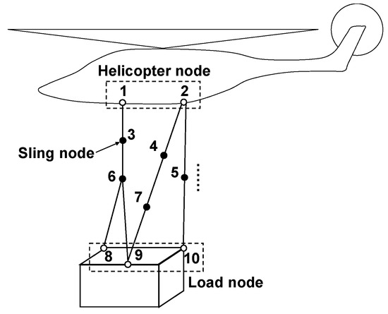
Figure 3.
Sample of sling configuration.
A Boolean topology matrix is used to describe the sling configuration. In order to achieve that goal, the solid dots and hollow dots should be numbered and classified at first. As shown in Figure 3, all dots are numbered one by one. Since hollow dot 1 and dot 2 are on the helicopter, they are called helicopter nodes. The solid dots numbered 3 to 7 are sling nodes. Hollow dots 8, 9, and 10 are on the load such that they are called load nodes. More generally, the numbers of helicopter nodes, sling nodes, and load nodes are denoted as , , and , respectively. Thus, the total number of nodes can be expressed as . It should be reminded that the indices of helicopter nodes are smaller than sling nodes, and smaller still than load nodes. With such a definition, the topology matrix of sling configuration can be expressed as
in which is the flag indicating if the -th and -th nodes are connected, which can be expressed as
For example, the topology matrix of the sling configuration as shown in Figure 3 can be expressed as
Given the position and velocity of each node, tensions in each sling can be obtained according to the above topology matrix. Let be denoted as the sling tension force vector, pointing from the -th to the -th node. It is obvious that . The expression of is
in which , , and are original length, stiffness, and damping of the spring-damper system connecting the -th and -th nodes. and are the relative position and velocity vectors of the -th node relative to the -th node. It should be noted that if the -th and -th nodes are not connected, i.e., , then .
Since slings are very thin, the aerodynamic force of slings can be neglected. However, for the completeness of the generalized sling system model, aerodynamic forces of the slings are assumed to be distributed on each sling node, which can be expressed as
in which is the airspeed of the -th node including node velocity, environment flow field, and main rotor downwash. is the drag coefficient of the -th node. is air density.
Based on the tensions and aerodynamic forces of slings, EOMs of the generalized sling system model can be expressed as Equation (6). The sling forces acting on the helicopter and the load nodes, , can be expressed as Equation (7):
in which and are mass and acceleration of the -th node. is the gravity vector. It should be noted that denotes the indices of sling nodes while denotes that of helicopter and load nodes. Since the helicopter and load nodes are located on the helicopter and the load, the sling forces acting on the helicopter and load nodes act on the helicopter and the load directly. Taking the sling system in Figure 3 as an example, and are sling forces acting on the helicopter, while , , and are sling forces acting on the load.
2.2. HSLS Model
The HSLS model consists of a helicopter model, a sling system model, and a load model. For the helicopter model, as rotor dynamics brings additional time delay to input responses, they should be considered in order to evaluate HQs effectively. The load is a rigid body model. A similar HSLS model has been introduced in Refs. [21,22]. However, only the 1-point sling configuration was supported. Additionally, blade and fuselage elasticity are not significant in HQ evaluation such that it can be neglected in this paper to improve efficiency.
The helicopter main rotor model is formulated with the high-order dynamics of main rotor motions. A three-state dynamic inflow model is used to simulate the dynamics of main rotor inflow. Nonlinear aerodynamic forces and moments of the main rotor are determined with blade-element theory. The airfoil lift and drag coefficients of the blade elements are obtained with an interpolation method based on the wind-tunnel test data. Different from Refs. [21,22], the main rotor blades are assumed to be rigid bodies considering flapping and lagging motions.
The helicopter tail rotor is assumed massless and its aerodynamic force is calculated based on rotor disk theory with uniform inflow. Aerodynamic forces of the helicopter fuselage, horizontal tail, and vertical tail as well as the load are calculated based on nonlinear wind-tunnel test data interpolation. The aerodynamics interference is also taken into consideration by superimposing the rotor wake flow components onto the local incoming flow components of the fuselage, horizontal stabilator, vertical fin, tail rotor, and the slung load.
The helicopter fuselage model and the load model are rigid bodies. Once the helicopter and load node motions are determined by the helicopter and load motions, the reaction forces of the sling system on the helicopter and the load are obtained from Equation (7), which are acted on their 6-DOF rigid-body dynamics.
The state-space form of the HSLS model is shown as follows:
in which is the HSLS state vector; is the control input vector, and is time;
in which , , , , are flapping and lagging motions for each main rotor blade; are main rotor dynamic inflow states; is the tail rotor uniform inflow state; are helicopter translational velocities; are helicopter rotational velocities; are helicopter attitudes; are the helicopter position in earth axes; , is the -th sling node position in earth axes while is its time derivative; refers to equivalent cable length from the helicopter hook point to the load center of gravity; are cable longitudinal and lateral swing angles; are their time derivatives; are rotational velocities and attitudes of the load; are collective level, lateral stick, longitudinal stick, and pedal displacements in the cockpit.
2.3. Validation
In order to prove the credibility of the HSLS model, the flight test data of a UH-60A carrying a CONEX container are used for validation [10]. Since the UH-60A helicopter is equipped with only a single hook for carrying slung loads, only flight test data from the 1-point configuration are available for validation. Basic parameters of the UH-60A and CONEX are listed in Table 1.

Table 1.
Basic parameters of UH-60A and CONEX.
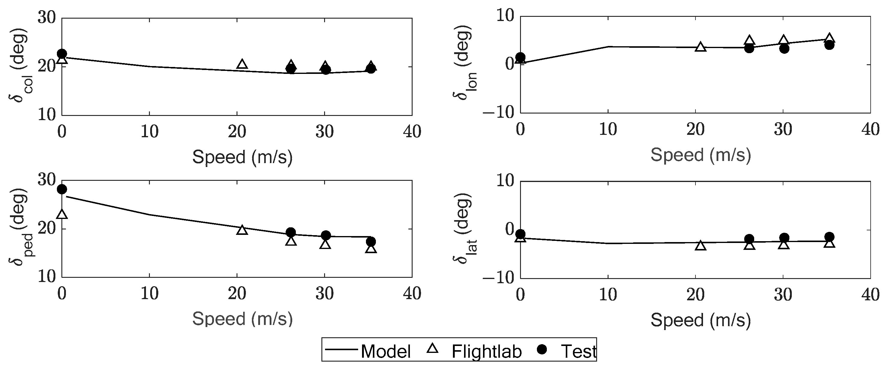
Figure 4 shows the trimmed helicopter controls of the HSLS. It can be observed that the model-calculated results are close to those of the flight test and Flightlab simulation [23], indicating the credibility of the HSLS model.
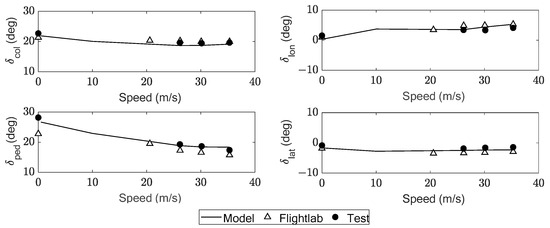
Figure 4.
Trimmed helicopter controls of the HSLS.
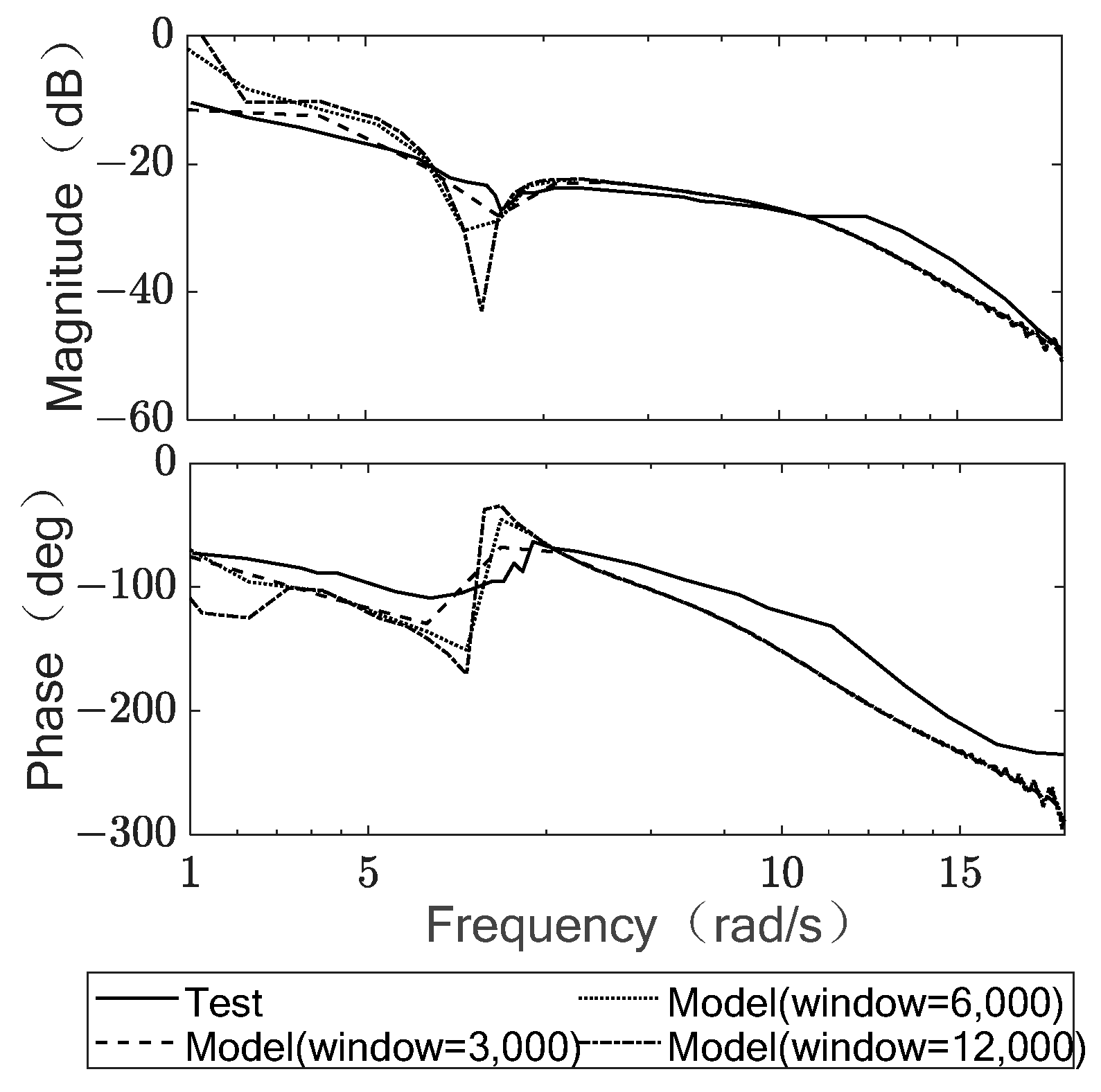
Since this paper is focused on assessing HQ, response characteristics should be validated in addition to trimmed characteristics. Response characteristics validation follows a similar procedure of system identification as the flight test. A frequency sweep of 0.4–20 rad/s is used to generate the time response of HSLS. A system identification tool based on Welch’s averaged periodogram method [24] is then used to estimate the frequency response. Given that window width is a critical parameter for system identification, Figure 5 is provided to demonstrate the consistency of window width selection between model simulations and flight test identifications. The sampling rate is 200 Hz. It can be observed that as the window width increases, the magnitude notch and phase lag phenomena become more pronounced, occurring at a load swing frequency of about 1.5 rad/s. This is because a longer window width improves frequency resolution. However, a longer window width also worsens noise reduction performance. Therefore, in practical applications, choosing an appropriate window width is crucial. As shown in Figure 5, a window width of 3000 aligns with the settings used in the flight test identification.
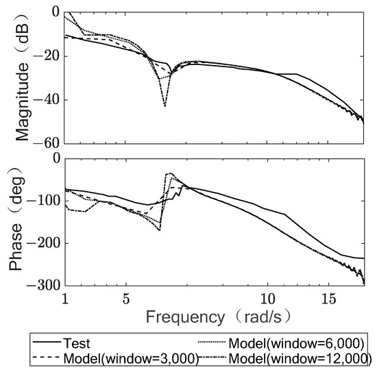
Figure 5.
Effects of window width on identification results.
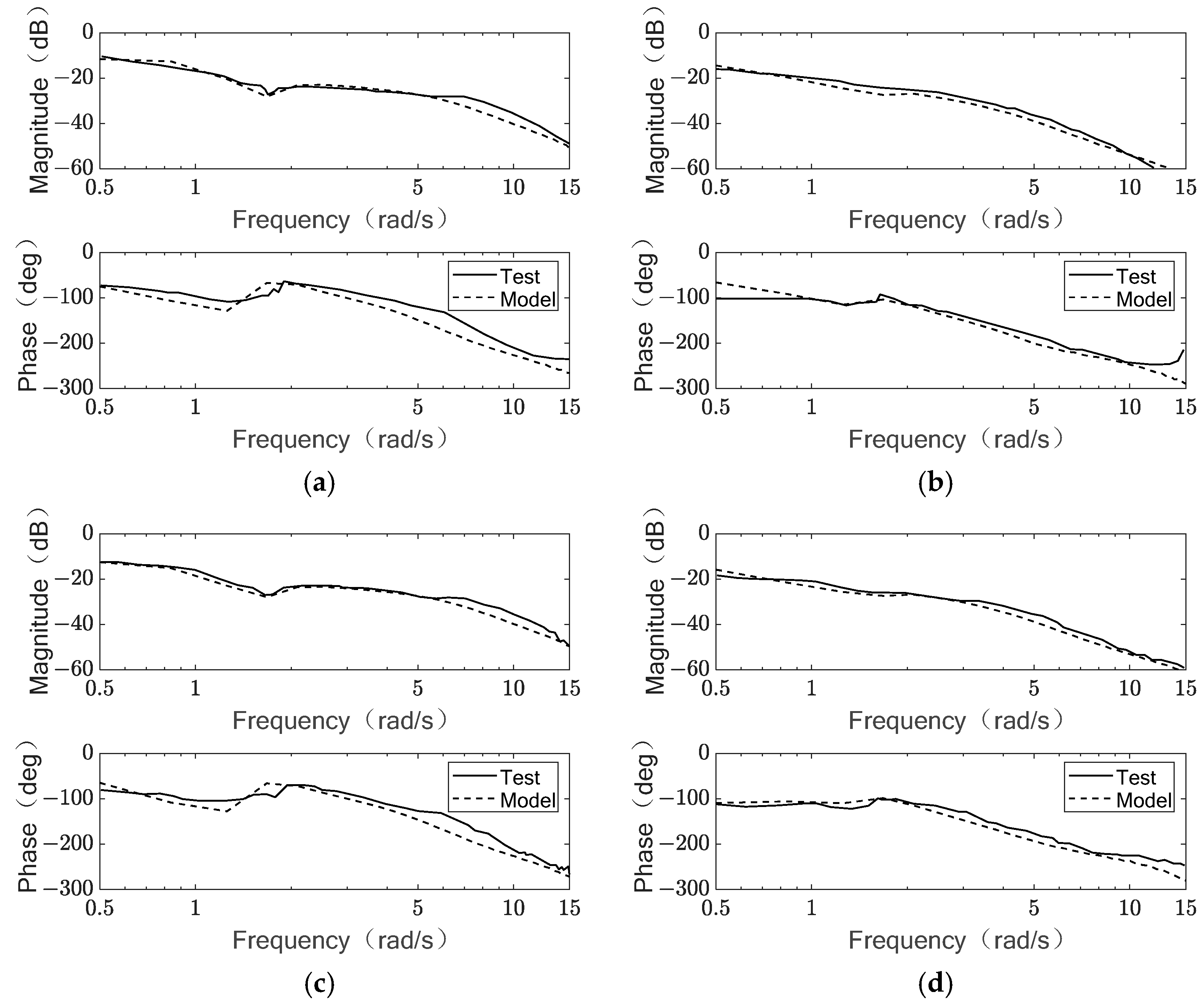
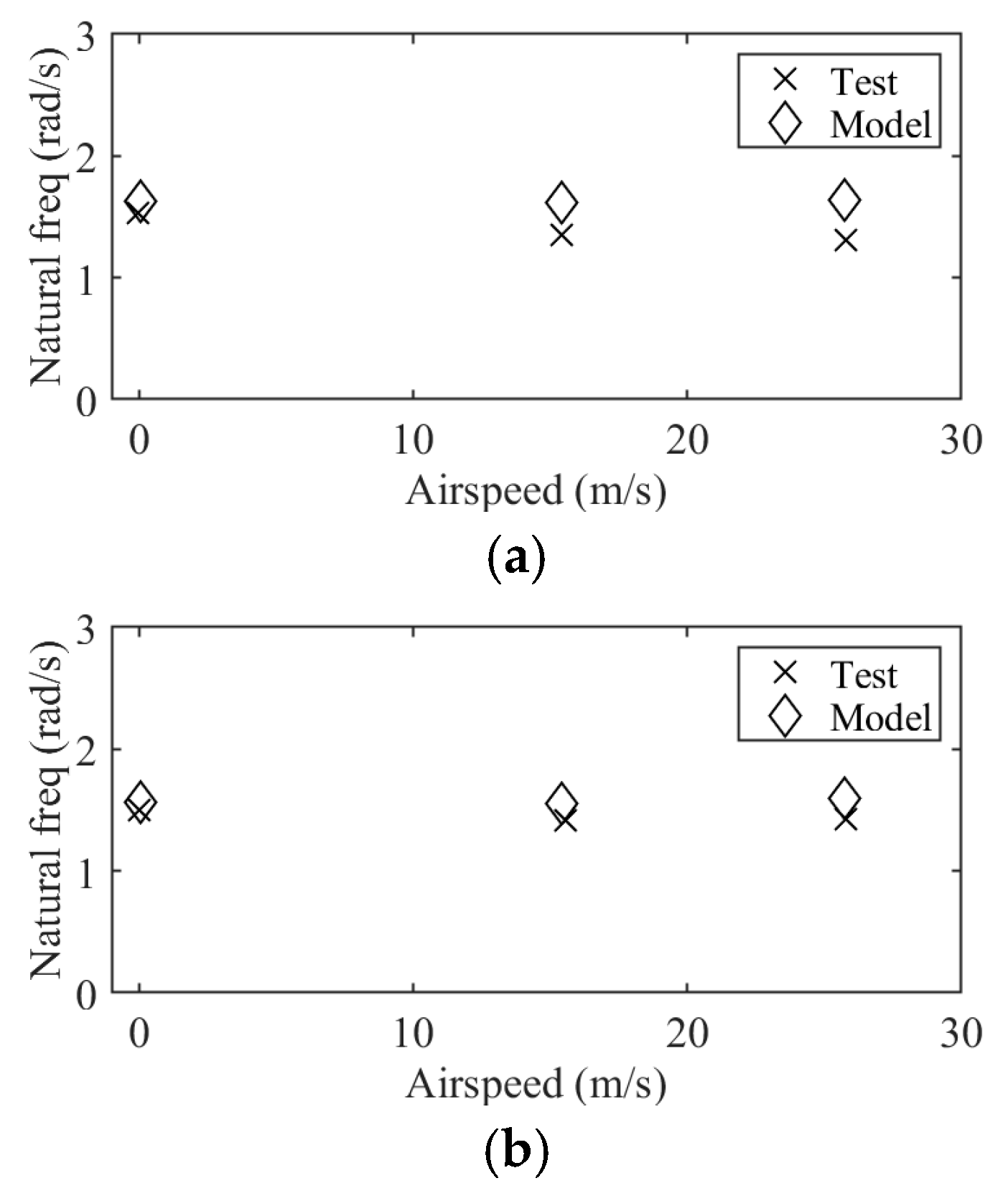
In the 1-point configuration, the helicopter’s yaw motion is not coupled with the load’s yaw motion, so only roll and pitch responses are validated. Figure 6 presents the validation results of the roll and pitch responses for the HSLS model in both hover and forward flight at 15.4 m/s. Figure 7 shows the validation results for load lateral and longitudinal swing frequencies. The close agreement between the model’s calculated frequency response and the load’s lateral and longitudinal swing frequencies with those observed in the flight test indicates that the model is accurate and suitable for HQ assessment.
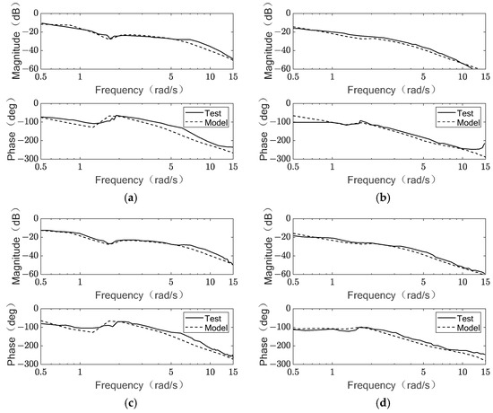
Figure 6.
Roll and pitch response validation for HSLS model. (a) Roll response in hover. (b) Pitch response in hover. (c) Roll response at 15.4 m/s. (d) Pitch response at 15.4 m/s.
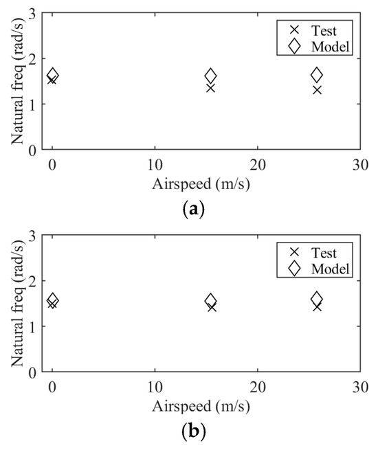
Figure 7.
Load lateral and longitudinal swing frequency validation for HSLS model. (a) Load lateral swing. (b) Load longitudinal swing.
3. Handling Quality Assessment and Discussion
The criteria specified in ADS-33E are used to assess the HQs of HSLS. HQs of hover and low speed flight are evaluated because the effects of unstable load aerodynamics are not significant. For slung load operations, the stability of oscillatory modes is crucial to avoid dangerous load swing oscillations. Additionally, helicopter attitude and heading changes to pilot inputs are essential for manipulating the helicopter. Moreover, the new criteria introduced in proposed revisions of ADS-33F address a new HQ requirement especially for slung load operations. Therefore, in this paper, we evaluate the above three HQ requirements for the 1-point, 2-point, and 4-point sling configurations and examine the effects of hook distance on HQs, using the HSLS parameters specified in Table 1.
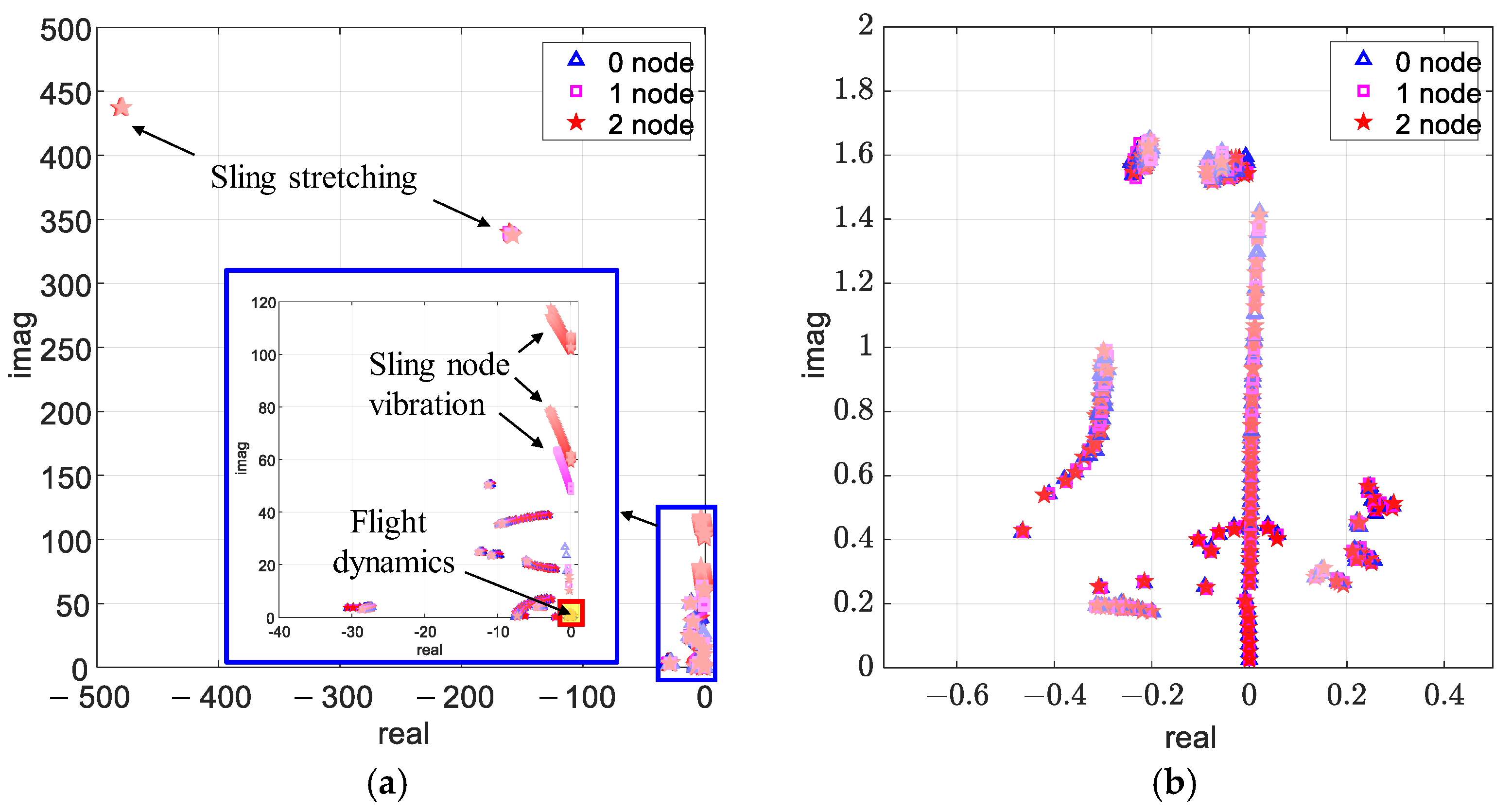
To determine the appropriate number of sling nodes, the impact of sling node number on HSLS dynamics was examined. Figure 8 shows all eigenvalues of the HSLS with each sling being divided by 0, 1, or 2 sling nodes. Figure 8a reveals that the number of sling nodes primarily influences high-frequency dynamics, introducing additional modes related to sling stretching and sling node vibration. However, these affected frequencies exceed 50 rad/s, whereas the frequency range pertinent to flight dynamics is below 10 rad/s. As shown in Figure 8b, a closer examination of the low-frequency range indicates that the number of sling nodes has minimal impact on flight dynamics. This is because the slings are lightweight with high stiffness, resulting in sling dynamics occurring at frequencies significantly higher than those of the flight dynamic modes. Consequently, for all sling configurations in subsequent analyses, the number of sling nodes is set to zero.
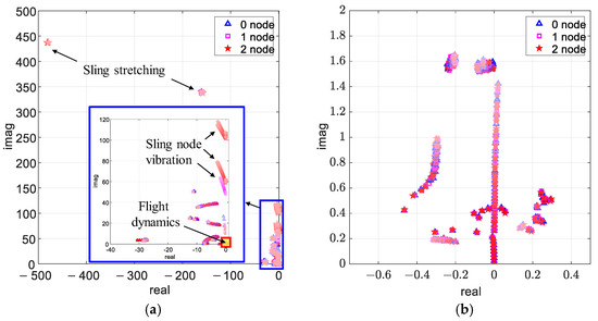
Figure 8.
1-point configuration eigenvalues of various sling node numbers and speeds. (a) Overall view. (b) Detailed view of flight dynamic modes.
Topology matrices of 1-point, 2-point, and 4-point sling configurations are listed as Equations (11)–(13).
3.1. Stability of Oscillatory Modes
The handling quality requirements on the stability of oscillatory modes are based on eigenvalues. The steps for assessing the stability of oscillatory modes are as follows. Firstly, the HSLS model is trimmed at a given speed and sling configuration. Then, the HSLS model is linearized at the trimmed state to obtain a linearized HSLS model, i.e., the system matrix, A, and the control matrix, B. Afterwards, the stability of oscillatory modes can be evaluated using the eigenvalues of the obtained linearized system matrix, A, which are plotted on the real-image figure along with the boundaries specified in ADS-33E. Meanwhile, the eigenvectors are visualized using the polar coordination system which illustrates the amplitudes and phases of the main state variables of the eigenvector.
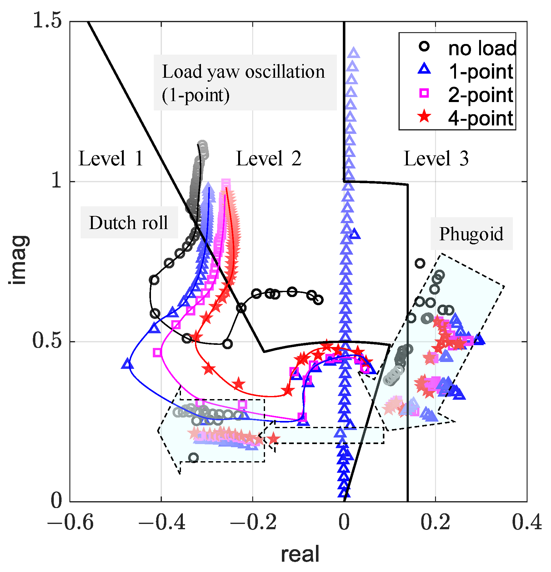
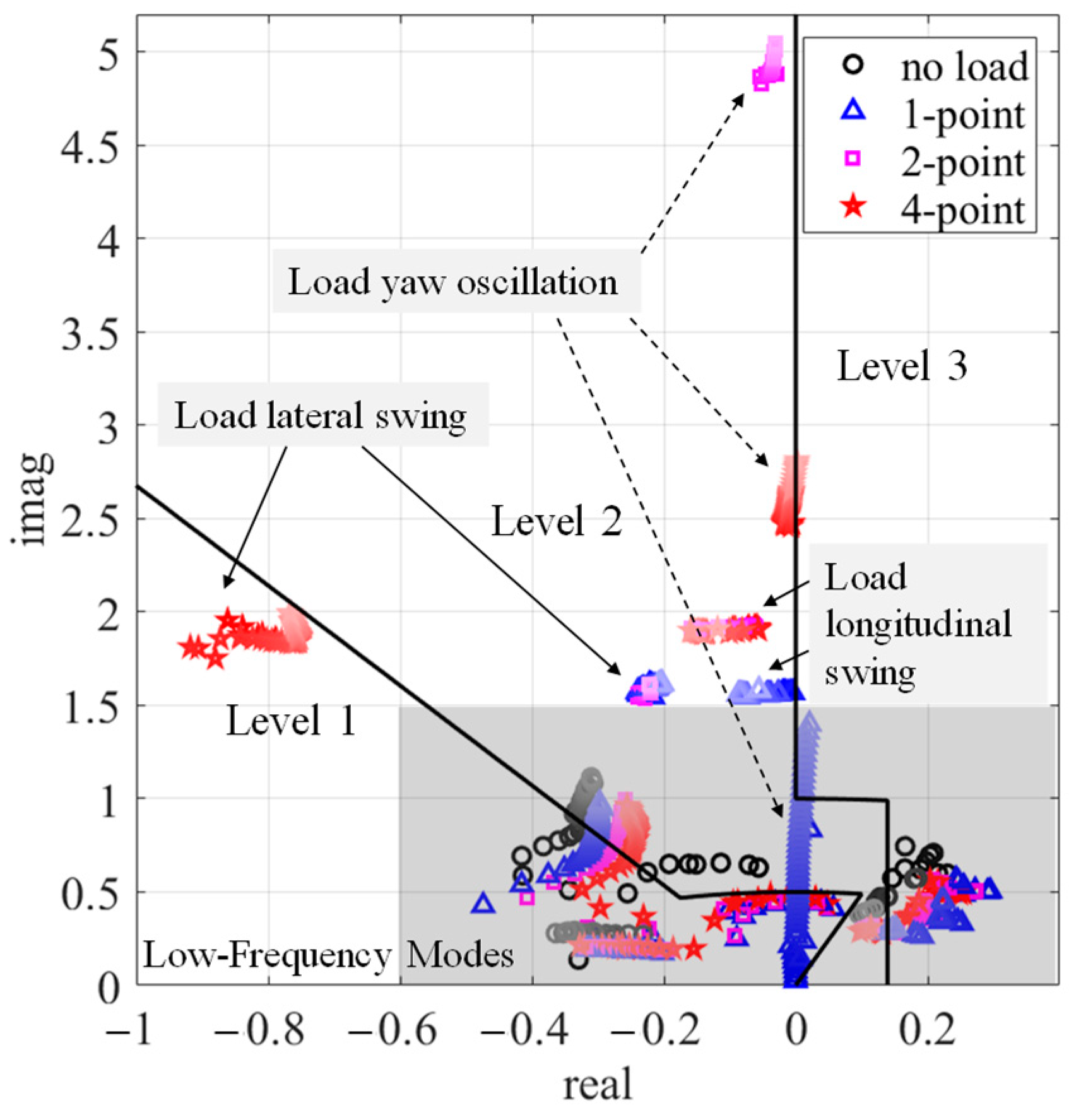
Figure 9 displays the low-frequency oscillatory mode eigenvalues for four cases and various speeds. For comparison, the case without a slung load is also included alongside three sling configurations. As speed increases, the stability of the helicopter’s Dutch roll mode and phugoid mode improves, although their responses to speed changes are different.
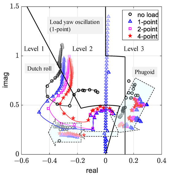
Figure 9.
Low-frequency oscillatory mode eigenvalues of 4 cases and various speeds.
For the phugoid mode, stability increases sharply and reaches the Level 1 HQ region at approximately 12 m/s. This improvement is attributed to the UH-60A helicopter’s horizontal tail being out of the rotor wake during hover. When the rotor wake reaches the horizontal tail at 12 m/s, it provides additional pitch damping. In contrast, for the Dutch roll mode, the real part of the eigenvalue shifts toward the Level 1 region rapidly at speeds below 5 m/s, while the imaginary part remains around 0.6. At speeds exceeding 5 m/s, the real part stays at around −0.4, and the imaginary part increases with speed.
When carrying a slung load, the Dutch roll mode becomes unstable in hover. However, as its frequency decreases to less than 0.5 rad/s, it falls within the Level 1 HQ region. The phugoid mode, conversely, remains within the Level 2 and Level 3 regions at speeds below 12 m/s, with the presence of a slung load further deteriorating its stability. This observation indicates that carrying a slung load has negative effects on the helicopter’s low-frequency dynamics, leading to decreased stability and frequency, regardless of the sling configuration used and lateral/longitudinal motions. However, as the oscillatory mode frequencies decrease, the instability can be more acceptable.
The eigenvalues for the Dutch roll and phugoid modes are very similar across the 1-point, 2-point, and 4-point configurations. However, a slight difference can be observed that, as the hook points increase, the Dutch roll mode exhibits a lesser decrease in frequency but a larger decrease in stability. Meanwhile, the phugoid mode exhibits a lesser decrease both in frequency and stability. Therefore, sling configurations with multiple hook points benefit helicopter longitudinal dynamics while deteriorating lateral dynamics.
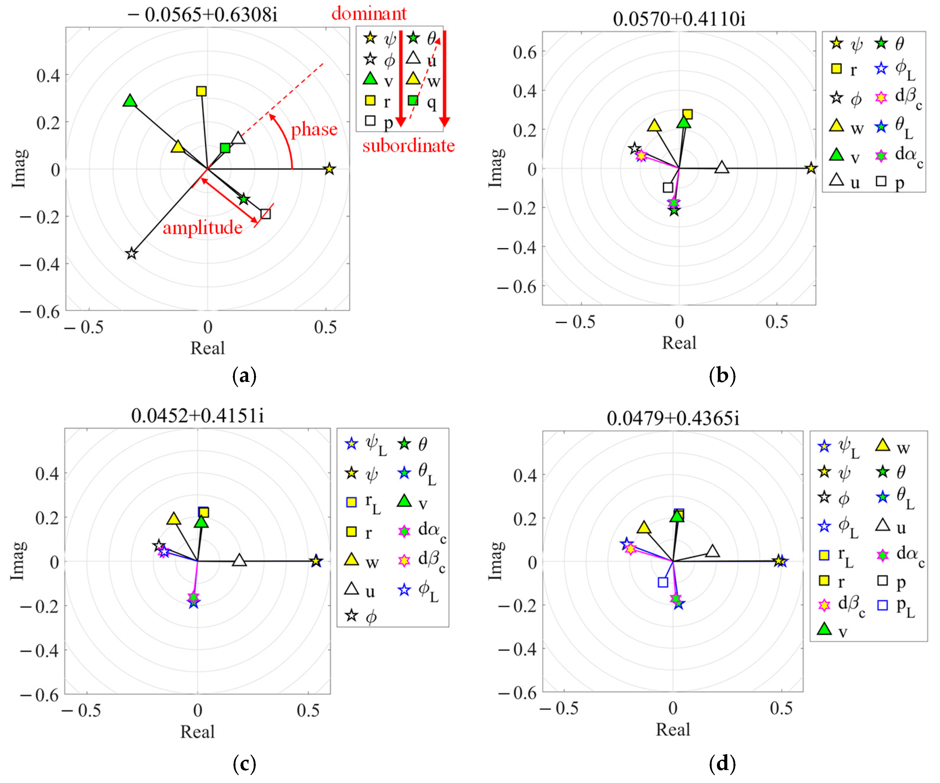
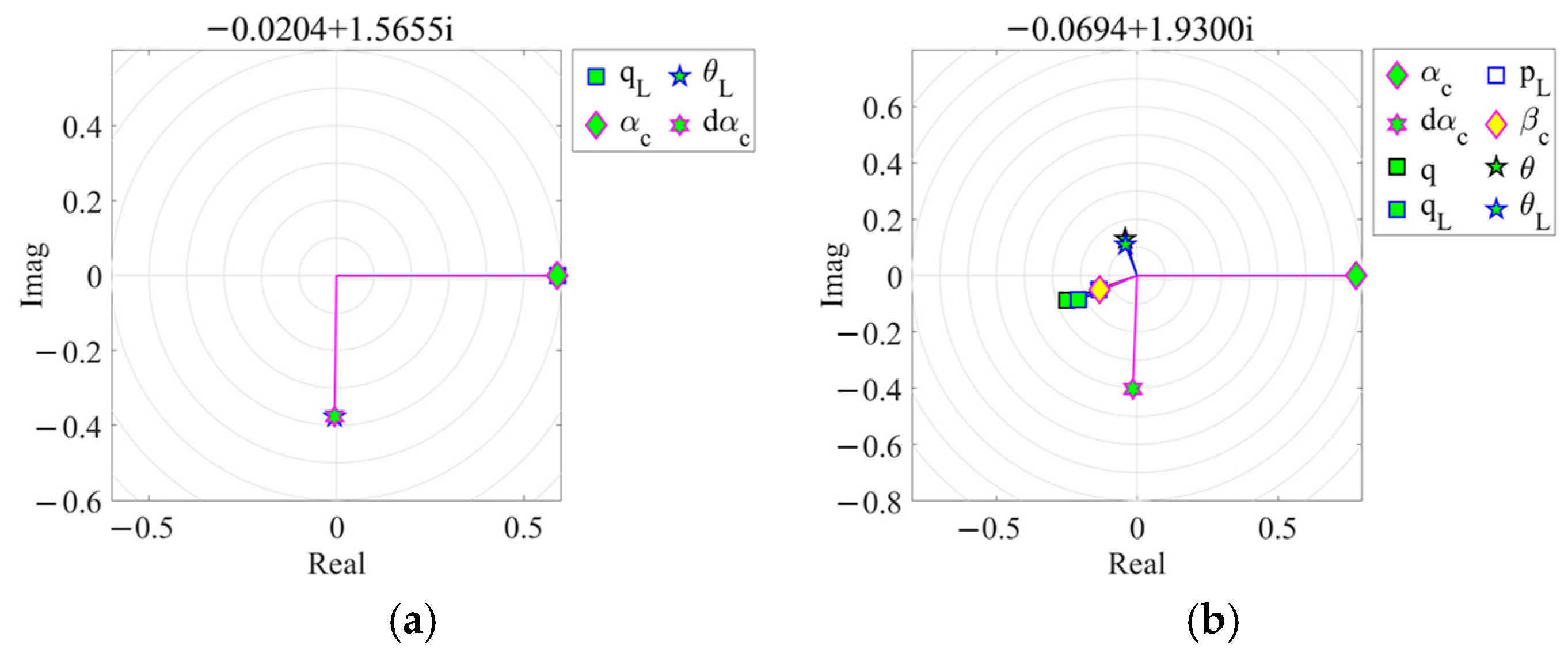
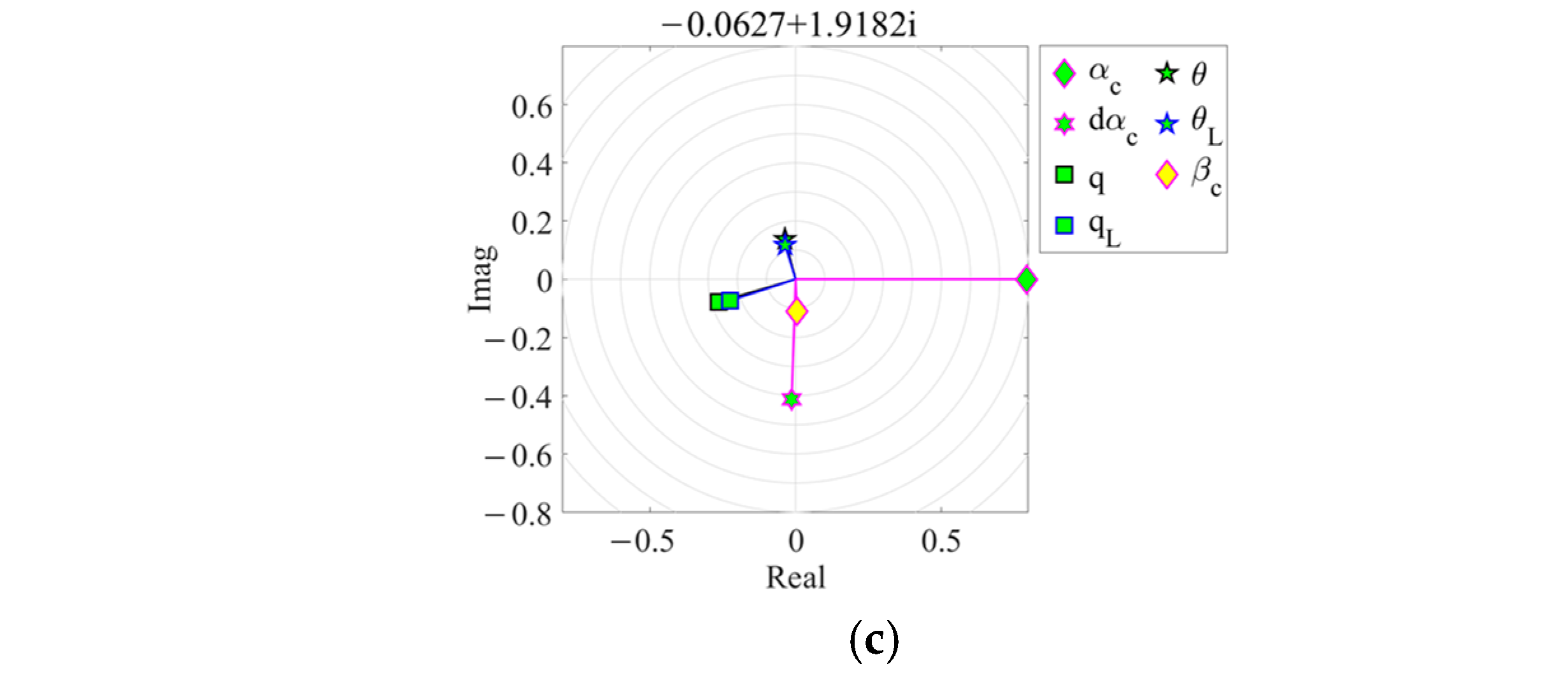
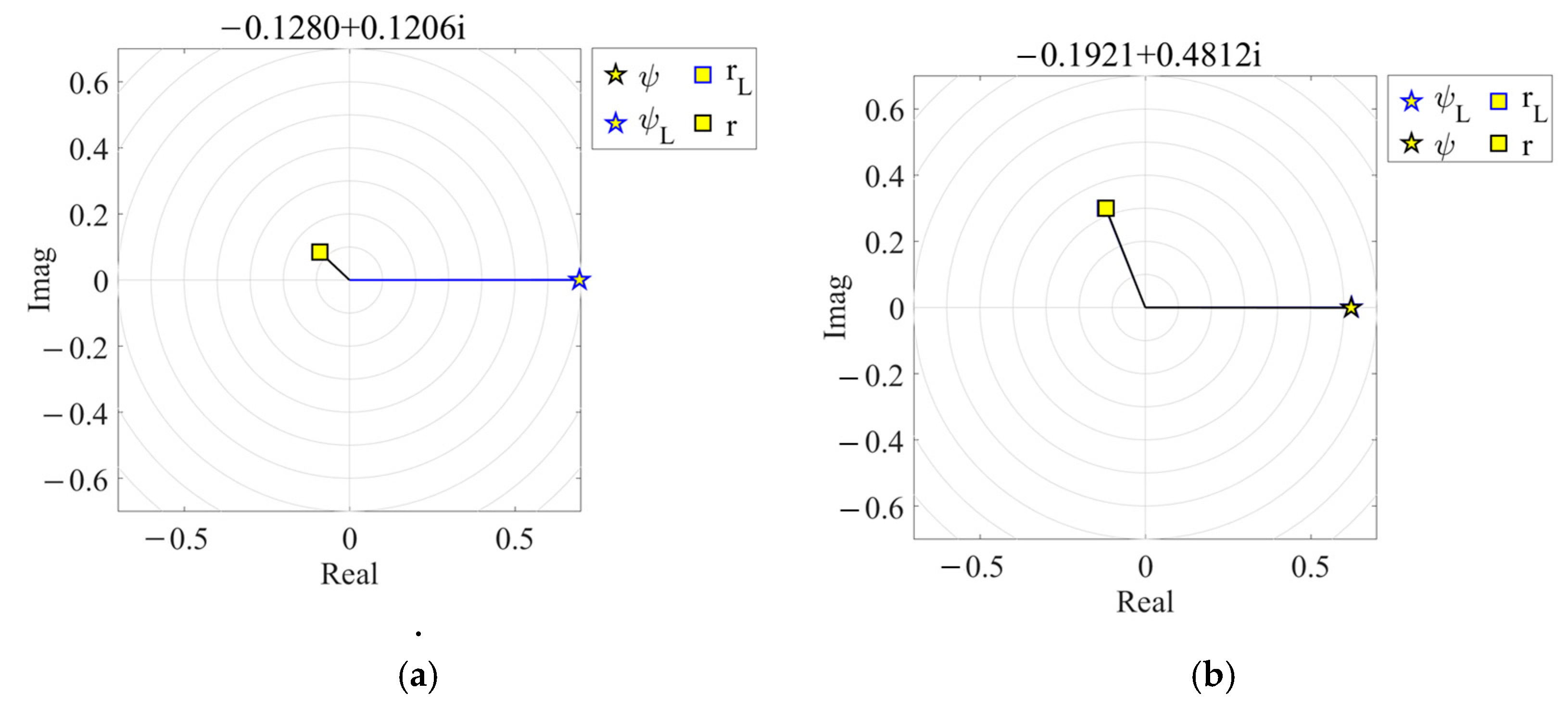
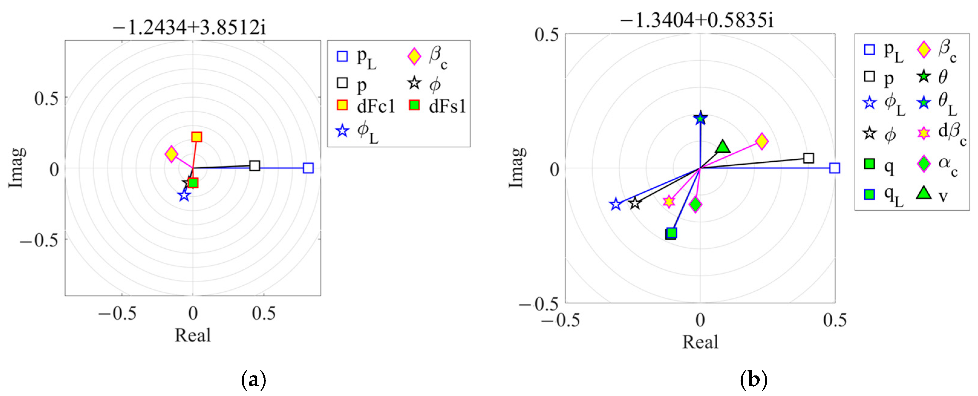
Figure 10 illustrates the Dutch roll mode eigenvectors for four cases. The complex number on the top of each eigenvector figure is the corresponding eigenvalue. Symbols in the legend denote main state variables of the HSLS that describes the eigenvector shape. The top left state variable is the most dominant variable, since it has the largest amplitude, while the bottom right state variable is the most subordinate variable. It should be noted that state variables with amplitudes less than 0.1 are omitted.
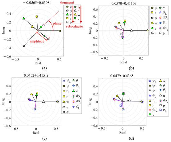
Figure 10.
Dutch roll mode eigenvectors of four cases in hover. (a) No load. (b) 1-point. (c) 2-point. (d) 4-point.
It can be observed from Figure 10 that the eigenvector shape changes significantly when carrying a slung load, but the eigenvectors for the three sling configurations are similar. When carrying a slung load, the helicopter’s yaw motion ( and ) becomes more prominent in the Dutch roll mode, while the helicopter’s lateral motion (, , and ) becomes subordinate.
This phenomenon occurs because the gross weight of the HSLS is distributed between the helicopter and the load when carrying a slung load. As the helicopter becomes lighter while being connected to a heavy slung load, its lateral motions are influenced by the lateral swing motions of the load ( and ). As shown in Figure 10b, , , have the same phase, resulting in a decrease in the amplitude of helicopter lateral motions and an increase in load lateral swing motions. This indicates that the helicopter’s lateral motions are strongly coupled with the load’s lateral swing motion, eventually exhibiting synchronized motion in the Dutch roll mode.
Eigenvectors for the three sling configurations are similar because the helicopter’s yaw motion does not couple with the load’s yaw motion ( and ) in the 1-point case. In the 2-point and 4-point cases, although the helicopter and load yaw motions are coupled, the frequency of the load yaw oscillation is far from the helicopter’s yaw motion frequency, resulting in the same amplitudes and phases for both the helicopter’s yaw motions and the load’s yaw motions. In other words, the load’s yaw motions follow those of the helicopter in the Dutch roll mode, also exhibiting synchronized motion. Thus, while multiple sling configurations can result in additional yaw moment to the helicopter, this effect is secondary compared to the mass distribution between the helicopter and the load.
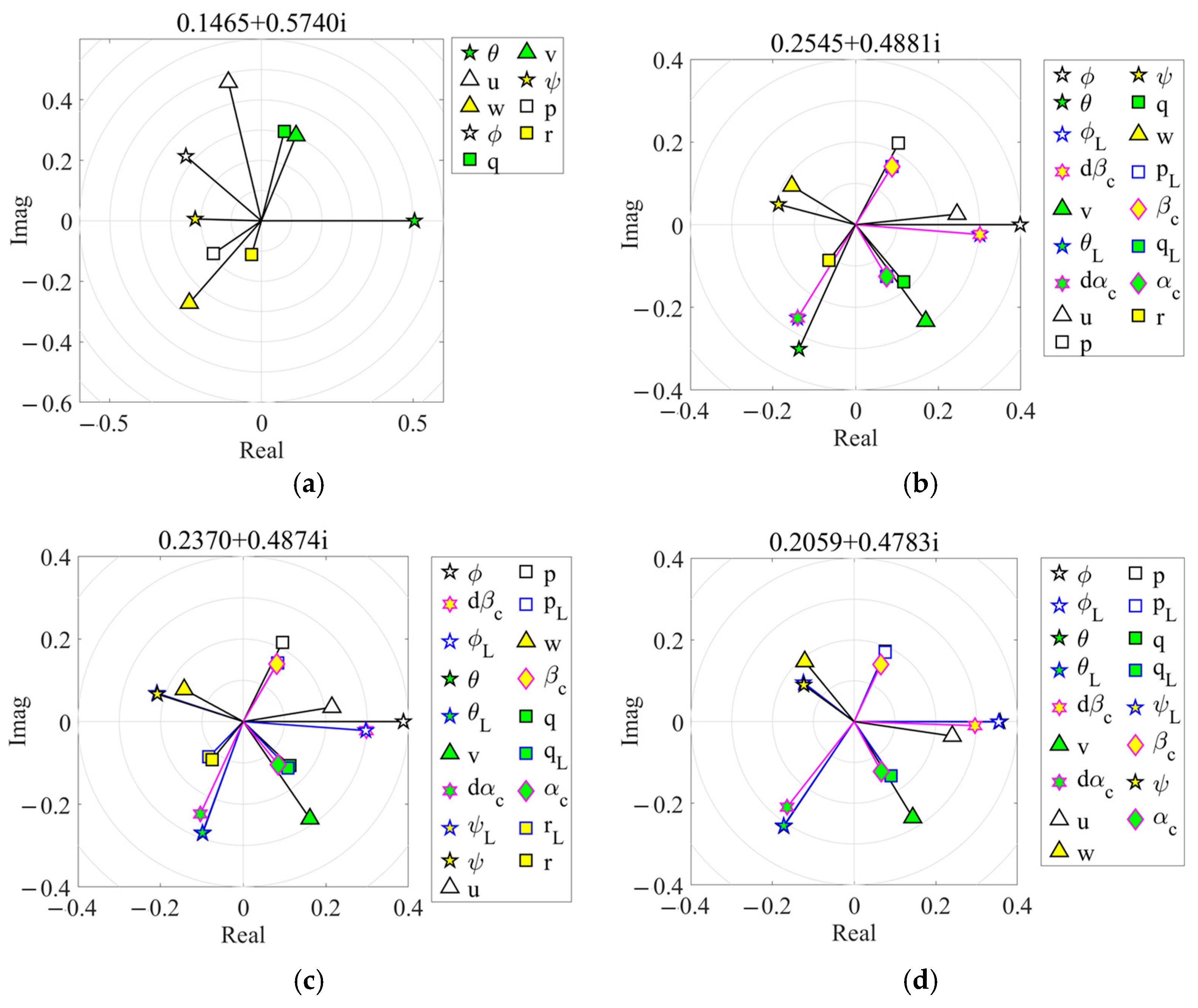
Figure 11 illustrates the phugoid mode eigenvectors for four cases. It is evident that carrying a slung load significantly affects the mode eigenvector, regardless of the sling configuration used. Taking the 1-point configuration as an example, by comparing the dominant motions in Figure 11a,b, it is observed that helicopter roll and pitch motions ( and ) have similar amplitudes when carrying a slung load. This indicates that the helicopter’s lateral motions are more strongly coupled with longitudinal motions, which deteriorates the stability of both the Dutch roll and phugoid modes.
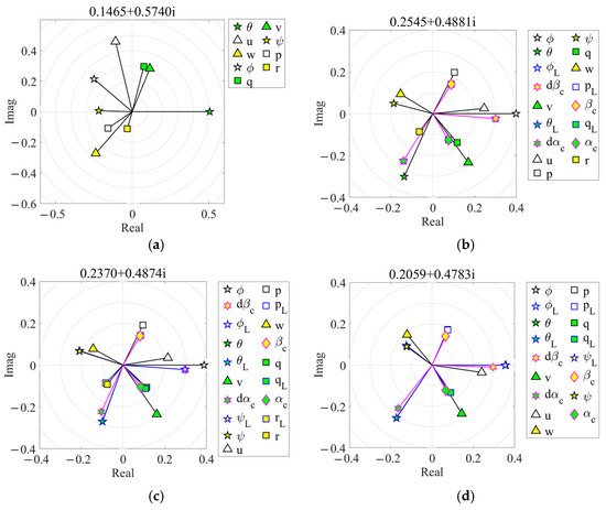
Figure 11.
Phugoid mode of various HSLS configurations in hover. (a) No load. (b) 1-point. (c) 2-point. (d) 4-point.
Similar observations as the Dutch roll mode can be obtained for 1-point, 2-point, and 4-point configurations. Load yaw motions ( and ) appear in the mode eigenvector and have almost the same amplitude and phase as the helicopter’s yaw motions ( and ), indicating synchronized yaw motions of the helicopter and the load.
Figure 12 presents the eigenvalues of the slung load modes for four cases and various speeds (0–23 m/s), along with the extended limit boundaries for oscillatory modes defined by ADS-33E. As speed increases from hover to 45 knots, the frequency of the load yaw oscillation mode increases, while its damping decreases. The 1-point configuration exhibits significant sensitivity to speed and becomes unstable as speed increases. In contrast, the 2-point and 4-point configurations demonstrate less pronounced sensitivity and remain neutrally stable.
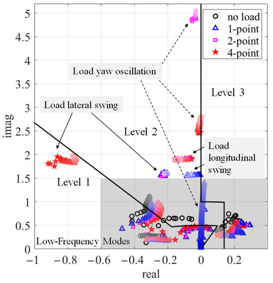
Figure 12.
Slung load mode eigenvalues of 4 cases and various speeds.
This phenomenon can be attributed to the inherent instability of slung load bluff-body aerodynamics, which intensifies with increased speed. The 1-point configuration fails to provide sufficient yaw recovery torque, unlike the 2-point and 4-point configurations. As a result, the yaw oscillation mode in the 1-point configuration is dominated by unstable aerodynamic yaw moments. However, while the yaw recovery torque in the 2-point and 4-point configurations increases the frequency of yaw oscillations, it does not significantly enhance damping. Consequently, persistent load yaw oscillations may still occur in the 2-point and 4-point configurations.
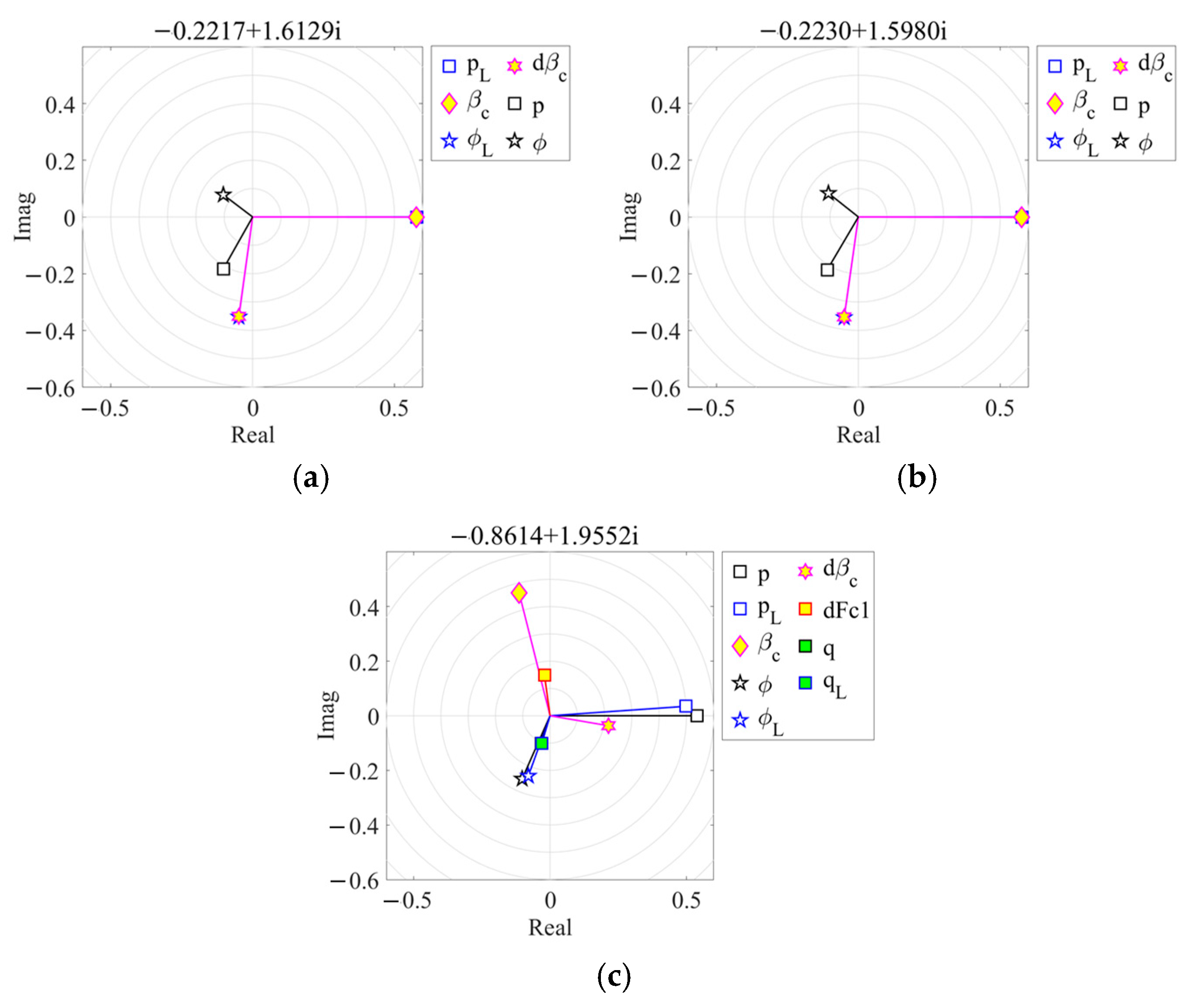
For load swing modes, the swing frequency of the load remains relatively unchanged as speed increases. However, multiple-point configurations exhibit a higher swing frequency compared to the 1-point configuration. The damping of the load’s longitudinal swing mode increases with speed, while the damping of the lateral swing mode decreases slightly. For the 4-point configuration, the stability of the load lateral swing mode is significantly enhanced to reach the Level 1 region. The stability of the load longitudinal swing mode shows slight improvement for the 2-point and 4-point configurations, but it remains within the Level 2 region. The above observations can be elucidated by examining the eigenvectors of the load lateral and longitudinal swing modes, as depicted in Figure 13 and Figure 14.
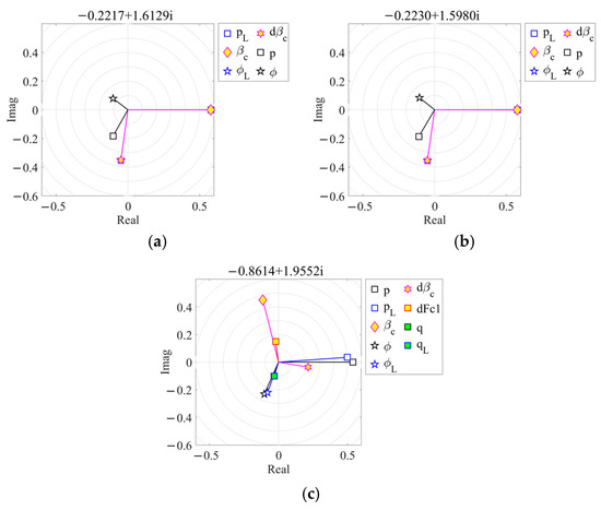
Figure 13.
Load lateral swing mode eigenvectors of 3 sling configurations in hover. (a) 1-point. (b) 2-point. (c) 4-point.
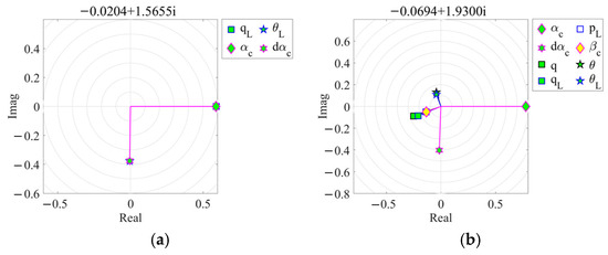
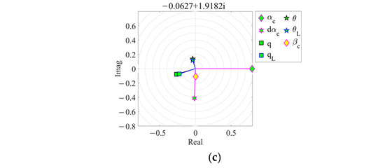
Figure 14.
Load longitudinal swing mode eigenvectors of 3 sling configurations in hover. (a) 1-point. (b) 2-point. (c) 4-point.
As illustrated in Figure 13, the eigenvectors for the 1-point and 2-point configurations are nearly identical, whereas significant changes are observed in the 4-point configuration. The eigenvector of the 4-point configuration reveals that the helicopter’s roll motions ( and ) have the same phase with the slung load’s roll motions ( and ). Additionally, the first-order cosine term of the rotor flapping rate (dFc1) appears in the 4-point configuration and has the same phase as the load’s lateral swing angle ().
This indicates that the load lateral swing mode involves significant coupling between the load’s lateral swing motion and the helicopter’s roll motion. When a multiple-point configuration is employed, an additional swing recovery moment arises due to the varying tensions in the left and right slings, which can be interpreted as an increase in stiffness. As a result, the frequency of the load’s lateral swing mode is increased. Furthermore, as the slung load swings from left to right, the helicopter encounters a significant roll moment caused by the differing tension forces in the left and right hooks, leading to a corresponding roll motion in the helicopter. The main rotor, mirroring the helicopter’s roll motion, generates a substantial recovery moment due to its flapping dynamics. This recovery moment enhances the helicopter’s roll damping, which, in turn, further improves the damping of the load’s swing. Consequently, the stability of the load’s lateral swing mode is significantly enhanced in the 4-point configuration.
In contrast, Figure 14 shows the eigenvectors of the load longitudinal swing mode. Although the helicopter’s pitch motions ( and ) and the load’s pitch motions ( and ) have the same phase, the amplitudes of and are much smaller due to the helicopter’s significantly larger pitching inertia compared to its roll inertia. The frequency of the load’s longitudinal swing mode increases due to the coupled interaction between the helicopter’s pitch motion and the load’s longitudinal swing motion. However, the smaller amplitude of the helicopter’s pitch motion results in less effective damping from rotor flapping dynamics compared to roll motion. Consequently, rotor flapping motion does not appear in the eigenvector of the load longitudinal swing mode, which is different from lateral swing. Therefore, the stability of the load longitudinal swing is slightly improved when a multiple hook point sling configuration is adopted.
3.2. Attitude and Heading Changes
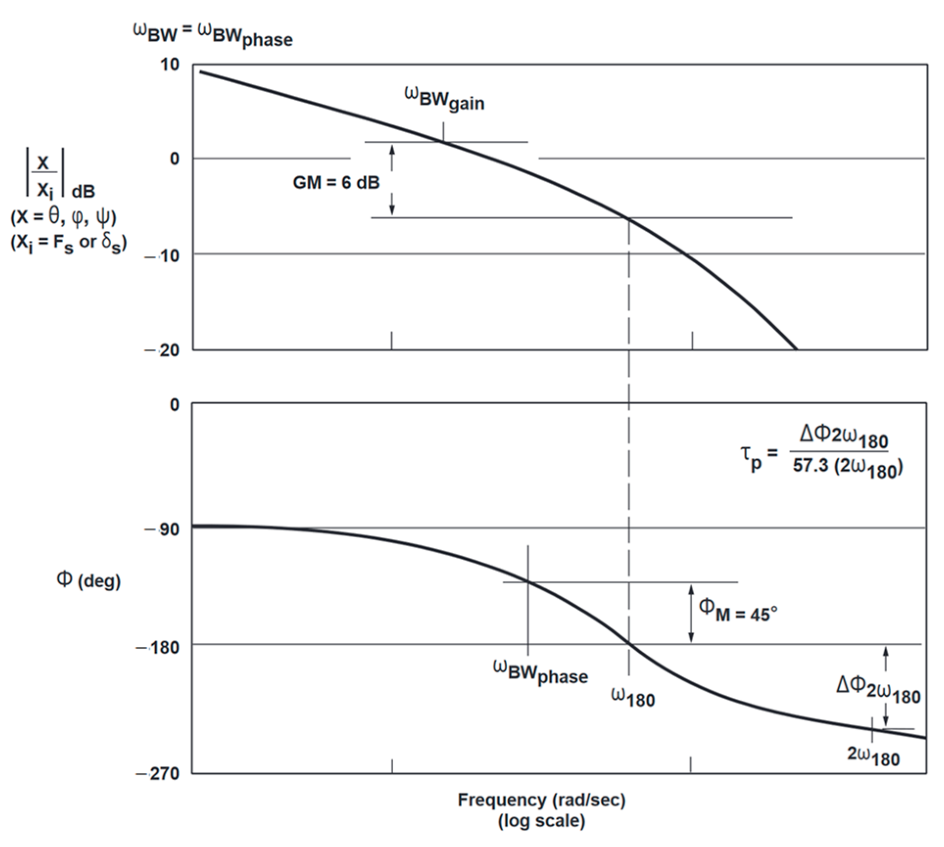
Handling quality requirements concerning attitude and heading changes are based on the helicopter’s on-axis frequency response. Based on the linearized HSLS model, the helicopter’s on-axis frequency response can be obtained by drawing the bode plot of the transfer function from control input to attitude and heading changes. According to the definitions in ADS-33E, bandwidth, , and phase delay, , at every trimmed state can be obtained, as shown in Figure 15. At last, the obtained bandwidths and phase delays are plotted along with the attitude and heading change boundaries specified in ADS-33E.
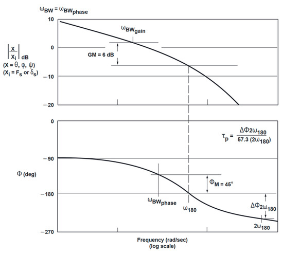
Figure 15.
Definition of bandwidth and phase delay in ADS-33E [3].
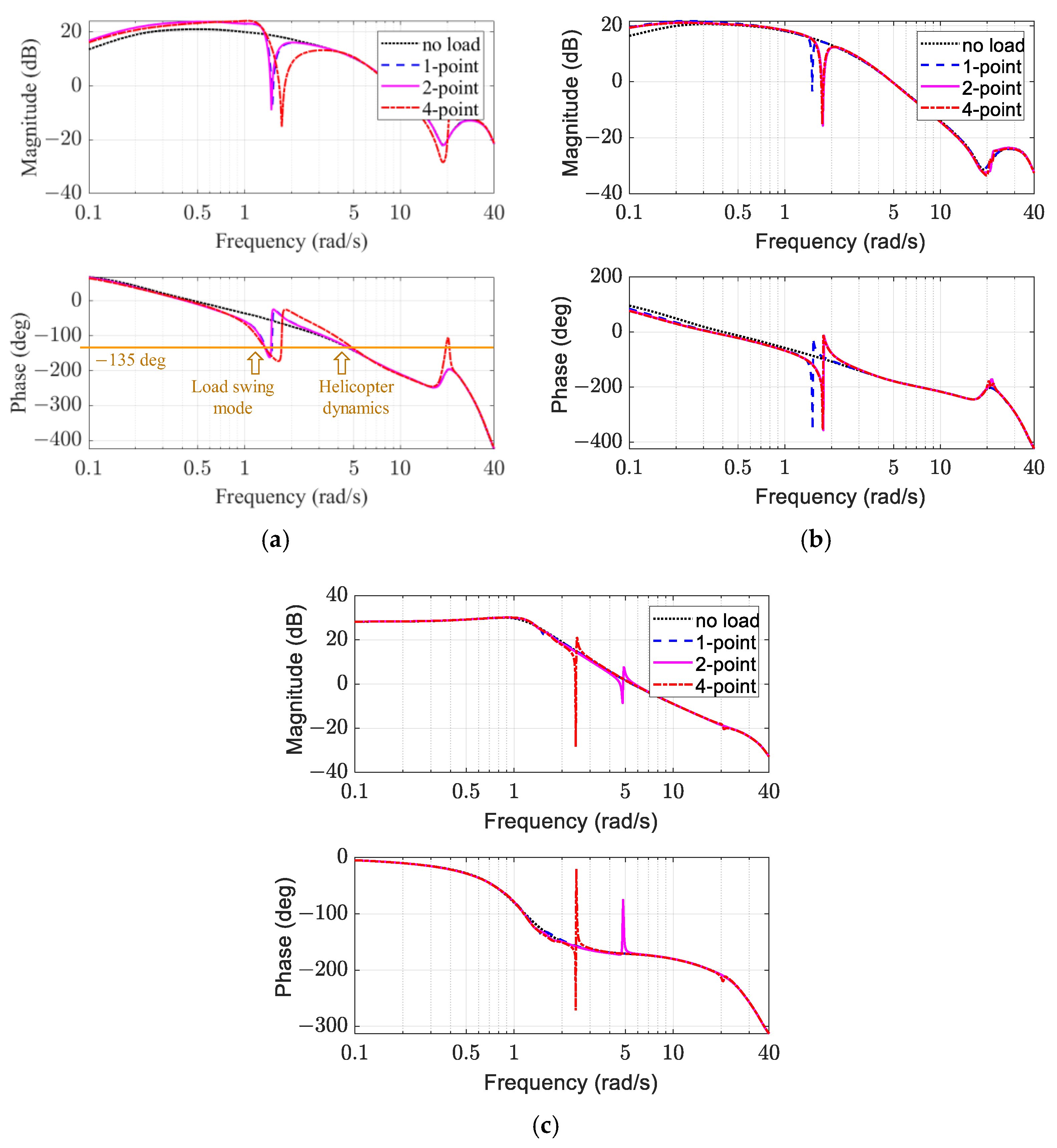
Figure 16 illustrates the on-axis frequency responses of attitude and heading changes: roll, pitch, and yaw. To mitigate the effects of the unstable Dutch roll and phugoid modes, a low-gain state feedback controller is employed [25]. These frequency responses are obtained by first linearizing the HSLS model at hover and then calculating the on-axis transfer function based on the linearized HSLS model. This approach is more effective than the system identification method used for HSLS validation in Section 2.3, as it improves frequency resolution while minimizing the negative effects of noise.
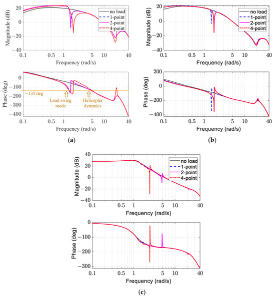
Figure 16.
On-axis frequency response characteristics in hover. (a) Roll response. (b) Pitch response. (c) Yaw response.
It can be observed from Figure 16a,b that roll and pitch responses exhibit significant magnitude notches and phase lags within the frequency range of 1–2 rad/s, which are associated with load swing modes. The roll responses for the 1-point and 2-point configurations are similar, whereas the 4-point configuration exhibits a higher frequency but larger magnitude notch. This difference is due to the higher frequency of the load lateral swing mode in the 4-point configuration. Conversely, the pitch responses for the 2-point and 4-point configurations are similar, whereas the 1-point configuration demonstrates a lower frequency, attributable to the smaller frequency of the load longitudinal swing mode in the 1-point configuration. The magnitude notch and phase lags in the roll response affect a wider frequency range than those in the pitch response. However, phase lags in the pitch response are more severe than in the roll response, exceeding −360 degrees. Additionally, multiple-point configurations affect a broader frequency range and introduce a deeper magnitude notch than single-point configurations due to the stronger coupling between the helicopter and the slung load.
Yaw responses for the 2-point and 4-point configurations exhibit sharp resonant and anti-resonant peaks at the frequency of the load yaw mode, whereas the yaw response for the 1-point configuration is similar to the no-load condition. This indicates that when multiple point configurations are adopted, the helicopter yaw response can resonate with the load yaw motion at certain frequencies. However, the affected frequency range is narrow.
It should be noted that the roll response of the 4-point configuration exhibits significant resonant and anti-resonant peaks around 20 rad/s, corresponding to the frequency of the sling stretching mode. This phenomenon is primarily due to the coupling of the helicopter’s roll motion with the sling’s stretching motion in 4-point configurations. This coupling exhibits a small damping ratio, resulting in a pair of poles and zeros with similar frequencies and small damping ratios in the roll response. This difference arises because the helicopter’s roll motion is coupled with the sling’s stretching motion in the 4-point case, whereas it is not in the other sling configurations due to the helicopter’s pitch and yaw inertia being considerably larger than its roll inertia. However, since the frequency is around 20 rad/s, its effects can be negligible for heading changes.
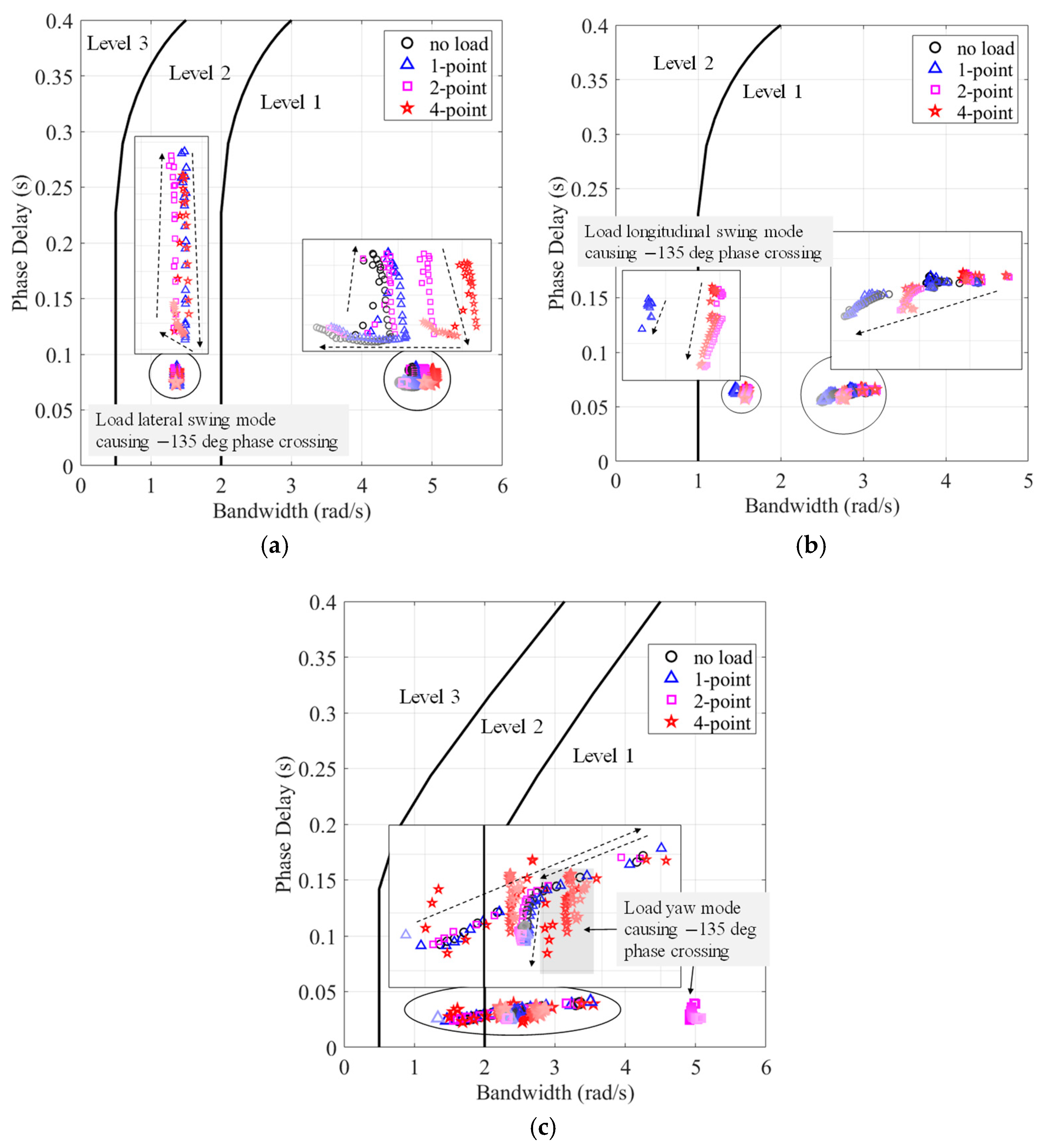
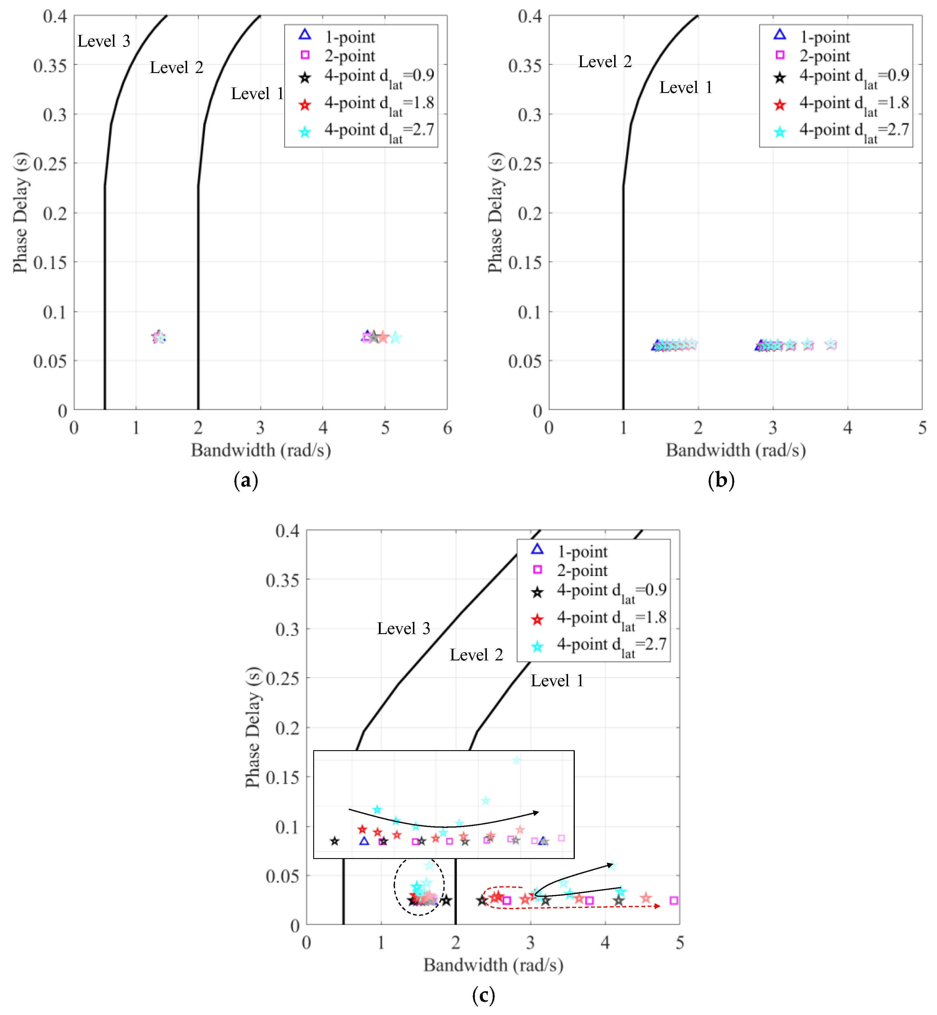
Figure 17 illustrates the criteria for helicopter HQs of attitude and heading changes for various configurations and speeds. These criteria use bandwidth and phase delay as defined in ADS-33E. It can be observed that carrying a slung load adds an additional bandwidth value with a much lower frequency (about 1.5 rad/s). This is caused by the additional −135 degree crossing of the phase curve at the load swing mode frequency, as shown in Figure 16a. The other bandwidth with a higher frequency (about 3–5 rad/s) is caused by helicopter dynamics.
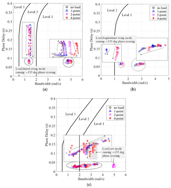
Figure 17.
Bandwidth and phase delay for various sling configurations and speeds. (a) Roll. (b) Pitch. (c) Yaw.
In Figure 17a, the roll bandwidth caused by helicopter dynamics increases as the number of hook points increases. This is because multiple sling configurations can increase helicopter roll motion stiffness by adding an additional roll recovery moment. As speed increases, the roll bandwidth remains constant at first, while the phase delay of the roll response initially increases and then decreases. Eventually, the phase delay stabilizes while the bandwidth decreases. Conversely, the roll bandwidth caused by the load lateral swing mode shows little change, and the phase delay also exhibits similar characteristics. The HQ of roll attitude changes determined by helicopter dynamics remains in the Level 1 region, while that determined by the load lateral swing mode stays in the Level 2 region.
In Figure 17b, the pitch bandwidth caused by helicopter dynamics also increases as the number of hook points increases, but this increase is more significant than in roll. As speed increases, the pitch bandwidth and phase delay decrease. At certain speeds, the phase curve of the 1-point configuration crosses −135 degrees at the load longitudinal swing mode frequency, bringing an additional lower bandwidth. However, since the boundary of pitch bandwidth is lower than roll bandwidth, the HQ remains in the Level 1 region.
In Figure 17c, the yaw bandwidth caused by helicopter dynamics varies significantly with respect to speed. It increases from 1.5 rad/s to 3.5 rad/s as speed increases initially. Then, it decreases and stabilizes at 2.5 rad/s as speed further increases. Carrying a slung load has negligible effects on yaw bandwidth. This is because the load yaw motion-affected frequency range is narrow and usually larger than the yaw bandwidth determined by helicopter dynamics.
3.3. Pitch and Roll Response to Externally Slung Loads
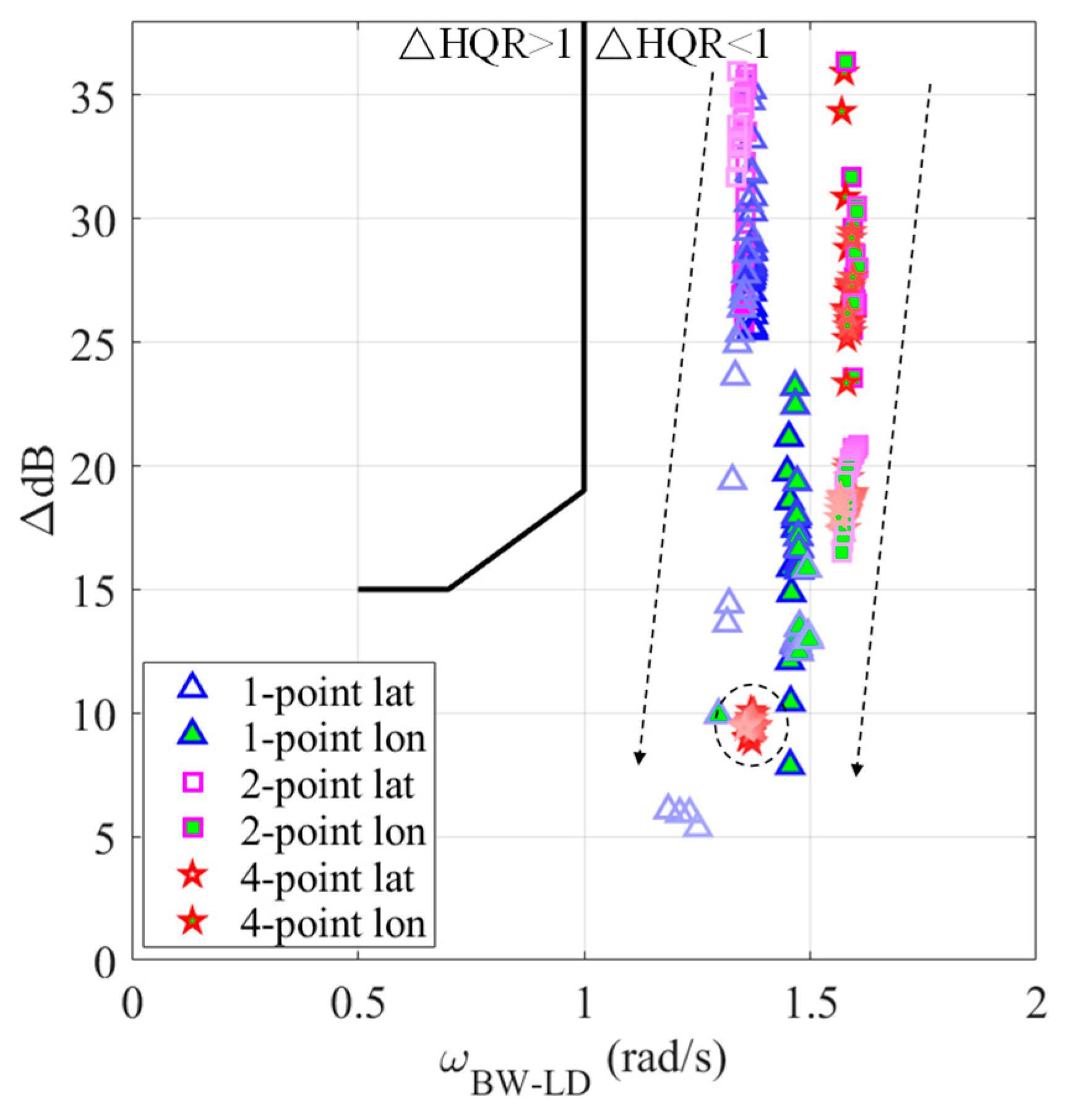
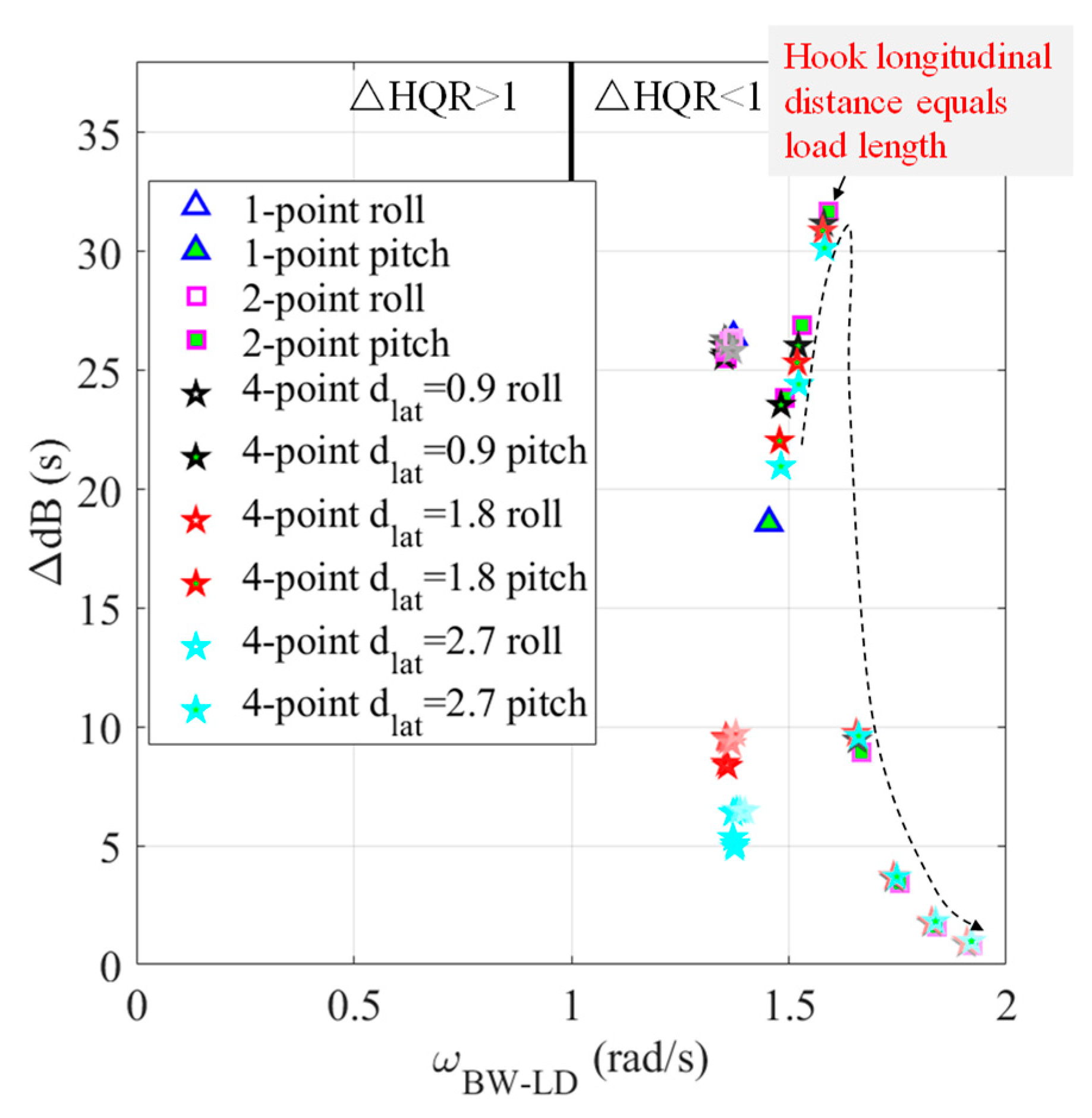
In the proposed revisions of the updated HQ specification ADS-33F [8], a new criterion, denoted as , is introduced to assess the degradation of handling quality ratings when carrying a slung load compared to the unloaded case. This metric is based on the load bandwidth () and delta dB () of the helicopter’s roll and pitch frequency responses. is defined as the lesser of the −135 degree crossing or the frequency of minimum phase due to the load mode. represents the deformation of the magnitude curve caused by the externally slung load, which is estimated from the centroid of the magnitude notch area in the critical frequency range of . The and of each trimmed state of the HSLS are plotted along with the boundaries specified in Ref. [8] to evaluate the HQ degradation when carrying a slung load.
Figure 18 presents the for various configurations and speeds. Markers with a white face represent the of the lateral channel, whereas markers with a green face represent the longitudinal channel. It can be observed from Figure 13 that the longitudinal channel exhibits a larger than the lateral channel because the longitudinal load swing mode has a higher frequency than the lateral swing mode. As speed increases, the for both channels decreases, while the shows minimal changes.
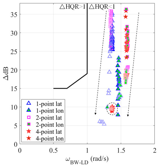
Figure 18.
for various sling configurations and speeds.
For the lateral channel, the 4-point configuration demonstrates the best performance for , as the remains below 10 dB with increasing speed. The 1-point configuration is the most sensitive to speed, with its varying from 35 to 5 as speed increases. For the 2-point configuration, the decreases from 35 to 25 as speed increases, indicating less sensitivity to speed compared to the 1-point configuration. Thus, the 4-point configuration is the optimal choice to minimize the lateral channel , while the for the 1-point and 2-point configurations can be improved with increasing speed.
For the longitudinal channel, the decreases as speed increases for all sling configurations. However, the of the 1-point configuration is generally lower than those of the 2-point and 4-point configurations. Therefore, the 1-point configuration is the optimal choice for minimizing the of the longitudinal channel, while the 2-point and 4-point configurations exhibit nearly identical performance.
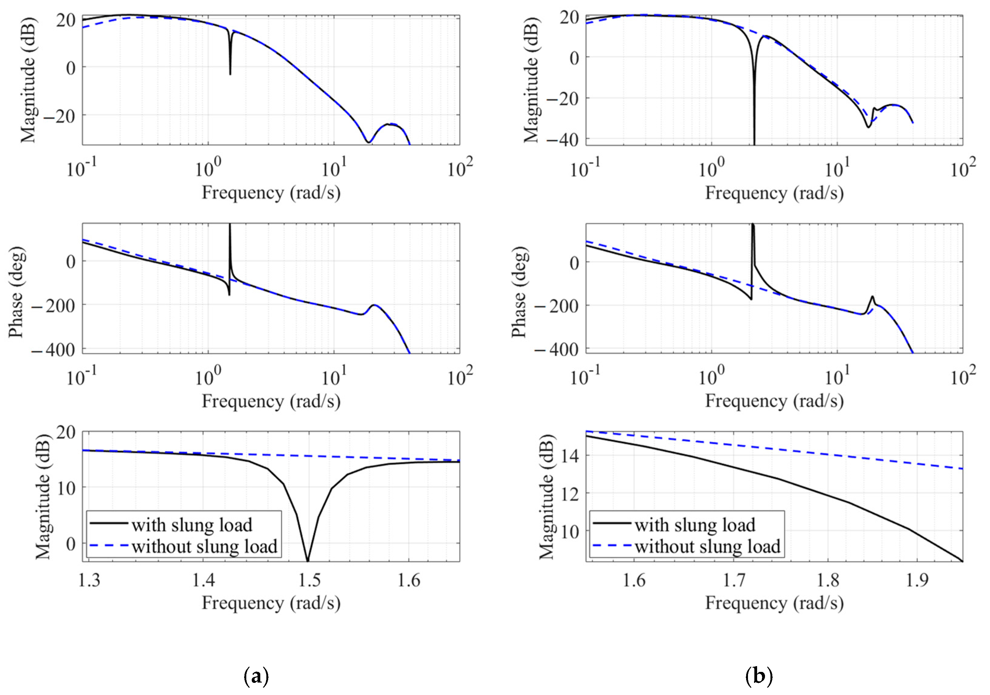
It should be noted that the 4-point sling configuration introduced a deeper magnitude notch in Figure 16a, while Figure 18 indicates a smaller . This is because, since is the lesser of the −135 deg crossing or frequency of the minimum phase due to the load swing mode, the magnitude notch frequency is distant from the frequency range of . For example, Figure 19 shows the pitch response of 1-point configuration and 2-point configuration with a large hook distance (4.8 m). The third figure is a closed view of the magnitude curve within the frequency range of . As shown in Figure 19b, it can be observed that the magnitude notch is distant from for the 2-point configuration with a large hook distance. As a result, the centroid and are smaller, indicating a mitigation of HQ degradation.
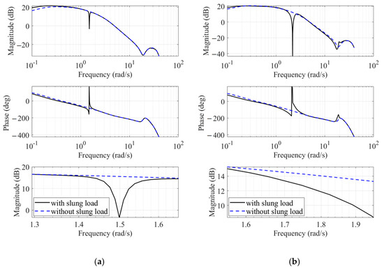
Figure 19.
Comparison of pitch responses for 1-point and 2-point configurations in hover. (a) 1-point configuration. (b) 2-point configuration with 4.8 m hook longitudinal distance.
3.4. Effects of Hook Distance
In multiple-point configurations, the hook distance is a key design parameter. In this research, the basic lateral and longitudinal hook distances are the same as the width and length of the rectangular CONEX container. This section analyzes the effects of lateral and longitudinal hook distances on the HQ requirements mentioned above. From the previous analysis, we found that hover is the most critical flight condition for hover and low-speed HQ since increasing speed benefits load swing stability when the speed is less than 23 m/s. Therefore, hover is selected as the crucial state to analyze the effects of hook distance.
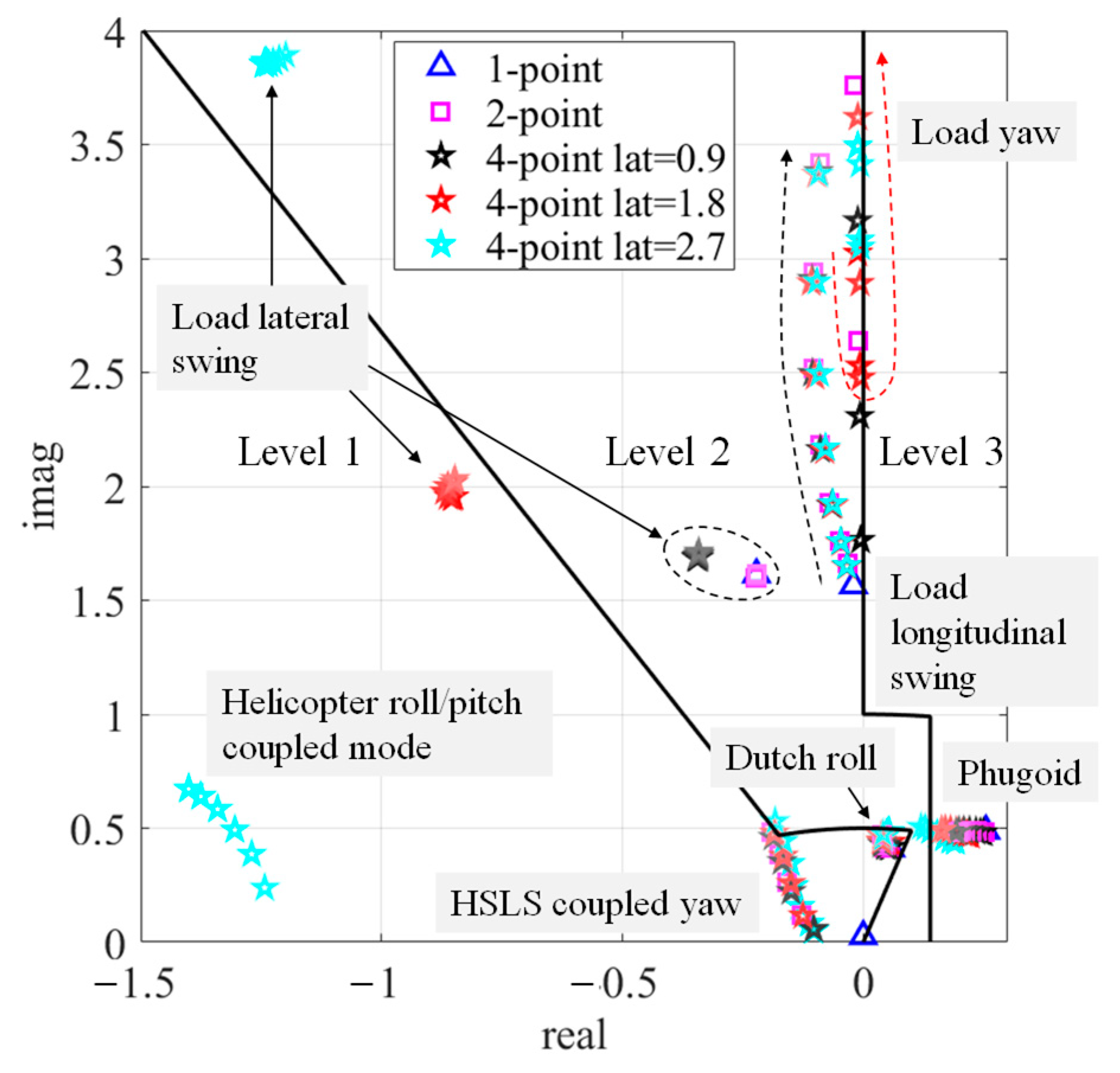
Figure 20 shows the low-frequency oscillation mode eigenvalues for various hook distances in hover. As the longitudinal hook distance increases from 1.2 to 4.8 m, the color of the markers fades. Three lateral hook distances of 0.9, 1.8, and 2.7 m are also used. The 1-point configuration is selected as the baseline.
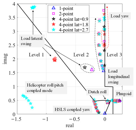
Figure 20.
Low-frequency oscillation mode eigenvalues of various hook distances in hover.
It can be observed that hook distances have minimal effects on the Dutch roll mode, while phugoid mode stability improves with either a larger longitudinal or larger lateral hook distance. The frequency of the load longitudinal swing mode increases as the longitudinal hook distance increases. Similarly, as the lateral hook distance increases, the frequency of the load lateral swing mode increases. The damping ratio of the load lateral swing mode is highest when the lateral hook distance matches the width and length of the rectangular CONEX container.
Load yaw mode exhibits different characteristics. For the 2-point configuration, the frequency of the load yaw mode increases as the longitudinal hook distance increases. For the 4-point configuration, as the lateral hook distance increases, the yaw moment provided by the 4-point sling configuration becomes larger. However, as the longitudinal hook distance increases, the load yaw mode of the 4-point configuration shows a decrease in frequency followed by an increase. This indicates that the yaw moment provided by the 4-point sling configuration can be magnified if the longitudinal hook distances are either smaller or larger than the width and length of the rectangular CONEX container.
Except from the above modes, if the longitudinal hook distance increases to larger than the length of the rectangular CONEX container in 2-point and 4-point configurations, the HSLS coupled yaw mode emerges. If the lateral hook distance increases to 2.7 m, the helicopter roll/pitch coupled mode appears.
Figure 21 shows the eigenvectors of the helicopter slung load system couple yaw mode in hover. When longitudinal hook distance increases from 3.1 m to 4.8 m, the mode eigenvector has a larger amplitude of yaw rate ( and ). Figure 22 shows the eigenvectors of the load lateral swing mode and the helicopter roll/pitch coupled mode when the hook lateral distance equals 2.7 m. It can be observed that the load lateral swing mode involves helicopter roll motion while the helicopter roll/pitch coupled mode involves load lateral swing motion. Figure 21 and Figure 22 both indicate stronger couplings between helicopter angular motions and load swing motions, leading to the emergence of the additional coupled oscillation mode.
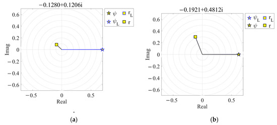
Figure 21.
HSLS couple yaw mode eigenvector of different longitudinal hook distances in hover. (a) 3.1 m. (b) 4.8 m.
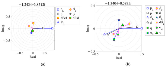
Figure 22.
Coupled mode eigenvectors of large hook lateral distance (2.7 m) in hover. (a) Load lateral swing mode. (b) Helicopter roll/pitch coupled mode.
Figure 23 shows bandwidth and phase delay for various hook distances in hover. As the hook longitudinal distance increases, the markers fade. It can be observed that increasing the hook longitudinal distance has few effects on the roll channel while it is beneficial for the pitch bandwidth. Conversely, increasing the hook lateral distance has few effects on pitch channel while it benefits the roll bandwidth. Yaw bandwidth is affected by both longitudinal and lateral hook distance. A larger lateral hook distance has advantages for yaw bandwidth. However, the yaw bandwidth decreases then increases as the longitudinal hook distance increases, indicating bandwidth is the smallest when the longitudinal distance is equal to the load length.
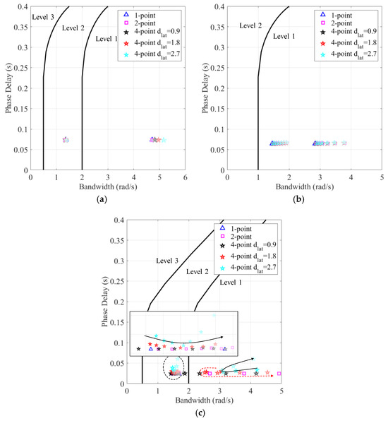
Figure 23.
Bandwidth and phase delay for various hook distances in hover. (a) Roll. (b) Pitch. (c) Yaw.
Figure 24 shows for various hook distances in hover. A larger lateral hook distance can decrease of the roll channel. However, of the pitch channel increases then decreases as the longitudinal hook distance increases, indicating the worst case is when the longitudinal distance equals the load length. This is because, as the hook distance increases, the magnitude notch becomes deeper and the notch frequency higher due to the stronger coupling between the helicopter motions and slung load motions. The magnitude notch deepens as the hook distance approaches the load length, while the notch frequency remains within the critical frequency range of , leading to maximum . As the hook distance increases further, the notch frequency continues to rise, moving further away from the critical frequency range, which results in a decrease in . In practice, since the ability to mitigate HQ degradation by reducing the hook’s longitudinal distance is limited, a hook distance equal to twice the length of the slung load is recommended.
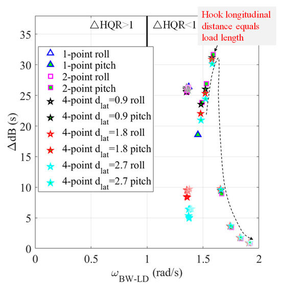
Figure 24.
for various hook distances in hover.
The longitudinal hook distance has few effects on the roll channel while the lateral distance has slight good effects on pitch channel. of the roll channel decreases significantly when the lateral hook distance is smaller than the slung load width. However, further increasing the lateral distance shows less significant effects.
4. Conclusions
This paper assesses the handling qualities of helicopters with slung load systems using multi-point sling configurations. We introduce a computer-oriented generalized method for establishing a sling system model that connects the helicopter and the load. Compared to existing modeling methods, this approach offers a more streamlined and automated modeling process, along with a clear Newtonian formulation for analyzing inherent dynamic couplings. The HQ requirements related to the stability of oscillatory modes, attitude and heading changes, and pitch (roll) responses to externally slung loads are evaluated for HSLS with 1-point, 2-point, and 4-point sling configurations. Modal analysis was conducted to elucidate the coupled dynamics of various sling configurations and the effects of hook distance. Furthermore, we discuss the new criterion for slung load operations in alignment with ADS-33F. The findings clearly highlight the differences among various sling configurations, providing valuable recommendations for practical sling configuration selection. The primary conclusions are as follows:
(1) The multiple-point sling configuration intensifies the coupling between helicopter roll/pitch motions and load swing motions, resulting in an increase in both the frequency and stability of load swing modes. The rise in load swing frequency is attributed to the different tensions in the left/right and forward/aft slings, which provide additional swing stiffness. The improvement in load swing stability is due to the main rotor generating a significant damping moment, caused by flapping dynamics, when the helicopter exhibits roll/pitch motions. However, it should be noted that the enhancement in the stability of the load’s longitudinal swing mode is less pronounced than that of the lateral swing mode. This difference arises because the helicopter’s pitch motion has a smaller amplitude compared to the roll motion, due to the significantly greater pitch inertia relative to roll inertia.
(2) While multiple-point sling configurations can enhance the bandwidth of helicopter dynamics, they also exacerbate the magnitude notch in the helicopter’s roll and pitch responses by introducing a deeper notch and impacting a broader frequency range. This is due to the stronger coupling between helicopter motions and slung load motions as the hook point number increases. However, the resulting HQ degradation of multiple-point configurations is less severe than in the 1-point configuration because the frequency range affected by the multiple-point sling configuration lies outside the critical frequency range near the load bandwidth. Consequently, the helicopter and load can move as a unified system without load swing oscillations within the critical frequency range.
(3) A longitudinal hook distance equal to the length of the slung load should be avoided, as it leads to the most severe HQ degradation. This occurs because, as the hook distance increases, the magnitude notch deepens and the notch frequency rises due to the stronger coupling between helicopter motions and slung load motions. The magnitude notch becomes more pronounced as the hook distance approaches the load length, while the notch frequency remains within the critical frequency range near the load bandwidth, resulting in maximum HQ degradation. As the hook distance increases further, the notch frequency continues to rise, moving further away from the critical frequency range, which results in a decreased HQ degradation.
(4) In practice, it is recommended to use a 4-point configuration with lateral and longitudinal hook distances equal to twice the width and length of the slung load. Load swing stability can be enhanced significantly. Meanwhile, roll and pitch HQ degradation can be mitigated sufficiently.
Author Contributions
Conceptualization, L.W.; methodology, L.W.; software, L.W.; validation, L.W.; formal analysis, L.W. and R.C.; investigation, L.W.; resources, R.C.; data curation, L.W.; writing—original draft preparation, L.W.; writing—review and editing, L.W. and R.C.; visualization, L.W.; supervision, R.C.; project administration, L.W. and R.C.; funding acquisition, L.W. and R.C. All authors have read and agreed to the published version of the manuscript.
Funding
This research was funded by National Key Laboratory of Helicopter Aeromechanics grant number 2023-HA-LB-067-01, National Natural Science Foundation of China grant number 12402414, China Postdoctoral Science Foundation grant number 2023M741678), Key Laboratory of Rotor Aerodynamics grant number 2306RAL202302-4, Jiangsu Excellent Postdoctoral Program, A Project Funded by the Priority Academic Program Development of Jiangsu Higher Education Institutions.
Data Availability Statement
The data presented in this study are available on request from the corresponding author. The data are not publicly available due to privacy or ethical restrictions.
Conflicts of Interest
The authors declare no conflict of interest.
References
- Cicolani, L.; Kanning, G.; Synnestvedt, R. Simulation of the Dynamics of Helicopter Slung Load Systems. J. Am. Helicopter Soc. 1995, 40, 44–61. [Google Scholar] [CrossRef]
- Lusardi, J.A.; Blanken, C.L.; Braddom, L.S.R.; Cicolani, L.S.; Tobias, E.L. Development of External Load Handling Qualities Criteria for Rotorcraft; The American Helicopter Society: Phoenix, AZ, USA, 2010. [Google Scholar]
- US Army Aviation and Missile Command Aviation Engineering Directorate. Aeronautical Design Standard, Performance Specification, Handling Qualities Requirements for Military Rotorcraft; AAMC: Huntsville, AL, USA, 2000. [Google Scholar]
- Wei, Y.; Chen, R.; Yuan, Y.; Wang, L. Influence of Engine Dynamic Characteristics on Helicopter Handling Quality in Hover and Low-Speed Forward Flight. Aerospace 2024, 11, 34. [Google Scholar] [CrossRef]
- Blanken, C.L.; Cicolani, L.; Sullivan, C.C.; Arterburn, D.R. Evaluation of Aeronautical Design Standard-33 Using a UH-60A Black Hawk. In Proceedings of the American Helicopter Society 56th Annual Forum, Virginia Beach, VA, USA, 2–4 May 2000. [Google Scholar]
- Hoh, R.H.; Heffley, R.K.; Mitchell, D.G. Development of Handling Qualities Criteria for Rotorcraft with Externally Slung Loads; NASA CR2006-213488; NASAS Ames Research Center: Moffett Field, CA, USA, 2006.
- Mitchell, D.G.; Aeronautics, H.; Fallon, M.; Roark, S. New ADS-33 Requirements for Cargo and Maritime Operations. In Proceedings of the American Helicopter Society 65th Annual Forum, Grapevine, TA, USA, 27–29 May 2009. [Google Scholar]
- SR-FCDD-AMV-19-01; Blanken, C.L.; Tischler, M.B.; Lusardi, J.A.; Berger, T.; Ivler, C.M.; Lehmann, R. Proposed Revisions to Aeronautical Design Standard-33E (ADS-33E-PRF) toward ADS-33F-PRF. U.S. Army Aviation Development Directorate: Huntsville, AL, USA, 2019.
- Guglieri, G.; Marguerettaz, P. Dynamic Stability of a Helicopter with an External Suspended Load. J. Am. Helicopter Soc. 2014, 59, 042002. [Google Scholar] [CrossRef]
- Cicolani, L.S.; McCoy, A.H.; Sahai, R.; Tyson, P.H.; Tischler, M.B.; Rosen, A.; Tucker, G.E. Flight Test Identification and Simulation of a UH-60A Helicopter and Slung Load. J. Am. Helicopter Soc. 2001, 46, 140–160. [Google Scholar] [CrossRef][Green Version]
- Sahasrabudhe, V.; Pozdin, M.; Cheng, R.; Tischler, M.; Stumm, A.; Lavin, M. Balancing CH-53K Handling Qualities and Stability Margin Requirements in the Presence of Heavy External Loads. In Proceedings of the American Helicopter Society 63rd Annual Forum, Virginia Beach, VA, USA, 1–3 May2007. [Google Scholar]
- Hutto, A.J. Qualitative Report on Flight Test of A Two-Point External Load Suspension System. In Proceedings of the 26th Annual National Forum, Washington, DC, USA, 16–18 June 1970. [Google Scholar]
- Watkins, T.C.; Sinacori, J.B.; Kesler, D.F. Stabilization of Externally Slung Helicopter Loads; ADA000893; Northrop Corp Hawthorne Ca Electronics Div: Hawthorne, CA, USA, 1974. [Google Scholar]
- Lehmann, R.; Howe, D. Analysis of Helicopter Slung-Load Instabilities with AFCS Feedback Using Coupled Linearised Models. In Proceedings of the Vertical Flight Society’s 77th Annual Forum & Technology Display, Virtual, 10–14 May 2021. [Google Scholar]
- Sommer III, H.J.; Cimbala, J.M.; Miller, D.G. Self-Excited Limit Cycle Yaw Oscillation Instability of External Sling Payloads with Dual-Point Suspension During Level Flight. J. Am. Helicopter Soc. 2015, 60, 042008. [Google Scholar] [CrossRef]
- Cicolani, L.S.; Kanning, G. Equations of Motion of Slung-Load Systems, Including Multilift Systems; NASA-TP-3280; NASA Ames Research Center: Moffett Field, CA, USA, 1992.
- Bisgaard, M.; Bendtsen, J.; la Cour-Harbo, A. Modeling of Generic Slung Load System. J. Guid. Control Dyn. 2009, 32, 573–585. [Google Scholar] [CrossRef]
- Ren, Y.; Li, K.; Ye, H. Modeling and Anti-Swing Control for a Helicopter Slung-Load System. Appl. Math. Comput. 2020, 372, 124990. [Google Scholar] [CrossRef]
- Cao, Y.; Nie, W.; Wang, Z.; Wan, S. Dynamic Modeling of Helicopter-Slung Load System under the Flexible Sling Hypothesis. Aerosp. Sci. Technol. 2020, 99, 105770. [Google Scholar] [CrossRef]
- Ivler, C. Design and Flight Test of a Cable Angle Feedback Control System for Improving Helicopter Slung Load Operations at Low Speed; Stanford University: Stanford, CA, USA, 2012. [Google Scholar]
- Wang, L.; Chen, R. Nonlinear Helicopter Rigid-Elastic Coupled Modeling with Its Applications on Aeroservoelasticity Analysis. AIAA J. 2022, 60, 102–112. [Google Scholar] [CrossRef]
- Tian, Y.; Wang, L.; Zhou, Z.; Chen, R. Nonlinear Rigid-Elastic Coupled Modeling and Oscillation Mechanism Analysis of Rotor-Body-Slung-Load System. Aerospace 2023, 10, 872. [Google Scholar] [CrossRef]
- Gassaway, B.; Strope, K.; Cicolani, L.; Lusardi, J.; He, C.; Robinson, M.D. Predictive Capabilities of a UH-60 FLIGHTLAB® Model with an External Sling Load. In Proceedings of the American Helicopter Society 62nd Annual Forum, Phoenix, AZ, USA, 9–11 May 2006. [Google Scholar]
- Vold, H.; Crowley, J.; Rocklin, G.T. New Ways of Estimating Frequency Response Functions. Sound Vib. 1984, 18, 34–38. [Google Scholar]
- Mansur, M.H.; Tischler, M.B. An Empirical Correction for Improving Off-Axes Response in Flight Mechanics Helicopter Models. J. Am. Helicopter Soc. 1998, 43, 94–102. [Google Scholar] [CrossRef]
Disclaimer/Publisher’s Note: The statements, opinions and data contained in all publications are solely those of the individual author(s) and contributor(s) and not of MDPI and/or the editor(s). MDPI and/or the editor(s) disclaim responsibility for any injury to people or property resulting from any ideas, methods, instructions or products referred to in the content. |
© 2024 by the authors. Licensee MDPI, Basel, Switzerland. This article is an open access article distributed under the terms and conditions of the Creative Commons Attribution (CC BY) license (https://creativecommons.org/licenses/by/4.0/).

