Article

Effect of Intake Acoustic Reflection on Blade Vibration Characteristics

School of Energy and Power Engineering, Beihang University, Beijing 100191, China
*
Author to whom correspondence should be addressed.
Aerospace 2024, 11(5), 358; https://doi.org/10.3390/aerospace11050358
Submission received: 25 February 2024 / Revised: 25 April 2024 / Accepted: 28 April 2024 / Published: 29 April 2024
(This article belongs to the Special Issue Aeroelasticity, Volume IV)

Abstract

:
Recent studies in turbomachinery have shown that the phase of acoustic wave reflection within an intake can have either positive or negative effects on the aeroelastic stability of fan rotor blades. However, the typical flow structures, such as the shock wave, within rotor blade passages with acoustic wave reflection remain unclear. The aim of this research was to address this gap by investigating how these flow structures impact blade aeroelastic stabilities with acoustic wave reflections. The focus of this study was the NASA Rotor 67 blade with an extended intake. Moreover, a bump is incorporated on the shroud at different distances from the fan to reflect acoustic waves of varying phases. Utilizing the energy method, variations in the aerodynamic work density on blade surfaces were calculated under different phases of reflected acoustic waves. Analysis indicates that the spatial position of the shock wave undergoes periodic changes synchronized with the phase of acoustic reflection, marking the first instance of such an observation. This synchronization is identified as the primary factor causing variations in the aeroelastic stability of blades due to acoustic wave reflection, contributing to a deeper understanding of the mechanism behind acoustic flutter. The acoustic–vortex coupling at the blade tip leads to unpredictable variations in unsteady pressures on the blade suction surface, although its effect on blade aeroelastic stabilities is relatively limited compared to that of the shock wave.

1. Introduction

Blade flutter is a self-excited vibration arising from the coupling of vibrating structures with the surrounding fluid flow [1]. In the field of turbomachinery, flutter often occurs in components such as fans [2], compressors [3], and turbines [4], posing potential safety risks.
Research on blade flutter can be categorized as experimental or numerical approaches. In the experimental research, predicting flutter and other blade aeroelastic phenomena involves empirical parameters such as reduced frequency [5], incidence [6], and Mach number [7]. The development of numerical methods has significantly contributed to understanding blade flutter mechanisms. Srivastava and Keith [8] demonstrated that the interblade phase angle (IBPA) and shock wave position can be used to determine the impact of the shock wave on blade aeroelastic stability. Sanders et al. [9] identified shock-induced energy exchange between blades and the surrounding fluid as a primary cause of stall flutter, with flow separation being a secondary factor. Aotsuka et al. [10] reached similar conclusions. Vahdati et al. [11] found that the unsteady pressure in the shock wave region is out of phase with blade vibration, while the unsteady pressure in the separation region is in phase with blade vibration. This suggests that separation is the primary driver of blade flutter, while the shock wave enhances the aeroelastic stability of the blades. Similar findings were reported in studies by Iseni [12] and Purushothaman et al. [13]. However, these conflicting conclusions were highlighted by Dong [14], who indicated that the difference in the stabilizing or destabilizing effects of shock wave and flow separation is related to changes in the blade throat area, with the influencing mechanisms remaining unclear.
Apart from shock wave and flow separation, leakage flow at blade tips is considered another main cause of blade flutter. Moller et al. [15] calculated a 1.5-stage compressor and revealed that the tip leakage flow impacts the pressure surface of the reference blade after it flows through several blade passages, leading to a second mode of flutter. Dong et al. [16] analyzed the influence of tip leakage flow on blade aeroelasticity and reported that tip leakage flow alters the load on blades, consequently modifying the amplitude of unsteady pressure while hardly changing the unsteady pressure phase. Additionally, the impact of tip leakage flow on the blade changes the local flow structure during impingement.
In the last few decades, researchers have increasingly focused on the role of acoustics in blade flutter. Vahdati et al. [17] reported that the geometry of the inlet affects blade flutter predictions when upstream acoustic modes are cut-on. Lee et al. [18] observed that the length of the inlet affects the aeroelastic stability of blades for the same fan, which can be attributed to different phase angles of reflected acoustic waves. Vahdati et al. [19] placed a bump upstream of a fan to investigate the influence of upstream acoustic wave reflections on blade flutter. The results indicated that the most aeroelastic unstable state occurs when the upstream acoustic phase lags the reflected acoustic phase by 90°. When both upstream and downstream flow passages of a blade row are in acoustic cut-off states, adjacent blade rows also exhibit reflective effects on the blade row, altering the aeroelastic stability of the blades. Gallardo et al. [20] reported strong pressure wave interactions between blade rows even with an acoustic cut-off, revealing that multistage decay of acoustic waves may still cause aeroelastic instability of the blades. Dong et al. [21] discovered that for a fan, both upstream cut-on and downstream cut-off, as well as both upstream and downstream cut-off, can induce blade flutter. When the blade vibration frequency is at the upstream acoustic resonance, the blade aeroelastic stability significantly increases. This increase is attributed to a sudden increase in unsteady pressure amplitude in the shock wave region, with a phase increase of 40° to 150° compared to the 0 phase of the blade vibration, shifting from an aeroelastic state of unstable to stable.
As indicated earlier, flutter phenomena are typically associated with flow structures, and some studies suggest that acoustics can interact with flow structures. Oh et al. [22] studied a supersonic inlet diffuser and found that shock wave oscillation is influenced by acoustic disturbances applied downstream, and the range of the shock position on the blade surface which increases with increasing acoustic amplitude and decreases with increasing acoustic frequency. Additionally, due to changes in shock wave oscillation patterns, significant radial vorticity disturbances are generated. Feldhusen et al. [23] analyzed 2D blade flutter, revealing that the sound pressure level (SPL) downstream of the shock wave is elevated when the shock is oscillated downstream towards the blade trailing edge during a vibration cycle. This elevation forces the shock wave to move upstream, leading to self-sustained shock oscillations.
Although there is a certain level of understanding of the effects of acoustics on blade flutter, research in this area is limited, and the mechanisms underlying the effects of acoustic flutter remain inadequately understood. Furthermore, as acoustic waves can influence flow structures, there exists a potential mechanism for inducing blade aeroelastic instabilities. However, existing research lacks a specific explanation for the impact of flow structures on blade flutter under different acoustic characteristics.
The aim of this study was to explore changes in flow structures near blades under upstream reflected acoustic waves in the intake and their impact on blade aeroelastic stabilities. NASA Rotor 67, a transonic fan, was chosen as the research subject, and a variable-position bump was placed on the upstream shroud surface of the fan to induce reflected waves with different phases. Using the energy method, the aerodynamic work density distribution on the blade surface was calculated for different reflected wave phases. The dominant regions of different flow structures were identified based on the propagation characteristics of unsteady pressure on the blade, and the influence of acoustic wave reflection on different flow structures was analyzed.

2. Aerodynamic Model

The aerodynamic model for aeroelastic problems involves applying the three-dimensional (3D) unsteady Reynolds-averaged Navier–Stokes (RANS) equations in the relative frame of reference. The governing equations in integral form [24] are expressed for a dynamically deforming grid as follows:
t Ω W d Ω + Ω F c F v d S = Ω Q d Ω
where W is the conservative variable vector; Ω and Ω are the control volume and its surface, respectively; F c and F v represent the convective and viscous flux vectors, respectively; and Q is the source term vector, which includes all volume sources due to body forces and volumetric heating.
W consists in three dimensions of the following five components:
W = ρ ρ u ρ v ρ w ρ E
where ρ is the density. For the convective and viscous flux vectors:
F c = ρ V ρ u V + n x p ρ v V + n y p ρ w V + n z p ρ H V   ,       F c = 0 n x τ x x + n y τ x y + n z τ x z n x τ y x + n y τ y y + n z τ y z n x τ z x + n y τ z y + n z τ z z n x Θ x + n y Θ y + n z Θ z
where V is the contravariant velocity, which is normal to the surface element d S . H is the total enthalpy.
The source term vector Q is given by:
Q = 0 ρ f e , x ρ f e , y ρ f e , z ρ f e · v + q ˙ h
More details on the governing equations can be obtained from Chapter 2 of Ref. [24].
The flow and aeroelastic solver used in this study was in-house code, the Hybrid Grid Aeroelasticity Environment (HGAE) [25]. The Navier–Stokes equations and turbulence model equations are discretized by using a cell-centered finite volume scheme designed for hybrid grids. The convective terms are calculated using Roe’s upwind scheme. The Monotone Upwind Scheme for Conservation Law (MUSCL) extrapolation [26,27] is applied to achieve second-order spatial accuracy. Jameson’s dual time-stepping method with 15 sub-iterations was adopted [28]. HGAE includes two aeroelastic models: the fluid–structure coupling method and the energy method. This code has been validated and applied in many aerodynamic and aeroelastic cases [29,30,31].
The energy method used in this study was first proposed by Carta [32]. This method assumes that flutter occurs in the natural mode and determines whether aeroelastic instability occurs based on the energy exchange between the fluid and the blade. The blade vibrates in a certain mode with constant amplitude, and the stability is predicted by calculating the sum of the work done W A e r o by the unsteady aerodynamic force on the blade within a vibration cycle. The formula for aerodynamic work is given as follows:
W A e r o = t 0 t 0 + T S   p · n · v d S d t
where T is the vibration period of the blade, p is the unsteady pressure on the blade surface, v is the velocity vector of the blade surface, S represents the blade surface area, and n is the normal vector of the blade surface. A positive W A e r o indicates that the work is performed by fluid on the blade, which means that the blade is aeroelasticly unstable. Compared with the fluid–structure coupling method, the energy method maintains a constant blade vibration frequency and amplitude. This characteristic enables the fan to generate acoustic waves with a consistent amplitude, thereby avoiding increased complexities in the analysis results caused by changes in the acoustic wave amplitude.

3. Acoustic Cut-On Frequency

For an annular duct with a constant radius and hard wall boundary conditions, there is a well-established theory for the propagation of acoustic waves [33,34]. The formula for the axial wavenumber k x of an acoustic wave is as follows:
k x = M x k m M θ r ± k m M θ r 2 k r θ 2 1 M x 2 1 M x 2
where M θ is the circumferential Mach number, k is the free stream acoustic wavenumber, m is the circumferential wavenumber, equivalent to the nodal diameter (ND) in this study, and k r θ   is the radial-circumferential wavenumber, which can be obtained by Bessel functions.
The critical acoustic cut-on frequency can be obtained from the following formula:
f c = a 2 π m M θ r + k r θ 2 1 M x 2
where a is the local speed of sound. When the blade vibration frequency exceeds the cut-on frequency, acoustic waves can propagate with almost no decay. Conversely, when the blade frequency is below the cut-on frequency, the acoustic wave exponentially decays (not accounting for the plane wave).

4. Numerical Setup

The focus of the current investigation is the NASA Rotor 67 fan. The basic geometry design parameters are shown in Table 1.
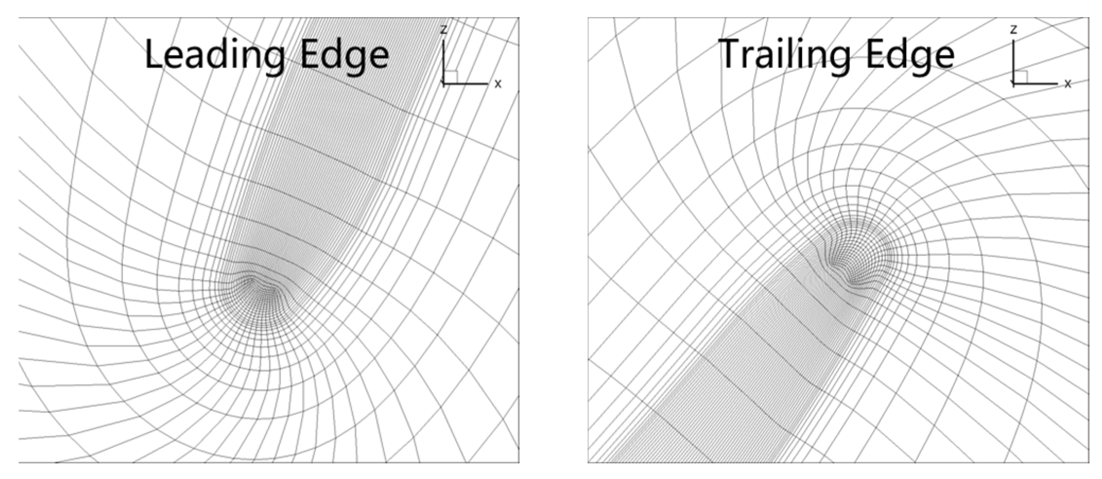
Figure 1 shows a single-passage domain with a bump and buffer zone in the intake generated by the NUMECA Auto Gird, with an O4H topology for blade tip clearance and an HOH topology for blade-to-blade surfaces. Figure 2 displays the closeup view of the mesh near the leading and trailing edges in the tip-gap region. There are 73 layers in the radial direction and 17 layers in the blade tip clearance direction. A variable location bump with a channel height of 6% was set on the shroud surface. At least 40 axial grid points per wavelength of acoustic wave between the bump and the fan were required for a grid convergent solution [11], and the number of grid points near the bump was increased to accurately describe the reflection of acoustic waves. A buffer zone of 6.5 times the chord length was established between the bump and the inlet boundary to prevent numerical reflections. Buffer zones are extensively applied in aeroacoustic [35] and aeroelastic [36] studies due to their simplicity and ease of implementation. To mitigate the detrimental impact of boundary layer growth on the flow in front of the blades, an inviscid slip wall boundary condition was employed for the hub and shroud of the intake.
The computational fluid domain was meshed with structured hexahedral elements. A mesh-independence study was conducted using a computational domain with an extended intake and no bump at 100% speed, and periodic boundary conditions were employed. Three sets of girds were used that feature different degrees of densification with the total number of meshes increasing in steps of 1.5. The one-equation Spalart–Allmaras (S-A) turbulence model was employed for its simple discretization scheme, good computational efficiency, good convergence, and acceptable accuracy. It has been widely used in solving aeroelastic problems [37,38,39]. To meet the requirements of the S-A turbulence model, the height of the first grid elements adjacent to the wall was set to 1 × 10⁻⁵ m; thus, y+ falls within the range of 5 to 8. For boundary conditions, the total pressure (101,325 Pa), total temperature (288.15 K), and the flow angles (0 deg) prescribed at the inflow boundary and the static pressure (102,000 Pa) were imposed at the outflow boundary by a radial equilibrium equation. Nonslip and adiabatic conditions were imposed on all solid walls except the hub and shroud of the intake. In terms of the boundary conditions specified for the turbulence transport variable, the turbulent eddy viscosity, μ T , at the inlet was taken as 0.009 times the laminar kinematic viscosity, denoted μ L . At the outlet boundary, μ T was extrapolated from the interior of the computation domain, and it was set to 0 at solid walls. Computational results in terms of mass flow rate, pressure ratio, and aerodynamic efficiency are summarized in Table 2. In consideration of computational cost and accuracy, the medium grid was chosen for subsequent calculations.
Figure 3 shows the computational domain used for the flutter calculation in this study. The whole annulus mesh was obtained by rotationally copying the single-passage mesh.
The steady aerodynamic characteristics of NASA Rotor 67 at 100% speed calculated using a medium mesh are shown in Figure 4. The working condition was changed by adjusting the outflow boundary pressure, and the calculated results of HGAE and NUMECA are basically consistent and both slightly lower than experimental data.

5. Flow Structures

In this section, the aerodynamic characteristics and flow structures on blade surfaces are investigated. The chosen operating condition corresponds to the peak efficiency point at 100% speed, with an inlet Mach number of approximately 0.54.
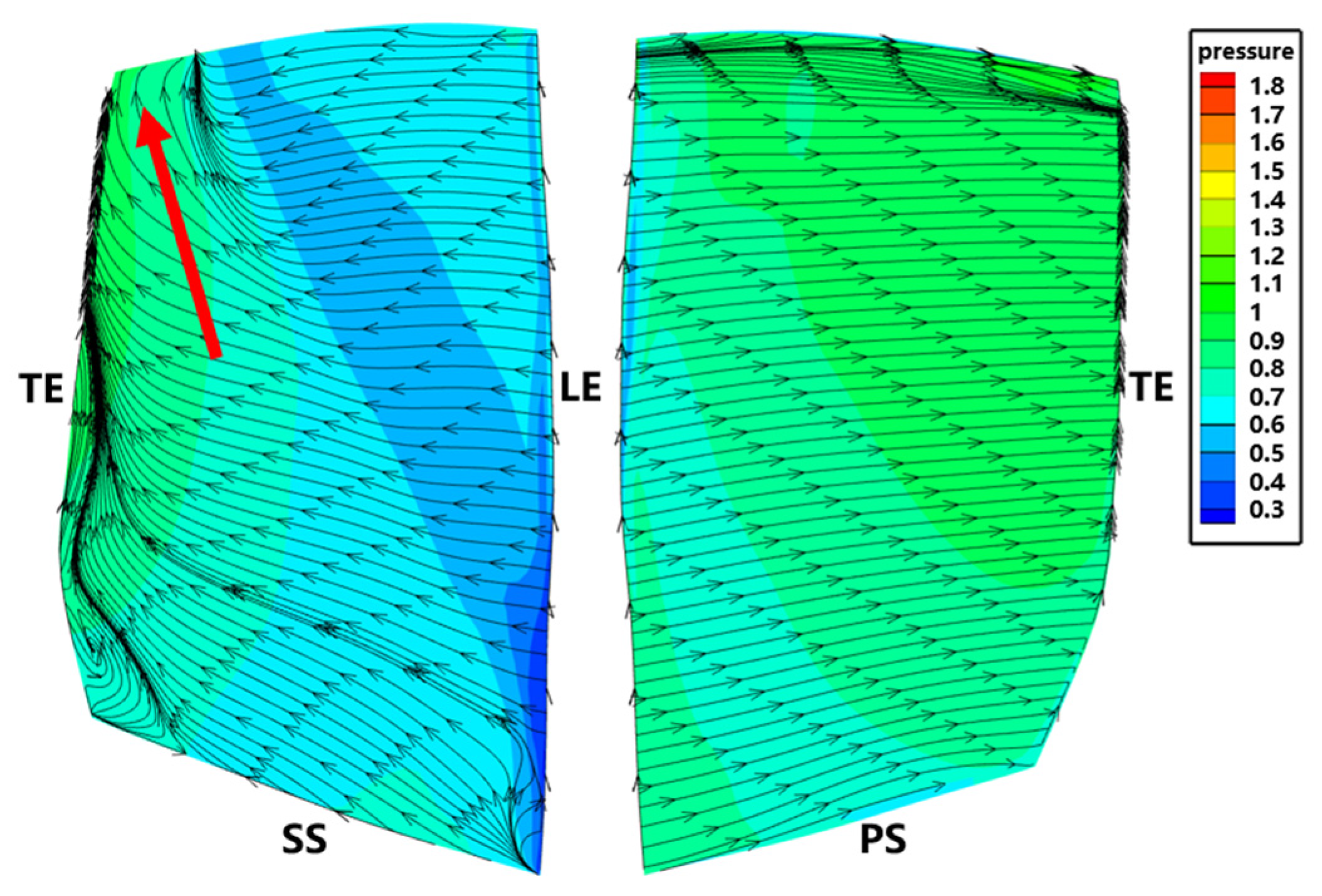
Figure 5 shows the non-dimensional pressure distribution and stream line on the suction surface (SS) and pressure surface (PS) at the peak efficiency. Near the trailing edge on the SS, streamlines converge toward the blade tip, indicating radial flow migration, as indicated by a red arrow. At 70% of the chord length on the SS, the pressure coefficient indicates the presence of adverse transverse pressure gradients behind the shock wave, coinciding with radial flow migration. Convergence of streamlines is observed at both the leading and trailing edges of the PS, which is attributed to the impact of tip leakage flow from the adjacent blade on the PS. Flutter is commonly associated with vigorous unsteady flows, which potentially leads to broadband disturbances, while the flow at the peak efficiency point remains relatively stable, facilitating the extraction of single-frequency acoustic wave characteristics produced by the blade vibration mode.

6. Acoustic Flutter Analysis

6.1. Flow Field Acoustic Properties

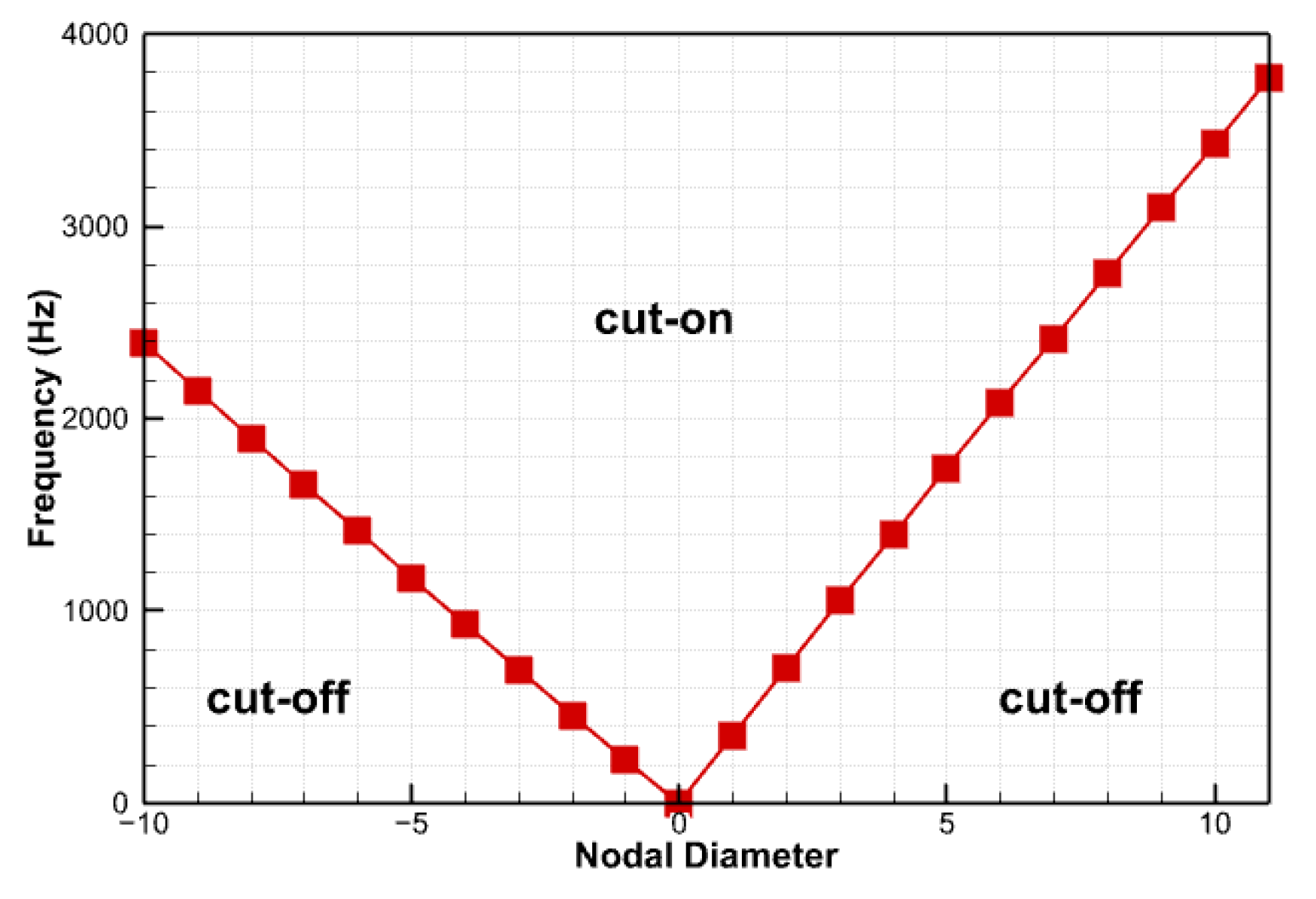
For the NASA Rotor 67 fan, the inlet has no pre-swirl, which indicates M θ = 0. The critical cut-on frequencies at each ND calculated according to Equation (7) based on the fan inlet condition are shown in Figure 6, and the critical frequency at 1ND is 354 Hz. The acoustic wave is cut-on when the blade vibration frequency surpasses the critical frequency and is cut-off when it is below the critical frequency. The blade vibration frequency selected in this study is 360 Hz, which is slightly higher than the critical frequency to ensure that the acoustic wave in the intake is cut-on.
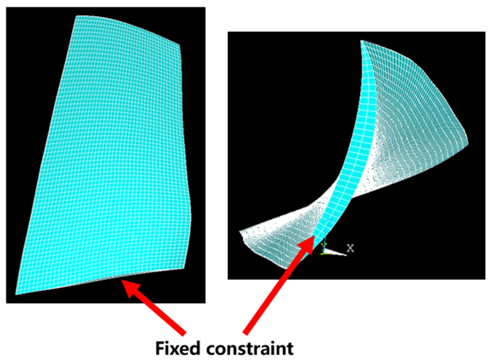
Since the majority of compressor blade vibration issues occur at relatively lower vibration modes, as shown in relevant research [40], understanding the propagation of the most dangerous mode and its effects on blade vibration is critical. Figure 7 displays the FEM model of the fan blade. There are 40 × 65 × 2 hexagonal quadratic elements in the chord-wise, spanwise, and circumferential directions, respectively. The material properties of the blade are shown in Table 3. Following the methodology described earlier, the acoustic characteristics of the intake under the 1ND blade disk mode composed of first bending (1F, as shown in Figure 8) were investigated.
The speed at which pressure waves propagate upstream in the intake is approximately 150 m/s, determined through the propagation of animated pressure waves in the intake (not shown for brevity). Since the incoming Mach number is 0.54 (180 m/s), the propagation speed of the pressure wave in the intake relative to the incoming flow is approximately 330 m/s, which is close to the local speed of sound. Therefore, this pressure wave can be considered an acoustic wave.
The transient unsteady pressure distribution at 99% span in the circumferential direction is illustrated in Figure 9. The potential of the blade rapidly attenuates as it propagates upstream, while the acoustic wave mode corresponding to the 1AWN (from 1ND blade disk mode) can propagate within the intake. The axial wavelength (λ) of the acoustic wave obtained from Figure 9 is approximately 250 mm. Notably, when the bump is too close to the fan, the potential interference, which falls outside the scope of this study, becomes pronounced. Therefore, the bump is initially positioned upstream of the fan at a distance longer than 2 λ to observe the influence of acoustic wave reflections.

6.2. Relationship between the Pressure Waves and Flow Structure

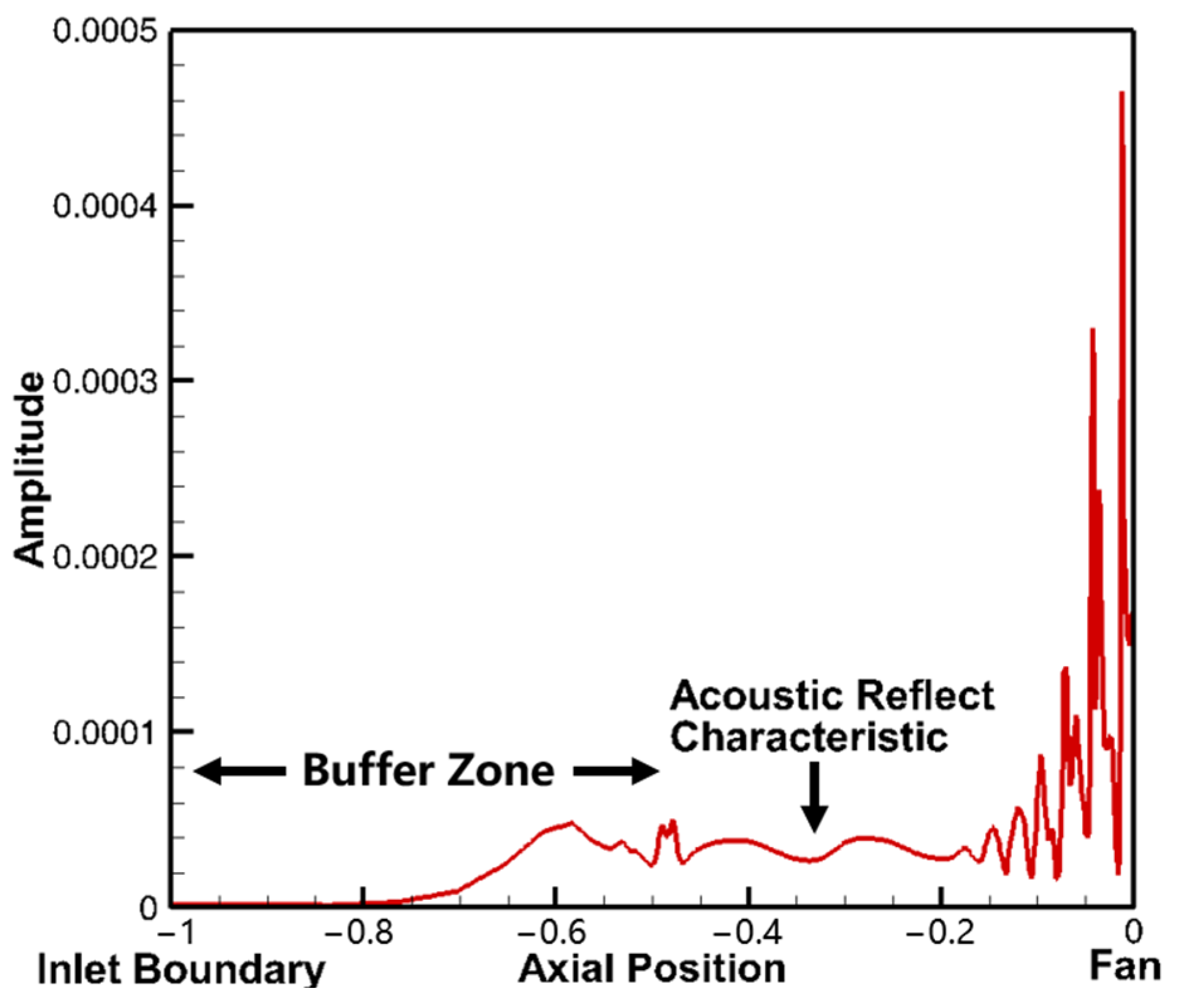
Figure 10 illustrates the axial unsteady pressure amplitude distribution in the intake. The inlet boundary, bump, and fan leading edge are located at −1, −0.5, and 0 in the figure, respectively. The vertical axis represents the unsteady pressure amplitude (Pa) at the blade vibration frequency. The unsteady pressure attenuation is observed from the inlet (−1) to −0.6, which indicates the effectiveness of the buffer zone to mitigate numerical reflections. A clear interference pattern of acoustic waves can be observed from −0.5 to −0.2, which indicates that the bump facilitates the reflection of acoustic waves. The reflected downstream acoustic wave exhibits the same frequency and a fixed phase difference as the upstream acoustic wave generated by the blade vibration, thereby satisfying the conditions for interference.
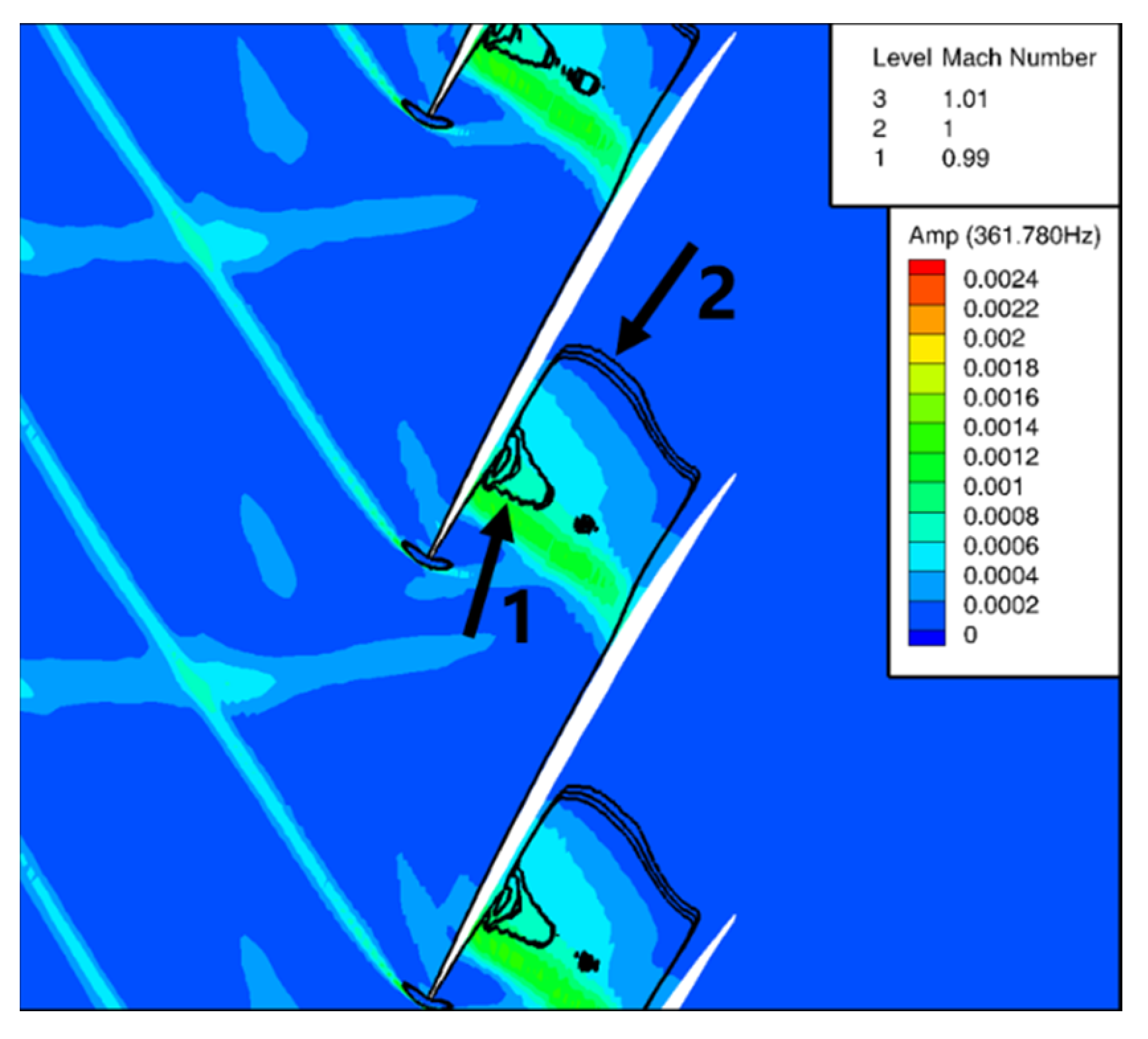
Figure 11 shows the distributions of the unsteady pressure amplitude (obtained through FFT transformation) and Mach number lines at 80% span. Two shock waves, denoted by arrows, are present in the blade passage. Significant unsteady pressures are induced near shock wave 1. Therefore, unsteady pressure amplitudes could provide good indication of variations in the shock wave.

6.3. Acoustic Reflection Analyses

Figure 12 illustrates the variation of the aerodynamic work of the blade with respect to the d bump distance at 2.5 λ, 3 λ, 3.5 λ, and 4 λ upstream of the fan in the intake. The changes in the aerodynamic work (the black line) due to acoustic wave reflection do not always follow a standard sinusoidal pattern. A previous study [11] indicated that when the normalized distance of the bump is an even multiple of the half-wavelength, the blade aeroelastic stability is consistently lower than that in the case with no reflection, while for odd half-wavelengths, the aeroelastic stability is always higher than that in the case with no reflection, as shown in Figure 12.
Based on the findings in Ref. [11], the predicted value of aerodynamic work with the bump position at 2.5 λ and 4 λ should be located in the red regions A and B in the figure. However, the discrepancy between these predicted values and the current results was investigated.
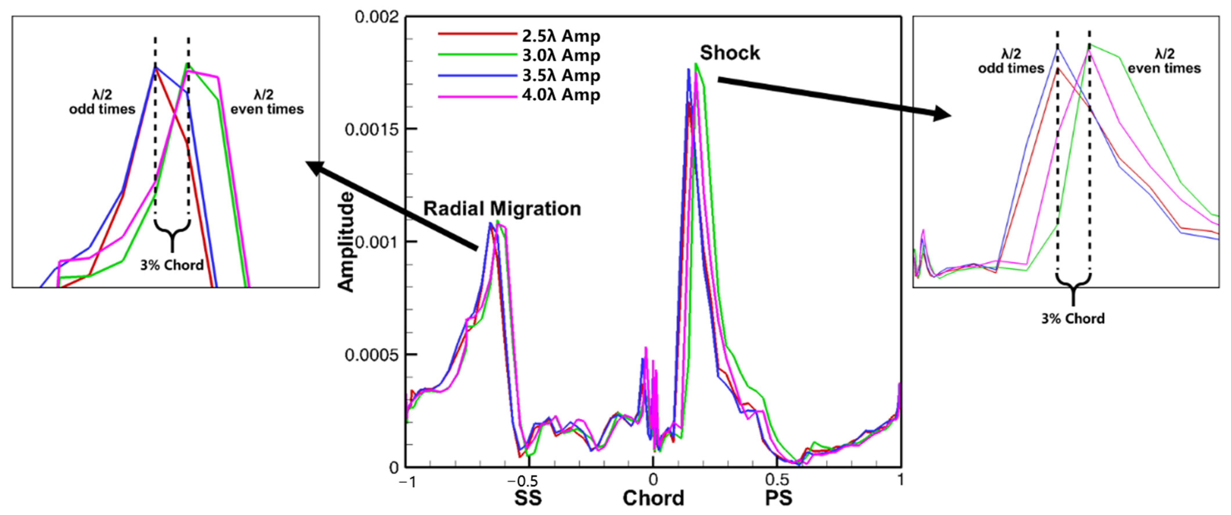
Figure 13 and Figure 14 illustrate the chordwise distribution characteristics of the unsteady pressure phase and amplitude at 80% blade span. The red region in Figure 13 represents aeroelastic instability, while the white region represents aeroelastic stability. The relationship between the unsteady pressure phase and blade stability is expressed in Equation (8). Figure 13 and Figure 14 show that the pressure wave generated by the shock wave exhibits chordwise propagation characteristics on the PS, but does not exhibit the same features on the SS.
W P S = S t a b l e , U n s t a b l e , 180 ° + 2 π n < θ < 0 ° + 2 π n 0 ° + 2 π n < θ < 180 ° + 2 π n , W S S = S t a b l e , U n s t a b l e , 0 ° + 2 π n < θ < 180 ° + 2 π n 180 ° + 2 π n < θ < 0 ° + 2 π n ( n Z )
Because of the strong correlation between the blade surface pressure wave and the shock wave, changes in the shock wave induced by the reflected wave can be inferred by examining the peak values of the unsteady pressure amplitude and phase at the shock wave location, as shown in Figure 13 and Figure 14. The location of the shock wave on the PS and the shock-induced radial flow migration on the SS periodically varies with the phase of the reflected acoustic wave in the chordwise direction, with a variation of approximately 3% in the chord length. This spatial variation can be explained by the acoustic wave interference phenomenon in the intake; the interference between the outgoing and reflected waves in the intake causes an inhomogeneous acoustic pressure in the intake (as the distribution of the acoustic pressure amplitude is in the −0.5~−0.2 region in Figure 10), and the pressure at the fan leading edge p f a n is represented by Equation (9).
p f a n t , λ = p ¯ + p i n t t , λ
p f a n can be decomposed to the time average pressure p ¯ and the acoustic interference pressure p i n t at the fan leading edge. The acoustic pressure at the fan leading edge varies with the phase of the reflected wave, as shown by the uneven distribution of the acoustic pressure amplitude in the axial direction in Figure 10. Figure 15 shows the pressure amplitude of acoustic wave interference occurring in an annular duct. This example is specifically designed to validate the physical phenomenon of acoustic interference in a circular duct. In this case, a rotating 1ND pressure boundary condition is applied at the outlet of the circular duct to simulate the acoustic wave generated by a fan. The pressure waves propagate upstream and numerical reflections occur at the inlet boundary. Interference between the upstream wave and the reflected wave manifests as a result. When two acoustic waves with the same frequency but different propagation directions are present in the annular duct, acoustic wave interference occurs. The characteristic of acoustic wave interference is manifested by an axially uneven distribution of unsteady pressure amplitude. The root of this difference lies in the phase difference between the two acoustic waves, which can be used to determine the pattern. The characteristic of acoustic wave interference in the annular duct is the distribution of the amplitude in a band shape along the propagation direction of the acoustic wave, which corresponds to p i n t in Equation (9). When the phase of the reflected waves changes, slight variations in the actual pressure distribution in front of the fan are caused and subsequently the spatial position of the shock wave is altered.

6.4. Unsteady Pressure Propagation Characteristics on Blade Surfaces

The propagation characteristics of pressure waves on blade surfaces play a key role in blade aeroelastic stability.
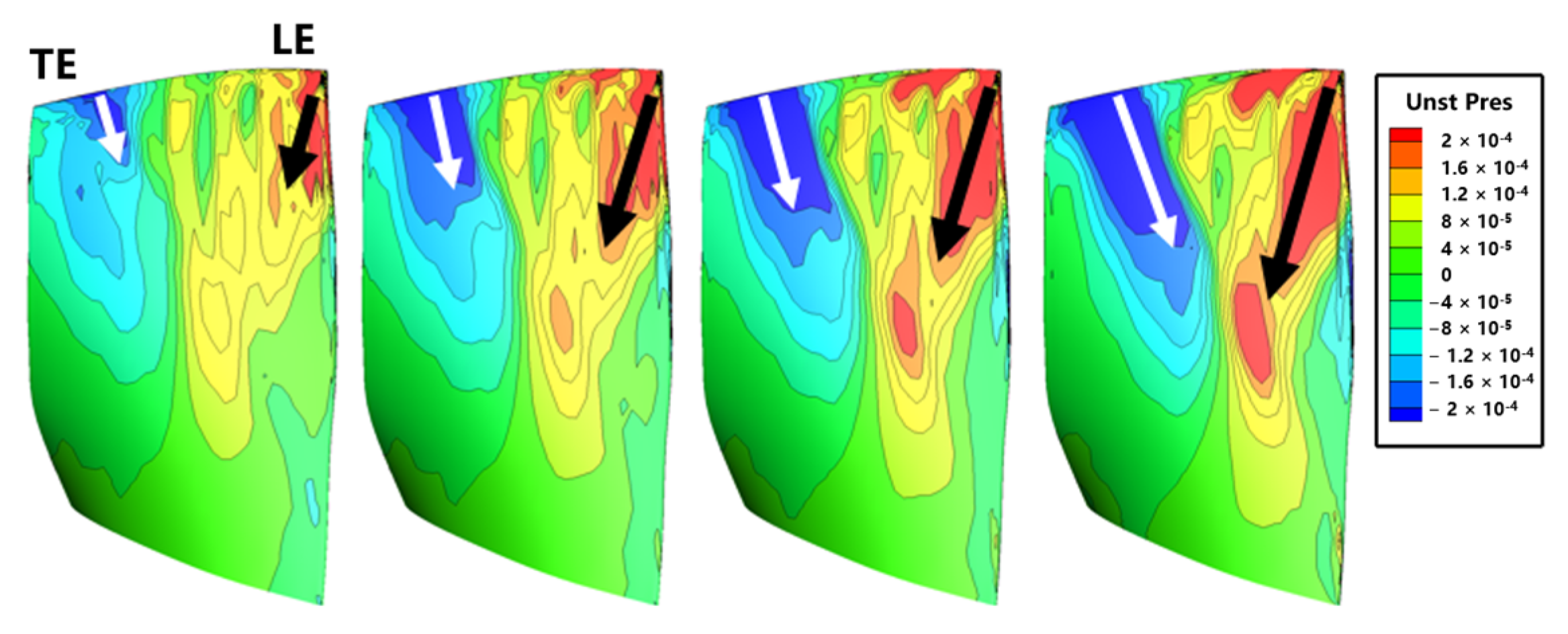
The directions of pressure wave propagation on both surfaces of the blade exhibit significant differences, as shown in Figure 16 and Figure 17. Based on the flow structures, the area where the pressure waves propagate from the mid-chord (the root of the arrow) to the leading edge on the PS, as indicated by the black arrow in Figure 16, is controlled by the shock wave. The mid-chord region near the leading edge on the SS, as indicated by the white arrow in Figure 17, is controlled by radial flow migration, where the pressure waves propagate from the blade tip to the mid-span; the region near the leading edge on the SS, as indicated by the black arrow in Figure 17, is controlled by the tip leakage vortex, where unsteady pressure waves propagate from the blade tip to the mid-span.
To explain the presence of two types of pressure wave propagation characteristic on the SS, the streamline map at the blade tip is plotted in Figure 18. The tip leakage flow at the blade tip mainly originates from the leading edge, while the trailing edge at the tip is primarily dominated by the circumferential flow. Figure 14 shows a close relationship between pressure waves and flow structures; thus, the two types of unsteady pressure propagation characteristic on the SS are closely related to the two flow structures at the blade tip.
Ref. [41] indicated that the presence of vortices in the flow field can influence the properties and propagation of acoustic waves, leading to what is known as an acoustic–vortex coupling phenomenon. In a non-swirl flow, vortex disturbances do not induce pressure changes. However, in a swirl flow, vortex disturbances lead to radial motion and density fluctuations by altering the relative tangential velocity, giving rise to the phenomenon of acoustic–vortex coupling. This results in the presence of two components in the unsteady pressure within the flow field: one predominantly governed by propagating vortices and the other primarily dominated by acoustic pressure, with a weak coupling between the two.
According to this theory, pressure waves at the blade tip are affected by the phenomenon of acoustic–vortex coupling, resulting in a modification of the original unsteady pressure amplitude, either an increase or decrease, and introducing a degree of unpredictability. The propagation characteristics of unsteady pressure on the SS then extend this influence to the mid-span, thus influencing the aeroelastic characteristics of the blades.
Therefore, due to the different pressure wave propagation characteristics on the SS, it is necessary to divide the blade surface into several zones for the blade aeroelastic stability analyses.

6.5. Blade Aeroelastic Stability

Based on the observations regarding the propagation characteristics of pressure waves in the previous sections, the blade surfaces are divided into three zones, as illustrated in Figure 19. These zones are denoted Zone A, dominated by shock wave, where the pressure waves propagate upstream toward the blade leading edge; Zone B, dominated by the radial flow migration, where the pressure waves propagate toward the blade middle span; and Zone C, dominated by the phenomenon of acoustic–vortex coupling, where the pressure waves propagate near the leading edge of the blade. Since the aerodynamic work density is essentially zero from the blade hub to the 50% span, its influence on the aeroelastic stability is minimal. Therefore, the aerodynamic work under 50% span is not considered.
The aerodynamic work density in these three zones is integrated over the area, yielding the results shown in Figure 20. The red line represents the aerodynamic work in each zone, and the gray line represents the standard sine curve. In Zone A, where unsteady pressures are generated by the shock wave, the variations in the shock wave under different reflected acoustic waves directly determine the aeroelastic stability of Zone A. The aerodynamic work exhibits a nearly standard sine pattern with the normalized bump position relative to the fan, indicating that the influence of acoustic interference on the shock wave is sinusoidal. In Zones B and C, unsteady pressures are generated at the blade tip, with the propagation directions from the blade tip to the mid-span. This transmission of pressure waves, influenced by the radial flow migration in Zone B, and the acoustic–vortex coupling phenomenon at the tip to the mid-span in Zone C, results in slight deviations from the perfect sine pattern in the variations of aerodynamic work. This explains why the aerodynamic work on the suction surface always slightly deviates from the sinusoidal pattern.
Overall, the above analyses explain the reasons for the deviation from the sinusoidal curve in the overall aerodynamic work variation, as shown in Figure 12, although the variations in blade aeroelastic stability induced by changes in the spatial position of shock waves are sinusoidal. The operating conditions selected in Ref. [11] predominantly involve an attached flow on blade surfaces with no radial flow migration. Consequently, the aeroelastic stability exhibits a sinusoidal characteristic with the phase of the different reflected acoustic waves.

7. Conclusions

The in-house numerical code HGAE was used to study the flutter characteristics of the fan rotor caused by the acoustic wave reflection in the intake via an energy method. The influence of flow structures on the impact of acoustic wave reflections on the blade aeroelastic stability was investigated in detail, which had not been done before. It was clarified that the reason for the change in aeroelastic stability caused by acoustic reflection is its effects in different flow regions. The main conclusions can be summarized as follows:
  • The position of the shockwave is determined by the phase of the reflected acoustic waves, and the change in the shock wave position is the primary cause of the change in the blade aeroelastic stability under the influence of acoustic wave reflections. When wave reflection occurs upstream of the fan, the outgoing acoustic waves interfere with the reflected waves, resulting in a band-shaped axial distribution of the acoustic pressure. Different phases of the reflected waves represent varying magnitudes of the interfered acoustic pressure in front of the fan, consequently causing chordwise position variations in the shock wave and altering the blade aeroelastic stability.
  • The effect of reflected waves on the local aeroelastic stability of blade surfaces varies in different zones dominated by different flow structures influencing the propagation of pressure waves. The amplitude variation of the pressure waves varies in the areas affected by the tip leakage flow and radial flow migration. This explains why the aerodynamic work on the suction surface always slightly deviates from the sinusoidal pattern.
  • In prior studies, there has been a lack of attention directed toward investigating the influence of intake acoustic reflections on flow structures in the vicinity of blades. This study revealed that the influence of acoustic wave reflection on blade aeroelasticity cannot be dissociated from that of flow structures. Due to the interference of acoustic waves in the intake, the pressure in front of the fan changes, eventually leading to a shift in the position of the shock wave.
  • The above findings imply that acoustic wave reflection plays an important role in the aeroelastic stability of the blade by affecting the flow structures. Thus, the intake geometry should be carefully selected. In our study, acoustic–vortex coupling is observed, but its effects on the blade aeroelastic stability are not discussed. Further study on this topic should help to clarify the physical mechanism of acoustic flutter.

Author Contributions

Conceptualization, H.L. and H.Y.; methodology, H.Y. and H.L.; software, Y.Z.; validation, H.L. and H.Y.; formal analysis, H.L.; investigation, H.Y. and H.L.; resources, Y.Z.; data curation, H.L.; writing—original draft preparation, H.L.; writing—review and editing, H.Y. and H.L.; visualization, H.L.; supervision, H.Y.; project administration, Y.Z.; funding acquisition, Y.Z. All authors have read and agreed to the published version of the manuscript.

Funding

This research was funded by National Science and Technology Major Project (2017-II-0009-0023).

Data Availability Statement

The original contributions presented in the study are included in the article, further inquiries can be directed to the corresponding authors.

Conflicts of Interest

The authors declare no conflict of interest.

References

  1. Srinivasan, A.V. Flutter and Resonant Vibration Characteristics of Engine Blades. J. Eng. Gas Turbines Power 1997, 119, 742–775. [Google Scholar] [CrossRef]
  2. Isomura, K.; Giles, M.B. A Numerical Study of Flutter in a Transonic Fan. J. Turbomach. 1998, 120, 500–507. [Google Scholar] [CrossRef]
  3. Lane, F. System Mode Shapes in the Flutter of Compressor Blade Rows. J. Aeronaut. Sci. 1956, 23, 54–66. [Google Scholar] [CrossRef]
  4. Hansen, M.H. Aeroelastic instability problems for wind turbines. Wind Energy 2007, 10, 551–577. [Google Scholar] [CrossRef]
  5. Vogt, D.M.; Fransson, T.H. Experimental Investigation of Mode Shape Sensitivity of an Oscillating Low-Pressure Turbine Cascade at Design and Off-Design Conditions. J. Eng. Gas Turbines Power 2006, 129, 530–541. [Google Scholar] [CrossRef]
  6. Copeland, G.; Rey, G. Comparison of experiments and reduced-order models for turbomachinery high-incidence flutter. J. Fluids Struct. 2004, 19, 713–727. [Google Scholar] [CrossRef]
  7. Waite, J.J.; Kielb, R.E. Physical Understanding and Sensitivities of Low Pressure Turbine Flutter. J. Eng. Gas Turbines Power 2014, 137, 012502. [Google Scholar] [CrossRef]
  8. Srivastava, R.; Keith, T.G. Influence of Shock Wave on Turbomachinery Blade Row Flutter. J. Propuls. Power 2005, 21, 167–174. [Google Scholar] [CrossRef]
  9. Sanders, A.J.; Hassan, K.K.; Rabe, D.C. Experimental and Numerical Study of Stall Flutter in a Transonic Low-Aspect Ratio Fan Blisk. J. Turbomach. 2004, 126, 166–174. [Google Scholar] [CrossRef]
  10. Aotsuka, M.; Murooka, T. Numerical Analysis of Fan Transonic Stall Flutter. In Proceedings of the ASME Turbo Expo 2014: Turbine Technical Conference and Exposition. Volume 7B: Structures and Dynamics, Düsseldorf, Germany, 16–20 June 2014. [Google Scholar] [CrossRef]
  11. Vahdati, M.; Simpson, G.; Imregun, M. Mechanisms for Wide-Chord Fan Blade Flutter. J. Turbomach. 2011, 133, 041029. [Google Scholar] [CrossRef]
  12. Iseni, S.; Micallef, D.; di Mare, F. Sensitivity analysis of eigenmode variations on the flutter stability of a highly loaded transonic fan. In Proceedings of the GPPS Forum 18 Global Power and Propulsion Society, Montreal, QC, Canada, 7–9 May 2018. [Google Scholar]
  13. Purushothaman, K.; Naveen Kumar, N.R.; Jeyaraman, S.K.; Pratap, A. Aeroelastic instability evaluation of transonic compressor at design and off-design conditions. In Proceedings of the National Aerospace Propulsion Conference; Springer: Singapore, 2020; pp. 39–61. [Google Scholar]
  14. Dong, X.; Zhang, Y.; Zhang, Y.; Zhang, Z.; Lu, X. Numerical simulations of flutter mechanism for high-speed wide-chord transonic fan. Aerosp. Sci. Technol. 2020, 105, 106009. [Google Scholar] [CrossRef]
  15. Möller, D.; Jüngst, M.; Holzinger, F.; Brandstetter, C.; Schiffer, H.-P.; Leichtfuß, S. Mechanism of Nonsynchronous Blade Vibration in a Transonic Compressor Rig. J. Turbomach. 2016, 139, 011002. [Google Scholar] [CrossRef]
  16. Dong, X.; Zhang, Y.; Zhang, Z.; Lu, X.; Zhang, Y. Effect of Tip Clearance on the Aeroelastic Stability of a Wide-Chord Fan Rotor. J. Eng. Gas Turbines Power 2020, 142, 091010. [Google Scholar] [CrossRef]
  17. Vahdati, M.; Sayma, A.I.; Breard, C.; Imregun, M. Computational Study of Intake Duct Effects on Fan Flutter Stability. AIAA J. 2002, 40, 408–418. [Google Scholar] [CrossRef]
  18. Lee, K.-B.; Wilson, M.; Vahdati, M. Numerical Study on Aeroelastic Instability for a Low-Speed Fan. J. Turbomach. 2017, 139, 071004. [Google Scholar] [CrossRef]
  19. Vahdati, M.; Smith, N.; Zhao, F. Influence of Intake on Fan Blade Flutter. J. Turbomach. 2015, 137, 081002. [Google Scholar] [CrossRef]
  20. Gallardo, J.M.; Sotillo, A.; Bermejo, Ó. Study of the Effect of the Scatter of Acoustic Modes on Turbine Flutter. J. Turbomach. 2019, 141, 101010. [Google Scholar] [CrossRef]
  21. Dong, X.; Zhang, Y.; Lu, X.; Zhang, Y.; Gan, J. Numerical Investigation of the Fan Flutter Mechanism Related to Acoustic Propagation Characteristics. J. Turbomach. 2022, 144, 101009. [Google Scholar] [CrossRef]
  22. Oh, J.Y.; Ma, F.; Hsieh, S.-Y.; Yang, V. Interactions Between Shock and Acoustic Waves in a Supersonic Inlet Diffuser. J. Propuls. Power 2005, 21, 486–495. [Google Scholar] [CrossRef]
  23. Feldhusen, A.; Hartmann, A.; Klaas, M.; Schröeder, W. Impact of alternating trailing-edge noise on buffet flows. In Proceedings of the 31st AIAA Applied Aerodynamics Conference, San Diego, CA, USA, 24–27 June 2013. [Google Scholar] [CrossRef]
  24. Blazek, J. Computational Fluid Dynamics: Principles and Applications; Elsevier BV: Amsterdam, The Netherlands, 2015; ISBN 9780080999951. [Google Scholar] [CrossRef]
  25. Zheng, Y.; Yang, H. Coupled Fluid-structure Flutter Analysis of a Transonic Fan. Chin. J. Aeronaut. 2011, 24, 258–264. [Google Scholar] [CrossRef]
  26. Roe, P. Approximate Riemann solvers, parameter vectors, and difference schemes. J. Comput. Phys. 1981, 43, 357–372. [Google Scholar] [CrossRef]
  27. van Leer, B. Towards the Ultimate Conservative Difference Scheme. J. Comput. Phys. 1997, 135, 229–248. [Google Scholar] [CrossRef]
  28. Jameson, A. Time dependent calculations using multigrid, with applications to unsteady flows past airfoils and wings. In Proceedings of the 10th Computational Fluid Dynamics Conference, Honolulu, HI, USA, 24–26 June 1991. [Google Scholar] [CrossRef]
  29. Zheng, Y.; Jin, X.; Yang, H. Low-Engine-Order Forced Response Analysis of a Turbine Stage with Damaged Stator Vane. Entropy 2023, 26, 4. [Google Scholar] [CrossRef]
  30. Zheng, Y.; Gao, Q.; Yang, H. Forced Response Analysis of an Embedded Compressor Rotor Induced by Stator Disturbances and Rotor–Stator Interactions. Aerospace 2023, 10, 398. [Google Scholar] [CrossRef]
  31. Zheng, Y.; Jin, X.; Yang, H. Effects of Asymmetric Vane Pitch on Reducing Low-Engine-Order Forced Response of a Turbine Stage. Aerospace 2022, 9, 694. [Google Scholar] [CrossRef]
  32. Carta, F.O. Coupled Blade-Disk-Shroud Flutter Instabilities in Turbojet Engine Rotors. J. Eng. Power 1967, 89, 419–426. [Google Scholar] [CrossRef]
  33. Tyler, J.M.; Sofrin, T.G. Axial Flow Compressor Noise Studies. SAE Tech. Pap. 1962, 70, 309–332. [Google Scholar] [CrossRef]
  34. Hellmich, B.; Seume, J.R. Causes of Acoustic Resonance in a High-Speed Axial Compressor. J. Turbomach. 2008, 130, 031003. [Google Scholar] [CrossRef]
  35. Broatch, A.; García-Tíscar, J.; Roig, F.; Sharma, S. Dynamic mode decomposition of the acoustic field in radial compressors. Aerosp. Sci. Technol. 2019, 90, 388–400. [Google Scholar] [CrossRef]
  36. Buchwald, P.; Farahmand, A.; Vogt, D.M. On the Influence of Blade Aspect Ratio on Aerodynamic Damping. J. Turbomach. 2019, 141, 101007. [Google Scholar] [CrossRef]
  37. Spalart, P.R.; Allmaras, S.R. A one-equation turbulence model for aerodynamic flows. In Proceedings of the 30th Aerospace Sciences Meeting and Exhibit, Reno, NV, USA, 6–9 January 1992. [Google Scholar]
  38. Espinal, D.; Im, H.-S.; Zha, G.-C. Full-Annulus Simulation of Nonsynchronous Blade Vibration Excitation of an Axial Compressor. J. Turbomach. 2017, 140. [Google Scholar] [CrossRef]
  39. Stapelfeldt, S.; Brandstetter, C. Non-synchronous vibration in axial compressors: Lock-in mechanism and semi-analytical model. J. Sound Vib. 2020, 488, 115649. [Google Scholar] [CrossRef]
  40. Zhang, X.-Y.; Zhang, X.-Y.; Guo, S.-R. Efficient copper(I)-catalyzed C–S cross-coupling of thiols with aryl halides in an aqueous two-phase system. J. Sulfur Chem. 2011, 32, 23–35. [Google Scholar] [CrossRef]
  41. Kerrebrock, J.L. Small disturbances in turbomachine annuli with swirl. AIAA J. 1977, 15, 794–803. [Google Scholar] [CrossRef]
Figure 1. Single-passage mesh with bump and buffer zone.
Aerospace 11 00358 g001
Figure 2. Mesh in the tip-gap region.
Aerospace 11 00358 g002
Figure 3. Computational domain.
Aerospace 11 00358 g003
Figure 4. Efficiency and pressure ratio of the NASA Rotor 67 at 100% speed.
Aerospace 11 00358 g004
Figure 5. Blade surface pressure coefficient superimposed limit streamlines.
Aerospace 11 00358 g005
Figure 6. Critical cut-on frequencies at each ND.
Aerospace 11 00358 g006
Figure 7. Structural mesh of the fan blade.
Aerospace 11 00358 g007
Figure 8. 1F vibration mode at 100% speed (360 Hz).
Aerospace 11 00358 g008
Figure 9. Transient unsteady pressure distribution at 99% span.
Aerospace 11 00358 g009
Figure 10. Axial unsteady pressure amplitude distribution in the intake.
Aerospace 11 00358 g010
Figure 11. Unsteady pressure amplitude contour and Mach number lines at 80% span.
Aerospace 11 00358 g011
Figure 12. Aerodynamic work as a function of the bump position.
Aerospace 11 00358 g012
Figure 13. Phase distribution of unsteady pressure at 80% span.
Aerospace 11 00358 g013
Figure 14. Unsteady pressure amplitude distribution at 80% span.
Aerospace 11 00358 g014
Figure 15. Example of acoustic interference in an annular duct.
Aerospace 11 00358 g015
Figure 16. Unsteady pressure on the PS at five instants.
Aerospace 11 00358 g016
Figure 17. Unsteady pressure on the SS at four instants.
Aerospace 11 00358 g017
Figure 18. Flow streamlines at the tip.
Aerospace 11 00358 g018
Figure 19. Aerodynamic work density distribution and dominated zones of flow structures.
Aerospace 11 00358 g019
Figure 20. Aerodynamic work with bump position in different zones.
Aerospace 11 00358 g020
Table 1. Geometry parameters of NASA Rotor 67.
ParameterUnitValue
Number of Blades-22
Tip Clearancemm1.016
Design Rotational Speedrpm16,043
Inlet Tip Diametercm51.4
Outlet Tip Diametercm48.5
Hub/Tip Radius Ratio at Leading Edge-0.375
Hub/Tip Radius Ratio at Trailing Edge-0.478
Table 2. Mesh-independence analysis.
Mesh LevelTotal Mesh PointMass Flow RatePressure RatioEfficiency
Coarse752,76334.10371.5880.8976
Medium1,207,32534.05881.5920.8996
Fine1,565,43434.02061.5910.8991
Table 3. Material properties of the blade.
Elasticity Modulus (GPa)Poisson RatioDensity (kg/m3)
1100.334400
Disclaimer/Publisher’s Note: The statements, opinions and data contained in all publications are solely those of the individual author(s) and contributor(s) and not of MDPI and/or the editor(s). MDPI and/or the editor(s) disclaim responsibility for any injury to people or property resulting from any ideas, methods, instructions or products referred to in the content.