Abstract
As an advanced design technology for large wide-body airliners, the three-dimensional (3D) dual-sidestay (DSS) landing gear retraction mechanism can share the ground loads transferred by the landing gear, reducing the load on the wings. However, the addition of a strut system may significantly impact the synchronous locking performance of the landing gear with extremely high sensitivity. To study this impact pattern, both a rigid–flexible-coupling dynamic model of DSS landing gear considering joint clearance and node deviation and a synchronous locking test platform are established in this paper, and the simulation model is validated through the experimental results. Based on the simulation model, this paper conducts a detailed study on the influence of different node deviations and joint clearance on the synchronous locking dynamic characteristics of the DSS landing gear. The results show that, as the node deviation increases, the locking of the lock link gradually lags until one side cannot be fully locked; the structural clearance has a smaller impact on the synchronous locking of the landing gear. The feasible region of parameters satisfying the synchronous locking condition is given, which provides a basis and support for the parameter design of dual-sidestay retraction mechanisms.
1. Introduction
The landing gear retraction system is closely related to the take-off and landing safety and flight performance of the aircraft [1,2]. Most modern aircraft use retraction mechanisms to reduce aerodynamic drag during flight [3]. Moreover, the retractable mechanism can transmit the load of the aircraft during take-off, landing, and taxiing when it is downlocked [4]. While the supercritical airfoil improves the aerodynamic performance of the aircraft, it reduces the storage space of the landing gear retraction mechanism [5], and the extensive use of composite materials in the structural components of wide-body aircraft will reduce its load-bearing capacity [6]. To meet the storage space and load transfer requirements of large wide-body airliners, the retraction mechanism has become increasingly complex. It has evolved from having a single-sidestay system to having double-sidestay systems [7,8], transitioning from a 2D planar retraction form to a 3D spatial retraction form [9]. Additional sidestay links are generally installed at the reinforced frame of the aircraft fuselage; these links can effectively share the load borne by the wings and optimize the load transfer of the main landing gear [10]. Moreover, this approach can significantly reduce the vertical space, solving the problem that the planar retraction mechanism has difficulty in retracting the landing gear along a complex trajectory into a narrow space [11]. Moreover, this complex retraction leads to some new problems. The addition of multiple sidestay systems transforms the landing gear from a simple statically determinate structure to a complex hyperstatic structure with high motion sensitivity. For the dual-sidestay retraction mechanism, the coordinated movement of the links on both sides becomes particularly important. If the structural parameters are not reasonably designed, the fore and aft struts will interfere with each other, resulting in the landing gear being unable to downlock synchronously. The unlocked landing gear mechanism cannot effectively withstand the landing load, which can cause the landing gear to collapse. Therefore, it is necessary to carry out the simulation and test of the dynamic characteristics of the DSS landing gear and analyze the influence of key parameters on the locking coordination performance. This makes it easier for designers to comprehend how parameters relate to the DSS performance and parameter boundaries.
The design of the retraction mechanism is increasingly becoming the core content of the landing gear system design. With the rapid development of digital prototype technology, the design means of landing gear mechanisms have also changed from traditional theoretical calculations and empirical design to multidisciplinary collaborative simulation optimization design. This approach enables the consideration of more complex factors at the design stage and intuitively verifies the accuracy of the design and the interference of the mechanism movement, thereby greatly reducing the cost and cycle of landing gear design and improving the efficiency of development and resource utilization. Fan et al. [12] established a digital prototype of the complex spatial retraction mechanism of landing gear based on CATIA, optimized the motion trajectory of the retraction space, and conducted interference checks. Tian et al. [13] established dynamic simulation models of a landing gear retraction mechanism and hydraulic system based on LMS Virtual.Lab Motion and AMESim, respectively, and obtained the dynamic characteristics during the retraction process of the landing gear. Cui et al. [14] conducted an analysis of the kinematic and dynamic characteristics of the landing gear. Huang et al. [15] established a retraction dynamic model and studied the impact of different key parameters on the efficiency of landing gear retraction. Krakowska [16] established the dynamic model of the nose landing gear mechanism and discussed the influence of friction on the retraction system. However, the above scholars have not carried out relevant tests to verify the results. The landing gear retraction test belongs to the landing gear system test, which plays an important role in the safety and reliability of the aircraft. Through the retraction test, the possible defects and problems in the mechanism and system can be found in time, which provides a realistic basis for later improvement and optimization and reduces unnecessary losses. The existing practical engineering research on the retraction mechanism rarely involves the 3D DSS mechanism, and there is almost no synchronous locking test. Therefore, based on the dynamic analysis model, the test scheme of synchronous locking of dual-sidestay landing gear was designed. In order to verify the accuracy of the simulation analysis results, the landing gear synchronous locking performance test considering the influence of the node deviation and joint clearance was designed, and the results were analyzed in detail.
For the 3D DSS retraction mechanism, the motion coordination of the two sidestay systems in the process of downlocking puts forward higher requirements for the design of the landing gear mechanism, and many scholars have conducted research in this field. Regarding the synchronous locking stability issue of the sidestay landing gear, Xin et al. [17] took the locking spring as the design object, discussed the locking principle and structural characteristics of the lock mechanism, and calculated the design load of the locking spring. Knowles et al. [18] proposed a new method based on bifurcation theory to study and analyze the locking performance of the landing gear lock link mechanism and reported that the lock links jump to accomplish the locking moment. Yin et al. [19] studied the single-sidestay (SSS) main landing gear, analyzed the impact of the unlocking force on the retraction process of the landing gear, and optimized the critical unlocking force. Sinchai et al. [20] optimized the unlock spring stiffness by conducting a kinematics bifurcation analysis and tremendously reduced the actuator force. In the research of DSS landing gear, Knowles et al. [21] addressed the issue of the unlocking and locking of 3D retraction landing gear being very sensitive to related parameters. Based on the mechanical equilibrium equation, the flexibility deformation of the linkage was reduced. Furthermore, the complete locking performance of the landing gear is strongly influenced by the position of the sidestays. Xu et al. [11] conducted a bifurcation analysis on the configuration, cooperative locking, and parameter impact of the 3D DSS retraction mechanism, solving the kinematic problem of the two sidestay links interfering with each other during locking process. However, the current research is generally based on the full rigidity mechanical model of ideal articulation. The difference between the existing theoretical analysis and actual situation mainly lies in the node deviation caused by the structural clearance and the body deformation, which can weaken the sensitivity of synchronous downlocking of the landing gear to a certain extent [22], leading to a more conservative research conclusion. For a motion mechanism, the two components with joint connection are often in the form of clearance fit to meet the requirements of flexible operation of the mechanism [23]. If the clearance is too small, there will be a large friction between the structures, which makes the movement of the mechanism not smooth, and the structural wear will be more serious. On the contrary, if the clearance is too large, for the linkage mechanism with high precision positioning requirements, the existence of the clearance will greatly reduce the accuracy of the mechanism motion. Therefore, it is of great significance to establish a reasonable and effective dynamic model with joint clearance, analyze the influence of clearance on the motion performance of the mechanism, and design a reasonable clearance range for different functional mechanisms [24]. Therefore, a rigid–flexible-coupling dynamic model was constructed using the clearance modeling method, which is based on the continuous contact force model and modified Coulomb friction model [25]. And the relevant test was designed to verify the accuracy of the model. It is anticipated that this method of modeling can be expanded to analyze other link mechanisms.
This paper conducts a dynamic simulation analysis of the DSS landing gear retraction mechanism supplemented by relevant test research. This paper is organized as follows. In Section 2, the configuration and operating principle of the DSS landing gear are elaborated. In Section 3, a rigid–flexible-coupling dynamic model of DSS landing gear considering joint clearance and node deviation is established in LMS Virtual.Lab Motion. Furthermore, the design of the test of the synchronous locking of DSS landing gear is discussed, and the accuracy of the simulation analysis model is verified through the test results. In Section 4, the synchronous locking ability of DSS landing gear with node deviation in different directions and different joint clearance sizes is studied, respectively, combined with the verification of relevant test results, and the feasible region of structural parameters which can satisfy the synchronous locking of DSS landing gear is given. Finally, conclusions derived from the above research and analysis are presented in Section 5.
2. Composition and Principle of DSS Landing Gear
This paper primarily investigates the 3D retraction mechanism of the DSS main landing gear typical of wide-body aircraft, as illustrated in Figure 1. The entire landing gear can be divided into three relatively independent link systems: the main strut system, the fore sidestay system, and the aft sidestay system. The main strut system consists of the main strut and wheels, while the fore and aft sidestay systems are composed of sidestay links, lock links, sidestay nodes, lock nodes, locking springs, and unlocking actuators, among other components. Due to the inconsistency between the rotation plane of the main strut and the rotation planes of two sidestay links, analyzing the mechanism in the same coordinate system is challenging. Therefore, the mechanism can be divided into the above three link systems according to the plane of the retraction motion, and geometric constraint relationships can be established separately. The fore and aft sidestay links are the main load-bearing components, and the fore and aft lock links undertake the function of landing gear downlocking. The ground load received by the aircraft is transmitted mainly to the wing through the fore sidestay link and to the fuselage through the aft sidestay link, meaning that the links on both sides generally cannot be designed in a completely symmetrical form.
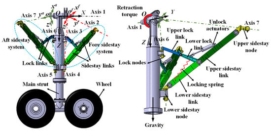
Figure 1.
Schematic of a certain dual-sidestay landing gear.
A Cartesian global coordinate system, O-XYZ; a local link system, , for the fore sidestay system; and a local link system, , for the aft sidestay system were established on the landing gear, as shown in the figure. The origin, O, represents the intersection of the landing gear’s connection axis with the fuselage and the axis of the main strut. The flight direction serves as the X-axis (axis 1) direction of the global coordinate system, the downward direction of the main strut axis serves as the Z-axis direction of the global coordinate system, and the Y-axis is determined by the right-hand rule.
For landing gear with a two-dimensional plane retraction form, its main strut and sidestay links move in the same plane. However, the fore and aft sidestay systems of the 3D DSS retraction mechanism not only perform a folding motion but also rotate around specific axes (axis 2 for the fore sidestay system and axis 7 for the aft sidestay system) [11]; thus, the main strut and the two sidestay systems are not in the same plane. To complete the retraction process, the 3D retraction of the main landing gear must follow the principle of “four axes intersecting at one point”. That is, for the fore sidestay system, the rotation axis of the main strut (axis 1), the axis of fore lock node (axis 3), the axis of the upper node of the fore sidestay link (axis 2), and the axis of the lower node of the fore sidestay link (axis 4) must intersect at one point, . Furthermore, for the aft sidestay system, the relevant axes must intersect at one point, . In this way, the two sidestay systems can move within their respective planes.
The retraction process of the landing gear is as follows: When the landing gear is retracted, under the action of the unlocking actuator, the upper and lower lock links on both sides fold up to a certain angle to complete the unlocking action. Then, under the load of the retraction actuator, the main strut rotates upward around the rotation joint axis (axis 1) at the root to retract until the lock column hangs at the upper hook ring lock to complete the uplocking, and the fore and aft sidestay systems follow the movement to the retracted position. When the landing gear is extended, the main strut is gradually lowered around the axis due to the combined effects of gravity and the retraction actuator. When it is close to the locking position, the lock link quickly jumps from the upper over-center state ( > 0° in Figure 2a) to the lower over-center state ( < 0° in Figure 2b) under the action of the locking spring and stabilizes at the position of the limit block, finally completing the landing gear’s downlocking.
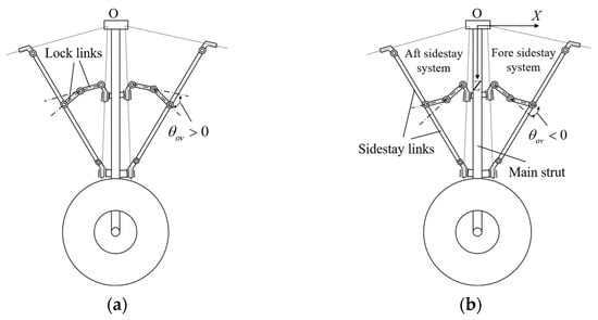
Figure 2.
Locking process of DSS landing gear: (a) description of the upper over-center unlocked state and (b) description of the lower over-center locked state.
3. Dynamic Simulation and Experimental Verification of the Landing Gear Extension Process
3.1. Dynamic Simulation Model of the Landing Gear Retraction Mechanism
This paper establishes a rigid–flexible-coupling dynamic simulation analysis model of the DSS landing gear based on LMS Virtual.Lab Motion 12 software. The main steps are as follows:
3.1.1. Multi-Rigid-Body Dynamic Simulation Model
On the premise of satisfying the mass and moment of inertia of the landing gear, the components of the landing gear are appropriately simplified, the motion pair is established according to the component motion relationship shown in Figure 3, the installation deviation of the node is simulated by applying displacement drive at the node, and loads such as the locking spring force and retraction actuator damping force are added.
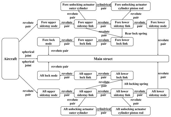
Figure 3.
Schematic of motion relationship of different components.
3.1.2. Landing Gear Joint Clearance Model
- Hole–shaft Clearance Model
For the DSS landing gear retraction system, the influence of the hole–shaft clearance cannot be ignored. A reasonable hole–shaft clearance modeling method can ensure the accuracy of the dynamic analysis. Usually, the kinematic pair models with clearance include the geometric motion model of the revolute pair, the geometric motion model of the cylindrical pair, and the geometric motion model of the spherical joint. According to the actual motion situation, the kinematic pairs in the modeling process of the landing gear retraction mechanism in this paper mostly adopt the cylindrical pair form of the shaft pin and the sleeve. Due to the existence of clearance, the position and contact mode of shaft pins in the sleeve will change with the forces and moments they receive. The contact mode of the landing gear cylindrical pair is roughly divided into the following four forms:
It is worth noting that the complete separation mode of the hole and the shaft in Figure 4a and the one-point contact mode in Figure 4b are both instantaneous unstable modes, while the two-point contact mode and the line contact mode are stable modes.
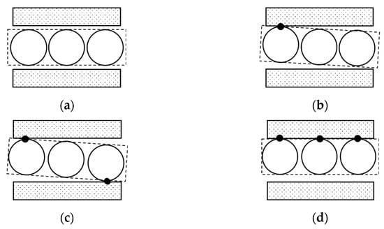
Figure 4.
Cylindrical pair model with clearance: (a) complete separation mode, (b) one-point contact mode, (c) two-point contact mode, and (d) line contact mode.
- 2.
- Contact Force Model
The continuous contact force model considers that there are contact and separation modes in the clearance model. The contact surface of the component is flexible, and the normal contact force and the tangential friction force are applied on the contact surface at the same time.
- Normal contact force:
In order to establish a fine contact force model, the influence of the damping force must not be completely ignored. With the development of the contact force model, more and more collision contact force models considering the damping force are proposed by scholars. Its basic form [26] is as follows:
where represents the damping coefficient, represents the puncture speed, K represents the stiffness coefficient, and represents the puncture depth.
The collision force model is an important part of the multi-body dynamic model with clearance and serves as the foundation for research on the dynamic response of joint effects to the multi-body system. The collision contact force model in this section is established by Equation (1).
The L-N model [27] is a popular contact force model that considers the dissipation of energy by introducing the coefficient of restitution. This model can well reflect the influence of the material properties, geometric characteristics, and motion state of the contact body on the collision. The parameters K and D are determined by the following equations, which are derived from modifications to the L-N model:
where is the coefficient of restitution, and its value is between 0 (completely inelastic) and 1 (completely elastic); is the transition velocity of the friction force; the Poisson ratio, , is related to the material properties; represent the elastic modulus correlated with the material properties; represent the curvature radius of component i on the contact surface; represent the curvature radius of component j on the contact surface; is the angle of the contact surface; are related to the structural shapes of contact planes; and is the initial collision velocity.
- Tangential friction force:
The actual dynamic system is not in a completely ideal state, and there must be friction force in the system. The friction force in the motion pair with clearance is generally calculated by the classical Coulomb friction model. The friction force and the normal contact force are connected by the friction coefficient. The basic form is as follows:
where represents the tangential friction force, represents the friction coefficient, and represents the tangential velocity.
The friction force in the classical Coulomb model is shown in Figure 5a.
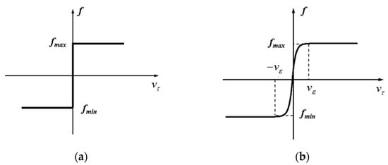
Figure 5.
Friction model: (a) Coulomb friction model and (b) improved Coulomb friction model.
Because the Coulomb friction model is not continuous, the model is singular when the tangential velocity is zero, and it is difficult to converge in a simulation calculation. In order to solve the shortcomings of the Coulomb friction model, scholars have proposed many improved Coulomb friction models [28,29]. In the above model, it is considered that the actual friction coefficient is closely related to parameters such as the tangential velocity.
where represents the actual friction coefficient, and represents the transition velocity independent of friction force and tangential velocity.
Then, the improved Coulomb friction model can be described by Equation (10).
The friction force of the improved Coulomb friction model is shown in Figure 5b.
3.1.3. Rigid–Flexible-Coupling Model of Landing Gear Retraction Mechanism
The instability of the DSS retraction mechanism is more prominent at the moment of landing gear locking and unlocking, and it is difficult for the pure rigid body to achieve the normal landing gear unlocking. Therefore, it is necessary to consider the structural flexibility characteristics of the landing gear and make some components flexible. The material used for each part of the flexible body is alloy steel, with an elastic modulus of 200 MPa, a Poisson ratio of 0.3, and a density of 7.9 g/cm3.
- In the HyperMesh 2021 finite element analysis software, the finite element mesh of each component to be flexible is established, and the corresponding material properties are given. The MPC point is established at the constraint connection, the boundary conditions are defined, and the flexible file is derived.
- The flexible file is imported into the LMS Virtual.Lab software, and the Nastran Craig–Bampton modal set is established, respectively. The modal information of each flexible component is calculated by NX.Nastran for LMS 8.5 software, the first six free modes are cancelled, the last ten modes are selected, and the corresponding modal damping rate is given.
- The flexible and rigid components are assembled into a complete model in LMS Virtual.Lab, and the rigid–flexible-coupling dynamic simulation model of the DSS landing gear is obtained, as shown in Figure 6.
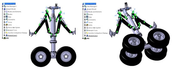 Figure 6. Rigid–flexible-coupling dynamic simulation model.
3.2. Synchronous Locking Test of Dual-Sidestay Landing Gear
According to the retraction principle and design requirements of the DSS landing gear, a scaled-down prototype model for the synchronous locking test was built by CATIA V5R21. Each component of the prototype was processed according to the design drawings. Considering the sensitivity of the DSS landing gear to structural parameters, a reasonable assembly tolerance and processing technology were designed to meet the stringent design requirements of the “four axes intersecting at one point” of the 3D retraction mechanism. After production and processing, the prototype parts that meet the test requirements were obtained. The assembly of the components resulted in the DSS landing gear test platform shown in Figure 7.
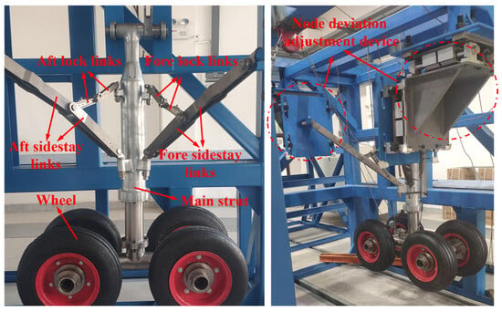
Figure 7.
Physical schematic diagram of DSS landing gear test platform.
During the flight of an aircraft, deformation of the wing or the assembly deviation of the nodes may cause the installation node position of the upper sidestay nodes to deviate from the initial position. To simulate the impact of the node deviation of the DSS landing gear under real conditions on the synchronous locking performance of the landing gear, this experiment designed a node deviation simulation device, as shown in Figure 8. This device is composed of components such as trapezoidal screws, screw nuts, and linear guide-rail guide sliders. Due to the good self-locking property of the trapezoidal screws, they can conveniently adjust and lock the deviation of the installation node in the flight direction (X direction) and the vertical direction (Z direction).
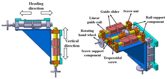
Figure 8.
Node deviation simulation device.
The data measured in the test include the extension time, the retraction angle of the landing gear, the motion angle of the fore and aft lock links, and the retraction torque. Voltage-positioned angle sensors were selected to measure the over-center angle of the fore and aft lock links of the landing gear (Figure 9a) and the retraction angle of the main strut (Figure 9b). The retraction torque can be measured by the load sensor installed on the steel wire rope to measure the load on the rope. Finally, the DH5902 dynamic signal test system was used to collect the test data and perform fitting to obtain the relevant test result curves. The test process is shown in Figure 10.
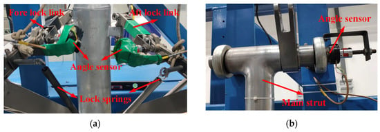
Figure 9.
Angle data collection method: (a) installation of over-center angle sensors and (b) installation of retraction angle sensors.
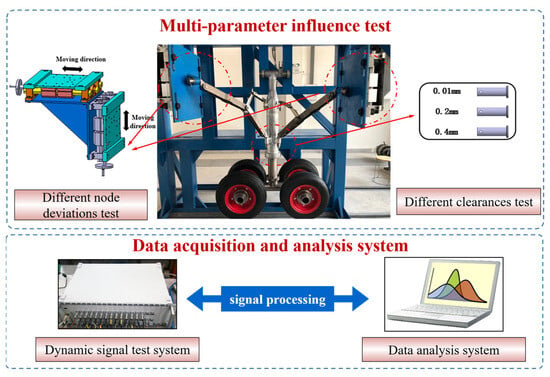
Figure 10.
Multiparameter influence test process.
3.3. Comparison of Simulation and Test Results
A comparison of the test results and the dynamic simulation data is shown in Figure 11. Among the results, represents the fore lock link over-center angles, represents the aft lock link over-center angles, and Mact represents the retraction torque. The simulation curves of the fore and aft lock links over-center angles with respect to the extension time basically coincide with the experimental curves. The curves of the fore and aft lock link over-center angles with respect to the retraction torque exhibit a small difference near the jump lock because, after the lock link crosses the critical position, the locking action is quickly completed. Under the effect of damping, the retraction torque is greater than that in the simulation data.
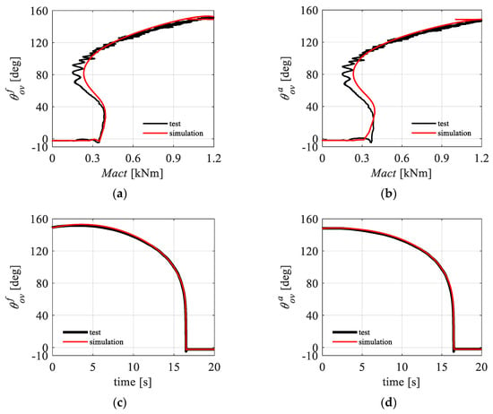
Figure 11.
Comparison of simulation and test results: (a) curve; (b) curve; (c) curve; and (d) curve.
4. Multiparameter Impact Analysis
4.1. Analysis of the Impact of Node Deviation
Due to wing deformation or errors during installation and machining, the nodes of the DSS landing gear may have a certain deviation relative to the design position. It is necessary to study the influence of hinged point deviation on synchronous locking for the over-constrained DSS mechanism. The deviation models in the X direction (heading) and Z direction (vertical) are established at the characteristic points of the axis of the hinge point. The deviation direction of the hinge point is shown in Figure 12. In the simulation and test, the deviation distance generated by moving along the X direction and Z direction, respectively, is used to stagger the position of the original four-line common point.
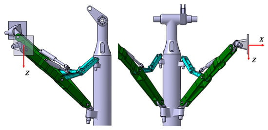
Figure 12.
Definition of node deviation direction.
4.1.1. Analysis of Simulation Results
Based on the rigid–flexible-coupling dynamic simulation model considering joint clearance and node deviation, the deviations of the installation nodes of the fore and aft sidestays in the X direction and Z direction are simulated. The deviation range in each direction that can satisfy the complete locking of the landing gear is obtained. As shown in Table 1, the deviation range of the fore sidestay installation node in the X direction is (−20 mm, 19 mm), the Z direction deviation range is (−17 mm, 18 mm), the deviation range of the aft sidestay installation node in the X direction is (−20 mm, 19 mm), and the deviation range in the Z direction is (−16 mm, 16 mm).

Table 1.
Range of the node deviations in different directions.
The simulation analysis indicates that the synchronous locking performance of the landing gear has different sensitivities to node deviations in different directions. The sensitivity to the Z direction of the aft sidestay node deviation is the largest, and the sensitivity to the X direction of the fore sidestay node deviation is the smallest. However, the influence rules of node deviation in different directions on the motion trajectory and load transfer characteristics of the landing gear are very similar. Therefore, the following takes only the installation deviation of the fore sidestay node in the X direction (using to represent it) as an example to investigate the influence of node deviation on the synchronous locking performance of the landing gear and sets the node deviation conditions from −20 mm to 19 mm. The simulation results are shown in Figure 13. The definition of related variables is the same as above; in addition, represents the load of the fore sidestay node, represents the load of the aft sidestay node, represents the load of the fore lock node, and represents the load of the aft lock node.
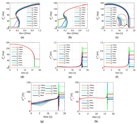
Figure 13.
Node deviation simulation curves: (a) curve; (b) curve; (c) curve; (d) curve; (e) curve; (f) curve; (g) curve; and (h) curve.
As shown in Figure 13a,b, when there is no deviation of the nodes, the lock links on both sides are locked almost synchronously. With a gradual increase in the deviation of the fore sidestay node in the positive X direction, the locking behavior of the aft lock link gradually lags until it cannot be completed (fX = 19 mm); as the deviation in the negative X direction gradually increases, the locking behavior of the fore lock link gradually lags until it cannot be fully locked (fX = −20 mm). Notably, near the locking position, there is a jump mutation process in the lock link. When the positive deviation is larger, the angle of the fore lock link at the time of the jump will decrease, and the jump angle of the aft lock link will increase.
As shown in Figure 13c,d, the deviation of the fore sidestay node in the X direction affects mainly the motion trajectory of the fore sidestay system and has a smaller impact on the motion trajectory of the aft sidestay system. Positive deviation of the fore sidestay node in the X direction causes the aft lock links to lock up late, while the fore lock links lock normally, so the synchronicity of the landing gear lock deteriorates as the node deviation increases.
As shown in Figure 13e–h, in terms of load transmission characteristics, different node deviations correspond to roughly the same trend of load changes at the joints of the lock links and sidestay links. During the extension process, the change in node load is relatively smooth, until near the locking position, when the sidestay node load rapidly mutates, while the lock node load rises only slightly.
However, in terms of load transmission characteristics, the deviation of the fore sidestay node in the X direction has a greater impact on the load of the fore sidestay node and a smaller impact on the load of the aft sidestay node and the fore and aft lock nodes. For the fore sidestay node, the node deviation not only affects the angle at which the load peak appears but also increases the peak value.
4.1.2. Analysis of Test Results
According to the test design, the synchronous locking performance of the landing gear is verified by changing the deviation values of the fore and aft sidestay nodes in the X direction and Z direction. Here, the deviation of the fore sidestay node is taken as an example to introduce the rule of parameter influence. In the test, set the node deviation conditions to 0 mm, ±5 mm, ±10 mm, +22 mm (maximum limit value), and −21 mm (minimum limit value), among which 0 mm is a reference. In the test, only one unidirectional deviation of one node is adjusted for each working condition. The limit deviation condition is obtained by changing the node deviation slowly. The collected test results are shown in Figure 14.
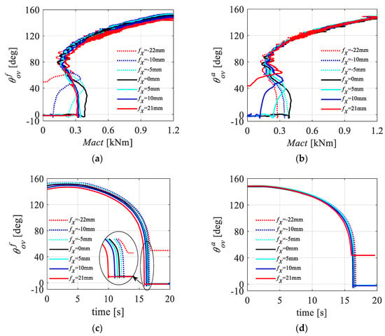
Figure 14.
Node deviation test results: (a) curve; (b) curve; (c) curve; and (d) curve.
As shown in Figure 14c,d, the deviation of the fore sidestay node in the X direction affects mainly the fore lock link and has a smaller impact on the aft lock link. When the node deviation value is small, the lock links on both sides are locked almost synchronously (as shown in Figure 15). With the increase in the deviation, the locking time of the lock links on two sides is obviously asynchronous (as shown in Figure 16, the aft lock link gradually lags). As the deviation value continues to increase, when fX = −22 mm, the fore lock link cannot be fully locked, and when fX = 21 mm, the aft lock link cannot be fully locked (as shown in Figure 17). Compared with the simulation analysis results, the overall range is expanded by approximately 1 mm, which shows that the actual DSS landing gear prototype has a higher tolerance for node deviation than the simulation model does and that the conditions required for synchronous locking are easier to achieve. The change law of the test results is similar to that of the simulation results, thus effectively verifying the accuracy of the simulation model for the impact of node deviation.
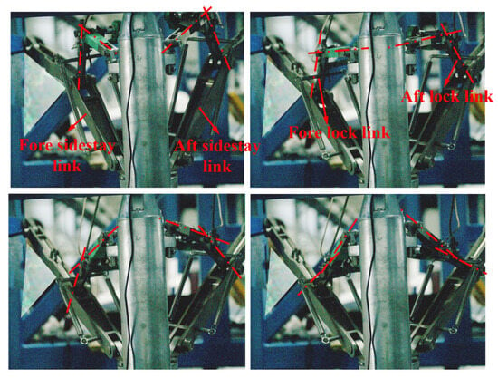
Figure 15.
Schematic diagram of synchronous locking on both sides of the lock links.
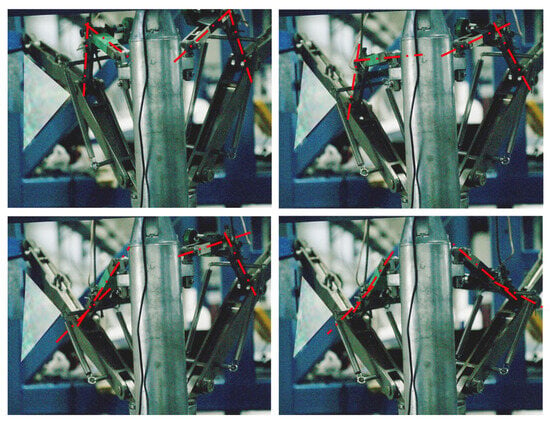
Figure 16.
Schematic diagram of the lag locking of the aft lock links.
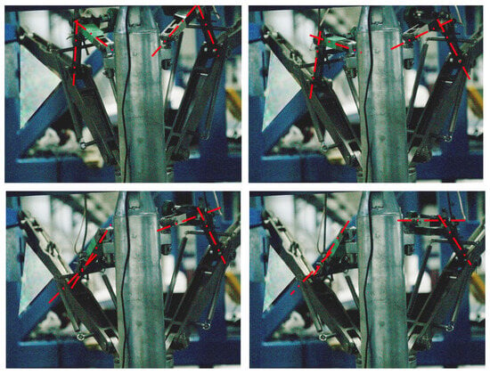
Figure 17.
Schematic diagram of the aft lock links that cannot be locked.
According to the above methods, more simulations and tests were carried out, and the influence of different node deviations on the locking ability of the fore and aft lock links is shown in Table 2.

Table 2.
Comparison of simulation and test results of node deviation range.
4.2. Analysis of the Impact of Joint Clearance
4.2.1. Analysis of Simulation Results
For the fully rigid ideal hinge mechanical model, the DSS landing gear can hardly be fully locked. However, the interaction of the hole–shaft clearance and the rigid–flexible-coupling model will greatly improve the synchronous locking performance of the landing gear. By using dynamic simulation software to analyze the impact of different clearance conditions on the synchronous locking performance of the fore and aft sidestay systems of the DSS landing gear, the clearance adjustment amounts are set to 0 mm, 0.1 mm, 0.2 mm, and 0.4 mm, with the 0 mm condition serving as the reference. The simulation results in Figure 18 indicate that the joint clearance has a small impact on the synchronous locking performance of the landing gear. In terms of the load transfer characteristics, the load of the fore lock node decreases slightly during the landing gear extension process as the joint clearance increases.
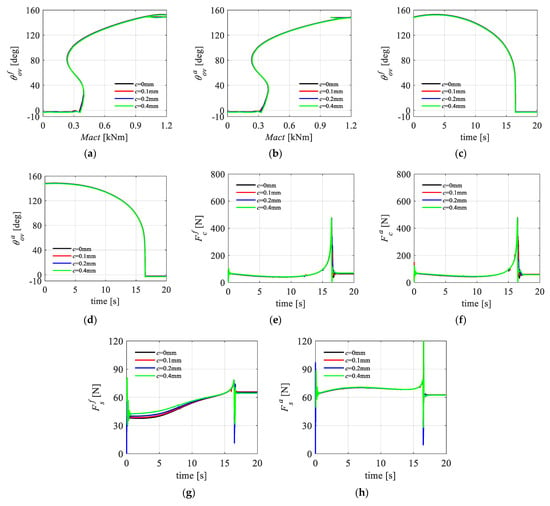
Figure 18.
Joint clearance simulation curves: (a) curve; (b) curve; (c) curve; (d) curve; (e) curve; (f) curve; (g) curve; (h) curve.
4.2.2. Analysis of Test Results
According to the test design, the influence of joint clearance can be obtained by replacing different diameter pins. The clearance adjustment amounts are set to 0 mm, 0.2 mm, and 0.4 mm, with the 0 mm condition serving as the reference. When the clearance amount is adjusted, both sides of the sidestay link are adjusted at the same time. The test results are shown in Figure 19.
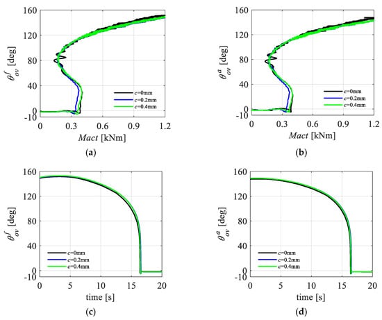
Figure 19.
Joint clearance test results: (a) curve; (b) curve; (c) curve; and (d) curve.
The test results show that the increase in joint clearance has little effect on the synchronous locking ability of the landing gear during the slow extension process, which is consistent with the results of the previous analysis.
Although the joint clearance has a small impact on the synchronous locking performance and load transfer characteristics of the landing gear, it affects the limit node deviation range where the landing gear can completely lock in all directions. Taking the deviation of the fore sidestay node in the X direction as an example, the node deviation ranges corresponding to different joint clearances are shown in Table 3. The larger the joint clearance is, the greater the range in which the lock links can be completely locked. This indicates that, for mechanisms with a poor synchronous locking performance, appropriately increasing the joint clearance can improve their locking performance. However, excessive clearance will cause severe wear between the mechanisms, affecting the service life. Therefore, the size of the joint clearance of the mechanism should be reasonably designed according to actual engineering needs.

Table 3.
Limit range of the fore sidestay node deviation in the X direction corresponding to different clearances that lock links on both sides can be completely locked.
5. Conclusions
Aiming at addressing the high motion sensitivity of the DSS landing gear mechanism during the retraction movement and the lack of related analyses of the joint clearance and installation deviation of the retraction mechanism in the traditional dynamic modeling method, this paper focuses on the 3D DSS main landing gear (MLG) retraction mechanism suitable for wide-body aircraft. By using HyperMesh/Nastran and LMS Virtual.Lab Motion, a rigid–flexible-coupling dynamic simulation model considering hole–shaft clearance and node installation deviation is established based on the continuous contact force model and modified Coulomb friction model. A DSS retraction mechanism cooperative locking test platform is set up, and the accuracy of the simulation model is verified through relevant tests. Based on this model, the influence of key parameters, such as installation node deviation and joint clearance, on the cooperative locking performance of the landing gear are studied in detail. The main conclusions are as follows:
- In actual engineering, the hole–shaft clearance at the structural joint can eliminate the adverse effects caused by the deformation of the wing structure to a certain extent. Therefore, within a reasonable design range, this hyperstatic 3D retraction mechanism can successfully complete the retraction process without following the principle of “four axes intersecting at one point” and will not have a great impact on the final analysis results.
- An increase in node deviation makes the synchronous locking of the lock links on both sides more difficult. The sensitivity of the aft sidestay node deviation in the Z direction is the largest, and the sensitivity of the fore sidestay node deviation in the X direction is the smallest. Node deviation has a greater impact on the joint load of the sidestay node on the side of the adjusted deviation, mainly affecting its peak load and the position of the peak, and has a small impact on the remaining joint loads.
- Through a simulation analysis, the limit range of the fore and aft sidestay node deviation in different directions that can satisfy the complete locking of lock links on both sides is obtained. The deviation range of the fore sidestay node in the X direction is (−20 mm, 19 mm), and in the Z direction, it is (−17 mm, 18 mm); and the deviation range of the aft sidestay node in the X direction is (−20 mm, 19 mm), and in the Z direction, it is (−16 mm, 16 mm).
- For mechanisms with good a cooperative locking performance, during the slow extension process of the landing gear, the joint clearance has a very small impact on the retraction trajectory and joint load of the mechanism, and the general trend is that the load of the lock node and retraction torque decrease slightly as the joint clearance increases. Although appropriately increasing the joint clearance can increase the node deviation range corresponding to the complete locking of the DSS retraction mechanism, its size should be controlled strictly to avoid frequent collisions and severe vibrations of structural parts.
- The simulation results are in good agreement with the test results. The only difference is that the Mact in the simulation results is smaller than that in the test results when the lock links jump rapidly. The influence trend of the parameters on the synchronous locking is basically similar to the simulation conclusion. The difference is that the limit range of the node deviation measured by the test is larger. It is proved that the continuous contact force model and modified Coulomb friction model are suitable for the clearance modeling of the landing gear retraction mechanism. This modeling method can be applied to the design and analysis of the landing gear mechanism of wide-body aircraft.
Recommendations for future research: This paper studies only the effect of clearance and node deviation on the synchronous locking performance of DSS landing gear. In the future, the hydraulic system and control system can be incorporated to study the retractable and unlocking performance of DDS landing gear.
Author Contributions
Conceptualization and methodology, Z.Z. and. S.W.; validation, Z.Z. and S.W.; formal analysis, Z.Z. and H.Z.; investigation, H.Z., H.N. and X.W.; resources, H.N. and X.W.; writing—original draft preparation, Z.Z. and S.W.; writing—review and editing, Z.Z. and H.Z.; visualization, Z.Z. and S.W.; project administration, H.Z. and H.N. All authors have read and agreed to the published version of the manuscript.
Funding
This research was funded by the National Natural Science Foundation of China (He Zhu, No. 52202443; Hong Nie, No.52275114), China Postdoctoral Science Foundation (He Zhu, 2023M731656), National Key Laboratory of Helicopter Aeromechanics Foundation (He Zhu, 2023-HA-LB-067-05e), Natural Science Foundation of Jiangsu Province (He Zhu, No. BK20220898), Jiangsu Funding Program for Excellent Postdoctoral Talent (He Zhu, No. JB0202003), and Aeronautical science foundation of China (He Zhu, No. 20232010052002).
Institutional Review Board Statement
Not applicable.
Informed Consent Statement
Not applicable.
Data Availability Statement
The data presented in this study are available upon request from the first author.
Conflicts of Interest
The authors declare no conflict of interest.
References
- Tartaruga, I.; Cooper, J.E.; Lowenberg, M.H.; Lemmens, Y. Enhanced Evolutionary-Based Optimization Techniques Applied to a Nonlinear Landing Gear Design Problem. J. Aircr. 2019, 56, 2004–2018. [Google Scholar] [CrossRef]
- Currey, N.S. Aircraft Landing Gear Design: Principles and Practices; AIAA: Washington, DC, USA, 1988. [Google Scholar]
- Parat, C.; Li, Z.; Zhao, J.-S. Design and stiffness analysis of an overconstrained landing gear retraction mechanism with four side-stays. Proc. Inst. Mech. Eng. Part G J. Aerosp. Eng. 2019, 233, 4421–4435. [Google Scholar] [CrossRef]
- Parat, C.; Li, Z.; Zhao, J. Design and Folding/Unfolding Dynamics of an Over-Constrained Airplane’s Landing Gear With Four Side Stays. J. Mech. Robot. 2019, 11, 011001. [Google Scholar] [CrossRef]
- Tinoco, E.N.; Brodersen, O.P.; Keye, S.; Laflin, K.R.; Feltrop, E.; Vassberg, J.C.; Mani, M.; Rider, B.; Wahls, R.A.; Morrison, J.H.; et al. Summary Data from the Sixth AIAA CFD Drag Prediction Workshop: CRM Cases. J. Aircr. 2017, 55, 1352–1379. [Google Scholar] [CrossRef]
- Veaux, J. New design procedures applied to landing gear development. J. Aircr. 1988, 25, 904–910. [Google Scholar] [CrossRef]
- Yin, Y.; Nie, H.; Ni, H.J.; Zhang, M. Reliability Analysis of Landing Gear Retraction System Influenced by Multifactors. J. Aircr. 2016, 53, 713–724. [Google Scholar] [CrossRef]
- Luo, H.T.; Zhao, J.S. Synthesis and kinematics of a double-lock overconstrained landing gear mechanism. Mech. Mach. Theory 2018, 121, 245–258. [Google Scholar] [CrossRef]
- Knowles, J.A.C.; Krauskopf, B.; Lowenberg, M. Numerical continuation analysis of a three-dimensional aircraft main landing gear mechanism. Nonlinear Dyn. 2013, 71, 331–352. [Google Scholar] [CrossRef][Green Version]
- Gao, C. Civil Aircraft Main Landing Gear Single Stay and Dual Stay Trade Off. Sci. Technol. Vis. 2017, 4, 2095–2457. [Google Scholar]
- Xu, K.; Yin, Y.; Yang, Y.; Nie, H.; Wei, X. Bifurcation analysis of dual-sidestay landing gear locking performance considering joint clearance. Chin. J. Aeronaut. 2022, 35, 209–226. [Google Scholar] [CrossRef]
- Fan, G.J.; Yuan, L.; Lu, L.J.; Jiang, B.Y. Kinematic Analysis of Landing Gear Spatial Retractable Mechanism. J. Zhengzhou Univ. (Eng. Sci.) 2012, 33, 88–92. [Google Scholar]
- Tian, J.J.; Jia, Y.H. Modeling and Simulation of Large Civil Aircraft Landing Gear System. Mach. Des. Manuf. 2016, 5, 48–52. [Google Scholar] [CrossRef]
- Cui, F.; Ma, D.L. Simulation analysis on dynamic performance of landing gear based on LMS Virtual. Lab. Comput.-Aided Eng. 2012, 21, 25–29. [Google Scholar]
- Huang, F.L.; Li, S.; Wang, Y.D. Study of Mechanical Efficiency of a Civil Aircraft’s Three Dimensional Landing Gear Operation Mechanism. J. Vib. Meas. Diagn. 2013, 33 (Suppl. S1), 188–191+230. [Google Scholar]
- Krakowska, A. Design of retraction mechanism of aircraft landing gear. Mech. Mech. Eng. 2008, 12, 357–373. [Google Scholar]
- Xin, Y.; Chen, X.J. Load design of landing gear brace lock spring of a new type civil aircraft. Mach. Des. Manuf. Eng. 2021, 50, 63–67. [Google Scholar]
- Knowles, J.A.C.; Krauskopf, B.; Lowenberg, M.H. Numerical Continuation Applied to Landing Gear Mechanism Analysis. J. Aircr. 2011, 48, 1254–1262. [Google Scholar] [CrossRef][Green Version]
- Yin, Y.; Neild, S.A.; Jiang, J.Z.; Knowles, J.A.C.; Nie, H. Optimization of a Main Landing Gear Locking Mechanism Using Bifurcation Analysis. J. Aircr. 2017, 54, 2126–2139. [Google Scholar] [CrossRef]
- Chinvorarat, S.; Vallikul, P. A novel retractable landing gear of a light amphibious airplane design, synthesis, analysis, and implementation. Aircr. Eng. Aerosp. Technol. 2021, 93, 1547–1558. [Google Scholar] [CrossRef]
- Knowles, J.A.C.; Krauskopf, B.; Lowenberg, M.H.; Neild, S.A.; Thota, P. Numerical Continuation Analysis of a Dual-Sidestay Main Landing Gear Mechanism. J. Aircr. 2014, 51, 129–143. [Google Scholar] [CrossRef][Green Version]
- Erkaya, S.; Uzmay, İ. Investigation on effect of joint clearance on dynamics of four-bar mechanism. Nonlinear Dyn. 2009, 58, 179–198. [Google Scholar] [CrossRef]
- Erkaya, S.; Doğan, S. A comparative analysis of joint clearance effects on articulated and partly compliant mechanisms. Nonlinear Dyn. 2015, 81, 323–341. [Google Scholar] [CrossRef]
- Zhang, Z.L.; Wu, S.J.; Zhao, W.Q.; Wang, X.S. Dynamic characteristics of high-speed multi-link transmission mechanisms with clearance. J. Vib. Shock 2014, 33, 66–71. [Google Scholar]
- Yin, Y.; Xu, K.; Nie, H.; Wei, X.H.; Wang, H.L. Dynamics Analysis of Spatial Landing-Gear Mechanism with Hinge Clearance and Axis Deviation. J. Aircr. 2020, 58, 30–42. [Google Scholar] [CrossRef]
- Yan, S.Z.; Xiang, W.W.; Huang, T.Q. Advances in Modeling of Clearance Joints and Dynamics of Mechanical Systems with Clearances. Acta Sci. Nat. Univ. Pekin. 2016, 52, 741–755. [Google Scholar]
- Lankarani, H.M.; Nikravesh, P.E. A Contact Force Model With Hysteresis Damping for Impact Analysis of Multibody Systems. J. Mech. Des. 1990, 112, 369–376. [Google Scholar] [CrossRef]
- Rooney, G.T.; Deravi, P. Coulomb friction in mechanism sliding joints. Mech. Mach. Theory 1982, 17, 207–211. [Google Scholar] [CrossRef]
- Ambrósio, J.A.C. Impact of Rigid and Flexible Multibody Systems: Deformation Description and Contact Models. In Virtual Nonlinear Multibody Systems; Schiehlen, W., Valášek, M., Eds.; Springer: Dordrecht, The Netherlands, 2003; pp. 57–81. [Google Scholar]
Disclaimer/Publisher’s Note: The statements, opinions and data contained in all publications are solely those of the individual author(s) and contributor(s) and not of MDPI and/or the editor(s). MDPI and/or the editor(s) disclaim responsibility for any injury to people or property resulting from any ideas, methods, instructions or products referred to in the content. |
© 2024 by the authors. Licensee MDPI, Basel, Switzerland. This article is an open access article distributed under the terms and conditions of the Creative Commons Attribution (CC BY) license (https://creativecommons.org/licenses/by/4.0/).