Article

Multi-Objective Optimization Design of an Origami-Inspired Combined Cushion Airbag

1
School of Aeronautics and Astronautics, Zhejiang University, Hangzhou 310027, China
2
School of Mechanics Civil Engineering and Architecture, Northwestern Polytechnical University, Xi’an 710072, China
3
Shanghai Institute of Aerospace System Engineering, Shanghai 201108, China
*
Author to whom correspondence should be addressed.
Aerospace 2024, 11(3), 169; https://doi.org/10.3390/aerospace11030169
Submission received: 30 November 2023 / Revised: 4 February 2024 / Accepted: 13 February 2024 / Published: 20 February 2024
(This article belongs to the Special Issue Deployable Space Structures and Mechanisms)

Abstract

:
To improve the cushioning performance of soft-landing systems, a novel origami-inspired combined cushion airbag is proposed. The geometry size, initial pressure, and exhaust vent area of the cushion airbags are designed preliminarily using a theoretical model. The finite element models, including the returnable spacecraft and cushion airbags, are established via the control volume method (CVM) to analyze the impact dynamic behavior and cushioning performance during the landing attenuation process. The cushioning performance of the cushion airbags in complex landing environments are studied to investigate the influence of horizontal velocity, lateral velocity and nonhorizontal landing surfaces. Four design parameters of the cushion airbags, including the initial pressure, venting threshold pressure, exhaust vent area and polygon edge number, are employed to study their influence on the cushioning performance. A multi-objective optimization model of the cushion airbags based on the neural network and multi-objective water cycle algorithm is established to realize the rapid optimization design. The Pareto front of the maximum overload and specific energy absorption is obtained. The analysis results show that the maximum overload of the proposed combined cushion airbags is 7.30 g. The system with the anti-rollover design can avoid rollover and achieve outstanding cushioning performance in complex landing environments. The maximum overload of the returning spacecraft is decreased by 16.4% from 7.30 g to 6.10 g after multi-objective optimizations. This study could provide the technical support for the soft-landing system design of returnable spacecrafts.

1. Introduction

Many space missions, such as human spaceflights and deep space explorations, require the landing, sampling and return tasks of probes on the surface of planet. Due to the advantages of foldability, reusability, light weight, high reliability and superior cushioning performance, cushion airbags are applied as one of landing buffer devices for many returnable spacecrafts. The cushion airbag is an inflatable structure that utilizes the elastic deformation of flexible materials, compression of internal gas, and gas exhausting to absorb the kinetic energy of a returnable spacecraft during the landing attenuation process, achieving deceleration, reducing impact overload, and protecting returnable spacecrafts [1,2].
According to the working mechanism, cushion airbags can be classified as three types: sealed airbags, vented airbags, and combined airbags. Combined airbags are the most widely used. Both ILC Dover and Airborne Systems North America have designed the cushioning airbag system for the Crew Exploration Vehicle (CEV) [3,4] by using combined airbags. This system is composed of several combined airbags, all of which exhibit excellent cushioning performance to achieve functions such as deceleration, reducing impact overload and avoiding the problems of tipping and sinking. The ExoMars Mars probe of the European Space Agency (ESA) [5] has also adopted the combined airbag scheme in which the main airbag is divided into six chambers. Each chamber is equipped with a closed annular airbag for providing elastic support to avoid the spacecraft from collision with the ground directly.
Due to the high cost of experimental research on cushion airbags, numerical simulation methods, such as the finite element method, are primarily utilized to evaluate cushioning performance and feasibility in the preliminary design stage of the cushion airbags. Wang et al. [6] proposed the control volume method (CVM) and applied it to the deployment and force analysis of airbags. He et al. [7] utilized the independence of the structure finite element model from the full impact finite element model to develop a hierarchical updating scheme for the FE model of the recovery module and airbag system. Wang et al. [8] established a finite element model of a vehicle with its airbag system and conducted experimental verification. Zhou et al. [9] proposed a new direct modeling method for cylindrical cushion airbags and verified the correctness of the method via finite element analysis. Dmitri et al. [10] simulated the Body Block Test (BBT) by using the Arbitrary Lagrange–Euler Method (ALEM) and CVM.
In recent years, origami technology has been widely applied in the structural designs of metal thin-walled energy absorbers [11,12,13]. It has been stated that the metal thin-walled tube as the basis of origami structural designs can increase the plastic hinge line and reduce the critical buckling load, thereby changing its static and buckling deformation modes and ultimately improving energy absorbing performance [14]. Liu et al. [15] designed a square-section thin-walled tube based on a diamond origami pattern and studied its axial impact performance by using an explicit finite element analysis method. Yuan et al. [16] designed a series of new origami collision boxes with rectangular, polygonal, and conical cross-sections based on the pre-folded surface of thin-walled tubes inspired by a set of origami patterns. Yang et al. [17] proposed three new multicell tubular structures with pre-folded origami patterns to study the influence of geometric parameters on mechanical properties through finite element analyses. At present, origami technology is rarely applied in the design of soft-landing cushion airbags. Therefore, it is necessary to study the deformation mode and cushioning performance of the cushion airbags by introducing the origami design.
To improve the cushioning performance of traditional cushion airbags, this study employs origami technology to design a combined cushion airbag and conducts a multi-objective optimization design of this combined cushion airbag. The feasibility of this novel combined cushion airbag in complex landing environments is explored. The remainder of this paper is organized as follows: The design scheme and theoretical model of the combined cushion airbag are described in Section 2. Finite element analysis models for cushioning performance are established in Section 3. Section 4 evaluates the feasibility of the combined cushion airbags in complex environments. The influence mechanism of the design parameters on cushioning performance is studied in Section 5. The multi-objective optimization method and results of the cushion airbags based on the neural network and multi-objective water cycle algorithm are described. Finally, Section 6 summarizes a few concluding remarks and suggestions for future works.

2. Design of Combined Cushion Airbag

The cushioning performance of cushion airbags needs be explored during the landing attenuation process of a returnable spacecraft back to Earth. Thus, it is necessary to consider the aerodynamic shape of a returnable spacecraft in the design of cushion airbags. The cushioning airbag system set on the bottom of a returnable spacecraft (as shown in Figure 1a) is composed of five combined airbags. Each combined airbag shown in Figure 1b is the combination of a sealed airbag above and a vented airbag below. During the landing attenuation process, the sealed airbag can ensure that there is an airbag between the returnable spacecraft and the ground to achieve a soft landing, while the vented airbags with exhaust vents on the side walls can dissipate the impact energy. The novel airbag inspired by origami design is introduced here with the layouts displayed in Figure 1b–d. The sidewalls of all airbags adopt the Yoshimura origami pattern shown in Figure 1b. Two adjacent airbags are connected at the vertices of the Yoshimura origami pattern, such as A, B, C and D in Figure 1b, to make these five combined airbags work together.
The mass of the returnable spacecraft is defined as M = 300 kg. The ratio of the returnable spacecraft mass to the cushion airbag volume is generally 1000~1100 kg/m3 [18]. The internal pressure of the cushion airbags here is designed as the standard atmospheric pressure of 101 kPa because it is used for the returnable spacecraft back to Earth.

2.1. Design of Airbag Height

The kinetic energy of a returnable spacecraft is generally dissipated by the elastic deformation of flexible materials, compression of internal gas, and gas exhausting of the cushion airbags, which are affected by the cushioning stroke s and height h of the cushion airbags. The difference in kinetic energy E k of the returnable spacecraft is defined as
E k = 1 2 M v 1 2 v 2 2
where M is the mass of the returnable spacecraft. v 1 and v 2 are the velocities of the returnable spacecraft before and after landing, respectively.
During the landing attenuation process, the reaction force F of the cushion airbags on the returnable spacecraft is highly non-linear as a function of the cushioning stroke s . This reflects the complex interactions and deformations of the airbags during the landing attenuation process. The work WF performed by the reaction force F can be obtained by integrating the force over the cushioning stroke s , W F = F s d s . If the acceleration of the returnable spacecraft is at its allowable maximum value a during the landing attenuation process, the possible work of the reaction force F s takes its maximum value N M g s , where N = a / g indicates the maximum overload that the spacecraft can sustain, and g is the gravitation acceleration. Thus, the actual work W F performed by the reaction force F can be expressed as
W F = N M g s η
where η is the efficiency of the cushion airbags, representing the ratio of the actual work conducted by the reaction force to the maximum possible work.
Based on the principle of the conservation of energy, the actual work WF performed by the reaction force F from the airbags equates to the total mechanical energy dissipation of the returnable spacecraft. This dissipation includes both the change in kinetic energy E k and the change in gravitational potential energy M g s . There is
W F = E k + M g s
It is fully demonstrated that the kinetic energy of a returnable spacecraft is absorbed by utilizing the compression of internal gas and gas exhausting during the landing attenuation process without considering the plastic deformation dissipation of airbag material. Thus, the cushioning stroke s   can be obtained by Equations (1)–(3):
s = v 1 2 v 2 2 2 g N η 1
For a combined cushion airbag with exhaust vents when it is completely folded, the height h of the airbags is designed to be larger than this cushioning stroke s in the final configuration, with speed v 2 = 0 as
h = v 1 2 i 2 g N η 1
where i is the design safety factor, which is generally chosen as 2.0.

2.2. Design of the Exhaust Vent

The exhaust vent is blocked initially while it is opened by the increasing internal pressure of the compressed airbags during the landing attenuation process. To achieve a completely folded state as mentioned above, the exhaust vent area A o u t of the combined airbag is a key design parameter that affects its cushioning performance. It is expressed as [19]
A o u t = v 1 A Q R T
where A is the bottom area of the airbags, the unit of which is m2; Q is the flow coefficient of the exhaust vent, which is a dimensionless coefficient; R is the gas parameter, which is 8.314 J/(mol · K); and T is the temperature of the gas inside the airbags, the unit of which is K.

2.3. Origami Pattern Design

Based on the Yoshimura origami pattern [20] of the combined cushion airbags in Figure 1b, the basic units are two isosceles triangles (namely, triangles ABD and CBD). Then, the cross-section of the airbags can be extended circumferentially into an L polygon and extended along the axial direction into the specified number J of the layer. The hypotenuses AB and AD of isosceles triangle ABD are defined as b , while the bottom edge BD is defined as c . Thus, the bottom edge c and height h c on this bottom edge can be expressed based on the bottom angle ABD ( θ ) and b as
c = 2 b cos θ , h c = b sin θ
The radius r of the section’s circumscribed circle is expressed as
r = c 2 sin π L
Then, the airbag height h of the cushion airbag is written as
h = 2 J h c sin α 2 = J h 0
where α is defined as the dihedral angle between triangles ABD and CBD, and h 0 is the height of each layer.
Therefore, if the axial layer J , polygon edge number L and circumscribed circle radius r are determined, the geometric configuration for the origami-inspired cushion airbags can be obtained.

3. Finite Element Modeling and Analysis

To verify the cushioning performance of the origami-inspired cushion airbags, a finite element model is established and impact dynamic simulations are conducted based on the CVM in the software LS-DYNA R12.0.0. CVM, verified by previous experiment studies, has been widely applied in the numerical simulation of traditional cushion airbags [21,22]. The effectiveness of CVM and complex FE analysis models of the cushion airbag system is verified in Supporting Information Note S1.

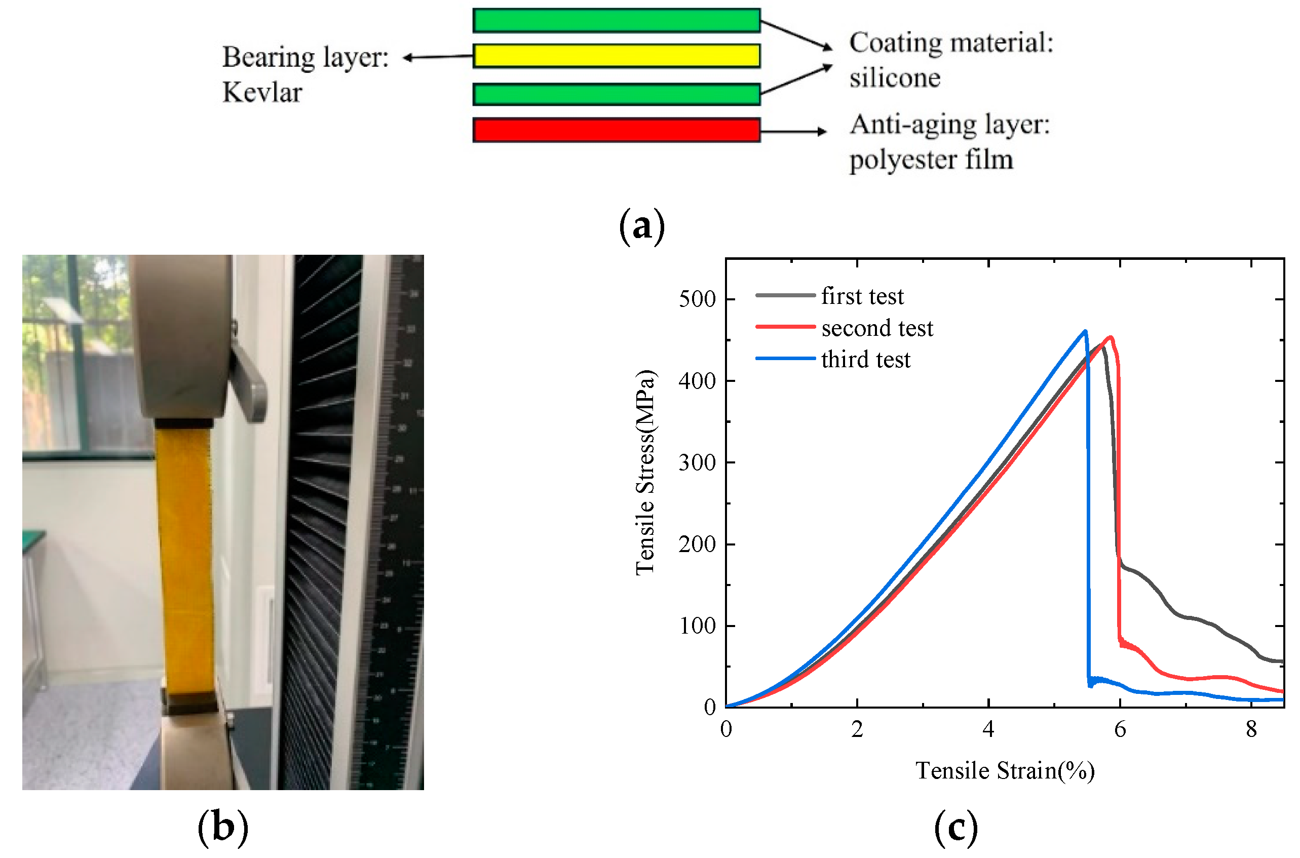
3.1. Material Design and Test

Since the cushion airbags are subject to a high impact load during the landing attenuation process, the material of cushion airbags is required to have high strength. In addition, the material is required to be light weight and have strong aging resistance and friction resistance. Thus, the material is designed to be a multi-layer flexible material. The outermost anti-aging and sealing layer is polyester film, the bonding layer is a silicone coating, and the innermost bearing layer is Kevlar fabric, as shown in Figure 2a.
To obtain the material properties for the cushion airbags, three test pieces of this material are fabricated to complete the uniaxial tensile tests. The test piece models are designed with a length of 140 mm, a width of 25 mm and a thickness of 0.2 mm, as shown in Figure 2b. The uniaxial tensile tests are carried out on an HF-9002 computerized tensile testing machine three times to obtain the stress–strain curves as shown in Figure 2c. Finally, the material properties are obtained. The peak load is 2.27 KN, the ultimate tensile strength is 453 MPa, the elongation of break is 5.86%, and the elastic modulus is 930 Mpa. For the convenience of analyses in the subsequent study, this multi-layer flexible material is simplified into an isotropic monolayer material because the stress of the airbag material is constantly kept in the elastic range in the working state.

3.2. Analysis Model

The finite element analysis model including the returnable spacecraft, five cushion airbags and the ground is established in the software LS-DYNA R12.0.0, which is titled Model A. The origami-inspired cushion airbags in Figure 1b have the design parameters such as circumscribed circle radius r = 0.165 m, axial layer J = 4, polygon edge L = 6, and height of each layer h 0 = 0.12 m. The * AIRBAG_ WANG_ NEFSKE model is selected to simulate the airbags. The specific heat of the gas at constant volume C V is 1007 J/kg/K, the specific heat of the gas at constant pressure C P is 720 J/kg/K, the temperature is defined as 300 K, and the density of the gas is 1.2 kg/m3. The initial pressure of the cushion airbags is set to 101 kPa. The exhaust vent area A o u t of each vented airbag is set to 4000 mm2, and the opening time of the exhaust vent is set by the curve of the exhaust coefficient over time. When the pressure of the vented airbag exceeds the venting threshold pressure Pe = 130 kPa, the exhaust vent is fully open.
The top surfaces of five interconnected airbags and the bottom surface of the returnable spacecraft are coupled, as shown in Figure 1c. The bottoms of these airbags are defined as the free ends to impact the ground in the model. The returnable spacecraft is defined as a rigid body without considering aerodynamic resistance, and its landing attitude has no inclination angle. The ground is defined as a rigid plane and the landing surface slope is set to 0°. The contact between the cushion airbags and the ground adopts a surface-to-surface contact, while the contact between the airbags and the returnable spacecraft adopts a point-to-surface contact. The static/dynamic friction coefficients of the contact are defined as 0.6. The contact between the airbags adopts a self-contact, and the static/dynamic friction coefficients of the contact are also defined as 0.6 [23].
The gravitational acceleration of the returnable spacecraft and cushion airbags is set to 1.00 g. After two stages of deceleration, the returnable spacecraft has a small descending velocity as it approaches the ground. The initial descending velocity of the returnable spacecraft is defined as −5 m/s. The fully integrated Belytschko Tsay membrane element is adopted for the cushion airbags, and a quadrilateral mesh is adopted for the returnable spacecraft and the ground. The material parameters of the returnable spacecraft and cushion airbags are listed in Table 1. Though the stress–strain characteristics of the airbag material shown in Figure 2c are not fully linear, the No. 34 material model is used in the software LS-DYNA R12.0.0. The main advantages of this model include its simplicity, lower computational cost, and reliability for certain applications. It is worth noting that although the returnable spacecraft and the ground are defined as rigid bodies, the material parameters need to be defined for them. During the calculation process, the adaptive time step without using the mass scaling technique is adopted in the model. The total analysis time is 0.5 s, and dynamic parameters such as acceleration and velocity are outputted every 0.01 s.

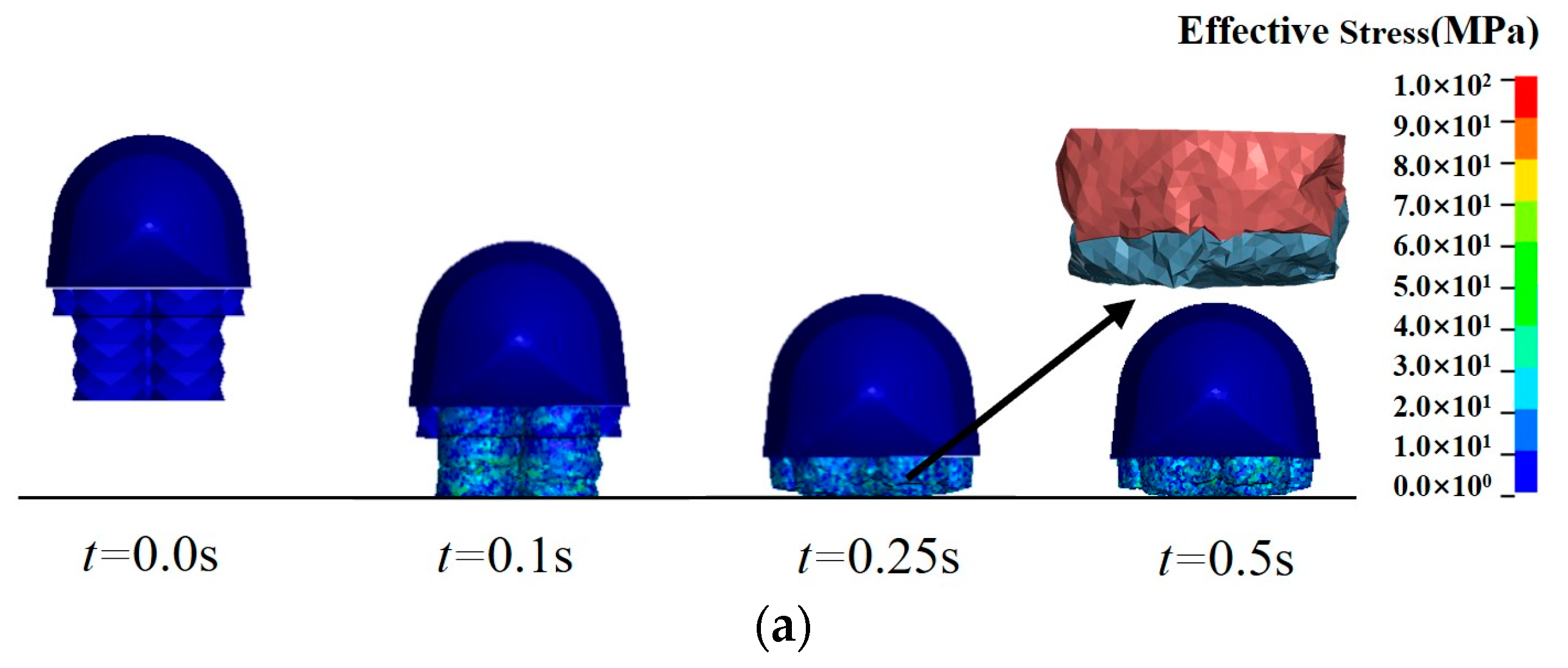
3.3. Analysis Results

For finite element analyses, the number of FEA elements often affects the analysis results. It is necessary to balance the calculation accuracy and cost, so the grid independence analysis is conducted. Three FEA models with the element numbers for the airbags set as 27,960, 60,986, and 101,680 are analyzed (via Intel (R) Core (TM) i5-7300HQ quad-core computing resources), respectively. The maximum overload, pressure peak and calculation cost of the three FEA models are obtained, as shown in Table 2. As can be seen from the results, different FEA element numbers have little influence on the maximum overload and pressure peak. Therefore, the finite element model with an element number of 27,960 is selected for the following analyses.
By simulating the landing attenuation process, the stress contours and the configuration of the origami-inspired cushion airbags are obtained, as shown in Figure 3. It can be seen that the cushion airbags compress and bear a high stress level when they make contact with the ground. The internal pressure of the sealed airbags and the vented airbags increases, and the shape of the cushion airbags becomes a cylindrical shape with creases. There is crumpling of the individual faces of the origami pattern when the internal pressure of the airbags increases, and the airbags are axially compressed. When the internal pressure of the vented airbags exceeds the venting threshold pressure Pe, the exhaust process starts. Thus, the internal pressure of the sealed airbags retains a high value. As the deformation continues, the vented airbags compress along the creases between layers until they are completely folded. The sealed airbags keep the shape, protecting the returnable spacecraft from collision with the ground directly. Due to the presence of the sealed airbags, the returnable spacecraft rebounds slightly at 0.3 s. Under the influence of gravity, the returnable spacecraft falls again until it comes to a rest state at 0.5 s. The forward tilt of the returnable spacecraft’s head is attributed to a non-uniform mass distribution, yet this issue is effectively mitigated by the implementation of cushion airbags. Based on the stress contours of the cushion airbags, the maximum stress strength criterion is utilized to evaluate the strength of the cushion airbags, indicating that the cushion airbag meets the design strength requirement and the material does not undergo any plastic deformation.
To evaluate the cushioning performance, two key indicators are employed here: maximum overload and specific energy absorption (SEA) during the landing attenuation process [23]. The expression of SEA is
S E A = 1 2 M v 1 2 v 2 2 m
where M is the mass of the returnable spacecraft, which is taken as 300 kg in this paper. m is the mass of the cushion airbag system, which is 2.8 kg. v 1 is the velocity before the returnable spacecraft touches the ground, while v 2 is the first peak velocity of the rebound after the returnable spacecraft touches the ground.
The impact overload and the velocity along the Z direction are drawn in Figure 4a,b. It can be seen that the maximum overload during the landing attenuation process is 7.30 g, which is less than the limit value of 10 g that the human body can withstand. Through a calculation using Equation (10), the SEA of the cushion airbags is 1648 J/kg. The results, illustrated in Figure 4c–e for gas state parameters of the cushion airbag and Figure 4f for the kinetic energy of the spacecraft, indicate stable responses of the system after an initial period, with slight fluctuations in impact overload and velocity along the Z direction at 0.5 s. This indicates that the airbag system reaches a point of equilibrium relatively quickly. The dashed lines in all figures are the reference grid lines, and the corresponding y-axis values are marked below the lines. The dashed lines in the following figure are the same as one in this figure. The comparison between traditional cylindrical airbags and origami-inspired airbags, detailed in Supporting Information Note S2, highlights the cushioning performance of origami-inspired airbags.

4. Analyses for Complex Landing Environments

The practical landing environments are much more complex than those in Model A. Not only the landing surface slope but also the landing velocity in different directions of the returnable spacecraft need to be considered.

4.1. Anti-Rollover Design

First, there may be a rollover problem for the cushion airbag system due to the effects of the landing velocity, nonhorizontal landing surface, and so on. To avoid the rollover problem, two anti-rollover supplementary airbags (yellow ones) are set on both sides of the aforementioned combined cushion airbag system to form Model B in Figure 5, which has the same sealed airbags (brown ones) and vented airbags (blue ones) as those used in Model A.

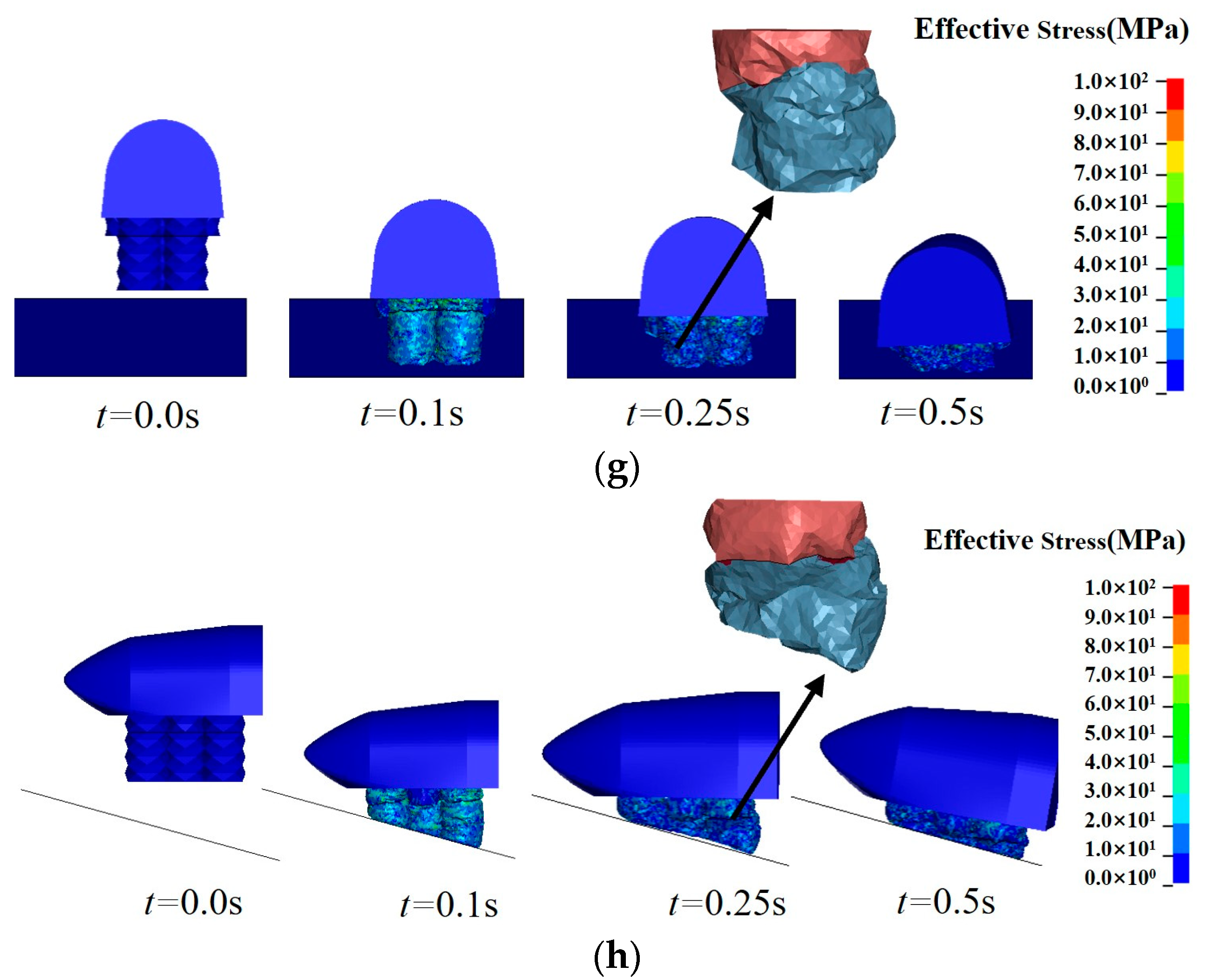
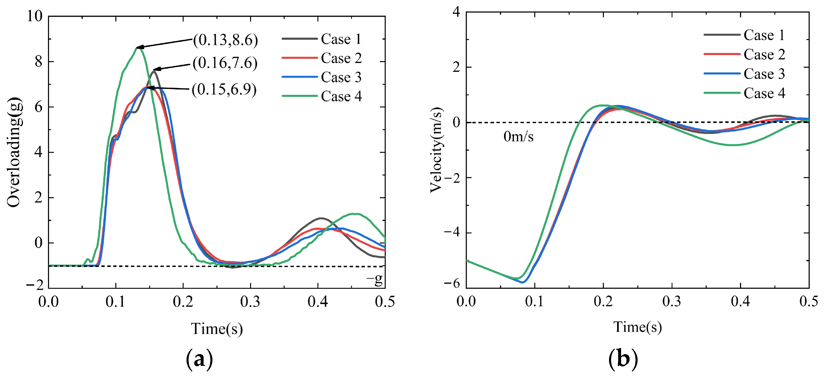
4.2. Analysis Cases for Complex Environments

To evaluate the feasibility of Model B in complex landing environments, different horizontal velocities, lateral velocities and the angle of the nonhorizontal landing surface are combined into four cases, as listed in Table 3.
The finite element analyses for these four cases are conducted in the software LS-DYNA R12.0.0. The stress contours and the configuration of the cushion airbags for the four cases are shown in Figure 6. In the key time t = 0.25 s, the deformation patterns of the connection between the sealed airbag and the vented airbag are zoomed in specifically before the vented airbag completely exhausts at t = 0.5 s.
Evidently, when the airbags are not touching the ground, the stress of the combined airbags are mainly caused by inflation. When the airbags touch the ground, the largest value of the stress is mainly located at the contact position of the airbags. Under the influence of horizontal and lateral velocities, certain degree tipping problems of the returnable spacecraft also exist in the landing attenuation process. However, these cushion airbags work successfully to avoid the spacecraft from collision with the ground directly in these four cases. Even in Case 4, the returnable spacecraft experiences some slippage and then lands smoothly.
The impact overload and the velocity along the Z direction for the four cases are drawn in Figure 7a,b. Specifically, Case 4, with a landing pitch angle of 15° shown as the green line in Figure 7, has a larger overloading peak and larger velocity variation amplitude than those of the other three cases. In various complex landing environments, the overloads of the cushion airbags are less than 10 g. Compared with the results of Model A in Figure 4, Cases 1, 2 and 3 of Model B with different combinations of horizontal and lateral velocities have almost the same curves of impact overload and velocity along the Z direction. It is indicated that the design of anti-rollover supplementary airbags can effectively promote the adaptation of the combined cushion airbag to the complex landing environment.
In addition, the feasibility of Model B in a complex landing surface scenario is evaluated in Supporting Information Note S3. The results show that the system with anti-rollover supplementary airbags can also brilliantly adapt to two types of ground obstacles.

5. Multi-Objective Optimization

5.1. Selection of Optimization Variables

To perform multi-objective optimization, the design parameters that have a great influence on the cushioning performance of the airbags for Model A should be selected. Thus, four design parameters (i.e., initial pressure, venting threshold pressure, vent orifice area and polygon edge number) are selected from Table 4 using the variable-controlling approach. Cases 5, 6, 7, 8, and 9 are taken for the effect of the exhaust vent area A o u t on the cushioning performance. Similarly, Cases 6, 10, 11, and 12 are taken for the effect of the venting threshold pressure Pe. Cases 12, 13, 14, and 15 are taken for the effect of the initial pressure P0, while Cases 11, 16, 17, and 18 are taken for the effect of the polygon edge number L. In Case 18, the polygon edge number L = ∞ indicates that the airbag is a traditional cylindrical airbag.
From the comparison of the results in Table 4 by each single variable, it is evidently shown that the maximum overload is positively correlated with the polygon edge number L. The more polygon edges there are, the more the airbag tends to be a traditional cylindrical airbag, resulting in a maximum overload of 8.6 g for cylindrical cushion airbags (Case 18). It is proven that the origami-inspired cushion airbags have a better cushioning performance compared to traditional cylindrical airbags. The cushion airbag with L = 6 has a better cushioning performance, while the cushioning performance of cushion airbags with L = 8 and L = 10 is close to that of the cylindrical cushion bag. So, the cushion airbag with L = 6 is optimized and selected. The other three design parameters do not have a direct linear correlation with the indicators of the maximum overload value, maximum rebound velocity, and SEA.

5.2. Multi-Objective Optimization Model

Therefore, exhaust vent area A o u t , initial pressure P0, and venting threshold pressure Pe are selected as the optimization variables for the following multi-objective optimization model.
The key indicators for the cushioning performance of the cushion airbags are the maximum overload and SEA. The maximum overload is related to the security of the devices or samples inside the returnable spacecraft. At the same time, SEA of the cushion airbags should be as large as possible to ensure that the rebound velocity of the returnable spacecraft is small. Therefore, the optimization objectives of the combined cushion airbags are
min a max A o u t , P 0 , P e max S E A A o u t , P 0 , P e
Through the influence analyses of the design parameters above, it can be seen that due to the increase in internal pressure during the landing attenuation process, the venting threshold pressure Pe needs to be higher than the initial pressure P0. In summary, the optimization variables and constraints are written as follows:
s . t . 0.003   m 2 A o u t 0.007   m 2 101   kPa P 0 130   kPa 101   kPa P e 190   kPa P 0 P e

5.3. Optimization Design Method

Optimal Latin hypercube sampling is used to sample within the solution domain in a three-dimensional design space [7]. Generally, the number of sample points is 10–20 times more than the number of optimization parameters, which meets the solving requirements of the surrogate model. Thus, 36 sample points in the space are selected as the set to train the surrogate model. Figure 8 is a schematic diagram of the selected sample points in the three-dimensional design space.
Finite element analyses are conducted for the 36 sample points. Then, the maximum overload and SEA of the cushioning airbags corresponding to each sample point are calculated to obtain the optimization objective functions. Due to the fact that neural networks can more effectively approximate complex nonlinear physical problems, the surrogate model is established by a three layers neural network to predict the mapping relationship between the design variables and optimization objectives of the cushion airbags. The node number of the input layer of the established neural network is three, that of the hidden layer is seven, and that of the output layer is two. Then, 36 sample points are used to train the established neural network. The sigmoid function is chosen as the activation function during the neural network training.
To ensure the effectiveness of the surrogate model, it is necessary to verify the accuracy of the established neural network. Another five finite element models are analyzed as the test set. The maximum overload and the SEA obtained via finite element analyses and the surrogate model are compared in Figure 9 to evaluate the accuracy of the neural network. It is illustrated that the deviation between the analysis value and the predicted value is relatively small. The maximum relative errors of the maximum overload value and the SEA are 4.6% and 0.5%, respectively.
Then, the multi-objective water circulation algorithm is applied to optimize the combined cushion airbags [24]. The Pareto front for the cushion airbags is obtained, as shown in Figure 10. We considered the upper limit of the maximum overload of 10 g for human beings and the lower limit of the SEA which is 1640 J/kg for the cushion airbags system, and the selected Pareto front solution is indicated by the arrow in Figure 10. The maximum overload is 6.31 g, and the SEA of the cushion airbags is 1645 J/kg at this point. Three optimization variables of this point are as follows: the exhaust vent area A o u t is 5486 mm2, the initial pressure P0 is 116 kPa, and the venting threshold pressure Pe is 172 kPa. To verify the correctness of the optimized results, the design parameters of this point are adopted to conduct finite element analysis. The maximum overload is 6.10 g, and the SEA of the cushion airbags is 1667 J/kg from the analysis results. The relative errors of the maximum overload and the SEA are 3.3% and 1.3%, respectively.
To verify the effectiveness of the optimization design method, the cushioning performance before and after optimization is compared in Figure 11 and Table 5. The design parameters of the model before optimization are chosen from Section 3 (the exhaust vent area A o u t is 4000 mm2, the initial pressure P0 is 101 kPa, and the venting threshold pressure Pe is 130 kPa).
The maximum overload before optimization is 7.30 g, while the value after optimization is 6.10 g, which reduces the value by 16.4%. The SEA before optimization is 1648 J/kg, while the value after optimization is 1667 J/kg, which increases in value by 1.2%. It can be seen that the SEA does not change much before and after optimization. The reason is that the first peak velocity of the rebound process v 2 is a small value compared to the velocity v 1 and the SEA is hard to increase dramatically. Therefore, it is verified that the optimized cushioning airbag system has a better cushioning performance, especially for the maximum overload.

6. Conclusions

This paper develops a novel origami-inspired combined cushion airbag to improve the cushioning performance of soft-landing systems. The maximum overload of the origami-inspired airbag is 7.30 g. The specific energy absorption of the origami-inspired airbag is 1648 J/kg, indicating that it has a better cushioning performance compared to traditional cylindrical airbags. Via the anti-rollover design, the returnable spacecraft with the origami-inspired combined cushioning airbag system can avoid the problems of tipping and sinking. The cushion airbags also have a good cushioning performance in complex landing environments, considering the influence of horizontal velocity, lateral velocity, and the nonhorizontal landing surface.
Through the influence analyses of the design parameters, it can be seen that the origami-inspired cushion airbags with polygon edge number L = 6 have a better cushioning performance compared to traditional cylindrical airbags. Three design parameters, including the exhaust vent area A o u t , the initial pressure P0, and the venting threshold pressure Pe, are selected as the optimization variables. A multi-objective optimization model of the cushion airbags is established by combining the surrogate model and the water cycle optimization algorithm to obtain the final optimization design scheme. After the optimization design, the maximum overload of the cushion airbags is reduced by 16.4% and the SEA is increased by 1.2%. The effectiveness of this multi-objective optimization design method is verified. In the optimization model for the combined cushion airbags, the maximum overload and SEA are selected as optimization objectives, with a focus on optimizing cushioning performance from a technological standpoint without considering economic costs. However, altering these variables to achieve the optimization goals does not necessarily complicate the system or increase economic costs, implying that significant performance gains can be achieved through clever design without additional complexity or expense. Origami-inspired combined cushion airbags, with their complex patterns and potentially greater surface area, offer superior cushioning and energy absorption capabilities. However, their complex design increases manufacturing difficulty. This complexity can lead to higher production costs, making them less cost-effective compared to simpler cylindrical designs.
This study provides technical support for the soft-landing system design of returnable spacecrafts, but it is mainly limited to numerical simulations. An experimental verification will be carried out to verify the numerical simulation results, and the feasibility of applying other origami patterns to the cushion airbags will be explored in the future.

Supplementary Materials

The following supporting information can be downloaded at: https://www.mdpi.com/article/10.3390/aerospace11030169/s1, Figure S1: Comparison of deformation configurations; Figure S2: Comparison of dynamic response; Figure S3: Model for traditional cylindrical airbags; Figure S4: Dynamic response curves of two types of airbags; Figure S5: Model B with considering ground obstacles in two cases; Figure S6: Stress contours of Model B with considering ground obstacles in two cases.

Author Contributions

Conceptualization, Y.X.; methodology, H.H.; software, Y.Y.; validation, Y.X.; formal analysis, Y.Y.; investigation, G.C.; resources, G.L.; data curation, H.C.; writing—original draft preparation, Y.Y., G.L. and H.C.; writing—review and editing, Y.X., H.H. and G.C.; visualization, H.C.; supervision, Y.X.; project administration, G.C. and G.L.; funding acquisition, Y.X. and H.H. All authors have read and agreed to the published version of the manuscript.

Funding

This research was funded by the National Natural Science Foundation of China (Grant No. 91748209, 11402229 and 11902253), the Shanghai Aerospace Science and Technology Innovation Fund (Grant No. SAST2021-059) and the Fundamental Research Funds for the Central Universities of China (310201906zy008).

Data Availability Statement

Data are contained within the article.

Conflicts of Interest

The authors declare no conflicts of interest.

References

  1. Zhou, X.; Zhou, S.; Li, D.; Cui, D.; Dong, C. Research on design and cushioning performance of combined lunar landing airbag. Acta Astronaut. 2022, 191, 55–78. [Google Scholar] [CrossRef]
  2. Wang, H.Y.; Hong, H.J.; Hao, G.X.; Deng, H.; Rui, Q.; Li, J. Characteristic verification and parameter optimization of airbag cushion system for airborne vehicle. Chin. J. Mech. Eng. 2015, 27, 50–57. [Google Scholar] [CrossRef]
  3. Tutt, B.; Sandy, C.; Corliss, J. Status of the development of an airbag landing system for the Orion Crew Module. In Proceedings of the 20th AIAA Aerodynamic Decelerator Systems Technology Conference and Seminar, Seattle, WA, USA, 4–7 May 2009; pp. 1–13. [Google Scholar]
  4. Timmers, R.; Hardy, R.; Welch, J. Modeling and simulation of the second-generation Orion Crew Module airbag landing system. In Proceedings of the AIAA SPACE 2009 Conference & Exposition, Pasadena, CA, USA, 14–17 September 2009; pp. 1–14. [Google Scholar]
  5. Slade, R.; Sharp, P.; Jones, R.; Toropov, V. Analysis, optimization and probabilistic assessment of an airbag landing system for the ExoMars space mission. In Proceedings of the 11th AIAA/ISSMO Multidisciplinary Analysis and Optimization Conference, Portsmouth, VA, USA, 6–8 September 2006; pp. 1–9. [Google Scholar]
  6. Wang, J.T.; Nefske, D.J. A New CAL3D Airbag Inflation Model; SAE Transactions; SAE: Warrendale, PA, USA, 1988; pp. 697–706. [Google Scholar]
  7. He, H.; Chen, Z.; He, C.; Ni, L.; Chen, G. A hierarchical updating method for finite element model of airbag buffer system under landing impact. Chin. J. Aeronaut. 2015, 28, 1629–1639. [Google Scholar] [CrossRef]
  8. Wang, H.Y.; Hong, H.J.; Li, J.Y.; Rui, Q. Study on multi-objective optimization of airbag landing attenuation system for heavy airdrop. Def. Technol. 2013, 9, 237–241. [Google Scholar] [CrossRef]
  9. Zhou, X.; Zhou, S.; Li, D.; Zhou, A. Direct folding method of cylindrical airbag and its application in landing buffer. J. Aerosp. Eng. 2022, 35, 04022083. [Google Scholar] [CrossRef]
  10. Dmitri, F.; Nitin, L.; Lars, F. On airbag simulation in LS-DYNA with the use of the arbitrary Lagrangian-Eulerian method. In Proceedings of the 4th European LS-DYNA Users Conference, Ulm, Germany, 22–23 May 2003. [Google Scholar]
  11. Ma, J.; Chai, S.; Chen, Y. Geometric design, deformation mode, and energy absorption of patterned thin-walled structures. Mech. Mater. 2022, 168, 104269. [Google Scholar] [CrossRef]
  12. Gattas, J.M.; Lv, W.; Chen, Y. Rigid-foldable tubular arches. Eng. Struct. 2017, 145, 246–253. [Google Scholar] [CrossRef]
  13. Garrett, D.; You, Z.; Gattas, J.M. Curved crease tube structures as an energy absorbing crash box. In Proceedings of the International Design Engineering Technical Conferences and Computers and Information in Engineering Conference, Charlotte, NC, USA, 21–24 August 2016; p. 50169. [Google Scholar]
  14. Xiang, X.M.; Lu, G.; You, Z. Energy absorption of origami inspired structures and materials. Thin-Walled Struct. 2020, 157, 107130. [Google Scholar] [CrossRef]
  15. Liu, X.; Li, D.H. Analysis of diamond-patterned origami tubes under axial crushing forces. Appl. Math. Mech. 2017, 38, 163–169. [Google Scholar]
  16. Yuan, L.; Shi, H.; Ma, J.; You, Z. Quasi-static impact of origami crash boxes with various profiles. Thin-Walled Struct. 2019, 141, 435–446. [Google Scholar] [CrossRef]
  17. Yang, K.; Xu, S.; Zhou, S.; Xie, Y.M. Multi-objective optimization of multi-cell tubes with origami patterns for energy absorption. Thin-Walled Struct. 2018, 123, 100–113. [Google Scholar] [CrossRef]
  18. Faraj, R.; Popławski, B.; Gabryel, D.; Kowalski, T.; Hinc, K. Adaptive airbag system for increased evacuation safety. Eng. Struct. 2022, 270, 114853. [Google Scholar] [CrossRef]
  19. Wu, Q.; Yu, L.; Yao, X.R. Study on the cushioning properties of airbag and the effect of vent size. Comput. Simul. 2016, 33, 85–89. [Google Scholar]
  20. Zhang, X.; Chen, Y. The diamond thick-panel origami and the corresponding mobile assemblies of plane-symmetric bricard linkages. Mech. Mach. Theory 2018, 130, 585–604. [Google Scholar] [CrossRef]
  21. Willey, C.; Sandy, C.; Welch, J.; Timmers, R. Impact attenuating airbags for earth and planetary landing systems. In Proceedings of the AIAA SPACE 2007 Conference & Exposition, Long Beach, CA, USA, 18–20 September 2007; p. 6172. [Google Scholar]
  22. Gao, H.H.; Wang, H.H.; Zhang, H.Y.; Tong, M.B. Experimental Research on Buffer Performance of Recycling Airbag for a Drone. Spacecr. Recovery Remote Sens. 2021, 42, 30–38. (In Chinese) [Google Scholar]
  23. Zhang, P.F.; Wei, J.Z.; Chen, X.Y.; Tan, H.F.; Zhu, M.F. Analysis and multi-objective optimization for buffer performance of heavy landing airbags. J. Vib. Shock 2020, 39, 91–98,142. (In Chinese) [Google Scholar]
  24. Sadollaha, A.; Eskandarb, H.; Kim, J.H. Water cycle algorithm for solving constrained multi-objective optimization problems. Appl. Soft Comput. 2015, 27, 279–298. [Google Scholar] [CrossRef]
Figure 1. Layouts of the combined cushioning airbag system. (a) Returnable spacecraft configuration. (b) Combined cushion airbag. (c) Front–back view of the airbag system. (d) Top–down view of the airbag system.
Aerospace 11 00169 g001
Figure 2. Schematic diagram of tensile test sample and test process. (a) Material design of cushion airbag. (b) Test piece model. (c) Stress–strain curve.
Aerospace 11 00169 g002
Figure 3. Stress contours of Model A during the landing attenuation process.
Aerospace 11 00169 g003
Figure 4. Dynamic response curves of Model A. (a) Impact overload. (b) Velocity along Z direction. (c) Pressure of the vented airbag. (d) Volume of the vented airbag. (e) Mass of the vented airbag. (f) Kinetic energy of the spacecraft.
Aerospace 11 00169 g004
Figure 5. Model B with anti-rollover supplementary airbags. (a) Front–back view. (b) Top–down view.
Aerospace 11 00169 g005
Figure 6. Stress contours of Model B for four cases. (a) Axial view of Case 1. (b) Lateral view of Case 1. (c) Axial view of Case 2. (d) Lateral view of Case 2. (e) Axial view of Case 3. (f) Lateral view of Case 3. (g) Axial view of Case 4. (h) Lateral view of Case 4.
Aerospace 11 00169 g006aAerospace 11 00169 g006bAerospace 11 00169 g006c
Figure 7. Dynamic response curves of Model B in four cases. (a) Impact overload. (b) Velocity along Z direction.
Aerospace 11 00169 g007
Figure 8. Optimal Latin hypercube design.
Aerospace 11 00169 g008
Figure 9. Comparison of true and predicted values. (a) Comparison of maximum overload. (b) Comparison of SEA.
Aerospace 11 00169 g009
Figure 10. Pareto front for the cushioning airbag system.
Aerospace 11 00169 g010
Figure 11. Curves comparison before and after optimization. (a) impact overload. (b) velocity along Z direction.
Aerospace 11 00169 g011
Table 1. Material parameters of returnable spacecraft and cushion airbags.
Elastic Modulus (MPa)Poisson RatioDensity (kg/m3)
Cushion airbag9.3 × 1020.351.60 × 103
Returnable spacecraft3.0 × 1050.301.25 × 104
Ground3.0 × 1050.307.80 × 103
Table 2. Grid independence analysis.
Number of FEA Elements27,96060,986101,680
Peak overload (g)7.257.057.08
Pressure peak (KPa)153161157
Calculation cost (minute)3268115
Table 3. Typical cases for complex landing environments.
Descending Velocity (m/s)Horizontal Velocity (m/s)Lateral Velocity (m/s)Landing Pitch
Angle (°)
Case 1−5200
Case 2−5020
Case 3−5220
Case 4−50015
Table 4. Typical cases of different parameter combinations and results of key indicators.
Case Exhaust   Vent   Area   A o u t (mm2)Initial Pressure P0 (kPa)Venting Threshold Pressure Pe (kPa)Polygon Edge Number LMaximum Overload Value amax (g)Maximum Rebound Velocity v2 (m/s)Specific Energy Absorption SEA (J/kg)
5300010113067.50.961637
6400010113067.30.771655
7500010113066.50.691661
8600010113068.71.291598
97000101130611.91.771521
10400010110168.20.811651
11400010116067.30.441676
12400010119069.20.671663
13400013019067.40.221683
14400016019066.20.511672
15400019019066.10.611666
16400010116088.40.451675
174000101160108.40.521672
1840001011608.60.461675
Table 5. Comparison before and after optimization.
Exhaust Vent Area (mm2)Initial Pressure (kPa)Venting Threshold Pressure (kPa)Maximum Overload (g)SEA (J/kg)
Before optimization40001011307.31648
After optimization54861161726.11667
Disclaimer/Publisher’s Note: The statements, opinions and data contained in all publications are solely those of the individual author(s) and contributor(s) and not of MDPI and/or the editor(s). MDPI and/or the editor(s) disclaim responsibility for any injury to people or property resulting from any ideas, methods, instructions or products referred to in the content.

