Article

Determination of Jupiter’s Pole Orientation from Juno Radio Science Data

1
Dipartimento di Matematica, Università di Pisa, Largo Bruno Pontecorvo 5, 56127 Pisa, Italy
2
Dipartimento di Ingegneria Industriale, Università di Bologna, Via Fontanelle 40, 47121 Forlì, Italy
3
Dipartimento di Ingegneria Meccanica e Aerospaziale, Università La Sapienza di Roma, Via Eudossiana 18, 00138 Roma, Italy
4
Jet Propulsion Laboratory, California Institute of Technology, 4800 Oak Grove Dr, Pasadena, CA 91109, USA
*
Author to whom correspondence should be addressed.
Aerospace 2024, 11(2), 124; https://doi.org/10.3390/aerospace11020124
Submission received: 8 December 2023 / Revised: 27 January 2024 / Accepted: 30 January 2024 / Published: 31 January 2024

Abstract

:
The extreme accuracy of Juno radio science data allows us to perform very precise orbit determination experiments. While previous works focused on the estimation of the gravitational field of Jupiter, in this article, we aim to accurately determine the planet’s orientation in space. For this purpose, we implement a rotational model of Jupiter, taking into account also its main deformations, as they affect the planet’s inertia components. Rotation parameters are estimated simultaneously with all other parameters (especially gravity and tides), in order to obtain a global and coherent solution. In our experiments, we find that Juno data manage to constrain Jupiter’s pole direction with an accuracy of around 10 7 radians for the whole duration of the mission, allowing us to improve its long-term ephemerides. Moreover, Juno data provide an upper bound on the maximum displacement between Jupiter’s pole and spin axis of less than 10 m, which allows us to investigate possible short-period nutation effects due to, for example, atmospheric and interior processes of the planet.

1. Introduction

NASA’s Juno space mission has been orbiting around Jupiter since 2016 [1], disclosing the mysteries concealed under the tumultuous clouds of the planet. The spacecraft moves on a highly elliptic orbit with a period of about 50 days, so that it is close to the planet only for a few hours during the perijoves (PJs) of its orbit. During these short time intervals, the radio science experiment of Juno collects extremely accurate Doppler data [2] that are processed to precisely estimate the gravitational field of the planet [3,4]. Using Jupiter’s gravity field as a constraint, it was possible to greatly improve the models of the interior and the winds of the planet [5,6,7,8,9].
Although the nominal end of the mission was planned for perijove number 34 (PJ34), which occurred in June 2021, NASA extended Juno’s scientific operations for another 4 years, moving the end of the mission to September 2025. With the mission extension, Juno spacecraft will arrive at a total of 76 close encounters with Jupiter, before probably entering its atmosphere and crashing into the planet, like Cassini with Saturn. In between the perijoves, during the extended mission, a few flybys of the Galilean moons have been scheduled, providing the possibility to closely observe Jupiter’s moons [10,11] before the arrival of NASA’s mission Europa Clipper [12] and ESA’s mission JUICE [13].
Figure 1. Evolution of Jupiter’s pole direction (described by right ascension α and declination δ ) in the International Celestial Reference Frame (ICRF) from 1900 to 2100, as obtained from the kinematic model of the last IAU report [14]. In red, we highlighted the evolution path during the time covered by the Juno mission (from 2016 to 2025). The asterisks indicate the pole position every 10 years starting from 1900 and the arrows the direction of the motion.
Aerospace 11 00124 g001
While the primary objective of the radio science experiment was to provide a global estimation of the gravity field of Jupiter, the collection of a large, though sparse, set of data allowed us to investigate different features of Jupiter’s dynamical environment. Indeed, just after the first few perijoves, it was possible to obtain a precise measurement of the planet’s zonal (or axially symmetric) gravity field, revealing also its asymmetry with respect to the equator [3,15], linked to the presence of deep zonal flows [7]. The addition of new data revealed the deviation of Jupiter’s tidal response from the expected equilibrium tides and also hints of a small non-zonal or time-variable gravity signal [4]. Further analyses obtained an estimation of the depth of Jupiter’s great red spot [16] and found that normal modes within the planet are the probable source of the unexplained gravity signal present in the Doppler data [17].
Juno radio science data can also be used to constrain the orientation of the planet [4,18,19]. Their sensitivity to Jupiter’s orientation in space is related to its gravity signal. Indeed, the static gravity field of Jupiter is defined in a body-fixed reference frame, which rotates in the inertial frame where the translational motion of the bodies is studied (e.g., mean equatorial or ecliptic J2000 frames). Because of the almost totally zonal nature of the gravitational field, radio science data are very sensitive to the pole orientation, while they are insensitive to the intrinsic rotation of Jupiter. Therefore, in this article, we want to study the rotational dynamics of Jupiter and provide an accurate estimation of Jupiter’s pole orientation during the time of the mission, as obtained from radio science data.
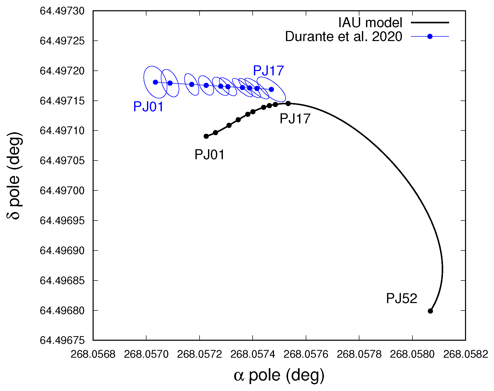
Long-term ephemerides for Jupiter’s orientation have been already obtained using data from previous space missions (e.g., Voyager and Galileo) and are usually provided in the form of trigonometric series, like in International Astronomical Union (IAU) reports [14] (see Figure 1). The precise knowledge of current Jupiter’s state and dynamical properties is essential to reconstruct its evolution on a billion-year timescale [20,21,22]. In this context, the Juno space mission is collecting further observations useful to reconstruct Jupiter’s motion. Indeed, fitting Juno data up to PJ17 and using an approximated linear model, Durante et al. [4] determined Jupiter’s pole direction with a 3- σ uncertainty of about 10 6 radians within the time interval of the mission (see Figure 2), which is a large improvement with respect to previous estimations ([23]; about 10 5 radians, 1- σ uncertainty). Therefore, the extreme accuracy of Juno data allows us to precisely constrain the short-period motion of its pole and to improve the description of its long-term evolution. While the latter has been already implemented in the new Jet Propulsion Laboratory (JPL) ephemerides of the Jovian system (https://naif.jpl.nasa.gov/pub/naif/JUNO/kernels/spk/jup380s.bsp.lbl, last accessed on 27 January 2024), we still do not have a direct estimation of a possible displacement between the direction of the pole and the spin axis of Jupiter, which could result in a short-period nutation of the planet’s pole (see, e.g., [24]).

2. Methods

2.1. Orbit Determination

Thanks to the Ka-band transponder provided by the Italian Space Agency onboard the spacecraft, X and Ka-band radio signals transmitted by ground-based stations are received by Juno and sent back to Earth, providing very precise radio science data. In particular, there are two kinds of observables that are collected: range and Doppler (or range-rate). Range data are a measure of the distance ρ covered by the light-time travel of the radio signal, while Doppler data measure the change in frequency of the signal from transmission to reception. Indeed, the variation in the range ρ ˙ (range-rate), due to the spacecraft’s large speed and to the dynamical effects that it undergoes, is reflected in a Doppler effect in the final received signal.
In our analysis, we consider only Doppler data collected by Juno at the various PJs, as the contribution of range data for our experiment is negligible. Therefore, Doppler data form our entire set of observed data O i ( i = 1 , m ), each taken at a corresponding receiving time t i . Since the result of the observations depends on various parameters and on the states (positions and velocities) of the involved natural or artificial bodies (Earth, ground-based antenna, Jupiter and spacecraft), we must use precise observation models and propagate dynamical models of these bodies in order to predict the observation values. In this way, at the corresponding times, we obtain the computed observables C i ( x ) , which depend on a list of dynamical and kinematic parameters x j ( j = 1 , N ) . The goal of the orbit determination process is to find the values of the fit parameters x that minimize the residuals ξ i = O i C i [25]. More precisely, we want to minimize the target function
Q ( x ) = 1 m ξ T W ξ ,
where W = diag ( ( σ i ) 2 ) ( i = 1 , m ) is the weight matrix of the observables, whose elements are the inverse square of the accuracy σ i of the single data. In terms of two-way radial velocity, the nominal accuracy of Doppler data obtained from the Ka-band transponder is 3 × 10 4 cm/s at an integration time of 1000 s. For our data set, we compressed the observations to 60 s and we empirically evaluated an average accuracy for each PJ (see, e.g., [4,26]).
In order to find the minimum of the target function (1), i.e., to solve the equation Q / x = 0 , we use an iterative procedure called differential corrections, which is an approximation of the classic Newton method (for details see [25]):
C ( x k + 1 x k ) = D ,
where C = B T W B is called normal matrix, D = B T ξ is the constant term of the equation and B = ξ / x is called design matrix (all evaluated at x k ). From these formulas, we can note that apart from propagating the states y ( t ) of the involved bodies for computing ξ , it is necessary also to propagate their partial derivatives with respect to the fit parameters y ( t ) / x for computing B. At the convergence of the differential corrections, we obtain a nominal solution x of the fit parameters, whose formal uncertainties and correlations can be retrieved in the covariance matrix Γ = C 1 .
For some parameters, it is possible to have a preliminary knowledge of their value x P , which can help to better determine them. This a priori information can come both from previous estimations with other data sets or theoretical considerations. The a priori contribution can be added to the orbit determination process as N further observations. We define an N × N a priori normal matrix
C P = diag ( ( σ j P ) 2 ) ,
where σ j P ( j = 1 , N ) is the uncertainty with which the parameters are considered already known (if for one parameter x j no knowledge is available, we can set σ j P = ). Then we add to the target function (1) a new piece that we require to minimize
Q P ( x ) = 1 N ( x x P ) T C P ( x x P ) ,
so that the complete normal matrix becomes C = C P + B T W B .
In the end, the orbit determination will provide for each fit parameter x j an estimation of the form x j = x j ± 3 ς j , where x j is the nominal solution obtained at convergence of the differential corrections and ς j is the corresponding formal uncertainty computed from the covariance matrix. We include a factor 3 in order to consider more conservative 3- σ uncertainties instead of 1- σ , assuming that the probability distribution of the errors is represented by a Gaussian.
For a detailed description of the observation model for computing Doppler data we refer to previous works [26,27,28]. All the analysis presented in this paper was carried out using the Orbit14 software, an orbit determination software developed at the University of Pisa [28].

2.2. Spacecraft’s Dynamics

The orbit of Juno around Jupiter is affected by different kinds of perturbations. As radio science data are very accurate, we need to take into account also tiny dynamical effects in order to fit properly the observations. The main contribution to the spacecraft’s acceleration is due to the static gravitational field of the planet, whose potential can be expressed as
U J ( r ) = G M J r + G M J r = 2 max R J r m = 0 P m ( sin ϑ ) C m cos ( m ϕ ) + S m sin ( m ϕ ) ,
where G M J is the gravitational parameter of Jupiter and R J its equatorial radius, P m are the Legendre associated functions of degree and order m, and ( r , ϑ , ϕ ) is the representation in spherical coordinates (distance, latitude, longitude) of the position of the spacecraft r in a body-fixed reference frame of Jupiter. Because of the nature of the planet, Jupiter’s static gravity field is almost axially symmetric, so we can describe it by means of zonal parameters J = C 0 only. However, in our model, we consider also the gravitational effect due to the tesseral quadrupole coefficients C 21 , S 21 , C 22 and S 22 , as they can affect the rotation of Jupiter (see next section). For Jupiter, their values are expected to be zero and their maximum values have been bounded by Juno (≲ 10 9 , see [4,28]). All the other static tesseral coefficients ( m 0 ) are fixed to zero.
Apart from static features, there are contributions to the gravity field of Jupiter that vary with time. Indeed, the tidal perturbation due to the Galilean moons raises significant bulges on the planet, which modify the planet’s gravitational field. We can take into account these effects considering a variation in the gravitational parameters given by the following formulas:
Δ C m t Δ S m t = k m 2 + 1 i = 1 4 m i M J R J r i + 1 P m ( sin ϑ i ) cos ( m ϕ i ) sin ( m ϕ i )
where k m is the tidal parameter of degree and order m, m i are the masses of the satellites and ( r i , ϑ i , ϕ i ) are their spherical coordinates ( i = 1 , 4 ). For Jupiter, only tidal parameters with degree and order both even or both odd are expected to be significantly different from zero [29].
Recently, Durante et al. [17] proposed normal modes within Jupiter as the source of the small signals detected by Juno radio science data [4]. Normal modes are interior oscillations of the planet that make its internal masses shift, perturbing the gravity field. Their effect can be included in the dynamical model as periodic variations in the spherical harmonic coefficients [17]:
Δ C m n = n C ˜ m n cos ( ω m n t + ζ m n )
where C ˜ m n , ω m n and ζ m n are the amplitudes, frequencies and phases, respectively. The periods associated with these effects are very short, from some minutes to a few hours.
The accelerations due to Jupiter’s gravity are computed in the body-fixed reference frame of the planet. Then, through a change in coordinates, we can write them in the inertial frame (e.g., ecliptic J2000) where the spacecraft’s motion is propagated. This way, the orientation parameters of Jupiter enter into the dynamics of Juno, as they define the rotation matrix of the coordinate transformation (see next section).
Finally, apart from Jupiter’s gravity, we must consider also the gravitational perturbations of the Sun, other planets and Jovian satellites on the spacecraft. Moreover, relativistic corrections and non-gravitational forces, such as the radiation pressure due to the Sun, are also included in the dynamical model of Juno (see [28] for details).

2.3. Rotational Dynamics of Jupiter

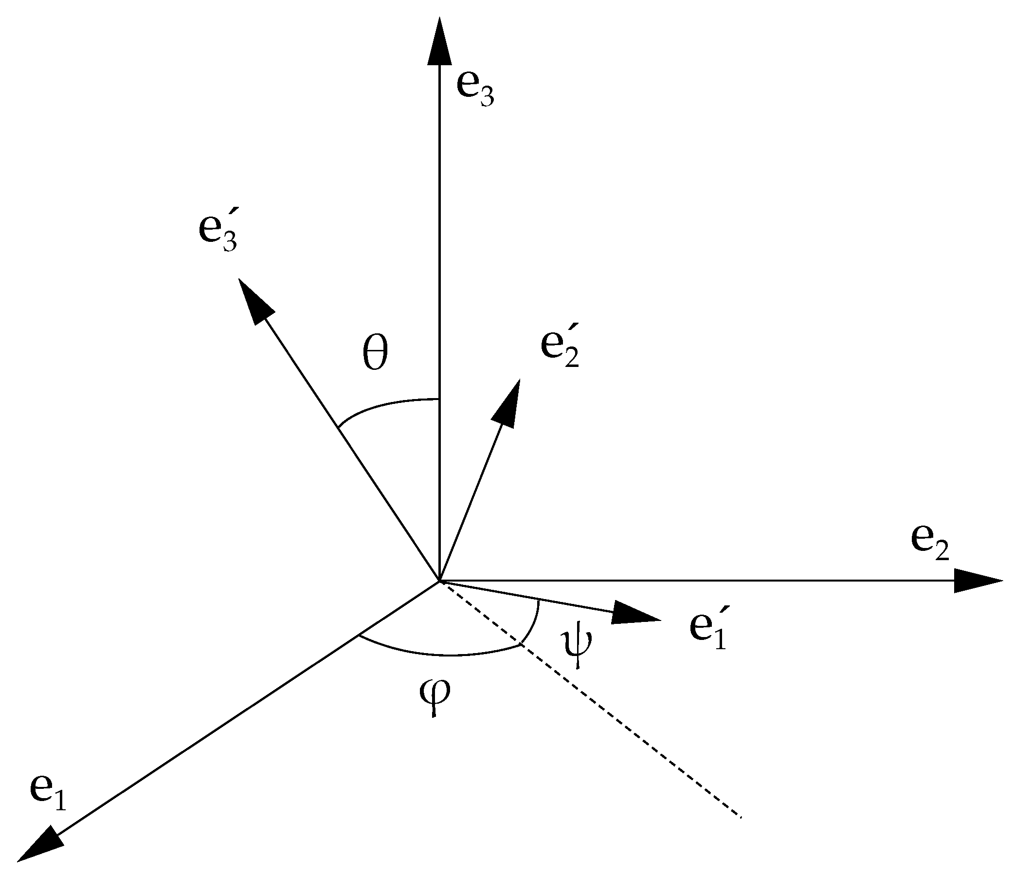
In order to study the orientation of Jupiter, we define a body-fixed reference frame Σ = O e 1 e 2 e 3 centered in the planet’s center of mass. The orientation of Σ with respect to the frame where we study the motion of the spacecraft is identified by the 3-1-3 Euler angles ( φ , θ , ψ ) . The angle φ is called the precession angle, θ is the nutation angle and ψ is the intrinsic rotation angle (see Figure 3).
For a rigid body, the versors e i point at fixed points on its surface; generally e 1 indicates the position of the prime meridian of the planet, e 3 its pole and e 2 = e 3 × e 1 . As Jupiter is a gas giant, we cannot fix e i to special points on the planet’s surface. For this reason, there is not an immediate univocal Σ to study the orientation of Jupiter. For now, therefore, we consider a generic body-fixed reference frame, where e 3 points at (or close to) the pole of Jupiter, which we will define later. From the definition of the Euler angles, we have that the direction of e 3 is given only by the first two angles ( φ , θ ) . They are related to the more commonly used right ascension α and declination δ through the formulas α = φ π / 2 and δ = π / 2 θ [14].
Similarly to previous analyses conducted on gas giants (e.g., [30,31]), for propagating the orientation of Jupiter, we use the following differential equations, written in Σ :
I ω ˙ = N ω × I ω I ˙ ω
where I is the matrix of inertia, ω is the spin vector and N is the sum of the external torques of the Sun and the Galilean satellites acting on the non-spherical gravity field of Jupiter. We consider the torques only on the main harmonics of the planet, i.e., J 2 , J 4 and J 6 . More precisely,
N = i = 0 4 r i × m i r i U J ( r i )
where m i and r i are the masses and position vectors of the external bodies (0 for the Sun and 1 , 2 , 3 , 4 for the Galilean moons), and U J is the gravitational potential of Jupiter computed at the bodies’ positions (see Equation (5)).
Equation (8) is written in terms of the spin vector ω , but using the relations
ω x = φ ˙ cos θ sin ψ + θ ˙ cos ψ , ω y = φ ˙ sin θ cos ψ θ ˙ sin ψ , ω z = ψ ˙ + φ ˙ cos θ ;
we can pass to differential equations for the Euler angles.
In Equation (8), we consider Jupiter’s matrix of inertia composed of a rigid and a variable part I = I rig + I var , in order to take into account the main deformations of the planet (e.g., due to tides). It is worth noting that, even though Jupiter is a gas giant, I rig I var ; therefore, the term I ˙ ω = I ˙ var ω is generally small, even though it is not always negligible (see Section 4.2). The rigid part of the matrix of inertia can be expressed as
I rig = M J R J 2 λ J 2 C 22 2 S 22 C 21 2 S 22 λ J 2 + C 22 S 21 C 21 S 21 λ ,
where λ the normalized (with respect to the equatorial radius) polar moment of inertia and the other parameters have been already presented in Section 2.2. The parameter λ has a value of about 0.264 , obtained from constraints on interior models of Jupiter [5,32]. While the gravitational coefficients also appear in the dynamics of the spacecraft, the moment of inertia λ influences directly only the rotational dynamics of Jupiter and then indirectly the orbital motion of Juno. Apart from these dynamical parameters, in order to propagate the orientation of Jupiter we need suitable initial conditions of the Euler angles ( φ 0 , θ 0 , ψ 0 , φ ˙ 0 , θ ˙ 0 , ψ ˙ 0 ) . We take them evaluating the kinematic model presented by Archinal et al. [14]: we choose the initial time near the current middle epoch of the Juno mission (see Table 1).
As already pointed out, the periodic deformations of Jupiter generate a small contribution I var to the matrix of inertia (see [33] for a detailed description in the case of Earth’s Moon). The main effect is due to the tides raised by the Galilean satellites on the planet. Jupiter’s tidal deformation at order 2 is mainly described by the parameter k 22 , which is determined from Juno radio science experiment [4]. As k 22 produces a periodic variation in the parameters C 22 and S 22 (see Equation (6)), its contribution affects only the principal minor of the matrix I, which we include in our dynamical model. We take into account also the contribution of k 20 to J 2 , which is almost completely constant (permanent tide). Moreover, in Section 4.2, we will discuss the effect of Jupiter’s normal modes on the rotational dynamics of the planet, which we neglect in our nominal experiments.
The orientation of the body-fixed reference frame intervenes in the orbit determination as it influences the dynamics of Juno (see Section 2.2). Indeed, Σ is the frame where accelerations due to Jupiter’s gravitational field are computed (see Equation (5)), and then they are expressed in the inertial frame Σ through the rotation defined by
R = R 3 ( ψ ) R 1 ( θ ) R 3 ( φ ) ,
where the values of Euler angles are retrieved from the numerical integration of Equation (8).
Therefore, a change in the parameters in Equation (8) can generate a signal in the observations. These parameters are then added to the list of fit parameters x (see Section 2.4). Actually, not all of them can be constrained by the radio science data. In particular, as the gravity field of Jupiter is almost purely zonal, Juno is almost insensitive to changes in the intrinsic rotation of the planet. For this reason, we will estimate only the four elements of the initial conditions related to the pole ( φ 0 , θ 0 , φ ˙ 0 , θ ˙ 0 ) , while we do not solve for ( ψ 0 , ψ ˙ 0 ) .
Furthermore, if we consider only the main part I rig of the moment of inertia, we can compute the principal axes of inertia of the (rigid) planet. We call the pole of the planet the intersection between the third principal axis and the planet’s ideal surface. If C 21 = S 21 = 0 , then e 3 corresponds to this principal axis and it points toward the pole; therefore, in this case, ( φ , θ ) indicates exactly the position of the pole in space. Without loss of generality, in our nominal experiment, we can set C 21 = S 21 = 0 , so that the estimation of ( φ 0 , θ 0 , φ ˙ 0 , θ ˙ 0 ) corresponds to determine the initial conditions of Jupiter’s principal polar axis. Nevertheless, in Section 3, we investigate and discuss also the case in which we solve for C 21 and S 21 .
Figure 1 shows the evolution of the pole in 200 years as obtained from the IAU model [14]. The same evolution can be obtained by integrating the dynamical model that we implemented in this section, provided that we use the same initial conditions and parameters’ values. In the time interval covered in Figure 1, the total variation in the angles is extremely small, as the precession period of Jupiter is several orders of magnitude greater, around 500 thousand years [20]. In the IAU model, the spin vector of Jupiter is always almost coincident with the pole direction, so that only medium and long-term effects appear in the pole path (order of years or larger). In particular, from Figure 1, we can note the loops in the path of the pole with periods of tens of years, which correspond to nutation motions due to the external torques of the Galilean satellites on Jupiter. On the contrary, a small constant displacement between the two vectors would generate a free short-period nutation of the planet. Our goal is to use Juno radio science data in order to investigate and estimate such possible displacement. While over very large timescales we could expect that such nutation movements should have been damped by dissipative effects (see, e.g., [34]), it is possible that atmospheric or interior processes within a planet let small oscillations of the pole survive (see, e.g., [35]).

2.4. Experiment Setup

The processing of radio science data of an interplanetary mission requires very precise modeling of observations and spacecraft’s dynamics. As a consequence, computed Doppler data depend on a very large number of parameters that affect the dynamics of the spacecraft and of the bodies involved in the observation, in particular Jupiter and Earth. In our experiment, we model and propagate:
On the contrary, we take the states of other bodies that intervene in the dynamics or the observation from external ephemerides:
  • Jupiter, other planets and the Sun from JPL’s ephemerides DE440;
  • Main Jovian satellites from JPL’s ephemerides JUP380;
  • Earth’s orientation (for ground-based station position) from the International Earth Rotation and Reference Systems (IERS) tables.
As PJs are separated by several days, we use a multi-arc approach for the orbit determination [25], where each PJ corresponds to an arc i ( i = 1 , n ). More precisely, we divide the fit parameters x in global and local parameters: global parameters g are unique for the entire duration of the mission and affect all arcs; local parameters l i instead intervene only in the single arcs. Classic examples of global parameters are the gravitational field coefficients of the planet, while generally initial conditions of the spacecraft are taken as local parameters, as we need the state of the spacecraft only during the time intervals of the PJs and not for the whole mission. In our analysis, we fit data from all available gravity-dedicated PJs until mid-2023 (PJ52 is the last one, 23rd June), which makes the total number n of processed arcs equal to 35.
The complete list of parameters that we solve for is the following:
  • Gravitational parameter G M J of Jupiter;
  • Zonal parameters J of Jupiter up to degree = 30 ;
  • Tesseral quadrupole coefficients C 21 , S 21 , C 22 , S 22 of Jupiter;
  • Tidal Love numbers k m of Jupiter up to degree = 4 ;
  • Initial conditions of Jupiter’s Euler angles ( φ 0 , θ 0 , φ ˙ 0 , θ ˙ 0 ) ;
  • Normalized moment of inertia of Jupiter λ ;
  • Solar radiation pressure coefficient C D of the spacecraft;
  • Initial conditions of the spacecraft for each arc (local);
  • Amplitudes of the normal modes of Jupiter (local).
Although the inclusion of the latter makes the uncertainties of all parameters increase significantly, it is necessary to obtain a good fit of the data at the closest approach during the PJs, since otherwise, small signatures remain in the post-fit residuals [4]. While other sources can be invoked to explain these signals in the Doppler data, we consider normal modes the most robust explanation (see discussion in [17]). In the experiments, the values of the normal modes’ amplitudes (included only for the zonal coefficients up to degree 8) are initially set to zero and we use an a priori of 3 × 10 9 , coherently with the results obtained by Durante et al. [17].
The radio science experiment of Juno allows us to estimate most of these parameters with unprecedented accuracy. The only parameters that are better constrained by a priori knowledge are Jupiter’s G M J , which is better determined from Galileo mission data [23], and λ , which is better determined from Jupiter’s interior models [32] ( λ = 0.26393 ± 0.00001 ). In particular, Jupiter’s moment of inertia has been obtained as a result of accurate models of the planet’s interior, which use the values of J estimated by Juno as constraints (see also [22]).
In Section 3, we will focus on the results of the orbit determination for the parameters that affect the rotational dynamics of Jupiter, while we neglect the others, as their estimation have been already discussed in other works [3,4,17,26,28].

3. Results

In this section, we present the results of the orbit determination experiments. As described in Section 2, we process radio science data from 35 gravity-dedicated PJs of Juno and we solve for a large number of parameters. The initial guess x 0 is taken from ephemerides and spice kernels (e.g., the states of the pole and the spacecraft), and previous estimations (e.g., gravitational and tidal parameters of Jupiter).
The differential corrections converge quickly (three iterations) to a nominal solution x that minimizes the target function (1), so that residuals are compatible with noise expectations for each PJ (see Figure 4 for three examples). In Table 2, we reported the estimated value and formal 3- σ uncertainties of the fit parameters involved in the rotational dynamics of Jupiter, apart from J 2 and λ . For the latter, we find that radio science data do not contribute much when we impose the a priori information coming from interior models ( σ P = 0.00001 [32]), so that the final formal uncertainty is almost equal to the starting a priori uncertainty.
We considered three different cases for the orbit determination, in order to investigate the contribution of the various parameters on the dynamics. In the first case (A), we estimate ( φ 0 , θ 0 ) and λ , while we keep all other rotational parameters fixed to their reference value (see Table 2). In the second case (B), we solve for ( φ 0 , θ 0 , φ ˙ 0 , θ ˙ 0 ) , λ , C 22 and S 22 , while we keep C 21 = S 21 = 0 . Both for cases A and B, we are imposing that the third versor e 3 of the body-fixed reference frame Σ corresponds to the direction of Jupiter’s pole (see Section 2.3). We consider also a third case (C), where we solve also for C 21 and S 21 , so that we do not assume necessarily that e 3 points at the pole, leaving (too) much freedom in the determination of Σ .
From the values in Table 2, for all three cases, the correction in the initial position of the pole is evident, with estimated differences with respect to the IAU model of about 200 × 10 8 radians for φ 0 and 75 × 10 8 radians in θ 0 , which are far larger than the associated 3- σ uncertainties. The uncertainty of the pole direction is around 10 7 radians (case B), which is 10 times better than the one obtained by Durante et al. [4] and more than 100 times better than the one obtained by Jacobson et al. [23]. The correction in the pole’s position is not an unexpected result, as the new precise data from Juno manages to better determine the orientation of Jupiter’s pole in the 2020s years than the old data sets used for the construction of the IAU model [4,14]. Moreover, already the updated JPL’s JUP380 jovian ephemerides implemented an improved model using a wide set of data, including the ones from Juno.
For what concerns the angular velocities ( φ ˙ 0 , θ ˙ 0 ) , we find values almost compatible with zero (apart from θ ˙ 0 in case B that is slightly outside its 3- σ uncertainty range). However, their nominal solution reaches values almost up to 10 6 rad/day, which is two orders of magnitude larger than the reference values from the IAU model. From Equation (10), moderate values of ( φ ˙ 0 , θ ˙ 0 ) imply non-negligible x , y components of Jupiter’s spin vector ω . This means that in our experiment, we cannot rule out the existence of a small displacement between Jupiter’s pole and spin axis. Nevertheless, given the uncertainties of the parameters, we can provide an upper bound on the amplitude of the short-period oscillations resulting from this displacement (see next paragraph). Finally, the estimated tesseral quadrupole coefficients are of the order of 10 10 and are well inside their 3- σ uncertainty, so that the solution is compatible with null values for these parameters. Interestingly, when solved for, the order-2 coefficients are much better determined than the order-1 coefficients. This is due to the fact that the latter are correlated with the pole solution, while the former are almost insensitive to that.
In Figure 5, we reported the evolution of the spin axis of Jupiter obtained in the three different experiments. More precisely, the plots show the projection of the spin axis on the ideal fixed surface of Jupiter close to its pole, where the radius of Jupiter is around 66 , 854 km. In case A, as we keep ( φ ˙ 0 , θ ˙ 0 ) fixed at the small reference values given by long-term models (order 10 8 10 9 rad/day) and we set all tesseral harmonics equal to zero, the spin axis is always almost perfectly directed toward the pole, with maximum temporary displacements of few centimeters due to the external torques (left plot). In case B, as we solve also for ( φ ˙ 0 , θ ˙ 0 ) , the solution is free to reach higher values for these parameters ( 10 6 10 7 rad/day), though bounded by the accuracy and sensitivity of Doppler data. For this experiment (middle plot), the nominal solution for the spin axis circulates around the pole, in a classic stable configuration around the principal axis with maximum inertia, and there is an almost constant displacement between them of around 3 m. Considering the 3- σ uncertainty of the solution, the maximum admissible displacement is around 6 m. However, as the origin lies in the uncertainty region, the solution is compatible with a configuration where there is no displacement between the two vectors (like for case A, where such a configuration was imposed).
In the right plot of Figure 5 (case C), we see that for the last experiment, the spin axis does not circulate around the origin, but around another point which results in Jupiter’s true pole (it can be obtained from the computation of the eigenvectors of I rig at convergence). Interestingly, the nominal solution is very similar to the one in case B, as the estimated displacement of the spin axis is still around 3 m. While in the previous experiment, it was only due to the higher initial values of ( φ ˙ 0 , θ ˙ 0 ) , this time, it is due to a combination of the estimated angular velocities and the non-null tesseral harmonics of order 1 (compare values in Table 2). However, the main difference between the two solutions is the uncertainty of the parameters, which in this last experiment is much larger. In case C, the maximum displacement computed from the 3- σ uncertainty is around 22 m, even though the nominal solution is well inside this range. This large increase in the uncertainty is due to both the addition of new fit parameters ( C 21 and S 21 ) and also to the weak constraints we use to estimate the body-fixed reference frame.
Indeed, while in case B we solve for an univocal e 3 corresponding to the unique pole of the planet, in case C, the only real constraints in the determination of the body-fixed reference frame are the fixed initial values ( ψ 0 , ψ ˙ 0 ) . However, radio science data are almost insensitive to these parameters, so the determination of e 3 results to be ambiguous. This can be reflected in an overestimation of the uncertainties of the parameters, because of the appearance of an approximated rank deficiency in the orbit determination (see [25]). All considered, we take the results of case B as the nominal ones.
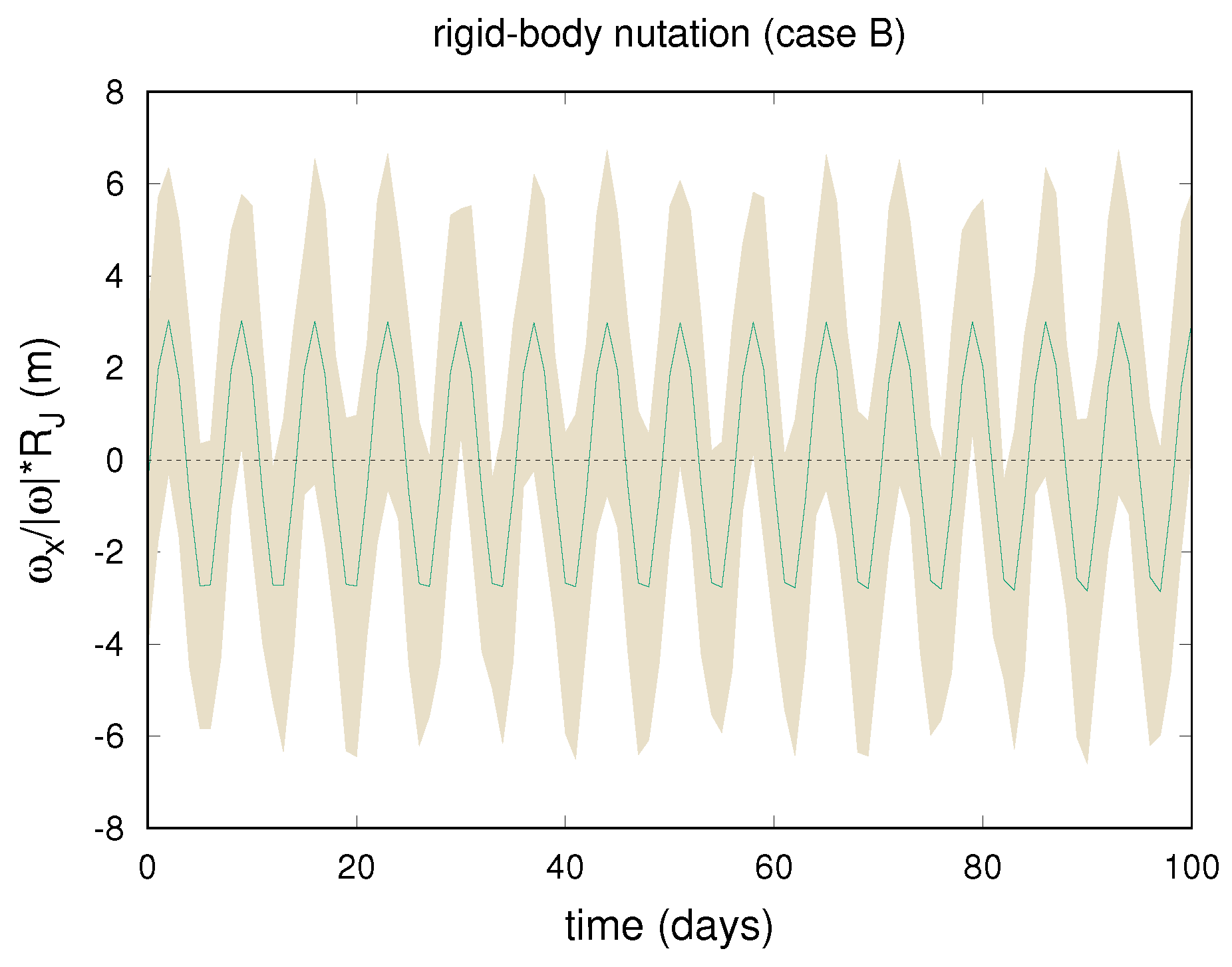
From Figure 6, we can appreciate the period of circulation of ω in the body-fixed reference frame, which is around 7 days. It is worth noting that the obtained free nutation (i.e., not forced by external torques) is the result of the rigid-body dynamics only. However, atmospheric and interior processes can introduce other terms in the nutation motion with very different periods, as is the case for the Earth [24]. Even though it is out of the scope of this paper to model or speculate about possible effects that may cause Jupiter’s pole to wobble, in Section 4 we discuss the sensitivity of Juno data to such phenomena.
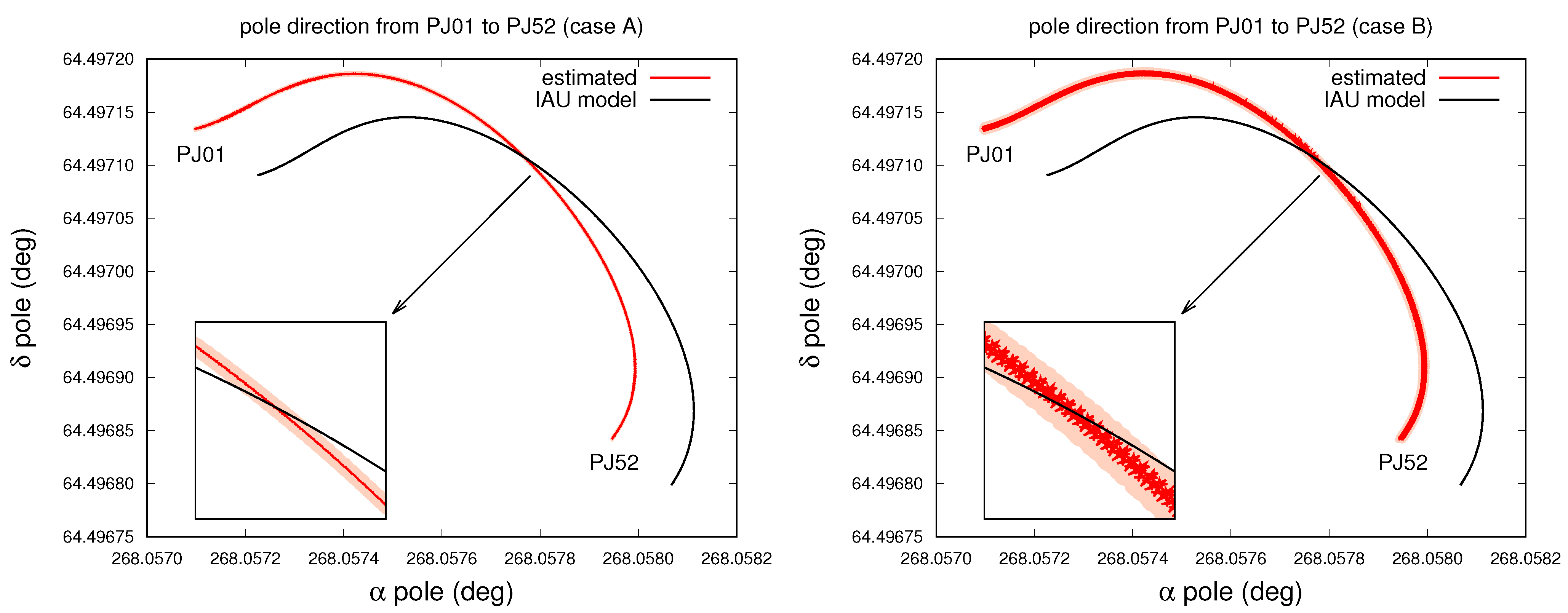
As already mentioned, the displacement between the pole direction and the spin axis found in case B produces a short-period nutation in the motion of the pole of the planet. In Figure 7, we can see the difference in the pole path in the case with no displacement (case A) and with the found nominal displacement of 3 m (case B), both compared with the IAU model. The evolution is restricted to the duration of the Juno mission (now around 7 years); the red line is the estimated nominal solution, while the orange area represents its 3- σ uncertainty. Both red curves differ clearly from the IAU kinematic model (black curve), highlighting the importance of Juno data to improve the ephemerides of Jupiter’s orientation. The two solutions A and B are almost identical on the larger timescale (years), but from the zoom in Figure 7, we can see the difference for the shorter timescale (days). In case A, the red curve is smooth, like the black one. In case B, the red curve presents evident oscillations, whose period corresponds to the rotation period of Jupiter (around 10 h); this is the result of the displacement between the spin axis and pole which we observe in Figure 5 and have already discussed. It is worth noting that these oscillations are compatible with Juno data, in the sense that we manage to fit the extremely accurate Doppler data of Juno even including this short-period nutation. Indeed, the final value of the target function Q is identical in the two experiments. However, we stress that the oscillation’s amplitude is compatible with zero, so we can provide only an upper bound on its value, which corresponds to about 10 7 radians. From Figure 7, we can note that the uncertainty in the position of the pole during the evolution is larger in the second case than in the first one, as can be expected from the values reported in Table 2.

4. Discussion

In Section 3, we considered the possibility that the spin axis of Jupiter is not perfectly aligned with its pole direction. We did not obtain a clear determination of a displacement, but we provided an upper bound. To obtain this result, we implemented a dynamical model for the rotation of Jupiter, for which we considered both the rigid contribution I rig to the matrix of inertia and its tidal deformation I var .
In this section, we further discuss the sensitivity of Juno to possible Jupiter’s pole oscillations and we evaluate the effect of normal modes on the rotational dynamics of the planet.

4.1. Sensitivity of Juno to Pole’s Oscillations

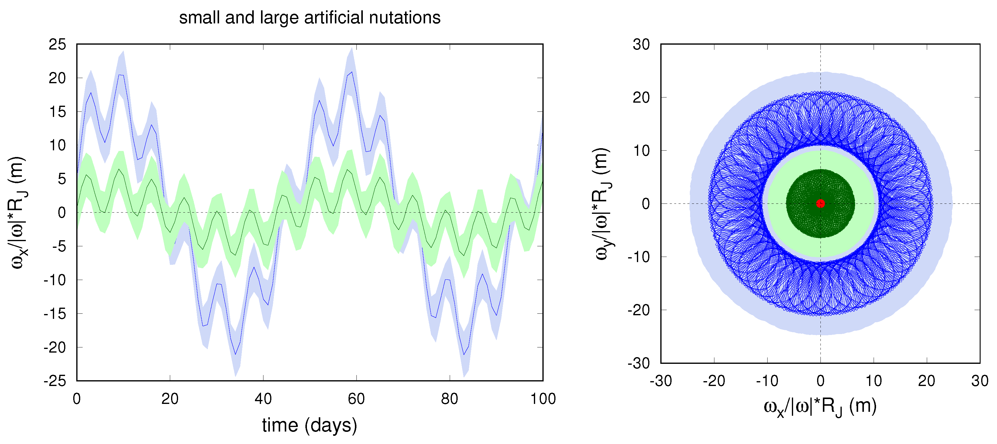
With our model, we could reproduce the medium and long-period nutations of Jupiter due to the external torques of the Galilean satellites (see Figure 1), but also the free short-period nutation resulting from the rigid-body dynamics (see Equation (8)). However, the planet’s nutations could arise also from the effect of atmospheric and interior processes. These phenomena can add signals in the free nutation of the planet with very different frequencies and amplitudes. In order to test the possibility of Juno to detect such effects, we artificially add them to the rotation evolution of Jupiter. In fact, we do not model their complex and unknown contribution to the dynamics, but we directly force a nutation in the pole’s motion through the formulas
ω ˙ x new = ω ˙ x + A ν cos ( ν t ) , ω ˙ y new = ω ˙ y + A ν sin ( ν t ) ;
where we can choose both the amplitude A and frequency ν . This is clearly a simplification, as the variable nature of such phenomena makes these quantities not constant. However, considering the limited time span of the mission, it is a suitable approximation for our purposes.
In Figure 8, we reported two examples where we fixed the nutation period to 50 days and we considered two different amplitudes. The induced signal of period 50 days and the rigid-body nutation of period 7 days are evident in the plot. From a comparison with the 3- σ uncertainty, we see that, if the displacement of the spin axis is large enough (≳10 m on the surface of Jupiter, as for the blue curve), the nutation could be detected from Juno data. This is true provided that the nutation model is perfectly known; otherwise, other sources of errors would produce an increase in the uncertainty of the spin axis direction.
Instead, if the displacement is small (<10 m on the surface of Jupiter, such as for the green curve), its effect on Jupiter’s pole remains almost invisible to Juno’s radio science data. Indeed, adding or removing it from the dynamics does not significantly change the target function value at the convergence of the differential corrections.
In the end, possible processes and effects that affect Jupiter’s pole orientation can be tested through the analysis of Juno’s radio science data. Their dynamical effect can be included in the model and, if the resulting nutation is large enough, it should be visible in the data. If the effect is real, it should contribute to lowering the total target function of the residuals; otherwise, we expect a worse fit of the data, with an increase in the target function that depends on the amplitude of the included nutation. For the two random effects we considered as examples, we see that, in the case of small amplitude, the target function increases by about 2‰ (almost negligible); instead, for the larger amplitude, the target function increases by about 2 % .

4.2. Normal Mode’s Effect

Normal modes within the interior of Jupiter are associated with variations in the mass distribution of the planet, which perturb its gravity field [17]. The total gravity signal of these effects is lower than 10 1 mm/s, which is quite small but greater than the signal-to-noise limit of Juno Doppler data (see Figure 4 for comparison). Apart from tides, normal modes are the major source of a clear non-zonal or time-variable gravity signal found in the Juno radio science data (see Equation (7)). Because of their very short characteristic periods (from fewa minutes to a few hours), when we include the normal mode’s contribution to the rotational model, we cannot neglect the term I ˙ ω in Equation (8).
In the previous analysis of radio science data, normal modes have been considered as local parameters; in particular, for each mode included in the dynamical model, we estimated an equivalent of a local amplitude and phase, while we considered the frequency known. This choice is due to the very short period of normal modes and to the sporadic observation intervals of Juno, which make a global analysis of these effects not feasible.
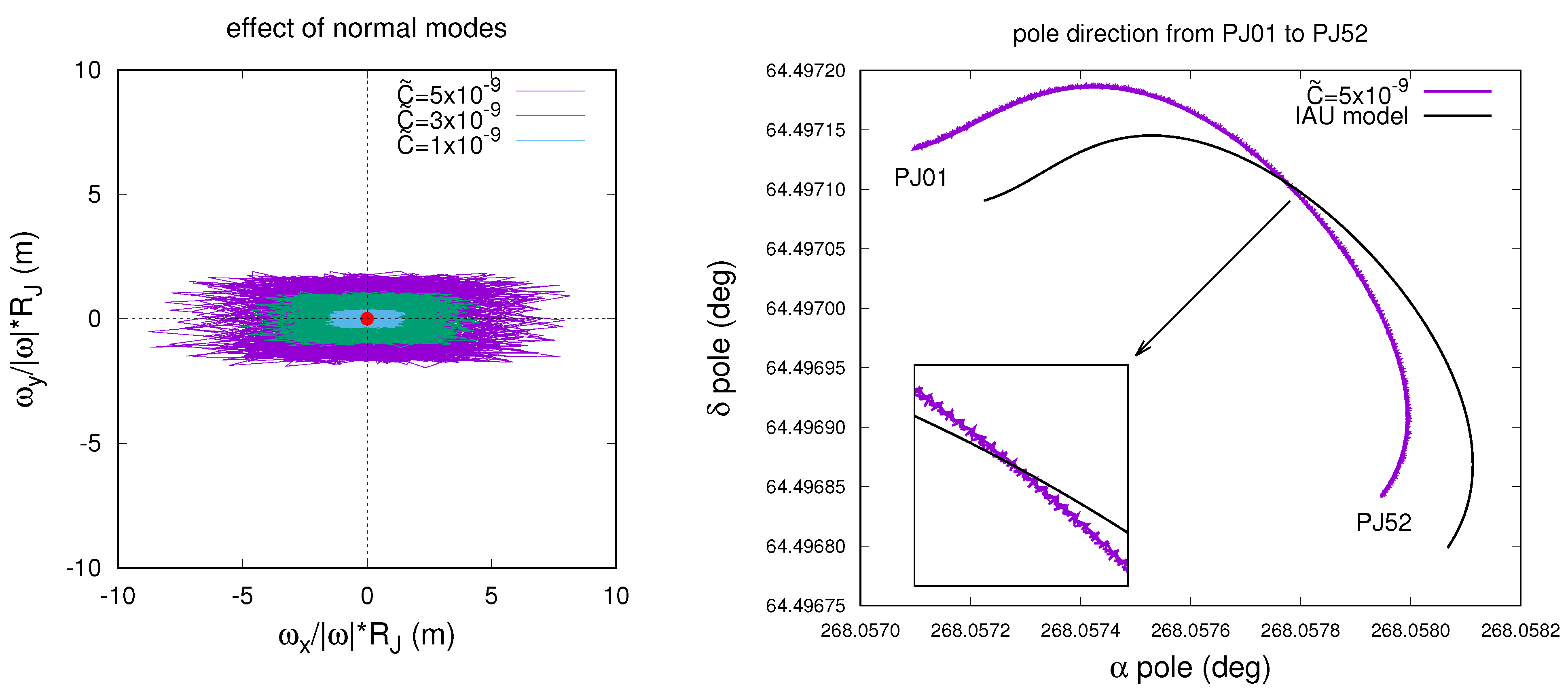
While for Juno’s dynamics, this kind of strategy is reasonable, as we propagate the spacecraft’s state for only a few hours during the PJs (multi-arc strategy), we cannot consider local normal modes for the rotation dynamics of Jupiter. In fact, we propagate the orientation of Jupiter for the whole duration of the mission, so that the dynamical model must be coherent within this interval of about 7 years. Therefore, in order to evaluate the possible effect of the normal modes on the rotational dynamics, we set all their amplitudes to three fixed values compatible with the results presented by Durante et al. [17], which are C ˜ m n 1 , 3 , 5 × 10 9 (smaller, equal and larger than the adopted a priori, respectively). In the same paper, the authors considered normal modes contribution only to zonal parameters J , in order not to overparameterize the orbit determination process. Since we are interested in possible nutation effects due to normal modes, in this analysis we consider a variation in the tesseral quadrupole coefficient C 21 similar to the one expected for J 2 .
In Figure 9, we reported the total effect of the considered normal modes on the spin axis of Jupiter. Because of the fast periodic nature of the variation of C 21 , the spin axis does not circulate around the pole, but it oscillates wildly over it, so that on average, its displacement is almost null. Therefore, even though the maximum reached displacement is around 2, 5 and 8 m, respectively, the amplitude of the pole’s oscillation is generally smaller than the case of a constant displacement (compare the right plot of Figure 9 with Figure 7). In the maximum case C ˜ m n 5 × 10 9 , the oscillation amplitude is lower than 10 7 radians; therefore, the effect of normal modes on the orientation of Jupiter remains invisible to Juno radio science data.
In order to confirm this, we performed an orbit determination experiment where we added the contribution of normal modes in the matrix of inertia for the propagation of Jupiter’s orientation. For all three magnitudes that we considered for the normal modes’ amplitudes, the final value of the target function did not change (<1‰) with respect to an experiment without this contribution, which means that the residuals remained almost the same. Moreover, the estimation of all fit parameters was unaffected.

5. Conclusions

In this work, we processed Juno’s radio science data in order to determine precisely Jupiter’s orientation in space. We found a clear correction in the initial pole direction with respect to the IAU model [14] of the order of 10 6 radians (3- σ uncertainty of about 10 7 radians), which allows us to better constrain its ephemerides. Moreover, we investigated the existence of a free short-period nutation of Jupiter; although we did not manage to obtain a clear determination, we were able to provide a bound on its amplitude. More precisely, we found that radio science data allow a maximum possible displacement between Jupiter’s pole and spin axis of less than 10 m, resulting in a short-period free nutation with a maximum amplitude of 10 7 radians. The reported values are intended as upper bounds; indeed, considering the obtained 3- σ uncertainty, solutions with much smaller, or even null, free nutation are compatible with the data.
The estimated values and uncertainties of the initial position of the pole presented in this paper represent an improvement with respect to previous solutions [4,23] and they can be used for accurate investigations of Jupiter’s rotational dynamics, including propagations over longer timescales (see, e.g., [21]).
We reported the also estimated values of the static tesseral quadrupole coefficients of Jupiter, whose effects were included both in the spacecraft’s dynamics (gravity field) and Jupiter’s rotation (inertia components). For all parameters, we obtained nominal values of the order of 10 10 and then, given their formal uncertainties, they are all compatible with 0 at a level < 1.5 - σ , as expected for gas giants and in agreement with previous estimations [4,28].
Precise determination of the rotation of a planet is an important piece of information to understand its interior and dynamics, as shown recently for Mars [36]. Indeed, precession and nutation motions can be the result not only of external torques, but also of atmospheric or interior processes. Depending on the characteristic timescales of such phenomena, it is possible that they can be visible in the radio science data as gravity signals and/or induced nutations of the planet. Therefore, through the determination of the planet’s orientation, it is possible to explore and possibly detect these processes, provided that they produce an amplitude in the pole oscillations larger than its estimated uncertainty. As an example, we investigated the maximum possible contribution of the normal modes within Jupiter. We found that their effect on the rotational dynamics is not visible in the Juno radio science data, as normal modes’ timescale is extremely short and the maximum amplitude in the nutation remains below the estimated limit of 10 7 radians.

Author Contributions

Conceptualization, G.L. and M.Z.; methodology, G.L., M.Z., D.D. and R.S.P.; software, G.L. and G.T.; validation, G.L., M.Z., D.D. and R.S.P.; formal analysis, G.L.; investigation, G.L.; resources, G.L. and G.T.; data curation, G.L., M.Z., D.D. and R.S.P.; writing—original draft preparation, G.L.; writing—review and editing, G.L.; visualization, G.L.; supervision, G.T.; project administration, G.T.; funding acquisition, G.T. All authors have read and agreed to the published version of the manuscript.

Funding

This work was funded in part by the Italian Space Agency (ASI) through agreement no. 2022-16-HH.0. Part of this research was carried out at the Jet Propulsion Laboratory, California Institute of Technology, under a contract with the National Aeronautics and Space Administration. Orbit14 software has been developed with the financial support by ASI.

Data Availability Statement

All Juno radio science data used in this article are publicly available through NASA-PDS.

Conflicts of Interest

The authors declare no conflicts of interest.

References

  1. Bolton, S.J.; Lunine, J.; Stevenson, D.; Connerney, J.E.P.; Levin, S.; Owen, T.C.; Bagenal, F.; Gautier, D.; Ingersoll, A.P.; Orton, G.S.; et al. The Juno Mission. Space Sci. Rev. 2017, 213, 5–37. [Google Scholar] [CrossRef]
  2. Asmar, S.W.; Bolton, S.J.; Buccino, D.R.; Cornish, T.P.; Folkner, W.M.; Formaro, R.; Iess, L.; Jongeling, A.P.; Lewis, D.K.; Mittskus, A.P.; et al. The Juno Gravity Science Instrument. Space Sci. Rev. 2017, 213, 205–218. [Google Scholar] [CrossRef]
  3. Iess, L.; Folkner, W.M.; Durante, D.; Parisi, M.; Kaspi, Y.; Galanti, E.; Guillot, T.; Hubbard, W.B.; Stevenson, D.J.; Anderson, J.D.; et al. Measurement of Jupiter’s asymmetric gravity field. Nature 2018, 555, 220–222. [Google Scholar] [CrossRef]
  4. Durante, D.; Parisi, M.; Serra, D.; Zannoni, M.; Notaro, V.; Racioppa, P.; Buccino, D.R.; Lari, G.; Gomez Casajus, L.; Iess, L.; et al. Jupiter’s Gravity Field Halfway Through the Juno Mission. Geophys. Res. Lett. 2020, 47, e86572. [Google Scholar] [CrossRef]
  5. Wahl, S.M.; Hubbard, W.B.; Militzer, B.; Guillot, T.; Miguel, Y.; Movshovitz, N.; Kaspi, Y.; Helled, R.; Reese, D.; Galanti, E.; et al. Comparing Jupiter interior structure models to Juno gravity measurements and the role of a dilute core. Geophys. Res. Lett. 2017, 44, 4649–4659. [Google Scholar] [CrossRef]
  6. Guillot, T.; Miguel, Y.; Militzer, B.; Hubbard, W.B.; Kaspi, Y.; Galanti, E.; Cao, H.; Helled, R.; Wahl, S.M.; Iess, L.; et al. A suppression of differential rotation in Jupiter’s deep interior. Nature 2018, 555, 227–230. [Google Scholar] [CrossRef] [PubMed]
  7. Kaspi, Y.; Galanti, E.; Hubbard, W.B.; Stevenson, D.J.; Bolton, S.J.; Iess, L.; Guillot, T.; Bloxham, J.; Connerney, J.E.P.; Cao, H.; et al. Jupiter’s atmospheric jet streams extend thousands of kilometres deep. Nature 2018, 555, 223–226. [Google Scholar] [CrossRef] [PubMed]
  8. Stevenson, D.J. Jupiter’s Interior as Revealed by Juno. Annu. Rev. Earth Planet. Sci. 2020, 48, 465–489. [Google Scholar] [CrossRef]
  9. Kaspi, Y.; Galanti, E.; Park, R.S.; Duer, K.; Gavriel, N.; Durante, D.; Iess, L.; Parisi, M.; Buccino, D.R.; Guillot, T.; et al. Observational evidence for cilindrically oriented zonal flows on Jupiter. Nat. Astron. 2023, 7, 1463–1472. [Google Scholar] [CrossRef]
  10. Gomez Casajus, L.; Ermakov, A.I.; Zannoni, M.; Keane, J.T.; Stevenson, D.; Buccino, D.R.; Durante, D.; Parisi, M.; Park, R.S.; Tortora, P.; et al. Gravity Field of Ganymede After the Juno Extended Mission. Geophys. Res. Lett. 2022, 49, e2022GL099475. [Google Scholar] [CrossRef]
  11. Hansen, C.J.; Bolton, S.; Sulaiman, A.H.; Duling, S.; Bagenal, F.; Brennan, M.; Connerney, J.; Clark, G.; Lunine, J.; Levin, S.; et al. Juno’s Close Encounter With Ganymede—An Overview. Geophys. Res. Lett. 2022, 49, e2022GL099285. [Google Scholar] [CrossRef] [PubMed]
  12. Phillips, C.B.; Pappalardo, R.T. Europa Clipper Mission Concept: Exploring Jupiter’s Ocean Moon. Eos 2014, 95, 165–167. [Google Scholar] [CrossRef]
  13. Grasset, O.; Dougherty, M.K.; Coustenis, A.; Bunce, E.J.; Erd, C.; Titov, D.; Blanc, M.; Coates, A.; Drossart, P.; Fletcher, L.N.; et al. JUpiter ICy moons Explorer (JUICE): An ESA mission to orbit Ganymede and to characterise the Jupiter system. Planet. Space Sci. 2013, 78, 1–21. [Google Scholar] [CrossRef]
  14. Archinal, B.A.; Acton, C.H.; A’Hearn, M.F.; Conrad, A.; Consolmagno, G.J.; Duxbury, T.; Hestroffer, D.; Hilton, J.L.; Kirk, R.L.; Klioner, S.A.; et al. Report of the IAU Working Group on Cartographic Coordinates and Rotational Elements: 2015. Celest. Mech. Dyn. Astron. 2018, 130, 22. [Google Scholar] [CrossRef]
  15. Folkner, W.M.; Iess, L.; Anderson, J.D.; Asmar, S.W.; Buccino, D.R.; Durante, D.; Feldman, M.; Gomez Casajus, L.; Gregnanin, M.; Milani, A.; et al. Jupiter gravity field estimated from the first two Juno orbits. Geophys. Res. Lett. 2017, 44, 4694–4700. [Google Scholar] [CrossRef]
  16. Parisi, M.; Kaspi, Y.; Galanti, E.; Durante, D.; Bolton, S.J.; Levin, S.M.; Buccino, D.R.; Fletcher, L.N.; Folkner, W.M.; Guillot, T.; et al. The depth of Jupiter’s Great Red Spot constrained by Juno gravity overflights. Science 2021, 374, 964–968. [Google Scholar] [CrossRef]
  17. Durante, D.; Guillot, T.; Iess, L.; Stevenson, D.J.; Mankovich, C.R.; Markham, S.; Galanti, E.; Kaspi, Y.; Zannoni, M.; Gomez Casajus, L.; et al. Juno spacecraft gravity measurements provide evidence for normal modes of Jupiter. Nat. Commun. 2022, 13, 4632. [Google Scholar] [CrossRef]
  18. Le Maistre, S.; Folkner, W.M.; Jacobson, R.A.; Serra, D. Jupiter spin-pole precession rate and moment of inertia from Juno radio-science observations. Planet. Space Sci. 2016, 126, 78–92. [Google Scholar] [CrossRef]
  19. Serra, D.; Dimare, L.; Tommei, G.; Milani, A. Gravimetry, rotation and angular momentum of Jupiter from the Juno Radio Science experiment. Planet. Space Sci. 2016, 134, 100–111. [Google Scholar] [CrossRef]
  20. Ward, W.R.; Canup, R.M. The Obliquity of Jupiter. Astrophys. J. 2006, 640, L91. [Google Scholar] [CrossRef]
  21. Saillenfest, M.; Lari, G.; Courtot, A. The future large obliquity of Jupiter. Astron. Astrophys. 2020, 640, A11. [Google Scholar] [CrossRef]
  22. Dbouk, R.; Wisdom, J. The Origin of Jupiter’s Obliquity. Planet. Sci. J. 2023, 4, 188. [Google Scholar] [CrossRef]
  23. Jacobson, R.A.; Haw, R.J.; McElrath, T.P.; Antreasian, P.G. A Comprehensive Orbit Reconstruction for the Galileo Prime Mission in the J2000 System. J. Astronaut. Sci. 2000, 48, 495–516. [Google Scholar] [CrossRef]
  24. Smith, M.L. Wobble and nutation of the Earth. Geophys. J. Int. 1977, 50, 103–140. [Google Scholar] [CrossRef]
  25. Milani, A.; Gronchi, G.F. Theory of Orbit Determination; Cambridge University Press: Cambridge, UK, 2010. [Google Scholar]
  26. Serra, D.; Lari, G.; Tommei, G.; Durante, D.; Gomez Casajus, L.; Notaro, V.; Zannoni, M.; Iess, L.; Tortora, P.; Bolton, S.J. A solution of Jupiter’s gravitational field from Juno data with the ORBIT14 software. Mon. Not. R. Astron. Soc. 2019, 490, 766–772. [Google Scholar] [CrossRef]
  27. Tommei, G.; Dimare, L.; Serra, D.; Milani, A. On the Juno radio science experiment: Models, algorithms and sensitivity analysis. Mon. Not. R. Astron. Soc. 2015, 446, 3089–3099. [Google Scholar] [CrossRef]
  28. Lari, G.; Schettino, G.; Serra, D.; Tommei, G. Orbit determination methods for interplanetary missions: Development and use of the Orbit14 software. Exp. Astron. 2022, 53, 159–208. [Google Scholar] [CrossRef]
  29. Wahl, S.M.; Hubbard, W.B.; Militzer, B. Tidal response of preliminary Jupiter model. Astrophys. J. 2016, 831, 14. [Google Scholar] [CrossRef]
  30. Jacobson, R.A. The orbits of the Uranian satellites and rings, the gravity field of the Uranian system, and the orientation of the pole of Uranus. Astron. J. 2014, 148, 76. [Google Scholar] [CrossRef]
  31. Jacobson, R.A. The Orbits of the Main Saturnian Satellites, the Saturnian System Gravity Field, and the Orientation of Saturn’s Pole. Astron. J. 2022, 164, 199. [Google Scholar] [CrossRef]
  32. Burkhard, M.; Hubbard, W.B. Relation of Gravity, Winds, and the Moment of Inertia of Jupiter and Saturn. Planet. Sci. J. 2023, 4, 95. [Google Scholar]
  33. Folkner, W.M.; Williams, J.G.; Boggs, D.H.; Park, R.S.; Kuchynka, P. The planetary and lunar ephemerides DE430 and DE431. Interplanet. Netw. Prog. Rep. 2014, 42–196. [Google Scholar]
  34. Sharma, I.; Burns, J.A.; Hui, C.Y. Nutational damping times in solids of revolution. Mon. Not. R. Astron. Soc. 2005, 359, 79–92. [Google Scholar] [CrossRef]
  35. Seitz, F.; Stuck, J.; Thomas, M. Consistent atmospheric and oceanic excitation of the Earth’s free polar motion. Geophys. J. Int. 2004, 157, 25–35. [Google Scholar] [CrossRef]
  36. Le Maistre, S.; Rivoldini, A.; Caldiero, A.; Yseboodt, M.; Baland, R.M.; Beuthe, M.; Van Hoolst, T.; Dehant, V.; Folkner, W.M.; Buccino, D.; et al. Spin state and deep interior structure of Mars from InSight radio tracking. Nature 2023, 619, 733–737. [Google Scholar] [CrossRef]
Figure 2. Estimation of the pole orientation obtained by Durante et al. [4] through the fit of Juno radio science data from PJ01 to PJ17 using a linear model. The blue dots are the nominal solution at the times of the gravity-dedicated PJs and the ellipses represent their 3- σ uncertainty. In black, we reported the path of the pole from PJ01 to PJ52 as described in the IAU model [14].
Aerospace 11 00124 g002
Figure 3. Representation of the 3-1-3 Euler angles that define the orientation of the body-fixed reference frame of Jupiter with respect to the frame where we study the motion of the spacecraft.
Aerospace 11 00124 g003
Figure 4. Residuals of three different PJs (PJ06, PJ29 and PJ47) at convergence of the differential corrections. In PJ06, we have Ka/Ka data from DSS-25 at the closest approach (C/A) of the perijove and X/X data from DSS-43 post-C/A; in PJ29, we have X/Ka data from DSS-54 pre-C/A, Ka/Ka data from DSS-25 at C/A and X/X data from DSS-35 post-C/A; in PJ47, we have Ka/Ka data from DSS-25 at C/A.
Aerospace 11 00124 g004
Figure 5. Estimated path of the spin vector in the body-fixed reference frame, projected on the polar surface of Jupiter. In green, we reported the nominal solution obtained at the convergence of the differential corrections, while the brownish area is the 3- σ uncertainty. For the first two plots (case A and B), the versor e 3 is a principal axis of inertia and the spin vector moves or circulates around it. In the last plot (case C), the versor e 3 is not a principal axis of inertia ( C 21 0 , S 21 0 ) and the point in red corresponds to the pole.
Aerospace 11 00124 g005
Figure 6. Evolution over 100 days of the component x of ω obtained in case B of our experiments. In green, we reported the nominal solution and the brownish area corresponds to its 3- σ uncertainty. The solution is compatible with null or very small oscillation amplitudes.
Aerospace 11 00124 g006
Figure 7. Estimated path of Jupiter’s pole in the ICRF during the time of the Juno mission, described by its right ascension α and declination δ . In red, we report the nominal solution obtained at the convergence of the differential corrections, while the orange area is the 3- σ uncertainty. In black is the pole path expected from the IAU model [14]. In the first plot (case A), the curve is almost smooth, while in the second plot (case B), there are evident oscillations due to a (small) displacement between the pole and the spin axis of Jupiter.
Aerospace 11 00124 g007
Figure 8. Evolution over 100 days of the spin axis direction ω obtained for two different nutation motions artificially added into the dynamical model of Jupiter. The blue curve represents the case of large amplitude (>10 m on the surface of Jupiter). The green curve, instead, represents the case of small amplitude (<10 m).
Aerospace 11 00124 g008
Figure 9. On the left, path of the spin vector in the body-fixed reference frame, projected on the polar surface of Jupiter, considering fixed normal modes’ amplitudes C ˜ m n = 1 , 3 , 5 × 10 9 for the C 21 parameter. On the right, the oscillation of the pole direction in the case C ˜ m n = 5 × 10 9 .
Aerospace 11 00124 g009
Table 1. Initial conditions of the Euler angles (in radians and radians per day) at epoch 2020.0 (1 January 2020 00:00 TDB) in the ICRF, computed from the IAU model [14].
φ 0 IAU (rad) θ 0 IAU (rad) ψ 0 IAU (rad) φ ˙ 0 IAU (rad/d) θ ˙ 0 IAU (rad/d) ψ ˙ 0 IAU (rad/d)
6.249286360584 0.445109275175 1.311824372389 1.00676 × 10 8 0.26157 × 10 8 15.19371945714
Table 2. Estimated values of the fit parameters involved in the rotational dynamics of Jupiter. We show the results of three different cases (see text for detailed description), while in the last column, we report the reference initial value of the parameters. We do not show the estimated value for λ , as in these experiments, the moment of inertia is tightly constrained by a priori knowledge obtained from interior models of Jupiter [32].
Case ACase BCase CReference Value
φ 0 φ 0 IAU ( 10 8 rad) 198.12 ± 4.98 207.36 ± 8.76 201.88 ± 29.39 0
θ 0 θ 0 IAU ( 10 8 rad) 75.01 ± 4.35 77.38 ± 6.28 75.91 ± 26.00 0
φ ˙ 0 ( 10 8 rad/day)- 67.07 ± 163.45 28.95 ± 928.00 1.01
θ ˙ 0 ( 10 8 rad/day)- 62.41 ± 48.07 20.96 ± 193.58 0.26
C 21 ( 10 10 )-- 4.62 ± 38.40 0
S 21 ( 10 10 )-- 0.48 ± 20.93 0
C 22 ( 10 10 )- 2.43 ± 7.62 2.87 ± 7.62 0
S 22 ( 10 10 )- 2.91 ± 7.05 3.16 ± 7.06 0
Disclaimer/Publisher’s Note: The statements, opinions and data contained in all publications are solely those of the individual author(s) and contributor(s) and not of MDPI and/or the editor(s). MDPI and/or the editor(s) disclaim responsibility for any injury to people or property resulting from any ideas, methods, instructions or products referred to in the content.