Article

Numerical Study on Pressure Oscillations in a Solid Rocket Motor with Backward Step Configuration Under Two-Phase Flow Interactions

School of Astronautics, Northwestern Polytechnical University, Xi’an 710124, China
*
Author to whom correspondence should be addressed.
Aerospace 2024, 11(12), 1054; https://doi.org/10.3390/aerospace11121054
Submission received: 18 November 2024 / Revised: 12 December 2024 / Accepted: 17 December 2024 / Published: 23 December 2024
(This article belongs to the Section Aeronautics)

Abstract

:
The pressure oscillation caused by vortex–acoustic coupling is one of the main gain factors that results in the combustion instability of motors. Focusing on a solid rocket motor with a backward step configuration that can generate a corner vortex, this study aims to investigate the pressure oscillation characteristics in a combustion chamber under two-phase flow interactions through numerical simulations. The two-phase flow discrete phase model (DPM) was chosen to study particle motion and two-phase interactions. The numerical methodology was hence established by coupling the DPM with the large eddy simulation (LES) method. Taking the Clx motor as a reference and introducing aluminum oxide particles, two important particle parameters (diameter and concentration) and the key geometric parameters of the backward step were numerically studied. The numerical results show that both increased particle diameter and concentration can decrease the frequency and amplitude of pressure oscillations; additionally, the effects of geometric parameters on the pressure oscillations of the backward step, such as the downstream aspect ratio, the expansion ratio, and the step position, are basically consistent under both pure gas and two-phase flows. The influences of those geometric parameters are mainly reflected in defining the space for the development of upstream flow instability and the motion of downstream vortices. Compared with the pure-gas flow, the presence of aluminum oxide particles in two-phase flow globally decreases the vortex shedding frequency, the primary frequency, and the amplitude of pressure oscillations. It can also weaken the effects of vortex–acoustic coupling due to increased turbulent viscosity, which hinders the orderly development of vortices.

1. Introduction

The instabilities of solid rocket motors upon combustion cause problems that have been troubling designers for a long time. The solid rocket engines used by missiles and large boosters, such as the Titan booster and the large segmental booster P230 used by Ariane 5, have repeatedly exhibited serious combustion instability issues [1,2]. The combustion instability of a solid rocket motor involves multiple factors, such as distributed combustion, flow resistance, structure damping, and so on [3]. Upon thorough investigation, it has been discovered that the propellant combustion response and vortex–acoustic coupling are the most common factors that cause pressure oscillations. During the operation of a solid rocket motor, unsteady flow causes vortices. If the frequency of vortex shedding couples with the natural frequency of the engine, this can cause acoustic oscillations and enhance pressure oscillations in the combustion chamber. This can result in instability and even in explosion of the motor in extreme cases [4]. Based on previous studies, it was indicated that vortex shedding presenting in motors can possibly cause pressure oscillations [5].
As observed in previous studies of solid rocket motors, such as the Titan 34D and the Space Shuttle [5,6], most pressure oscillations in large segmental solid rocket motors are caused by vortex shedding. For segmented solid rocket motors, the ablative rate of the adiabatic ring located between the segments is lower than the propellant combustion regression rate, which eventually leads to its protrusion from the propellant surface after a certain period of time. Obstacles to the flow are therefore generated, which results in the periodic shedding of vortices. Moreover, during the operation of engines, periodic vortex shedding can also occur at the backward step of the finocyl grain. When the frequency of vortex shedding is close to the acoustic frequency of the combustion chamber, pressure oscillations are further enhanced. Regardless of the cause of the vortex shedding, the working process of engines is significantly impacted. Over a long time, researchers have found that adding metal particles can solve combustion instability problems [7,8]. However, as motor performance requirements have increased, high-burning-rate propellant and grain configurations with complex layouts have increasingly been applied, which cause a further complication of the flow state within the combustion chamber. Specifically, in a combustion chamber with a finocyl grain configuration, the backward step of the axisymmetric structure occurs. Meanwhile, the condensed particles released during the combustion of a high-energy propellant that contains metal particles affect the generation and shedding of vortices in the flow field and further change the acoustic characteristics and pressure oscillations.
In 1973, Flandro and Jacobs [9] examined the transient nonlinear effects of unsteady flow separation within a cavity upon the occurrence of sound waves. They first proposed that vortex shedding is one of several mechanisms that drive pressure oscillations in motors. Using experimental data, Dunlap et al. demonstrated that a vortex couples with acoustics when their frequencies are close; this can further cause pressure oscillations [10]. In 1990, Culick et al. revealed that a strong coupling leads to, in addition to acoustic oscillation, vortex motion, turbulent fluctuation, and particle dynamics when the two-phase flow interacts with the externally imposed acoustics [11]. K.W. Dotson et al. proposed a four-step model for vortex formation, shedding, collision, and acoustic feedback. They provided a theoretical foundation for researchers to explore the vortex–acoustic coupling mechanism [12]. Based on their work, researchers have been continuously studying vortex–acoustic coupling in solid rocket motors. In 2002, Sourabh Apte et al. compared the flow in tubes with and without the application of acoustic waves by using the two-dimensional large eddy simulation method. It was indicated that the interaction of turbulent motion and acoustic motion leads to significant changes in the evolution of unsteady flow in the chamber [13,14]. Cai et al. also computed two-phase interactions in a solid rocket motor using the combined Euler–Lagrange method. It was indicated that the influence of particles on the flow field mainly depends on their relaxation time and the characteristic time of the acoustic waves [15]. Their work emphasized the interactions of two-phase flows; however, their effects on pressure oscillations were not indicated. The grain configuration, namely the internal flow field, affects flow stability. Based on both numerical simulations and experimental results, researchers have proposed that axil grain is more stable than finocyl grain in low-order acoustic modes [16]. Different working mediums can induce distinct flow characteristics under the same configuration. The presence of two phases may affect the flow state [17]. Some numerical studies have been conducted on two-phase flows using Clxb and VKI [18,19]. The drag force that a gas exerts on particles primarily affects their axial velocity [20], and it has been revealed that two-phase flow can affect the vortex motion and coupling between vortices and acoustics in combustion chambers [21,22]. In addition, variations in upstream flow development have a significant effect on the pressure oscillation behind the step [23,24].
In conclusion, previous studies have mostly focused on pure-gas flows and have predominantly examined the vortex–acoustic coupling phenomenon and its effects on flow instability. However, for practical engineering applications, metal-based propellants are often used to enhance the performance of motors. The effect of the condensation of phase products, caused by particle combustion, on vortex motion and pressure oscillations in motors has not been addressed in previous research. Therefore, this study aims to clarify the influence of aluminum oxide particles, which are often generated in the combustion chambers of solid rocket motors. The flow characteristics of pure gas and two-phase fluids were compared, and the vortex motion and pressure oscillations in both flow conditions were analyzed. Two important parameters of particles (diameter and concentration) and the key geometric parameters of the backward step, such as the downstream aspect ratio, expansion ratio, and step position, were further calculated to clarify the influence of particles.

2. Numerical Methodology

2.1. Large Eddy Simulation Method

The physical model used in this work is the self-oscillating experimental motor Clx [25]. A typical backward step structure is formed due to the finocyl grain in the combustion process. The upstream flow instability generates a vortex when crossing the step. This vortex moves and develops in the downstream direction along with the main flow. Subsequently, it may collide with the nozzle and interact with the acoustic field. Therefore, it is evident that the numerical methodology proposed in this paper should accurately capture the vortex motion. Currently, turbulence models that can simulate turbulence with vortex motion are mainly classified into several methods, such as Reynolds time-averaged Navier–Stokes equations (RANS), direct numerical simulation (DNS), and large eddy simulation (LES) [26]. However, the RANS method is only applicable to the turbulent environment with a small Reynolds number, and the DNS method yields high accuracy but requires substantial calculations. Taking into account the research object under study, the LES was chosen. The LES spatially averages the Navier–Stokes equation, filters out vortices smaller than the filter mesh size, and thus obtains the momentum equation of the large vortices on a resolvable scale. To account for the effects of small-scale vortices on large vortices, a subgrid-scale model (SGS) was used to close the entire equation [27]. The injection of particles into the flow field occurs because of chemical reactions. Since studying the effects of particles was the first step in this study, chemical reactions are not considered. The continuity, momentum, and energy equations in the X-axis direction are obtained after filtering the N-S equation as follows. The governing equations in the y and z directions can be presented in the same way.
Continuity equation:
ρ ¯ t + ρ ¯ u ~ i x i = 0
Momentum equation:
t ρ ¯ u ~ i + x i ρ ¯ u ~ i u ~ j = p ¯ x i + t ( σ ~ i j τ i j s g s )
Energy equation:
t ρ ¯ e ~ + x i ρ ¯ u ~ i e ~ = x i ( p ¯ u ~ i q ¯ i + u ~ i σ ~ i j H i s g s Θ i s g s ) ,
where “-” represents the Reynolds average and “~” represents the Favre average. τ i j is the subgrid tension, defined as τ i j ρ u i u j ~ ρ u ~ i u ~ j . After filtering, the viscous stress σ ¯ i j and heat flux q ~ i of the molecule are expressed below.
σ ~ i j = μ u ~ i x j + u ~ j x i 2 3 μ u ~ k x k δ i j
q ¯ i = K ¯ T ~ x i ,
where μ is the dynamic viscosity coefficient; the thermal conductivity is K ¯ = C p μ / P r . The gas working medium is treated as an ideal gas.
As the subgrid tension after filtering is unknown, the WALE subgrid model [28] is selected due to its higher model accuracy and lower dissipation. In the WALE subgrid model, the subgrid heat flux tensor H i s g s is defined as follows:
H i s g s = H i x i μ t p r
The sublattice-scale viscous force deformation work Θ i s g s is defined in (7).
Θ i s g s = c ε ρ ¯ k s g s 2 / 3 V 1 / 3 ,
where the constant C ε is 1.1.

2.2. Numerical Model of Two-Phase Flow

In order to improve the specific impulse of solid rocket motors, metal particles such as aluminum powder are often used in the propellant. Particles such as aluminum oxide are produced in the process of metal combustion and flow out with the gas. In this work, we employed the discrete phase model (DPM) to calculate the trajectory of discrete particles (droplets or solid particles) in two-phase flow [29]. The motion trajectories of discrete particles are solved by integrating the force differential equations of the particles in the Cartesian coordinate system. The Cartesian coordinate form of the differential equation for the force balance (various forces acting on the surface and volume of the particles) along the x direction is as follows [30].
d v k d t = F D ( u v k ) + g x ( ρ k ρ ) ρ k + F x
In this equation, the body force F D of the particle can be calculated by Equation (9).
F D = 18 μ ρ k d P 2 C D Re 24
where u is the fluid flow velocity, v k is the particle motion velocity, μ is the dynamic viscosity of the fluid, ρ is the unit density of the fluid, ρ k is the unit density of the particle, d p is the average diameter of the particle, C D is the drag coefficient, and Re is the relative Reynolds number of the particle, with a magnitude as follows.
Re = ρ d p v k u μ
The computation of drag force is directly associated with the all-round calculation of particle movement, fluid flow, and interphase coupling. Based on the coupling relationship between the drag force equilibrium and the two phases in the two-fluid model [31], the drag force can be calculated as follows.
( f d ) k = ( V p ) k β k 1 ε k ( u k v k ) k = 1 , , N
where ( f d ) k represents the drag force exerted on particle k , ( V p ) k is the volume of particle k , v k is the particle velocity, and ε k and β k , respectively, denote the local void fraction and local interphase momentum exchange coefficient of particle k . u k is the virtual gas velocity at the centroid of particle k . When ε k < 0.8, β k is given by the Ergun equation [32]; when ε k ≥ 0.8, it is given by the correlation of Wen and Yu [33].
β k = 150 ( 1 ε k ) 2 ε k μ g ( d p ) k 2 + 1.75 ( 1 ε k ) ρ g ( d p ) k u k v k ε k < 0.8 β k = 3 4 ( C d 0 ) k ε k ( 1 ε k ) ( d p ) k ρ g u k v k ε k 2.65          ε k 0.8
where μ g and ρ g are the volume viscosity coefficient and density of the gas, respectively. The single-particle drag coefficient of particle k is
( C d 0 ) k = 24 ( Re p ) k 1 + 0.15 ( Re p ) k 0.687 ( Re p ) k < 1000 0.44            ( Re p ) k 1000
The Reynolds number of particle k in the particle group is
( Re p ) k = ε k ρ g u k v k ( d p ) k μ g

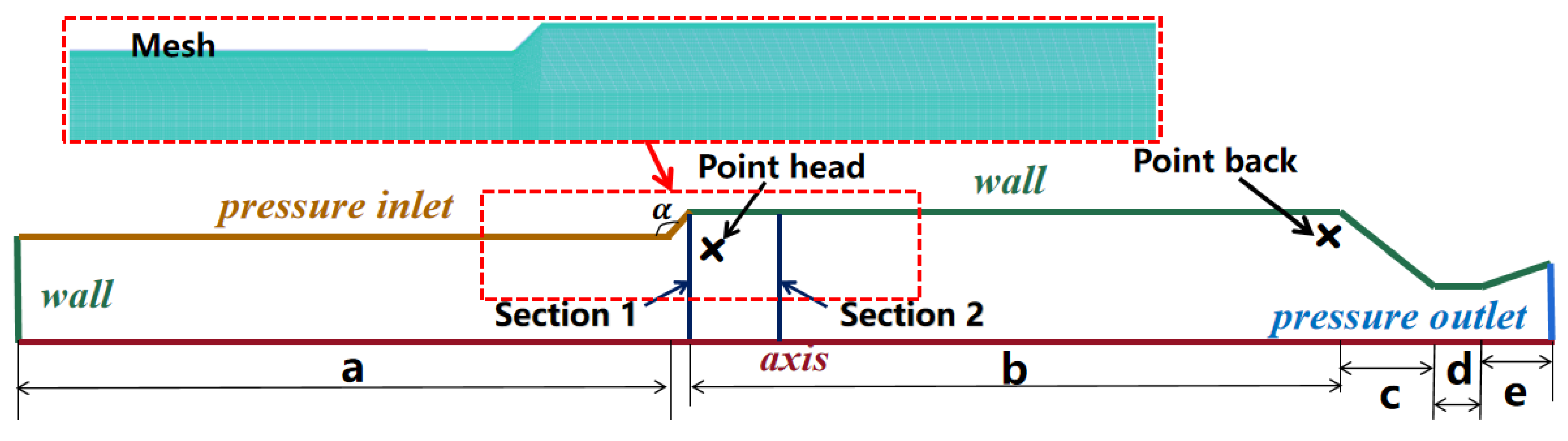
2.3. Physical Model and Numerical Methodology

In this study, the Clx motor is taken as a reference. The Clx motor is a solid experimental motor with self-excited oscillation. It was designed by the French Office National d’Etudes et de Recherches (ONERA) based on a computational model called “MAVOT” [34]. In experiments, ONERA ignited the motor several times and observed an obvious pressure oscillation [35,36]. By using this model, under the condition that its burning surface regression is 11.5 mm, the numerical methodology established above was first verified.
Figure 1 and Table 1 present the physical model and the specific parameters of the axisymmetric Clx, respectively. It can be seen that the Clx motor has a typical finocyl grain, including two cylinders with different diameters and a backward step. The inner diameter is 70 mm in the upstream of the step and 85 mm in the downstream of the step. The overall axial length is 700 mm. The primary geometrical parameters of the backward step include the upstream/downstream aspect ratios of the step, the expansion ratio, and the step position.
The Clx motor is axisymmetric and involves lateral mass combustion. The computational domain only needs to take half of the configuration, as shown in Figure 1. The pressure boundary conditions are defined at the sidewall in the upstream of the step and the outlet of the motor. Other walls are defined as non-slip walls. Structured meshes were generated in all computational areas. The local meshes around walls, steps, and the nozzle are encrypted. In order to obtain pressure oscillations and flow features, several pressure monitoring points and radial cross-sections are set at key positions in the flow field. The frequency and amplitude of pressure oscillations are obtained using fast Fourier transform (FFT) analysis.
Based on the numerical methodology and model presented above, in this study, we chose to use a pressure-based solver. The pressure–velocity coupling and the second-order upwind scheme for spatial discretization were applied to solve the equations [37]. The time step was chosen as 4 × 10⁻⁷ s. Variations in the mass flow rate at the inlet and outlet are monitored. The calculation is considered to be convergent when the residual reaches 1.0−6, and the mass flow rates of imports and exports exhibit consistent changes.
Taking the Clx motor introduced above as a reference, this work used the commercial computational code Fluent as the platform. The numerical methodology established above was first verified in a pure-gas flow. Meanwhile, a numerical study on the key geometric parameters of the backward step was carried out in order to determine the influence of the step configuration on the vortex motion. Additionally, aluminum oxide particles were introduced, and the two-phase flow was calculated. The flow characteristics of the motor with a backward step under two-phase flow interactions and the effects of condensed particles on vortex motion and pressure oscillations were examined.

3. Verification of Numerical Methodology

Based on the numerical methodology established above, the analysis of grid independence was first conducted; then, the numerical methodology using LES was verified. The given specific boundary conditions were the same as those defined in the experiments [38].

3.1. Grid Independence Analysis

Since the flow near the backward step and the wall is complicated, the adjacent area is locally refined to ensure that the ability to capture vortices of different scales is in place. The meshes around the boundary layer, step corner, and cavity corner were carefully refined, where Y+ was made to be as close to 1 as possible. As Figure 2 shows, three sets of meshes were constructed in this study with sequentially increased grid numbers: 140,000, 270,000, and 520,000, respectively.
Table 2 presents the pressure oscillation characteristics based on those three meshes above. It reveals that when the number of grids increases, which means that the grid size decreases, the pressure oscillation under the primary frequency decreases in both its oscillation frequency and amplitude. Continuously increasing the grid number above 270,000 does not bring much change in pressure oscillations at the primary frequency. The amplitude and frequency of the pressure oscillation are decreased by 4.39% and 0.27%, respectively, when compared to 520,000 grids. Therefore, it can be concluded that when the grid number is 270,000 or more, the calculation results are independent of the grid. Considering the precision of numerical simulations and computational expenses, a grid number of 270,000 was chosen.

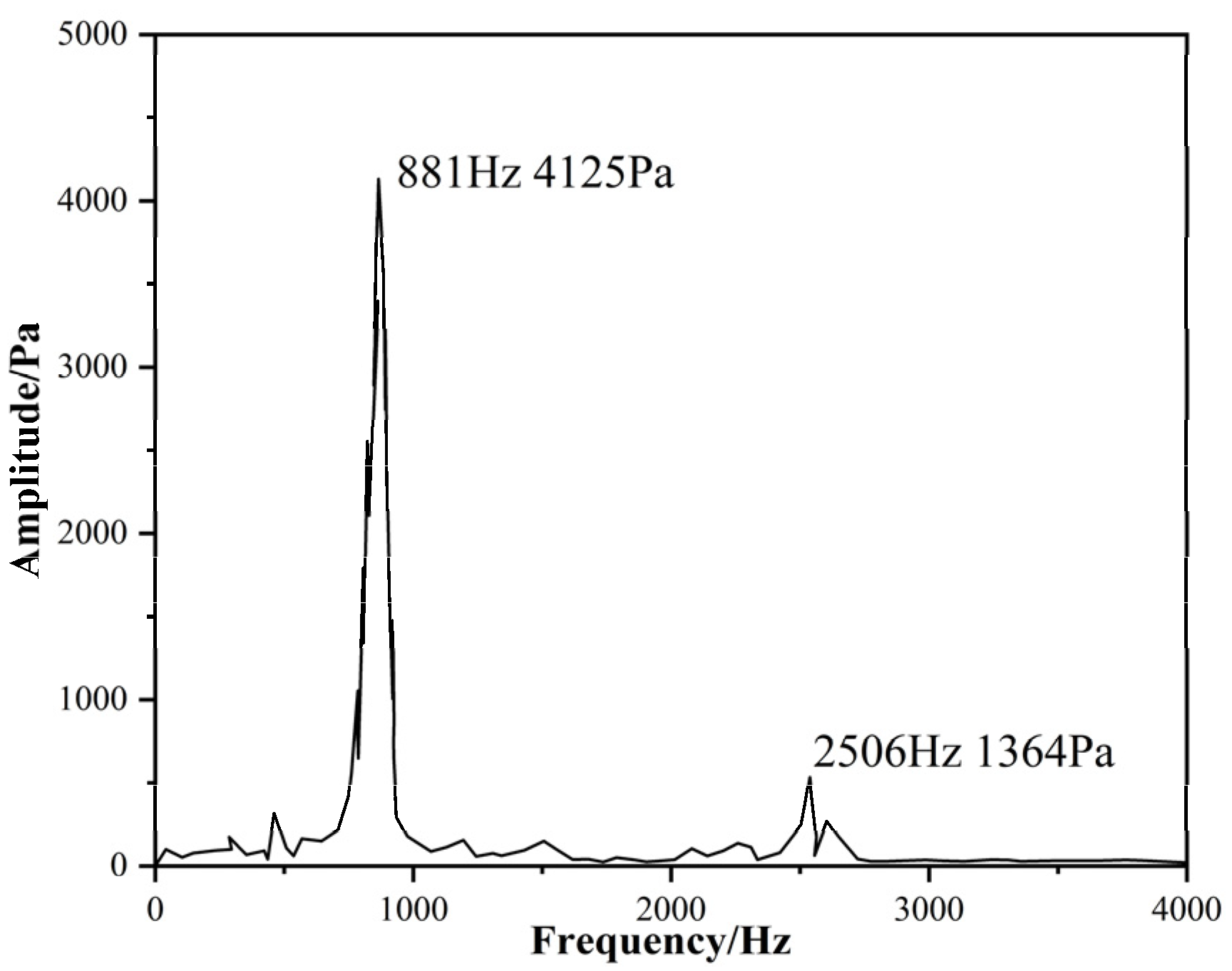
3.2. Verification of the Numerical Method

Based on the grid independence analysis, the simulation was first launched with the 270,000 grid. A comparison with the experimental data was further carried out to verify the numerical methodology based on the LES method under a pure-gas flow condition. The Clx motor was designed to be able to achieve self-excited oscillations.
Figure 3 illustrates pressure oscillations from 0.006 s to 0.082 s in the motor. It can be observed that the pressure oscillates between 3.885 MPa and 3.906 MPa, which is consistent with the values observed in the experiment [38]. Figure 4 shows the FFT spectrum based on the pressure data in Figure 3. The frequencies of the pressure oscillation in the first-order and third-order modes are 881 Hz and 2506 Hz, respectively.
Compared with the experiments, as shown in Table 3, the two main frequencies obtained in the simulations are quite close to those in the experimental data. The biggest difference, 3.57%, occurs when the frequency at the first-order mode is predicted, which is still allowed by the precision requirements. The results show that the numerical methodology established in this study can accurately and effectively predict the characteristics of the engine’s flow field.

4. Numerical Results and Discussion

In order to obtain a clear vortex structure and successfully compare the vortex movements under both pure-gas flow and two-phase flow conditions, the simulations in this section were carried out with a pressure inlet placed at the head of the combustion chamber instead of the side wall.

4.1. Analysis of Key Parameters of the Particle Phase

Focusing on two of the most important parameters, particle diameter and concentration, simulations were carried out of the introduction of aluminum oxide particles to explore their effects on the internal flow and pressure oscillations of the engine. Particle concentration is used below to represent the mass fraction of the particle phase in the total substance.

4.1.1. Particle Diameter

Generally, the particle diameter in the combustion chamber of solid rocket motors ranges between 10 and 100 µm. Therefore, particle diameters of 30 µm and 60 µm were chosen. A 20% particle concentration was applied.
Figure 5 shows the pressure oscillations in the combustion chamber under three different conditions: pure-gas flow; two-phase flow with particles measuring 30 µm; and two-phase flow with particles measuring 60 µm. This indicates that the introduction of a particle phase generally leads to a decrease in both the frequency and amplitude of pressure oscillations. Meanwhile, a larger particle diameter leads to lower amplitude pressure oscillations. Both the amplitude and frequency were significantly reduced for particles measuring 60 µm. Overall, an increase in particle diameter results in a decrease in both the frequency and the amplitude of the pressure oscillations at a constant particle concentration.
Figure 6 illustrates the internal flow near the backward step under the three different conditions at the time t = 1.57 ms. From Figure 6a, it can be seen that the flow instability in the upstream of the step leads to continuous vortices at the step corner in the pure-gas flow; when introducing 30 µm particles into the flow, the vortex structure and distribution behind the step are essentially identical to those in pure-gas flow (Figure 6b), except that the vortex scale becomes slightly larger. Meanwhile, a small but visible disturbance emerges in the downstream flow field: when the particle size increases to 60 µm, a complete vortex structure at the step corner is no longer observed (Figure 6c). Instead, multiple small-scale vortices form. Additionally, the vortex structure and distribution become disordered, and it becomes difficult to distinguish the boundary of the vortex. In summary, it is evident that an increase in particle diameter leads to a greater disturbance in vortex shedding and more serious instability in the shear layer around the step corner. For a more favorable vortex structure, a particle diameter of 30 µm is chosen for subsequent simulations.

4.1.2. Particle Concentration

With the particle size set to 30 µm, several particle mass concentrations of aluminum oxide (0, 20%, and 40% (the proportion of particle mass over total mass)) were chosen to explore their effect on the flow. A concentration of zero corresponds to the pure-gas flow. Although particle mass concentrations can be up to 40%, volumetric concentrations are all much smaller than 10%. That is also the reason why the DPM model was applied in this study.
Figure 7 shows pressure oscillations in the combustion chamber under different conditions: pure-gas flow and two-phase flow with particle concentrations of 20% and 40%. From Figure 5 and Figure 7, it can be concluded that compared with the particle diameter, the particle concentration has more significant effects on pressure oscillations. Meanwhile, Figure 7 indicates that introducing particles with a certain concentration decreases both the frequency and amplitude of pressure oscillations. As the particle concentration increases, the primary frequency of pressure oscillations gradually decreases; meanwhile, the amplitude of pressure oscillation significantly decreases.
Figure 8 illustrates the vorticity distribution for one period in pure-gas flow. An obvious flow separation occurs near the boundary layer in the upstream of the step due to the large aspect ratio, and a complete vortex structure can be observed at the step corner. From Figure 8, it can be seen that a vortex initially emerges in an unstable shear layer, passing through the corner and flowing counterclockwise towards the downstream. At t1 + 1/2Δt1, the small vortices near the corner gradually grow larger and tend to separate; the vortex subsequently develops and moves toward the nozzle. The presence of a corner in the nozzle-convergent section causes the upstream vortex to split and form a new vortex, and some vortices collide with the nozzle wall and break. The vortex structure and motion are clearly visible in pure-gas flow, allowing for the observation of interactions between the vortex and the wall. The period of vortex shedding is approximately 0.92 ms, and the corresponding frequency is 1081 Hz.
Figure 9 presents the vorticity distribution in two-phase flow with different particle concentrations. It can be observed that when adding 20% particles, a vortex can still develop, but there is a noticeable disturbance. The particles disrupt the shear layer near the wall, which results in increased turbulence intensity and dissipation of the large-scale vortex. Compared with the pure-gas flow, the vortex structure in two-phase flow becomes distorted, although it remains visible and recognizable. Compared with a 20% particle concentration, the vortex scale at a 40% particle concentration is significantly decreased. The vortex structure at the corner and downstream becomes more chaotic. Those phenomena hinder the formation of well-organized vortices.
In summary, in order to successfully obtain the internal pressure oscillation and vortex–acoustic coupling of the motor under two-phase conditions, aluminum oxide with a particle size of 30 μm and a concentration of 20% was chosen to further explore the effects of the key geometric parameters of the backward step.

4.2. Analysis of Key Geometric Parameters of the Backward Step

Based on the computational results above, this section aims to explore the effects of key parameters such as the downstream aspect ratio, the expansion ratio, and the step position. Large eddy simulations were applied to numerically analyze both pure-gas and two-phase flows. By comparing the pure-gas flow, insights into the effects of backward geometric parameters on corner vortex motion, acoustic vortex coupling phenomena, and pressure oscillations under the two-phase flow interactions were obtained.

4.2.1. Upstream Aspect Ratio of the Step

Using the Clx as a reference and maintaining the downstream diameter of the step, the expansion ratio, and the upstream length and diameter of the step constant, it was found that the downstream length of the step varies between 150 mm and 300 mm, meaning that the downstream aspect ratio L/D ranges from 1.7 to 3.5. Numerical simulations were carried out to explore the influence of the downstream aspect ratio of the step.
Table 4 presents the vortex shedding frequency, the primary frequency, and the amplitude of the pressure oscillations in the combustion chamber with different downstream aspect ratios for the step under pure-gas and two-phase flow conditions. It demonstrates that the effects of the downstream aspect ratio on vortex shedding and pressure oscillation in two-phase flow are mostly similar to those in the pure-gas flow. As the downstream aspect ratio increases from 1.7 to 3.5, both the frequencies of the vortex shedding and the pressure oscillations decrease by 32.2% and 44.2%, respectively, under the two-phase flow. This occurs because increasing the downstream aspect ratio affects downstream flow development. When the downstream aspect ratio is great, the vortex dissipation gradually increases, which makes it difficult to produce a complete vortex that collides with the nozzle. When the downstream aspect ratio is 1.7, the vortex shedding frequency in the pure gas matches the pressure oscillation frequency. That means that vortex–acoustic coupling is present; under this coupling, the amplitude of pressure oscillations reaches a higher state compared with other cases. However, due to the particles, the effect of vortex–acoustic coupling decreases. This is because the two-phase flow enhances the intensity of turbulence and strengthens the vortex dissipation in the downstream step.
Taking L/D-4.2-1.7 and L/D-4.2-3.5 as examples, in the pure-gas flow, the main frequencies of pressure oscillation at the head of the combustor are 1603 Hz and 862 Hz, respectively. As shown in Figure 10, when the downstream aspect ratio increases, the amplitude of the pressure oscillation for L/D-4.2-3.5 is lower, approximately half of that for L/D-4.2-1.7. Compared to pure-gas flow, the main frequency of the pressure oscillation in two-phase flow can be reduced by up to about 12%. At the same time, the amplitude of the pressure oscillation is also reduced by about 13%.
Figure 11 illustrates the vorticity distribution for the configuration L/D-4.2-3.5 in both pure-gas and two-phase flows. In pure-gas flow, due to the instability of the upstream flow, a vortex forms at the step corner and develops in the downstream step. During its development, the vortex scale increases because of the influence of the main flow. As the vortex moves near the nozzle, it interacts with the vortices produced by the corner at the nozzle-convergent section. They mix partly and form a new relatively big vortex, while the other part flows out with the mainstream. The vortex-shedding period is T = 0.92 ms, corresponding to a frequency of 1081 Hz. In comparison to the pure-gas flow, the vortex motion in two-phase flow follows a similar development trend but exhibits a different scale and structure. Figure 11b shows that the introduction of condensed particles results in a less clear but larger vortex in comparison to that in pure-gas flow. Downstream vortex development is affected by condensate particles, and a series of smaller vortices form. Consequently, the complete large-scale vortex that collides with the nozzle is weakened, and the vortex–acoustic coupling also has less of an effect on the pressure oscillations. The complete vortex-shedding period in two-phase flow is about 1.03 ms, corresponding to a frequency of 997 Hz.

4.2.2. Expansion Ratio

Keeping the downstream diameter and length of the step constant, the expansion ratio of the step varies between 1.1 and 1.4. Numerical simulations were carried out to explore the influence of the expansion ratio.
Table 5 presents the vortex shedding and primary frequencies and the amplitude of the pressure oscillations in the combustion chamber with different expansion ratios under pure-gas and two-phase flow conditions. The results demonstrate that with an increased expansion ratio, both the frequencies of the vortex shedding and those of the pressure oscillation increase globally. As the expansion ratio increases from 1.1 to 1.4, both the frequencies of vortex shedding and pressure oscillation increase by 28.3% and 47%, respectively, in two-phase flow. However, there is no consistent change in the amplitude of pressure oscillations under both pure-gas and two-phase flows. At an expansion ratio of 1.1, the frequency of vortex shedding in pure-gas flow is very close to the primary frequency of pressure oscillations, which means that vortex–acoustic coupling occurs. The effect of vortex–acoustic coupling is weakened due to the inclusion of particles.
Figure 12 and Figure 13 present the distributions of the axial velocity and turbulent viscosity at locations in the downstream step, with an expansion ratio of 1.4. Compared to pure-gas flow, the velocity decreases and the turbulent viscosity increases in two-phase flow. These differences become smaller when the locations are further from the step in the downstream. Through this comparison, it can be concluded that the introduction of particles hinders the development of vortex motion and increases vortex dissipation. It is difficult for the vortex generated by the step to develop stably in the downstream flow process, which reduces the pressure oscillation frequency.

4.2.3. Backward Step Location

At a constant total length of the motor (600 mm) and constant upstream and downstream diameters, the backward step location from the head of the combustion chamber varies from 150 mm to 450 mm. Numerical simulations were carried out to explore the influence of the backward step locations.
Table 6 shows the vortex shedding frequency, the primary frequency, and the amplitude of pressure oscillations in the combustion chamber at different backward step locations under pure-gas and two-phase flows. The results indicate that the overall trends in both the vortex shedding frequency and the pressure oscillations are essentially the same, with the step moving to the downstream in pure-gas and two-phase flows. In general, as the step moves downstream, there is a significant increase in the frequencies of vortex shedding and pressure oscillation. When the step is set in the middle or upstream positions, the vortex shedding frequency is close to the pressure oscillation frequency, which facilitates vortex–acoustic coupling. In the same way as they did in the analysis above, particles decrease the frequency and amplitude of the pressure oscillations.
From the analysis above, it can be concluded that particles primarily influence flow stability in the upstream step and vortex development in the downstream step. Moving the step downstream means the upstream length of the step becomes longer while the downstream length becomes shorter. This facilitates the development of an unstable upstream flow and increases the frequency of the vortex’s interaction with the nozzle. This enables the main pressure oscillation frequency to transition from a fundamental frequency to a higher-order acoustic mode. This analysis is consistent with that presented in Figure 14. It illustrates that when the step moves downstream, the primary frequency of the pressure oscillations changes to a second-order acoustic mode. Meanwhile, it can also be observed that the amplitude of pressure oscillations significantly decreases.

5. Conclusions

Based on the large eddy simulation (LES) method and the discrete phase model (DPM), a numerical methodology for studying vortex–acoustic coupling and pressure oscillations in a solid rocket motor is established in this study. Taking the Clx with a backward step as the reference and introducing aluminum oxide particles, simulations were carried out to explore the motion law of vortex shedding under two-phase flow interactions and the features of pressure oscillations. The main conclusions are summarized here.
(1) A numerical methodology based on LES for pure-gas flow was established. Taking Clx as a reference, grid independence was analyzed, and the numerical methodology was verified. Compared with the results of the experiments, the primary frequency and amplitude of pressure oscillations from simulations have maximum errors of 3.57% and 3.13%, respectively. This indicates that the numerical methodology established in this study can accurately predict the flow field of engines.
(2) Through introducing aluminum oxide particles and applying the DPM model, a numerical methodology to simulate two-phase flow was established. Simulations were carried out to explore the effects of two key particle parameters: particle diameter and concentration. The results indicate that both the primary frequency and the amplitude of pressure oscillations can be decreased by 20% and 35.8%, respectively, with the particle diameter increased to 60 µm. The same trends can be obtained by increasing particle concentration. Compared to particle size, particle concentration has a more pronounced influence on pressure oscillations.
(3) The effects of the key geometric parameters of the backward step, such as the downstream aspect ratio, expansion ratio, and step location, on vortex shedding and pressure oscillations were numerically studied under both pure-gas and two-phase flows. The results indicate that the influence of geometric parameters is basically consistent under two different flow conditions. Overall, the introduction of particles reduces the vortex shedding frequency and the primary pressure oscillation frequency, as well as the amplitude. In general, as the downstream aspect ratio increases from 1.7 to 3.5, both the frequencies of vortex shedding and pressure oscillations can decrease by 32.2% and 44.2%, respectively, under two-phase flow. As the expansion ratio increases from 1.1 to 1.4, the frequency of both vortex shedding and pressure oscillation can increase by 28.3% and 47%, respectively, in two-phase flow, and moving the step to the nozzle can enable the primary frequency of pressure oscillations to transition from a fundamental frequency to a high mode.
The work in this paper mainly focuses on two-phase flow interactions and their effects on pressure oscillations. Since particle motion essentially stems from chemical reactions, it is recommended that future work should utilize single- or muti-step chemical reactions along with particle motions in computations.

Author Contributions

Conceptualization, C.H.; methodology, T.L., H.X., C.H. and J.H.; software, T.L.; validation, T.L. and H.X.; formal analysis, H.X. and C.H.; investigation, H.X. and C.H.; resources, C.H., T.L. and J.H.; data curation, T.L., J.H. and H.X.; writing—original draft preparation, H.X. and C.H.; writing—review and editing, J.H. and C.H.; visualization, J.H. and C.H.; supervision, C.H.; project administration, C.H. All authors have read and agreed to the published version of the manuscript.

Funding

Sponsored by the Practice and Innovation Funds for Graduate Students of Northwestern Polytechnical University (PF2024044).

Data Availability Statement

The data that support the findings of this study are available from the corresponding author upon reasonable request.

Conflicts of Interest

The authors declare no conflicts of interest.

Abbreviations

The following abbreviations are used in this manuscript:
LESlarge eddy simulation
DPMdiscrete phase model
RANSReynolds-averaged Navier–Stokes equation
DNSdirect numerical simulation
SGSsubgrid-scale model
ONERAOffice National d’Etudes et de Recherches
FFTfast Fourier transformation

References

  1. Vacher, D.; Dudeck, M.A.; André, P.; Silva, M.L.D.; Faure, G.E.; Dubois, M.; Hamwi, A.; Menecier, S.; Rochette, D. Radiation from an ICP plasma torth in the near-UV to near-IR spectral region for a Tiran-type N2-CH4 mixture. Tech. Phys. 2009, 50, 213–231. [Google Scholar]
  2. Scippa, S.; Pascal, P.; Zanier, F. Ariane 5-MPS-Chamber Pressure Oscillations Full Scale Firing Results: Analysis and Further Studies. In Proceedings of the 30th Joint Propulsion Conference and Exhibit, Indianapolis, IN, USA, 27–29 June 1994; p. 3068. [Google Scholar]
  3. Zhang, Q.; Wei, Z.; Su, W.; Li, J.; Wang, N. Theoretical modeling and numerical study for thrust-oscillation characteristics in solid rocket motors. J. Propuls. Power 2012, 28, 312–322. [Google Scholar] [CrossRef]
  4. Blomshield, F. Lessons Learned in Solid Rocket Combustion Instability. In Proceedings of the 43rd AIAA/ASME/SAE/ASEE Joint Propulsion Conference & Exhibit, Cincinnati, OH, USA, 8–11 July 2007. [Google Scholar]
  5. Brown, R.; Dunlap, R.; Young, S.; Waugh, R. Vortex shedding as a source of acoustic energy in segmented solid rockets. J. Spacecr. Rocket. 1981, 18, 312–319. [Google Scholar] [CrossRef]
  6. Flatau, A.; VanMoorhem, W. Prediction of vortex shedding responses in segmented solid rocket motors. In Proceedings of the 26th Joint Propulsion Conference, Orlando, FL, USA, 16–18 July 1990; p. 2073. [Google Scholar]
  7. Miao, Q.; Shen, Z.; Zhang, H.; Sun, H. Multiobjective Optimization Method of Solid Rocket Motor Finocyl Grain Based on Surrogate Model. Aerospace 2022, 9, 679. [Google Scholar] [CrossRef]
  8. Hyun, W.; Kim, J.; Chae, H.; Lee, C. Passive Control of Low-Frequency Instability in Hybrid Rocket Combustion. Aerospace 2021, 8, 204. [Google Scholar] [CrossRef]
  9. Flandro, G.; Jacobs, H. Vortex generated sound in cavities. In Proceedings of the Aeroacoustics Conference, Seattle, WA, USA, 15–17 October 1973; p. 1014. [Google Scholar]
  10. Dunlap, R.; Brown, R.S. Exploratory experiments on acoustic oscillations driven by periodic vortex shedding. AIAA J. 1981, 19, 408–409. [Google Scholar] [CrossRef]
  11. Culick, F.E.C.; Yang, V. Prediction of the stability of unsteady motions in solid-propellant rocket motors. Nonsteady Burn. Combust. Stab. Solid Propellants 1992, 143, 719–779. [Google Scholar]
  12. Dotson, K.W.; Koshigoe, S.; Pace, K.K. Vortex Shedding in a Large Solid Rocket Motor Without Inhibitors at the Segment Interfaces. J. Propuls. Power 1997, 13, 197–206. [Google Scholar] [CrossRef]
  13. Apte, S.; Yang, V. Unsteady flow evolution in porous chamber with surface mass injection, part 1: Free oscillation. AIAA J. 2001, 39, 1577–1586. [Google Scholar] [CrossRef]
  14. Apte, S.; Yang, V. Unsteady flow evolution in porous chamber with surface mass injection, part 2: Acoustic excitation. AIAA J. 2002, 40, 244–253. [Google Scholar] [CrossRef]
  15. Cai, W.; Ma, F.; Yang, V. Two-Phase Vorticoacoustic Flow Interactions in Solid-Propellant Rocket Motors. J. Propuls. Power 2003, 19, 385–396. [Google Scholar] [CrossRef]
  16. Chen, L.; Gao, Y.; Wang, D.; Zou, Q.; Zhang, S. Numerical simulation on acoustic mode and pressure-oscillation decay in finocyl-and axil-grain combustion chambers. Aerosp. Sci. Technol. 2020, 107, 106351. [Google Scholar] [CrossRef]
  17. Jalili, B.; Jalili, P. Numerical analysis of airflow turbulence intensity effect on liquid jet trajectory and breakup in two-phase cross flow. Alex. Eng. J. 2023, 68, 577–585. [Google Scholar] [CrossRef]
  18. Zhang, Q.; Wang, N.; Li, J.; Su, W.; Zhang, Y. Effect of the head cavity on pressure oscillation suppression characteristics in large solid rocket motors. Sci. China Technol. Sci. 2015, 58, 1250–1262. [Google Scholar] [CrossRef]
  19. Wang, D.; Yang, Y.; Fan, W.; Li, X.; Gao, Y. Simulation of pressure oscillations in a combustion chamber under periodic inlet disturbances. Acta Astronaut. 2018, 152, 859–871. [Google Scholar] [CrossRef]
  20. Xingpeng, G.; Junwei, L.; Wensheng, Q.; Sheng, W.; Lei, H.; Qi, W.; Ningfei, W. Motion Trajectory of Solid Particles in Clxb Solid Rocket Motor. Acta Armamentarii 2022, 43, 489–502. [Google Scholar]
  21. Huo, C.; Luo, T.; Liu, P. Numerical Simulations of Vortex-Acoustic Coupling in Two-Phase Flow of VKI Motor. In Proceedings of the 2022 13th International Conference on Mechanical and Aerospace Engineering (ICMAE), Bratislava, Slovakia, 20–22 July 2022; IEEE: Piscataway, NJ, USA, 2022; pp. 384–389. [Google Scholar]
  22. Ferretti, V. Numerical simulations of acoustic resonance of Solid Rocket Motor. In Proceedings of the 46th AIAA/ASME/SAE/ASEE Joint Propulsion Conference & Exhibit, Nashville, TN, USA, 25–28 July 2010. [Google Scholar]
  23. Aider, J.-L.; Danet, A. Large-eddy simulation study of upstream boundary conditions influence upon a backward-facing step flow. Comptes Rendus Mécanique 2006, 334, 447–453. [Google Scholar] [CrossRef]
  24. Neto, A.S.; Grand, D.; Metais, O.; Lesieur, M. Large-eddy simulation of the turbulent flow in the downstream region of a backward-facing step. Phys. Rev. Lett. 1991, 66, 2320. [Google Scholar] [CrossRef]
  25. Vuillot, F. Vortex-shedding phenomena in solid rocket motors. J. Propuls. Power 1995, 11, 626–639. [Google Scholar] [CrossRef]
  26. Ruifeng, T.; Pingan, L. Numerical Calculation of Heat Transfer and Fluid Flow; Harbin Engineering University Press: Harbin, China, 2015. [Google Scholar]
  27. Smagorinsky, J. General circulation experiments with the primitive equations: I. The basic experiment. Mon. Weather. Rev. 1963, 91, 99–164. [Google Scholar] [CrossRef]
  28. Nicoud, F.; Ducros, F. Subgrid-scale stress modelling based on the square of the velocity gradient tensor. Flow Turbul. Combust. 1999, 62, 183–200. [Google Scholar] [CrossRef]
  29. Zahari, N.; Zawawi, M.; Sidek, L.; Mohamad, D.; Itam, Z.; Ramli, M.; Syamsir, A.; Abas, A.; Rashid, M. Introduction of discrete phase model (DPM) in fluid flow: A review. In Proceedings of the AIP Conference Proceedings, Ho Chi Minh, Vietnam, 29–30 April 2018. [Google Scholar]
  30. Wu, H.; Liu, T.; Yang, Y. Simulation of Particle Trajectory in T-shaped Pipes Based on the DPM Model. Sci. Technol. 2021, 17, 21–22. [Google Scholar]
  31. Kuipers, J.A.M.; van Duin, K.J.; van Beckum, F.P.H.; van Swaaij, W.P.M. A Numerical Model of Gas-fluidzed Beds. Chem. Eng. Sci. 1992, 47, 1913–1924. [Google Scholar] [CrossRef]
  32. Ergun, S. Fluid Flow through Packed Columns. Chem. Eng. Prog 1952, 48, 89–94. [Google Scholar]
  33. Wen, C.Y.; Yu, Y.H. Mechanics of Fluidization. Chem. Eng. Prog. Symp. Ser 1966, 162, 100–111. [Google Scholar]
  34. Lupoglazoff, N.; Vuillot, F. Numerical simulation of vortex shedding phenomenon in 2D test case solid rocket motors. In Proceedings of the 30th Aerospace Sciences Meeting and Exhibit, Reno, NV, USA, 6–9 January 1992; p. 776. [Google Scholar]
  35. Patankar, S.V.; Spalding, D.B. Paper 5—A calculation proceduce for heat, mass and momentum transfer in three-dimensional parabolic flows. In Numerical Prediction of Flow, Heat Transfer, Turbulence and Combustion; Pergamon: Bergama, Turkey, 1983; pp. 54–73. [Google Scholar]
  36. Lupoglazoff, N.; Vuillot, F. Comparison between firing tests and numerical simulation of vortex shedding in a 2-D test solid motor. In Proceedings of the 23rd Fluid Dynamics, Plasmadynamics, and Lasers Conference, Orlando, FL, USA, 6–9 July 1993; p. 3066. [Google Scholar]
  37. Flatau, A.; Moorhem, W. Cold-flow investigation of vortex-shedding induced sound amplitude variations. In Proceedings of the 33rd Aerospace Sciences Meeting and Exhibit, Reno, NV, USA, 9–12 January 1995; p. 605. [Google Scholar]
  38. Zhang, X.Y.; He, G.Q.; Liu, P.J. Classification of corner vortex shedding in soild rocket motor. J. Aerosp. Power 2014, 29, 2003–2011. [Google Scholar]
Figure 1. Configurations of Clx motor.
Aerospace 11 01054 g001
Figure 2. Local meshes around the backward step: (a) 520,000; (b) 270,000; (c) 140,000.
Aerospace 11 01054 g002
Figure 3. Pressure oscillations.
Aerospace 11 01054 g003
Figure 4. Pressure oscillation spectrum at point head.
Aerospace 11 01054 g004
Figure 5. Pressure oscillations with different particle sizes.
Aerospace 11 01054 g005
Figure 6. Vorticity distribution at t = 1.57 ms under different cases: (a) pure gas; (b) 30 μm; (c) 60 μm.
Aerospace 11 01054 g006
Figure 7. Pressure oscillations with different particle concentrations.
Aerospace 11 01054 g007
Figure 8. Vorticity distribution of one period in pure-gas flow.
Aerospace 11 01054 g008
Figure 9. Vorticity distribution with different particle concentrations: (a) 20%; (b) 40%.
Aerospace 11 01054 g009
Figure 10. Pressure oscillations with different downstream aspect ratios: (a) L/D-4.2-1.7; (b) L/D-4.2-3.5.
Aerospace 11 01054 g010
Figure 11. Vorticity distributions in pure-gas and two-phase flows for L/D-4.2-3.5: (a) pure gas; (b) two-phase.
Aerospace 11 01054 g011
Figure 12. Velocity distribution in cross-sections at different positions: (a) x1 = 0.19 m; (b) x2 = 0.20 m.
Aerospace 11 01054 g012
Figure 13. Turbulent viscosity distribution in cross-sections at different positions: (a) x1 = 0.19 m; (b) x2 = 0.20 m.
Aerospace 11 01054 g013
Figure 14. Pressure oscillations under different step locations in two-phase flow: (a) L/D-2.5-4; (b) L/D-5-3.
Aerospace 11 01054 g014
Table 1. Clx engine dimensions.
PartSize
Upstream length of the step a350 mm
Downstream length of the step b350 mm
Nozzle length c50 mm
The angle of backward step α135°
Table 2. Numerical results at different grid scales.
Total ElementsAmplitude (Pa)Frequency (Hz)
520,0004107879.40
270,0004125881.74
140,0004248784.15
Table 3. Comparisons between CFD and experiments.
ModeParameterSimulationExperiment Error
1Frequency of pressure oscillation/Hz8818503.57%
Amplitude of pressure oscillation/Pa412542543.13%
3Frequency of pressure oscillation/Hz250625401.32%
Amplitude of pressure oscillation/Pa136413282.74%
Table 4. Vortex shedding and pressure oscillations with changed upstream aspect ratio.
CaseVortex Shedding
Frequency (Hz)
Pressure Oscillation
Frequency (Hz)
Pressure Oscillation
Amplitude (‰)
Pure-Gas FlowTwo-Phase FlowPure-Gas FlowTwo-Phase FlowPure-Gas FlowTwo-Phase Flow
L/D-4.2-1.716761471160314060.590.54
L/D-4.2-2.315571404132712240.430.41
L/D-4.2-31296119210129510.320.29
L/D-4.2-3.510819978627840.310.27
Table 5. Vortex shedding and pressure oscillation with changed expansion ratio.
Expansion RatioVortex Shedding
Frequency (Hz)
Pressure Oscillation
Frequency (Hz)
Pressure Oscillation Amplitude (‰)
Pure-Gas FlowTwo-Phase FlowPure-Gas FlowTwo-Phase FlowPure-Gas FlowTwo-Phase Flow
1.41050955152813860.410.38
1.3870791122411650.520.48
1.27767069799330.610.57
1.17536857827340.570.55
Table 6. Vortex shedding and pressure oscillation with changed backward step locations.
CaseUpstream and
Downstream Length Ratio
of the Step
Vortex Shedding
Frequency (Hz)
Pressure Oscillation
Frequency (Hz)
Pressure Oscillation
Amplitude (‰)
Pure-Gas FlowTwo-Phase FlowPure-Gas FlowTwo-Phase FlowPure-Gas FlowTwo-Phase Flow
L/D-2-51/36516148717830.420.40
L/D-2.8-4.71/26936439268330.310.29
L/D-2.5-45/77537078807920.630.59
L/D-4.2-3.51/110819978627840.290.28
L/D-5-37/512251151168415120.330.32
L/D-6.4-1.73/112561192172815450.150.15
Disclaimer/Publisher’s Note: The statements, opinions and data contained in all publications are solely those of the individual author(s) and contributor(s) and not of MDPI and/or the editor(s). MDPI and/or the editor(s) disclaim responsibility for any injury to people or property resulting from any ideas, methods, instructions or products referred to in the content.

