1. Introduction
With the development of the economy and technology, unmanned aerial vehicles (UAVs) are widely applied in today’s society. In the civilian sector, the continuous advancement of low-altitude airspace opening reforms in China has led to an increasing number of UAVs being utilized in power line patrol, express delivery, geological survey, and other fields, greatly promoting economic development. In the military sector, UAVs undertake reconnaissance, strike, and transportation tasks in contemporary local conflicts around the world and are favored by the military due to their low cost and versatility. With the continuous expansion of UAV applications, more UAVs will fly into the skies, while airspace resources are limited. A stable, accurate, and efficient method for UAV conflict detection and resolution is key to ensuring the safe and efficient operation of large numbers of UAVs within limited airspace [
1].
The method for detecting UAV flight conflicts in three-dimensional space is primarily based on the Euclidean formula to determine the distance between two UAVs, with the calculation formula as follows:
where
and
are the coordinates of two UAVs at a given moment. If the distance is greater than the safety interval, it indicates no conflict; if less, it indicates a conflict between UAVs. By calculating the distances between all pairs of UAVs, the detection of UAV conflicts within the airspace is achieved. When there are many UAVs, using the Euclidean formula requires a large number of calculations to detect all conflicts, which has the disadvantages of large computational volume and high computational complexity. Therefore, scholars at home and abroad have conducted in-depth research on improved UAV conflict detection methods. Bilimoria [
2], focusing on the conflict detection problem of aircraft within a two-dimensional plane, derived an analytical solution based on the geometric characteristics of flight trajectories and achieved conflict resolution by adjusting speed and heading. Dang Shan [
3], based on the study of various UAV conflict detection algorithms, comprehensively considered the position accuracy in ADS-B (Automatic Dependent Surveillance–Broadcast) messages, described the credibility of parameters through navigation accuracy and integrity levels, compensated the time of the closest point with safety margins, and then improved the accuracy of the algorithm for UAV flight conflict detection. In order to adapt to different airspace conditions, Yang Yue et al. [
4] proposed a three-factor repeated measurement experimental scheme. This scheme optimizes the overall performance of the system by adjusting the minimum distance (MD), convergence angle (CA), and speed characteristics (SC) parameters to achieve shorter reaction times and higher accuracy rates. The results of this research are of great reference significance for enhancing the perception and prediction capabilities of conflict detection. Jones et al. [
5] introduced polynomial chaos to estimate collision probabilities, used polynomial chaos expansion to approximate the solution of stochastic differential equations, and simulated collision probabilities through the Monte Carlo method to achieve conflict detection.
In terms of UAV conflict resolution, researchers have also conducted extensive and thorough research. Yao Cheng et al. [
6] used genetic algorithms to quickly and effectively determine the optimal conflict resolution path by changing flight headings to achieve the goal of conflict resolution. Zhang Honghong et al. [
7] proposed a concept based on the “core solution” of cooperative game theory, which ensures the fairness of UAV conflict resolution and uses a hybrid solution strategy based on artificial potential field ant colony methods to quickly generate UAV conflict resolution paths. Dong Huyi [
8] applied the sparrow search algorithm to UAV conflict resolution and enhanced the global search capability of the optimization algorithm through improvement, which accelerated the convergence speed in the later stage. Aiming at the shortcomings of genetic algorithms such as slow solution speed and large delay distance when solving UAV conflicts, Zhen Ran et al. [
9] proposed a UAV conflict resolution method based on quantum genetic algorithms. Using quantum rotation gates to achieve individual evolution, the speed of conflict resolution is faster, and the quality of the solution is higher, which improves the effectiveness of conflict resolution. Jie Dong et al. [
10] improved the ant colony algorithm by introducing angle information and sorting systems to enhance its ability to find the optimal conflict resolution path. The results show that the improved ant colony algorithm can effectively provide joint resolution paths for multi-aircraft conflict situations in the airspace. In terms of multi-aircraft conflict issues, Liu et al. [
11] modeled multi-level conflict problems as optimal control problems and used hybrid nonlinear programming methods to solve optimization problems. Based on the optimal solutions obtained, conflict resolution and trajectory recovery are achieved through three changes of speed and heading angle. Wu et al. [
12] took aircraft as nodes, established a flight conflict network based on flight conflict relationships, defined the concept of an optimal dominating set, and quickly resolved conflicts in the network by removing the optimal dominating set nodes of the flight conflict network, which reduced the complexity of the network.
Analyzing the aforementioned literature, current UAV flight conflict detection methods are mostly aimed at two-dimensional planes, and in the case of a large number of UAVs and numerous conflicts, there are still shortcomings such as large computation and low detection efficiency. These methods are difficult to adapt to the future requirements of rapid and accurate determination of conflicts for a high-volume of UAVs in the airspace. In terms of conflict resolution, methods in the literature use geometric positions to optimize future trajectories, which have the disadvantages of long computation time and low success rate in resolving complex conflict scenarios. Meanwhile, some other methods in the literature use traditional intelligent algorithms to transform conflict resolution into an optimization problem, which has the disadvantages of slow convergence speed and insufficient research on continuous resolution problems.
This paper establishes UAV protection zone models and airspace rasterization models, extracts real-time position tensors of operating UAVs, performs tensor operations, and uses the properties of prime factorization to detect flight conflicts in real-time and quickly during UAV flight. After a flight conflict occurs with a UAV, conflict sets are extracted, and the differential algorithm, which is simple, practical, and has strong reliability, efficiency, and robustness, is fully utilized. Further hybrid improvements are made to the differential algorithm, and a differential evolution algorithm with adaptive mutation operators and related mechanisms is designed for conflict resolution. Finally, simulation experiments are conducted to verify the reliability and efficiency of the aforementioned methods for conflict detection and resolution between UAVs in local airspace.
2. UAV Conflict Detection Method Based on Tensor Hadamard Product Operation
2.1. Establishment of UAV Protection Zone and Airspace Grid Model
In the future, UAVs will be used in large quantities across various industries. It is particularly important to avoid collisions between large numbers of UAVs in real time to reduce the risk of UAV collision. And it is the key task for UAV collision avoidance to designate protection zones for UAVs to prevent other UAVs from entering a protected area and to prevent overlapping with other UAVs’ protection zones. The style and size of the UAV protection zone affects the capacity and operational efficiency of UAVs in the airspace. Current methods for modeling UAV protection zones include the Reich cuboid model, the cylindrical protection zone model, the spherical protection zone model, and the ellipsoidal protection zone model [
13]. During flight, UAVs are affected by factors such as wind and positioning accuracy. Analysis using the Monte Carlo method shows that UAVs maintain higher precision in altitude than along the flight path, and a certain safety margin should be retained as the safety interval of UAVs. Therefore, this paper adopts the cylindrical protection zone model and sets up a two-tier collision avoidance strategy: the outer cylindrical protection zone serves as a conflict warning area, which is an unsafe area for timely adjustment and resolution of UAV conflicts; the inner cylindrical area is the core protection zone, which is strictly off-limits.
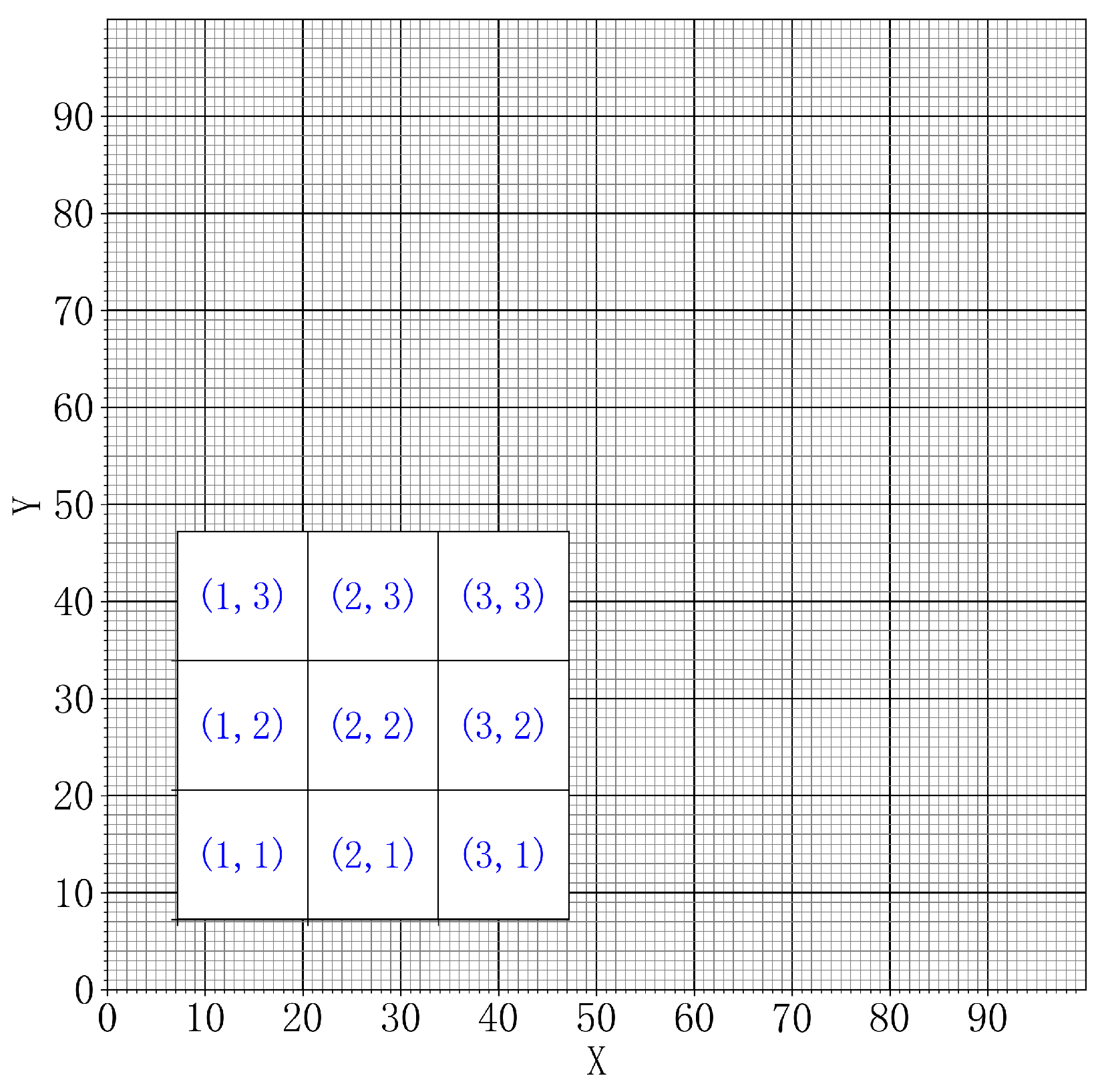
In local warfare, especially in urban combat, the battlefield area is limited, and small and medium-sized UAVs are also limited by range and scope of control, so the effective combat radius of UAVs will be relatively small. This paper simulates an urban combat environment, setting the battlefield airspace to a square area of 10 km × 10 km. Due to the limited battlefield airspace, it is less affected by the curvature of the Earth during the division process. To facilitate coding, this paper divides the grid based on the latitude and longitude coordinate system and controls the precision and calculation speed of conflict detection by setting the granularity of the division [
14]. After dividing into small grids, the grid is encoded in the same way as the plane rectangular coordinate system, with the format
, where
represents the horizontal coordinate of the sub-grid and
represents the vertical coordinate. The grid division result and encoding representation are shown in
Figure 1, in which the 10 km × 10 km airspace is dissected into 100 × 100 sub-grids of 100 m × 100 m.
Based on the cylindrical UAV protection zone model and the airspace rasterization subdivision model, the protection zones of UAVs in the three-dimensional operational airspace are shown in
Figure 2.
2.2. Basic Concepts of Tensors and Hadamard Product Operation
To address the insufficiency of detecting only two-dimensional plane position conflicts using matrix Hadamard product operations and the inability to detect height conflicts, the concept of tensors in physics is introduced [
15]. By utilizing tensor operations, three-dimensional conflict detection for UAVs is realized.
Set , if R, among them ; , then is said to be an n-dimensional real tensor of order m with elements, and is recorded as , notated in particular as . To take the third-order tensor as an example, it is common to use or to represent the elements of the third-order tensor in the i-th row, j-th column, and k-th frontal slice.
Set
,
, denoted as
, where in
,
is
and
’s Hadamard product, which can be noted as
. The Hadamard product can only be performed between tensors when their orders and dimensions are the same [
16].
In this tensor, the order represents the altitude layer of the UAV, and the matrix within the tensor represents the UAV’s position in the two-dimensional plane. Tensor and tensor analysis operations are widely used in the study of continuum mechanics, elasticity, fluid dynamics, electromagnetism, and other fields. Similarly, we can apply them to the field of UAV flight conflict detection to reduce computational volume and the complexity of the detection method.
2.3. 0–1 Tensor Rapid Detection Method
For the spatial position of UAVs, which consists of horizontal, longitudinal, and altitude components, a third-order tensor can represent the spatial position of a UAV. Since the interval between UAVs in the horizontal and longitudinal directions is greater than the interval in altitude, and considering UAVs operate at low altitudes with a much larger range than their ceiling limit, the grid division granularity in the horizontal and longitudinal directions is finer with more dimensions set, whereas the granularity in altitude is coarser with fewer dimensions set. To facilitate calculations, the horizontal and longitudinal coordinates are considered the first and second orders of the tensor, with altitude as the third order. In the tensor center, represents the dimension of the UAV on the horizontal coordinates, represents the dimension of the UAV on the vertical coordinates, and represents the height dimension of the UAV.
In conflict detection using the Hadamard product of tensors, there are two methods: the 0–1 tensor rapid detection method and the detection method based on prime factorization. In the 0–1 tensor rapid detection method, based on gridded airspace, the sub-grid spaces occupied by the UAV and its outer cylindrical protection area are assigned a value of “1”, while other unoccupied positions are assigned a value of “0”. After the assignment is completed, the spatial grid assignment situation of the UAV is extracted as a tensor , which represents the spatial position of the UAV. Similarly, the spatial position tensors of all UAVs are extracted sequentially, and the spatial position tensor of the nth UAV is represented as .
An addition operation is performed on the spatial position tensor of all drones to obtain the sum tensor . The elements in the sum tensor are then analyzed; if there are elements in the sum tensor , it indicates that there are drone conflicts in this airspace, and the conflict position is sliced in row , column , and layer . If all elements in the sum tensor are not greater than 1, it indicates that there are no conflicts. No matter how many UAVs there are, the 0–1 rapid detection method can find out the conflict of the UAV in space with only one calculation, which has the characteristics of speed, efficiency, and accuracy. However, this method also has shortcomings. The use of this method can only detect the location and height of the conflict, and it cannot detect which UAVs are in conflict with each other.
2.4. Flight Conflict Detection Based on Prime Factorization
To improve the shortcomings of the 0–1 detection method, which cannot identify the UAVs involved in conflicts, and to facilitate conflict resolution, the concept of prime numbers and their properties from number theory are introduced to uniquely represent UAVs [
17]. During model establishment, following the 0–1 rapid detection method, a third-order tensor
is used to represent the spatial position of UAVs,
represents the dimension of the UAV on the horizontal coordinates,
represents the dimension of the UAV on the vertical coordinates,
represents the height dimension of the UAV. First, a prime sequence
is established, and each UAV is assigned a prime number that uniquely identifies it. For example, the prime number “2” is used to uniquely identify a UAV
. After the airspace rasterization division, the grid spaces occupied by the UAV
in space are all assigned the value “2”, while unoccupied grids are assigned “1”. After the assignment is completed, the spatial grid assignment situation of the UAV
is extracted as a tensor
, representing the spatial position of the UAV
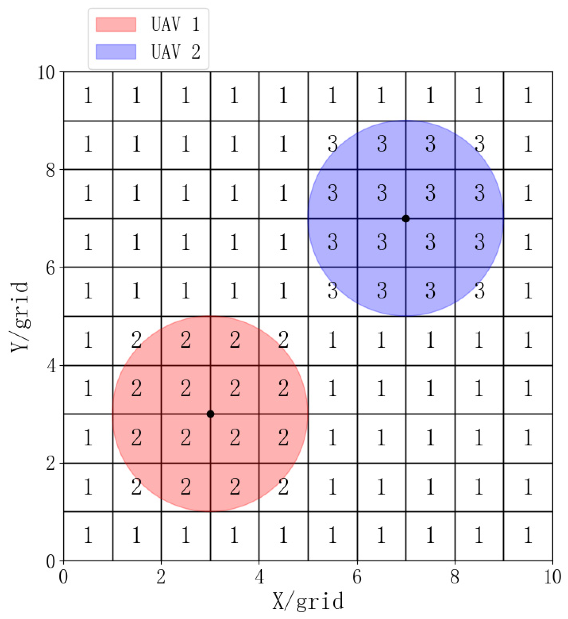
. Similarly, the spatial position tensors of each UAV are extracted in the same manner. The spatial position tensor of the
th UAV
is represented as
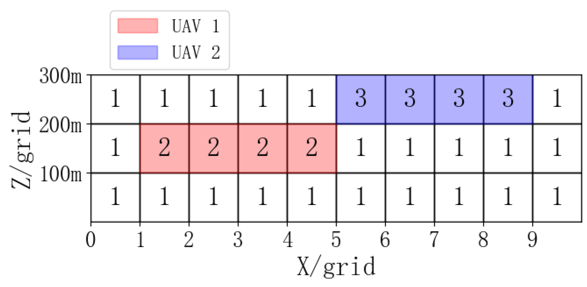
. The front and side projections of the grid assignment situation within the battlefield airspace for UAVs are shown in
Figure 3 and
Figure 4, where the position of the purple UAV is (7, 7, 300), and the red UAV is (3, 3, 200), with the protection zones of both UAVs assigned their corresponding prime numbers.
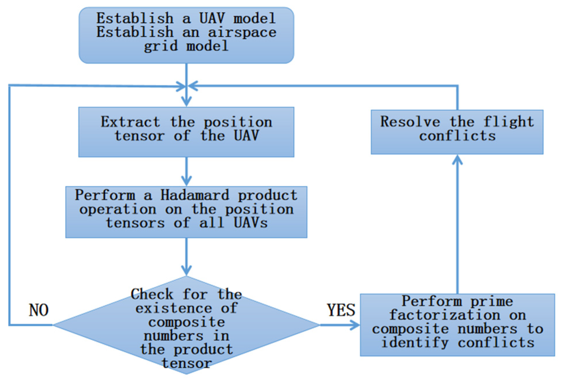
The Hadamard product operation is performed on the spatial position tensors of all UAVs to derive the product tensor, and the elements in the product tensor
are analyzed. If each element is not a composite number, then it means that there is no conflict. If an element
is a composite number, it indicates that there is UAV conflict in this airspace, and the conflict position is sliced in row
, column
, and layer
. A prime factorization of these composite numbers can be decomposed into several prime numbers, thus indicating that there are flight conflicts between the UAVs identified by these prime numbers. The process of flight conflict detection method based on prime factorization is shown in
Figure 5.
On the basis of prime factorization, the flight conflict detection method assigns a prime number to each UAV, uses the Hadamard product operation of tensors to detect the number and location of UAV conflicts, and identifies the UAVs involved in each conflict through the prime factorization method. For large volumes of UAV conflicts within the airspace, this method only requires one tensor calculation and analysis of the conflict set to determine detailed conflict information, greatly reducing the computational effort and shortening the detection time.
3. Flight Conflict Resolution Method Based on Hybrid Improved Differential Evolution Algorithm
3.1. Model Establishment
It is assumed that there are UAVs in operation in a certain altitude layer. Through methods based on matrix or tensor Hadamard products and prime factorization, flight conflicts are detected, with each conflict forming a conflict set. Considering that UAVs need to perform tasks such as reconnaissance and strikes at specific altitude levels, conflict resolution is achieved by adjusting the heading and speed of the conflicting UAVs without considering the change of operating altitude of the UAVs for the time being. To prevent large bank turns when UAVs change course, the range of heading change is limited to around the original flight path, and the range of speed change is limited to . After extracting the conflict set, the heading and speed adjustments for the UAVs within the conflict set are calculated using the hybrid improved differential algorithm. These adjustments are then applied to update the positions of the aircraft and simulate the trajectory of the aircraft for a period in the future. The fitness function is used to perform a conflict assessment of the UAV’s future position. After the assessment, the state of the UAV is restored to the state before the application of the solution, so that the next set of adjustments can be assessed. Ultimately, the heading and speed adjustment plan with the highest fitness is applied to the current aircraft to resolve the flight conflict.
Determination of the objective function and constraints:
Objective function: Setting up an index collection of a conflict aircraft
, there are a number of conflicting UAVs, then the objective of the optimization is set to minimize the distance between any two UAVs in the conflict set, and the target function is
is a set of optimized variables, is the heading change angle of the -th UAV, and is the amount of change in velocity of the -th UAV. represents the Euclidean distance between UAV and UAV. belongs to all conflict UAV coordinates. belongs to all conflict UAV coordinates.
Fitness function: The minimum distance between conflict aircraft is taken as the fitness score. The smaller the distance, the greater the conflict risk and the lower the fitness score. Conversely, the larger the distance, the smaller the conflict risk and the higher the fitness score. The goal of the fitness score assessment is to maximize the minimum distance between conflict aircraft, thus the fitness function is
Speed constraint condition: The speed change of each UAV must satisfy the lower and upper limit constraints: . This constraint ensures that the UAV’s velocity change is always within a reasonable range.
Heading angle constraint condition: The heading change of each UAV also needs to satisfy the lower and upper limit constraints: .
After using the improved differential evolution algorithm to resolve conflicts for UAVs, the criteria for successful resolution are: (1) The UAV can achieve no conflicts in the outer protection zone within 15 s. (2) The UAV can never have a conflict in the inner protection zones during the conflict process. The effectiveness of the improved differential evolution algorithm for UAV conflict resolution is assessed using the above evaluation method.
3.2. Improved Differential Evolution Algorithm with Hybrid Strategy
3.2.1. Differential Evolution Algorithm
A differential evolution (DE) algorithm can reduce the complexity of evolutionary operations by employing real-number encoding and simple differential-based mutation operations, along with one-on-one competitive survival strategies. This unique evolutionary mechanism endows it with strong robustness and global search capabilities, which is a great advantage in solving optimal problems within complex environments [
18].
Initialization: Utilizing
(
is the population size)
-dimensional real-number parameter value vectors, these vectors are used as the population for each generation, with each individual represented as
, where
represents the sequence of the individual within the population and
represents the number of evolutionary generations, which remains constant during the minimization process. The initial population is formed by randomly selecting from the values within the given boundary constraints, which follows a uniform probability distribution. If the parameter boundaries are set as
, then
where
is a uniformly distributed random number between 0 and 1.
Mutation: The mutation operator adopts the best solution plus the differential of random vectors; that is, excluding the current individual in the population, two different individuals are randomly selected for vector differentiation. The result is multiplied by the amplification factor and added to the best individual of the current population, which can accelerate the search for the best solution. The offspring are produced by the following formula:
where
is the best individual in the current population and
are two randomly selected different individuals excluding the current individual.
Crossover: In order to increase the diversity of the interference parameter vectors, the parent individual
and the new individual
produced after the differential mutation operation undergo the following crossover operation:
Let be the value of the -th gene of the -th individual, where , , represents a uniformly distributed random number for the -th gene of the -th individual, and is the introduced random gene position. It is enforced that the gene at the position is taken from the newly mutated individual, making , not completely identical, thus increasing the diversity of the population.
Selection: A greedy selection operator is used to compare the adaptability between the individual
and the original vector
. Only when the adaptability of
is higher than
can it be chosen as the parent of the next generation. Otherwise,
will still be selected as the next generation parent.
Boundary handling: During the mutation operation, the increase in the number of iterations may cause the mutated values to exceed the range of the UAV heading and speed changes. Therefore, if a new individual does not meet the boundary constraints, it will be replaced by a parameter vector randomly generated within the feasible domain, i.e.,
or
, then
Encoding method of differential evolution algorithm: The encoding scheme represents the structure of the solution and the representation of individuals in the population. In this algorithm, each individual is encoded by using a real-number array, with each individual representing a combination of heading and speed adjustments for a group of UAVs. The real-number array of an individual is represented as a chromosome, which contains multiple genes, each representing a specific design variable. In this method, the individual structure is specifically manifested as follows: assuming there are UAVs in the conflict set, then the chromosome of each individual can be represented as , where represents the heading change angle of the -th UAV (in degrees) and represents the speed change amount of the -th UAV. Real-number encoding can directly represent design variables, which has the advantage of high computational efficiency and high precision for solving complex optimization problems containing a large number of continuous variables.
3.2.2. Adaptive Adjustment of Mutation and Crossover Operators
The traditional DE algorithm has difficulty determining the mutation operator. In the calculation, if the mutation rate is set too low, it will reduce the diversity of the population, which will lead to premature convergence. If the mutation rate is set too high, it will reduce the search efficiency and affect the accuracy of the global optimal solution. Therefore, an adaptive mechanism is introduced to automatically adjust parameters and improve algorithm performance [
19].
The adaptive mutation operator is designed as follows:
where
is the mutation operator,
is the maximum number of evolution generations, and G is the current number of evolution generations. This design ensures that the algorithm starts with a larger mutation operator of 2
, which maintains individual diversity and avoids premature convergence. As iterations continue, the mutation operator gradually decreases, preventing the loss of the optimal solution and increasing the probability of finding the global optimal solution.
In addition, considering that the possible random changes during the amplification of the differential vector may help maintain population diversity during the search process, the crossover operator is adaptively adjusted as follows:
where
is a pre-set adjustment factor used to control the adjustment range.
3.2.3. Introduction of Redundant Evaluation Mechanism
The redundant evaluation mechanism is used to improve the accuracy of the evaluation by repeatedly evaluating the target function of each individual to reduce the noise impact in the target function value. The target function of the individual is
, and this function has random noise.
, that is,
.
is the real target function value of the individual
, and
is the Gaussian noise with mean value 0 and variance
. As for the redundant assessment mechanism, the mean value
of
evaluations for individual
is defined as
Each is dependent on which contains the evaluation values of noise. According to the law of large numbers, when , ; that is to say, the real target function value can be approached.
By increasing the number of evaluations
, the impact of noise can be reduced and the accuracy of the estimation can be improved. The estimated variance is
Therefore, the redundant evaluation mechanism reduces the variance by increasing , making closer to .
3.2.4. Confidence Level-Based Selection Strategy
A selection strategy based on the level of confidence takes into account the uncertainty (e.g., variance) of individual evaluation to determine confidence in a solution, and then introduces uncertainty information into the process of individual selection. It is assumed that
redundancy assessments for individuals
is performed to obtain the assessment mean value
and standard deviation
. A confidence interval can be calculated to judge the quality and stability of the solution. The range of confidence intervals can be determined by the sample mean and standard deviation:
When
is the critical value under the normal distribution, for the width of 95% confidence interval,
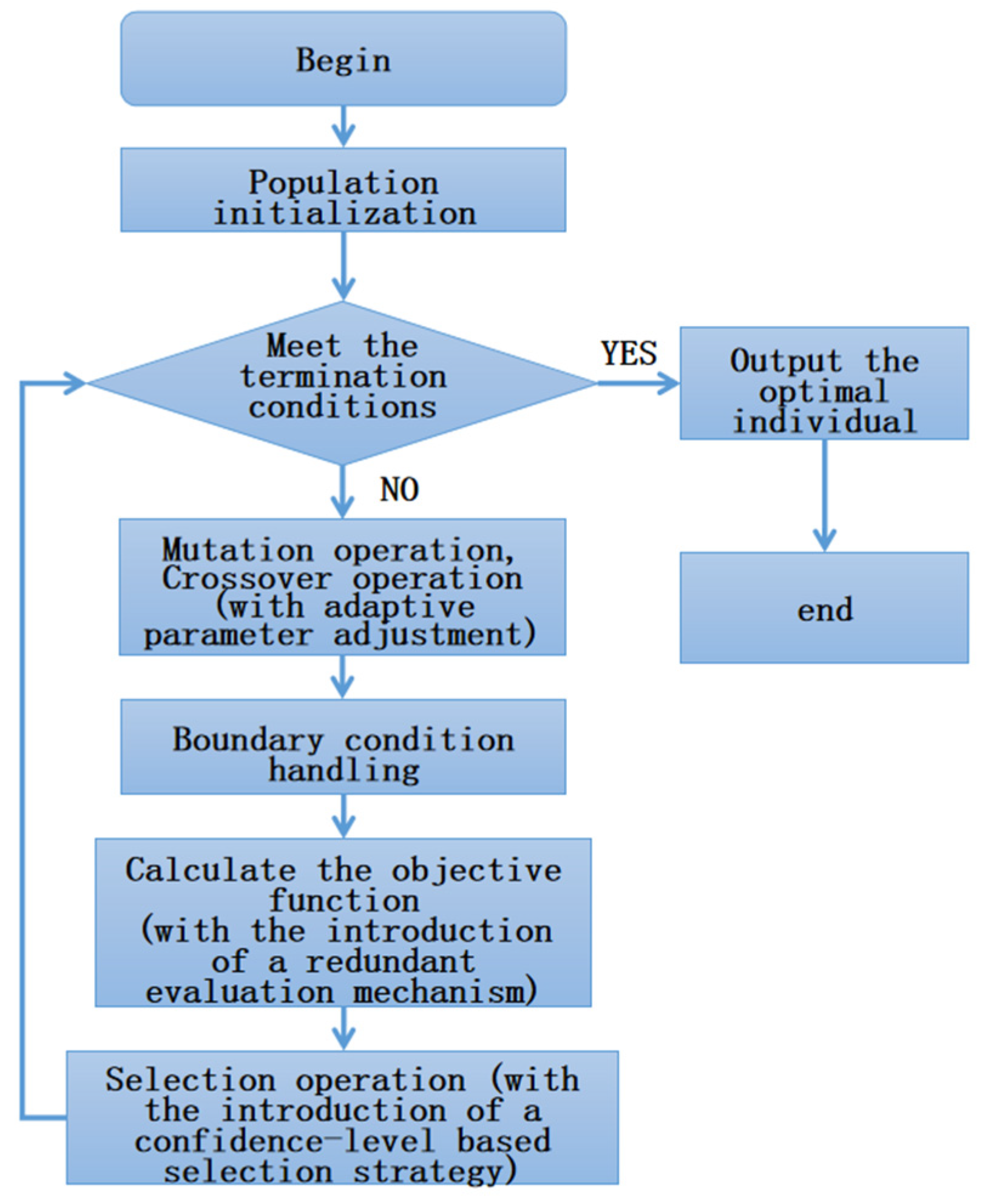
In this way, the selection strategy introduces the handling of uncertainty into the estimation of the objective function. The operational process of the improved differential evolution algorithm with hybrid strategy is shown in
Figure 6.
4. Simulation Experiment
4.1. Simulation Experiment One
Airspace model: A square mission airspace with a side length of 10 km is delineated and divided into small grids with a granularity of 100 m based on latitude and longitude coordinates. The airspace is divided into a 100 × 100 grid, and each small grid is encoded according to the coding method of the rectangular coordinate system.
UAV model: Taking a certain model of civilian medium-low altitude multi-purpose rotary-wing unmanned aerial vehicle as an example, the operational parameters of the UAV during the simulation process are shown in
Table 1. Based on the performance and size of the UAV, the radius of the UAV’s outer protection zone is determined to be 100 m, and the height of the cylindrical protection zone is 30 m.
Simulation environment: Huawei laptop, Core i7 processor, Windows 10 system, Python 3.8 environment.
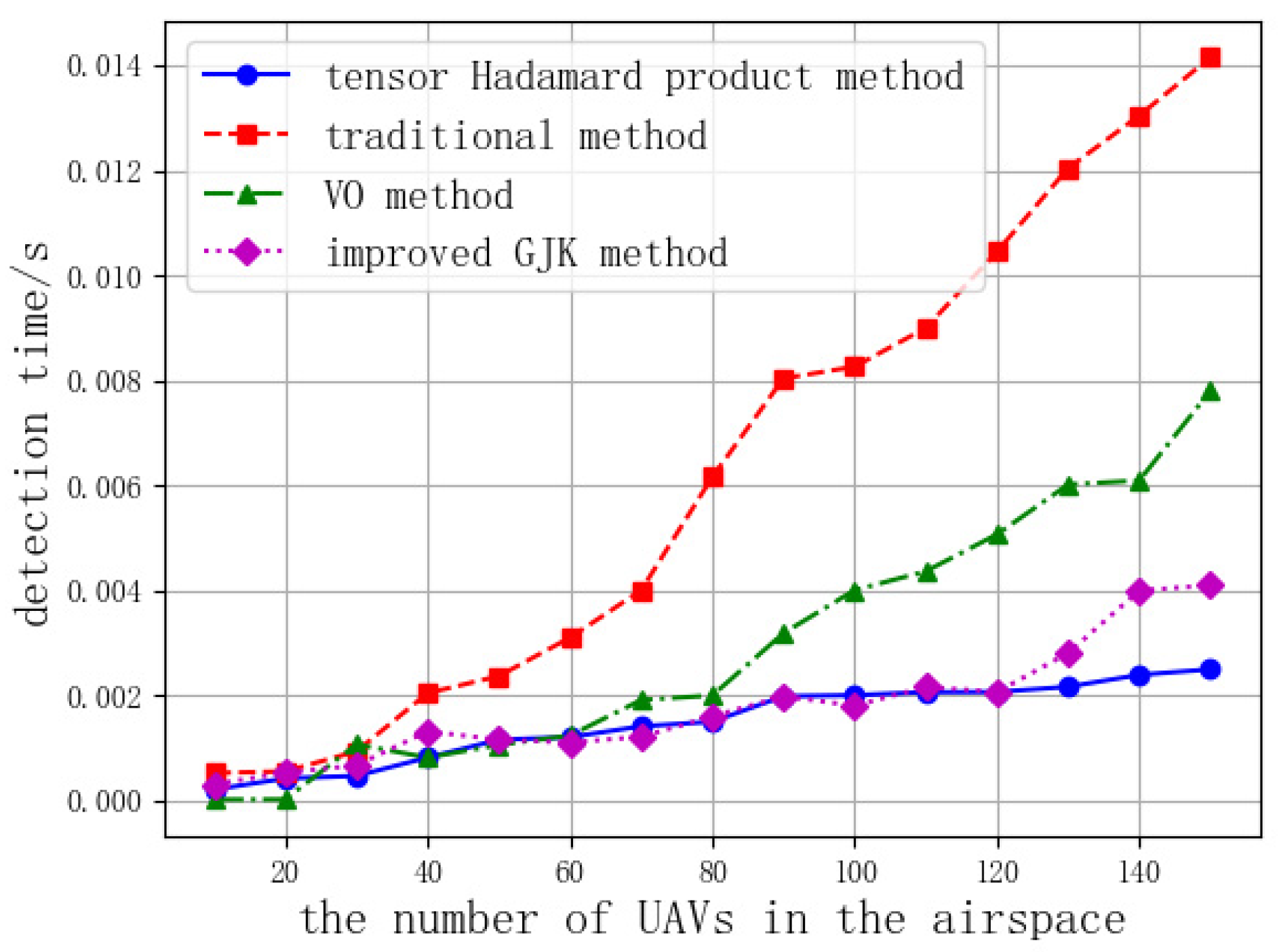
Simulation process: A number of UAVs are randomly generated within the airspace to move according to set parameters with random headings. A sequence of UAV operational altitude layers is set (100 m, 200 m, 300 m). When UAVs are generated, a random altitude layer from the sequence is chosen as the operating altitude. Then, flight conflict detection is conducted using four methods: the Hadamard product method, the traditional Euclidean formula method, the velocity obstacle (VO) method [
20], and the improved GJK detection algorithm [
21]. When the number of UAVs generated in the airspace is 10, 20, 30 ... 150 and 200, 300, 400 ... 800, the detection times of the four methods are recorded and compared, as shown in
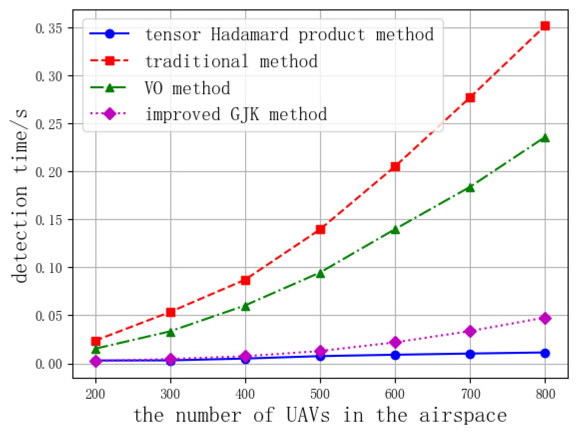
Figure 7 and
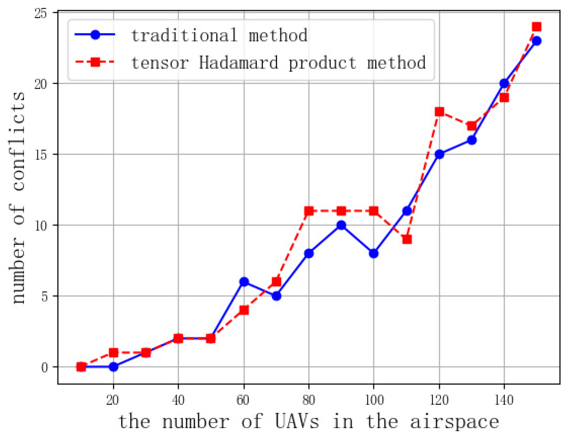
Figure 8, to analyze the efficiency of the four methods in detecting conflicts between UAVs. When the number of UAVs generated in the airspace is 10, 20, 30 ... 150, the number of conflicts detected by the traditional Euclidean formula method and the tensor Hadamard product method for different numbers of UAVs is compared, as shown in
Figure 9, to analyze the accuracy of the conflict detection method based on the tensor Hadamard product.
A partial screenshot of the UAV conflict resolution simulation process is shown in
Figure 10. In the figure, the circles represent the projection of the UAV’s protection zone on a two-dimensional plane. UAVs without conflicts and their protection zone boundaries are marked in blue, while UAVs with conflicts and their protection zones are marked in red. The grids occupied by the UAV protection zones are marked with the corresponding prime numbers, and the height marker of the UAV is located at the lower right side of the UAV.
Simulation conclusions and analysis: When the number of UAVs in the airspace is relatively small, there is little difference in computation speed among the four detection methods. However, as the number of UAVs in the airspace increases, the time consumption of traditional detection methods and the velocity obstacle method grows exponentially. In contrast, the computation times for the tensor Hadamard product detection method and the improved GJK detection method remain relatively short. Especially when the number of UAVs exceeds 200, the efficiency of the tensor Hadamard product detection method and the improved GJK detection method is significantly higher than that of traditional methods and the velocity obstacle method. In terms of algorithm performance, the tensor Hadamard product detection method outperforms the improved GJK detection method. Especially when the number of UAVs exceeds 200, the tensor Hadamard product detection method can detect conflicts within 1 millisecond, and when there are 800 UAVs, it only takes 3.267 milliseconds to detect all conflicts, whereas traditional methods require 0.3512 s to complete the detection. The more UAVs there are, the more pronounced the performance advantage of the tensor Hadamard product detection method becomes. Therefore, using the tensor Hadamard product and prime factorization methods requires less time to detect flight conflicts among large numbers of UAVs and wins more valuable time for conflict resolution.
By comparing the relationship between the number of UAVs and the number of detected conflicts, it can be seen that when the number of UAVs is the same, the number of detected conflicts does not differ significantly. The conflict detection accuracy of traditional Euclidean formula detection method is 100%. Through comparison, it can be seen that the tensor Hadamard product detection method has high accuracy and reliability in detecting conflicts.
4.2. Simulation Experiment Two
In this simulation experiment for UAV conflict resolution, three scenarios are constructed: a two-aircraft conflict, a three-aircraft conflict, and a four-aircraft conflict. Respectively, traditional differential evolution (DE), adaptive differential evolution (ADE), and hybrid improved differential evolution (HIDE) algorithms, as well the as genetic algorithms (GA) and ant colony algorithms (ACO) used in references 6 and references 10, are applied to resolve flight conflicts. The effectiveness of the HIDE algorithm in resolving flight conflicts in different conflict scenarios is judged by analyzing and comparing the convergence curves of the optimal values of the five resolution algorithms.
4.2.1. Model and Algorithm Parameter Settings
To ensure the accuracy of conflict resolution, a 600 m × 600 m square airspace is divided into 600 × 600 small grids of 1 m × 1 m. The base radius of the cylindrical outer protection zone of the UAV is set to 100 m, the base radius of the inner protection zone is set to 50 m, and the cruising speed of the UAV is set to 20 m per hour. Based on this model, three types of differential evolution algorithms are adopted to adjust the heading and speed of conflicting UAVs in a composite manner to resolve flight conflicts. The initial parameters of the three DE algorithms are shown in
Table 2:
4.2.2. Two-Aircraft Conflict Scenario Simulation Experiment
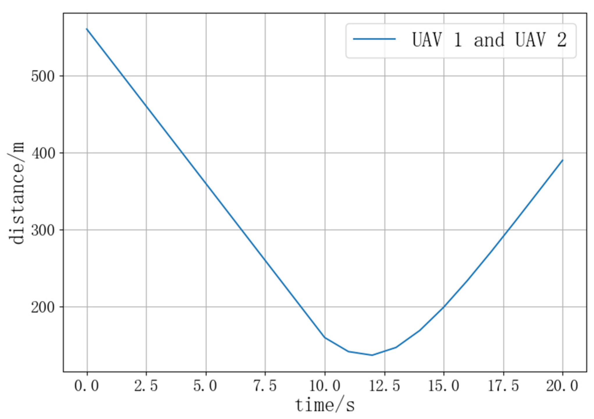
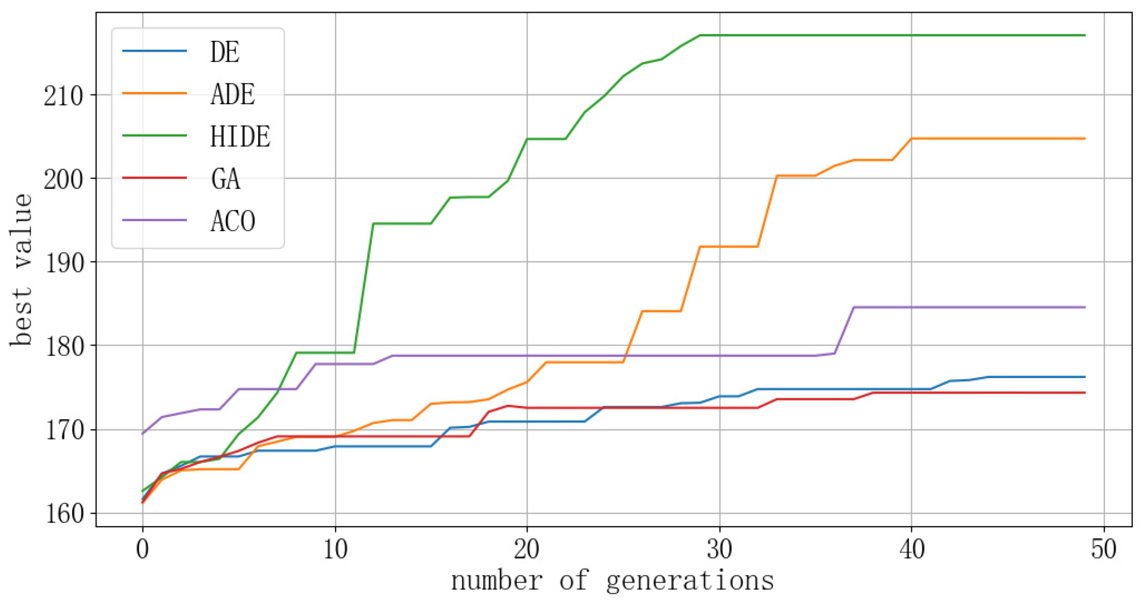
The starting and ending positions of UAV1 are (0, 300) and (600, 300), respectively, while those of UAV2 are (600, 300) and (0, 300), respectively. The two UAVs have a heading angle of 180°, simulating a head-on conflict. The optimal value convergence curves of the three DE algorithms are compared in
Figure 11, and the distance between UAVs during the simulation process is shown in
Figure 12.
4.2.3. Three-Aircraft Conflict Scenario Simulation Experiment
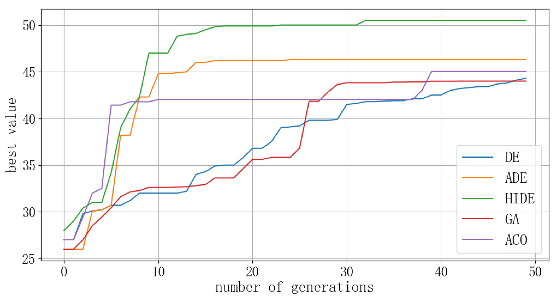
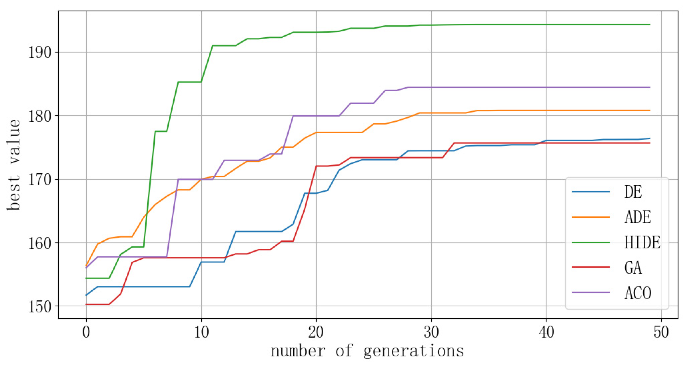
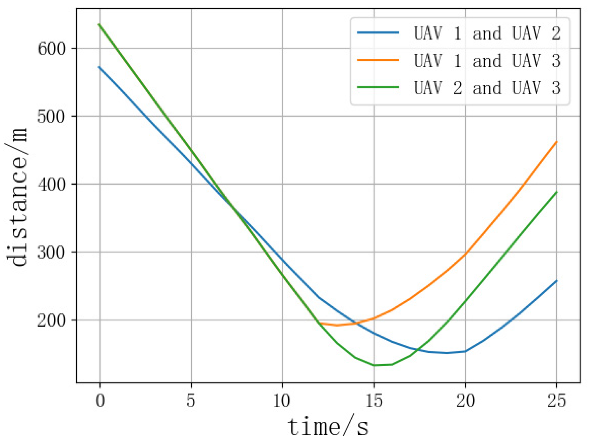
The starting and ending positions of UAV1 are (0, 0) and (600, 600), respectively, those of UAV2 are (600, 0) and (0, 600), respectively, and those of UAV3 are (300, 600) and (300, 0), respectively. The three UAVs are heading at an angle of 120° toward each other, simulating a three-aircraft cross conflict.
In the three-aircraft conflict, since there are multiple aircraft in the resolution process, the resolution results lead to different changes in heading and speed for each UAV. One UAV completes the resolution first, with the aim of increasing the resolution rate and preventing UAVs from remaining in an unsafe state for a long period of time. Then, the three DE algorithms continue to be applied for the second round of resolution to the remaining two UAVs. The results of the two resolution simulations are shown in
Figure 13,
Figure 14 and
Figure 15.
4.2.4. Our-Aircraft Conflict Scenario Simulation Experiment
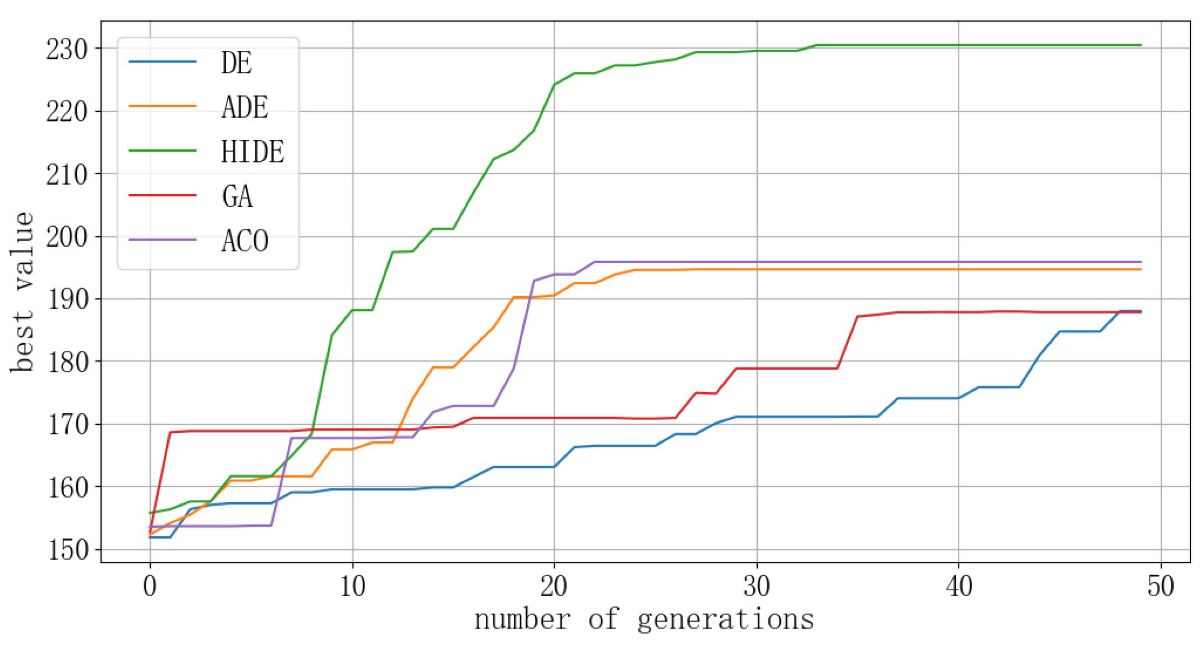
The starting and ending positions of UAV1 are (0, 300) and (600, 300), respectively, those of UAV2 are (600, 300) and (0, 300), respectively, those of UAV3 are (300, 0) and (300, 600), respectively, and those of UAV4 are (300, 600) and (300, 0), respectively. The heading angles between the four UAVs are 90° to each other.
As before, in the four-aircraft conflict, due to multiple aircraft in the resolution process, the resolution results lead to different changes in heading and speed for each UAV. The algorithm first completes the conflict resolution for two of the UAVs, in order to increase the resolution rate and prevent UAVs from remaining in an unsafe state for a long time. Therefore, the three DE algorithms continue to be applied for the second round of resolution to the remaining two UAVs. The results of the two resolution simulations are shown in
Figure 16,
Figure 17 and
Figure 18.
4.2.5. Experimental Result Analysis:
By analyzing the optimal value convergence curves of the three DE algorithms, it can be concluded that in different conflict scenarios, the ADE algorithm enhances performance on the basis of the traditional DE algorithm by adjusting the parameters of mutation rate and crossover rate. Nonetheless, the HIDE algorithm enhances performance even more by introducing an adaptive adjustment mechanism for parameters, a redundant evaluation mechanism, and a confidence level-based selection strategy. Not only that, the computational efficiency and the conflict resolution effectiveness are better when compared to both the ADE algorithms and traditional DE algorithms. By comparing the convergence curves of the optimal values with those of GA and ACO, it can be seen that the mixed improved differential evolution algorithm has superior convergence and optimal values compared to GA and ACO. This effect is particularly evident in the resolution of conflicts in complex multi-aircraft scenarios.
Analyzing the distance curves reveals that during the resolution process of the HIDE algorithm, only the optimal value of the fitness function for the second resolution in the three-aircraft conflict is 194.29, and all other optimal values are greater than 200, ensuring the effectiveness of the UAV conflict resolution. Analysis of the distance curves during the resolution process reveals that the minimum distances between UAVs in the three scenarios are 137.08, 132.50, and 126.56, respectively, all of which did not invade the inner protection zone of the UAVs. This ensures the rapid and accurate conflict resolution under the premise of UAV flight safety. For multi-aircraft conflict resolution through two rounds of DE algorithms, it fully utilizes the advantage of DE algorithms in solving continuous optimization problems and reflects the advantage of the HIDE algorithm in resolving complex conflict scenarios [
22].
5. Conclusions
For conflict detection problems associated with large numbers of UAVs in battlefield airspace, a detection method based on tensor Hadamard product operation and prime factorization has been proposed. By constructing UAV protection zone models and dividing the airspace into grids, using grids to characterize the UAV protection zones, and utilizing tensor operations and the properties of composite prime factorization, it is possible to detect conflicts between UAVs with just one calculation, regardless of the number of UAVs. This reduces the complexity of conflict detection calculations from ) to , overcoming the problems of complicated computation and long time consumption of the traditional detection method. For high-density UAV conflicts, simulation results indicate that this method significantly improves the efficiency of conflict detection among large numbers of UAVs, greatly reducing program runtime and enhancing detection efficiency during large-scale UAV operations.
Regarding the UAV conflict resolution issue, this paper has leveraged the advantages of DE algorithms in solving continuous optimization problems for simulated resolution. By introducing three strategies—adaptive parameter adjustment, redundant evaluation mechanisms, and confidence level-based selection strategies—improved hybrid DE algorithms are proposed. The simulation results demonstrate that this approach greatly enhances the resolution capability of DE algorithms. It also shows good convergence and accuracy in resolving complex conflict scenarios such as three-aircraft and four-aircraft conflicts, which is of great significance for resolving various conflicts involving large numbers of UAVs in battlefield airspace.


