1. Introduction
Self-excited oscillation noise arises when fluid flows through a cavity, while acoustic resonance noise occurs due to the cavity’s structural characteristics. When these two types of noise—self-excited oscillation and acoustic resonance—interact, they can lead to significant noise issues [
1,
2,
3]. This interaction is common in various engineering applications, such as gas transmission ducts with closed branches [
4], automotive sunroofs [
5,
6], landing gear bays, and weapons bays [
7,
8]. The combination of self-excited oscillations and resonant interactions in these cavity structures can result in severe noise pollution and even structural damage. As a result, increasing attention is being directed toward addressing this issue.
Various methods exist to control cavity self-sustained oscillation noise, including both active and passive control strategies. Active control methods [
9,
10] involve supplying additional energy, such as through plasma actuators [
11], oscillatory flow excitation [
12], upstream mass injection [
13], three-dimensional steady blowing [
14], and high-speed upstream injection [
15]. In contrast, passive control methods do not require extra energy and focus on modifying the cavity’s shape. Examples include Aft-Ramp Cavities, placing a cylinder upstream [
16], altering the trailing edge shape [
17], utilizing wavy surfaces [
18], implementing high-frequency vortex generators [
19], incorporating porous media [
20], employing a spanwise array of leading-edge tabs, and adding sub-cavities [
21].
Many researchers have studied passive control methods for cavities due to their simplicity and effectiveness. Existing research mainly focuses on geometric optimizations of the leading edge, trailing edge, and inner wall. Trailing-edge geometry directly influences the feedback mechanism in cavity flows, thereby controlling self-sustained oscillations. Hassan et al. [
16] explored noise reduction by placing a cylinder upstream of the cavity and discovered that both regular and shaped cylinders had a similar effect in suppressing cavity resonance. The vortex structure’s impact near the downstream corner remained almost unchanged with or without passive control. Abderrahmane et al. [
18] investigated the use of wavy surfaces on the leading edge at low Mach numbers, demonstrating a significant reduction in self-sustained oscillations and overall sound pressure levels. The geometry of the leading edge plays a critical role in the development of shear layers. Saddington [
22] investigated the noise suppression effects of leading-edge spoilers in transonic cavities, finding that sawtooth spoilers effectively reduced cavity resonance by approximately 8.13 dB. Lu [
23] studied the impact of leading-edge grooves in low-speed deep cavities and demonstrated that optimized grooves disrupted shear layer dynamics, significantly reducing tonal noise. Similarly, Singh [
24] explored a spanwise array of leading-edge tabs in supersonic cavity flows, showing that the tabs stabilized the shear layer, altered resonance frequencies, and effectively reduced pressure fluctuations within the cavity. Trailing-edge geometry directly influences the feedback mechanism in cavity flows, thereby controlling self-sustained oscillations. Liu et al. [
17] examined how trailing edge geometry affects cavity noise, finding that modifying the shape near the trailing edge influences the feedback mechanism and helps to suppress self-sustained oscillations. Zhao et al. [
25] studied the effect of serrated and rounded trailing edges on cavity flow and measured oscillation noise at various velocities. Their results indicated that convective modes contribute to low-frequency pressure fluctuations, while acoustic modes affect both low- and high-frequency fluctuations. The rounded trailing edge was more effective than the serrated structure in controlling flow. Çelik and Demir [
26] used stair-stepped aft walls and spoilers to reduce transonic cavity noise, significantly lowering overall sound pressure levels (OASPL). Martin [
27] showed that geometric modifications, including cavity length and edge radii, reduced noise by up to 9 dB. Naseer et al. [
28] conducted a numerical study on deep cavity noise suppression by exploiting aeroacoustic–structural interactions. They designed multiple elastic panels strategically arranged to passively suppress deep cavity noise, examining the underlying physics through direct aeroacoustic simulations. Bo et al. [
29] studied porous cavity floors and found that back pressure adjustments could influence flow dynamics and reduce noise, with sawtooth spoilers achieving up to 8.13 dB noise reduction. Bacci [
30] utilized Hilbert–Huang spectral analysis to study cavity flows incorporating fluidic spoilers. Their work identified energy dynamics within the cavity, aiding the optimization of spoiler configurations for enhanced noise control. Li [
31] examined aerodynamic noise characteristics and control methods for non-fully open low-speed cavities. They highlighted the effectiveness of geometric modifications tailored to low-speed flows, reducing both tonal and broadband noise. Panigrahi [
21] found that sub-cavities reduce cavity oscillations, with placement on both front and aft walls lowering dominant mode pressure by 34.9 dB and overall pressure by 14.5 dB. Ali [
32] experimented with aft-wall ramp cavities, showing that smaller ramp angles effectively suppressed oscillations and controlled flow entrainment. Ren et al. [
33] used simulations to investigate the influence of cavity structure and Mach number on pressure waves, finding that the trailing edge ramp angle reduced static pressure on the bottom wall, decreased shear layer vortex interaction, and significantly lowered acoustic pressure in the dominant mode. Krishna [
34] experimentally studied various rear-face geometries, modifying them with single, double, and partial ramps. The double ramp configuration reduced overall sound pressure by 10 dB, demonstrating the noise reduction potential of trailing edge ramps and slanted wall surfaces.
The passive control measures mentioned above primarily address self-excited oscillation noise. However, in many engineering applications, the coupling between self-excited oscillations and acoustic resonance is a critical issue that remains underexplored. In locked-on states, where both phenomena coexist, the dominant mode aligns with acoustic resonance, making it difficult to predict using Rossiter’s formula. While significant progress has been made in cavity noise control, most studies focus on high-speed conditions or single geometric modifications, such as changes to the front or rear walls. In contrast, low-speed deep cavities, where coupling between self-sustained oscillations and acoustic resonance is particularly pronounced, have received little attention. Specifically, the influence of slanted front and rear wall configurations on coupled noise dynamics remains systematically unexplored.
The passive control measures mentioned above primarily address self-excited oscillation noise. However, in many engineering applications, coupling between self-excited oscillation and acoustic resonance noise occurs, and there is limited research on reducing this type of coupling noise. When a cavity enters a locked-on state where both self-excited oscillation and acoustic resonance noises are present, the dominant mode typically aligns with acoustic resonance, making its frequency difficult to predict using Rossiter’s formula.
This paper explores how different slanted inner wall configurations affect the dominant mode of locked-on cavity noise and reduce the overall sound pressure level. The acoustic characteristics of various slanted wall surfaces are investigated in the D7 aeroacoustic wind tunnel at Beihang University, focusing on the impact of wall slant angles on cavity-coupled noise. The noise reduction effects of different slant configurations are also compared. The paper is structured as follows:
Section 2 outlines the experimental methods and setup,
Section 3 presents the noise characteristics of the slanted wall configurations, and
Section 4 provides a summary of the conclusions.
2. Experimental Setup
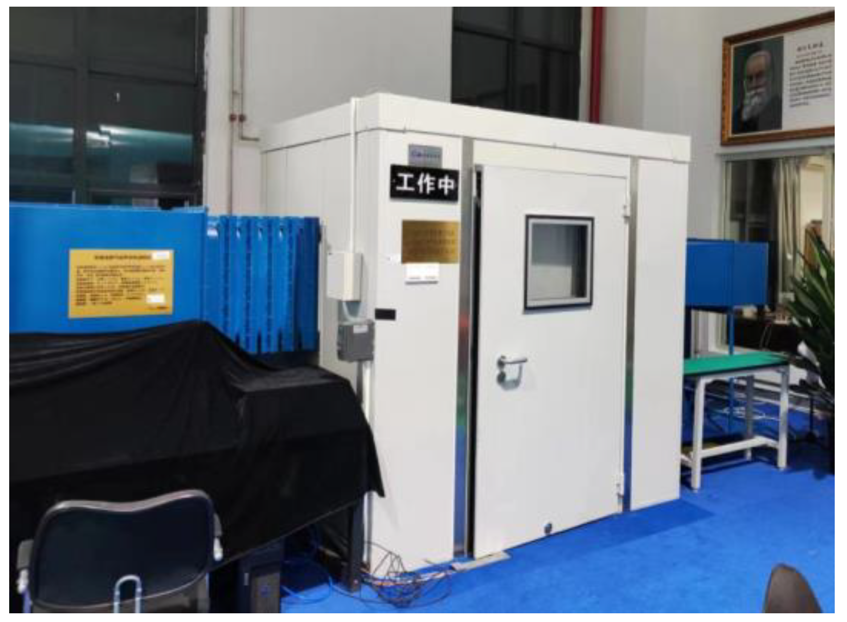
The experiment described in this paper was carried out in the D7 wind tunnel at Beihang University (Beijing, China), with a focus on measuring aerodynamic noise and cavity velocity. The D7 wind tunnel is a small, closed-circuit system featuring a low-noise fan and a micro-porous plate muffler in the power section to reduce noise. Additionally, the tunnel walls are lined with soundproof material for further noise reduction. The test section is 500 mm long with a square cross-section of 200 mm × 200 mm. Turbulence in the jet core is maintained at less than 0.1%, and the experimental wind speed ranges from 0.1 to 40 m/s. The test section is enclosed by a small anechoic chamber, as shown in
Figure 1, with dimensions of 1.4 m in length, 1.6 m in width, and 1.9 m in height.
The cavity model is mounted on a plate that runs parallel to the flow direction, with the plate’s leading edge connected to the wind tunnel nozzle, and the cavity positioned 100 mm downstream from it. Both the flat plate and cavity are made of aluminum alloy. Two microphones were used simultaneously during the experiment. As shown in
Figure 2, Mic2 is a Brüel & Kjær Type 4189 1/2” microphone (Brüel & Kjær, Nærum, Denmark) for measuring far-field noise, positioned 470 mm directly above the rear edge of the cavity. Mic1, a G.R.A.S. 1/4” surface microphone (G.R.A.S. Sound & Vibration, Holte, Denmark), was placed on the front surface of the cavity’s inner wall when testing the slanted configuration of the rear wall. The flow field data were acquired using a StreamLine CTA (Constant Temperature Anemometer) (Dantec Dynamics, Skovlunde, Denmark) from DANTEC. A single one-dimensional hot-wire probe 55P11, as shown in
Figure 1, was positioned 13 mm directly above the center of the cavity’s rear edge. The sampling frequency for both the hot-wire signals and acoustic signals is 25,600 Hz, with a sampling time of 50 s. When analyzing these signals using Fast Fourier Transform (FFT), the Tukey–Hanning window function is applied. The FFT is set to 6400 points with a 50% overlap, resulting in a frequency resolution of 4 Hz. The FFT results of each segment are subsequently averaged to improve the spectral accuracy.
Different wall slant configurations were investigated experimentally to control self-excited oscillation noise for cavity configurations where self-excited oscillation noise and acoustic resonance noise are coupled. Previous studies have shown that a cavity of 80 mm in length, 60 mm in width, and 120 mm in depth has a coupled noise, so this configuration was chosen as the base configuration. The dimensional parameters of the inner wall slant configuration in the experiments are shown in
Figure 3. The experimental design of the front and rear wall slant configurations, where β is the slant angle, was carried out for a total of eight noise reduction configurations with four slant angles of 9°, 18°, 27°, and 34° on the inner wall, respectively. Experimental far-field noise measurements were carried out for the different configurations with the microphone located 470 mm directly above the rear wall surface of the cavity. The experimental measurement velocity ranges from 10 m/s to 35 m/s, with a flow velocity interval of 1 m/s.
3. Results and Discussion
The experimental results are shown in
Figure 4 and
Figure 5, which are the effects of wall slant configuration on the far-field noise power spectrum density.
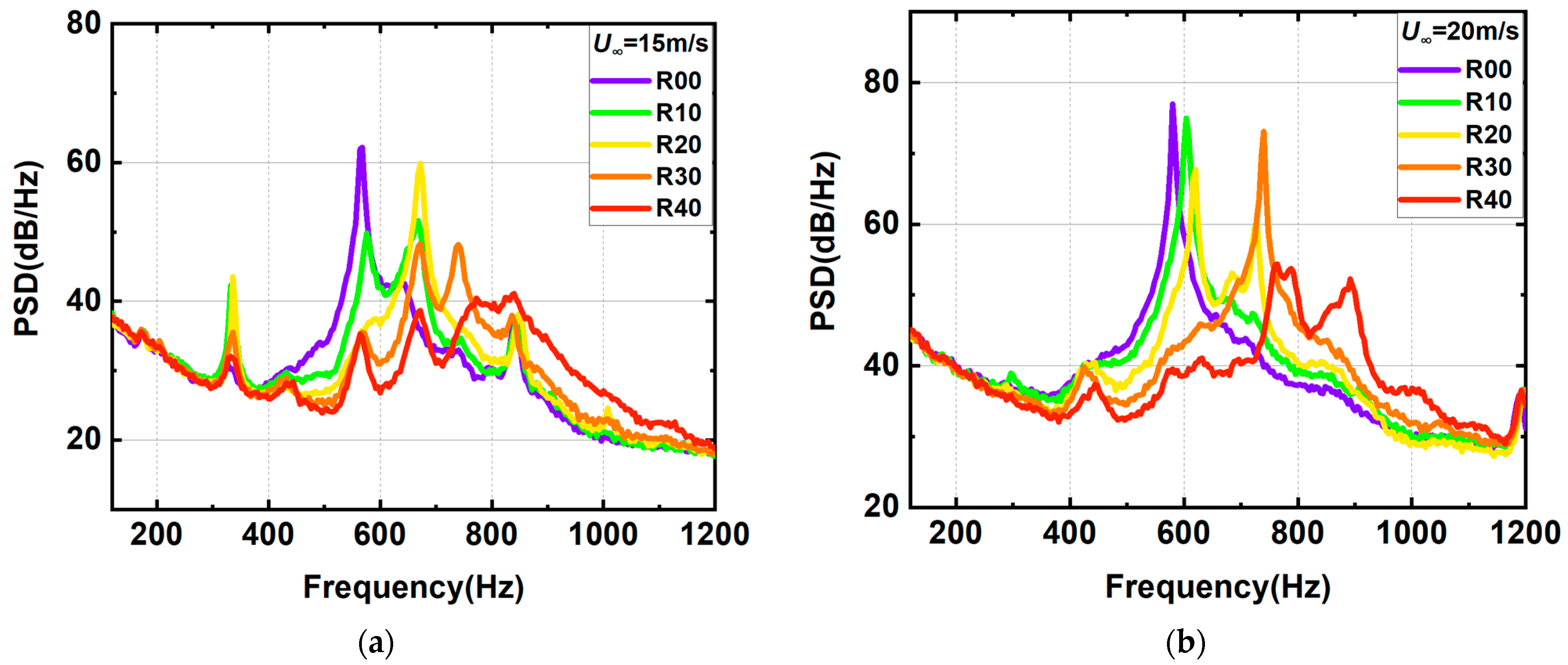
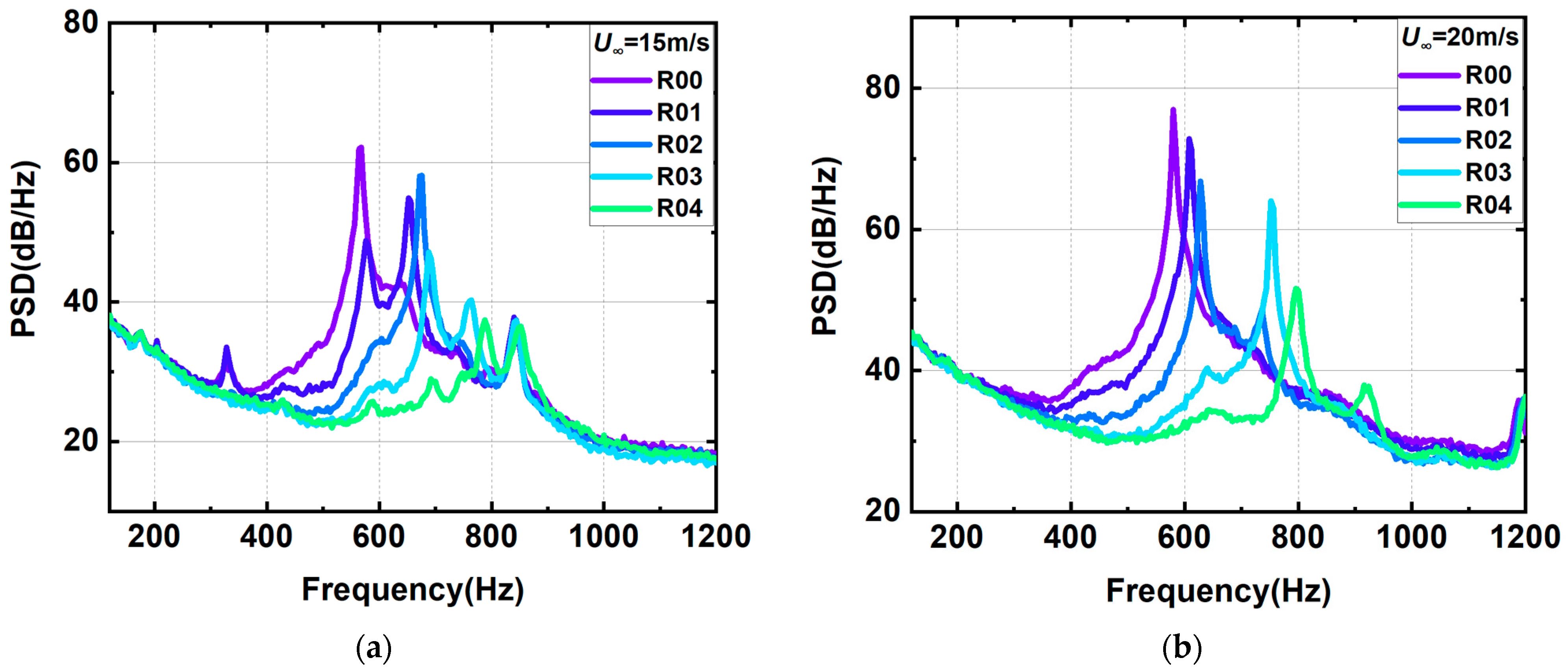
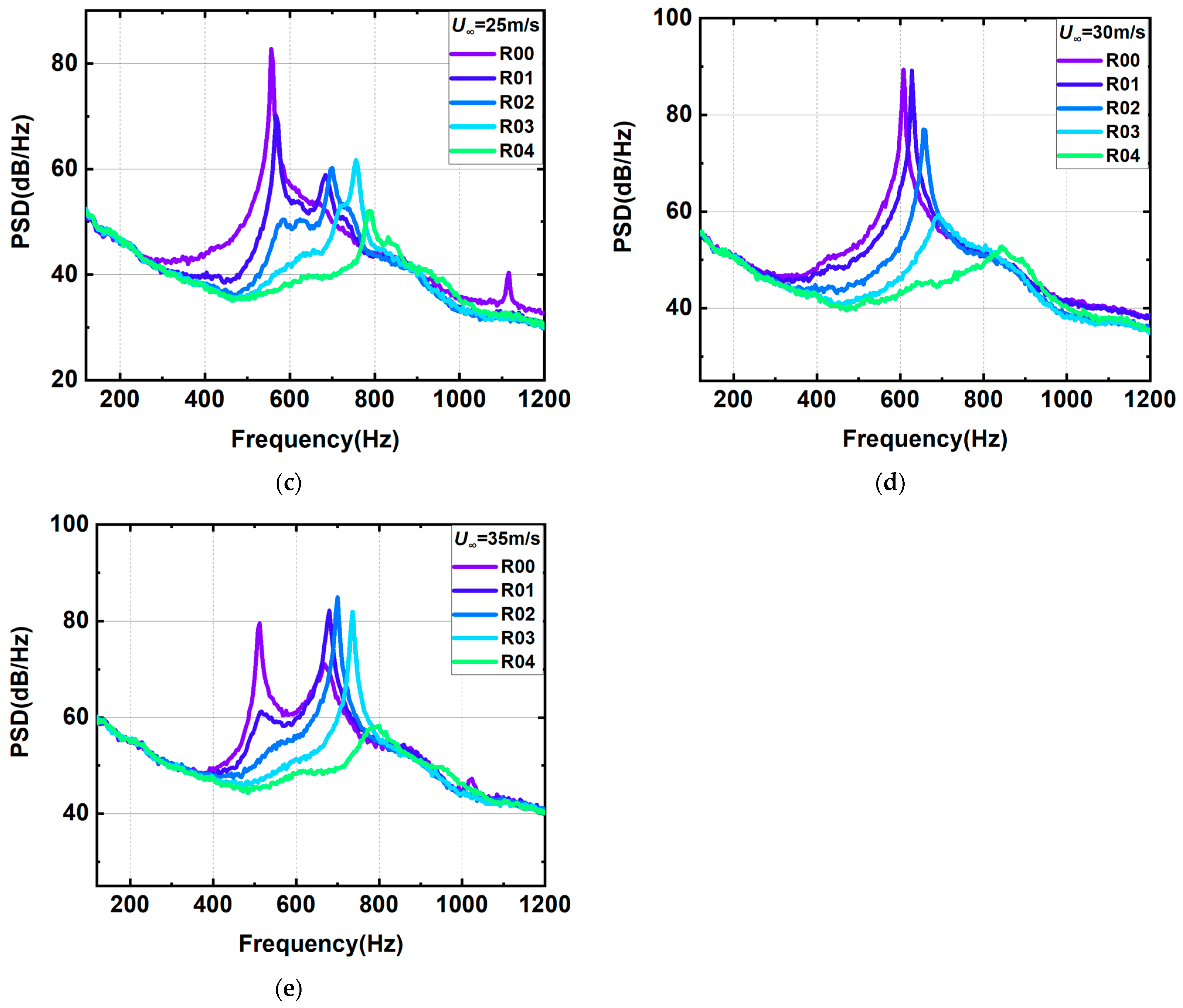
Figure 4 shows the noise spectrum of the front wall slant configuration. The discrete noise of self-excited oscillation still exists after the front wall slant, and the discrete noise can be observed at all slant angles. When the velocity is 15 m/s, the intensity of discrete noise of self-excited oscillation decreases gradually with the increase in slanting angle. Furthermore, the frequency of the discrete noise and the number of excited modes also change. And the effect at other velocities is similar to the above description. However, when the velocity is 30 m/s, the discrete noise intensity of the front wall slant configuration increases compared to the original configuration, which may be due to the change in the coupling situation after the wall slant. This situation is worth further investigation because it involves the coupling of acoustic resonance and self-excited oscillation noise. The noise contrast of the rear wall slant configuration is shown in
Figure 5, which basically shows that the intensity of discrete noise decreases as the slant angle increases.
According to the analysis of the baseline configuration in this paper [
35], the locking-on noise of the self-excited oscillation and the first-depth acoustic resonance mode exists in the baseline configuration. For comparison, the far-field background noise without the cavity will be presented in the subsequent analysis, highlighting the prominent acoustic characteristics of the baseline configuration. The variation in the noise in the inner wall slant configuration may be due to the change in the acoustic resonance mode after the wall slant in the cavity. The change in the inside structure leads to a variation in the wavelength of the standing wave in the depth direction, a shift in the frequency of the first-depth mode, and thus a change in the coupling effect with the self-excited oscillation. In addition, the intensity of the broadband noise does not change, basically indicating that the slanting of the cavity wall does not suppress the impact of the shear layer on the rear wall of the cavity, but only disrupts the feedback mechanism of the self-excited oscillation noise in the cavity.
Figure 6 shows the comparison of the overall sound pressure level results for the wall slant configuration. The phenomenon of local maximum and minimum values of the overall sound pressure level of the baseline configuration will still exist for the inner wall slant configuration. This intensity variation in the far-field noise was shown in previous studies to be influenced by the locking-on noise.
Figure 6 shows the overall sound pressure level of the measured configuration compared to the variation in
, indicated by the brown line. The typical dipole sound source mechanism excitation characteristics are based on the law of
, i.e., turbulent fluctuations close to the rigid surface. Therefore, the acoustic power can be normalized by
in the absence of significant acoustic resonance or feedback in the cavity due to the interaction of the shear layer with the downstream cavity wall. As can be seen from the figure, the trends in acoustic power changes for different cavity configurations with slanted inner wall surfaces all coincide with
. However, due to the change in the effective depth of the cavity after the wall slanting, the location where the local maximum of the sound pressure level appears will change. In terms of the noise reduction effect, as shown in
Figure 6, the noise reduction improves with an increase in the slant angle. Among the measured configurations, R04 demonstrates the best noise reduction performance, achieving a maximum reduction of over 10%. Additionally, the noise reduction effect of the rear wall slant configurations (
Figure 6a) is more pronounced compared to the front wall slant configurations (
Figure 6b), as evidenced by the higher overall noise reduction percentages in
Figure 6c.
Due to the coupling effect of self-excited oscillations and first-depth acoustic resonance modes present in the configurations, the effect of the slanting of the inner wall on the noise needs to be further analyzed in terms of changing the coupling mechanism after the slanting. The coupling mechanism between self-excited oscillations and acoustic resonance has been investigated in previous papers [
35]. The key parameter affecting the coupling of acoustic resonance and self-excited oscillations was proposed in the paper to be
. The ratio
of the acoustic resonance frequency and the fundamental frequency of the self-sustained oscillation is used to quantify the deviation.
When
changes from
to
, the dominant mode is n. The maximum value of the overall sound pressure level intensity occurs at
and the corresponding frequency prediction equation for the dominant mode is Equation (2). The effect of the same slant angle on the acoustic resonance is the same whether the front or rear wall surface is slanted. Therefore, the coupling influence study is carried out for the rear wall face noise reduction configuration with a better noise reduction effect.
Since the evaluation method involves parameters such as cavity length L, acoustic resonance frequency
, and shear layer vortex convection velocity
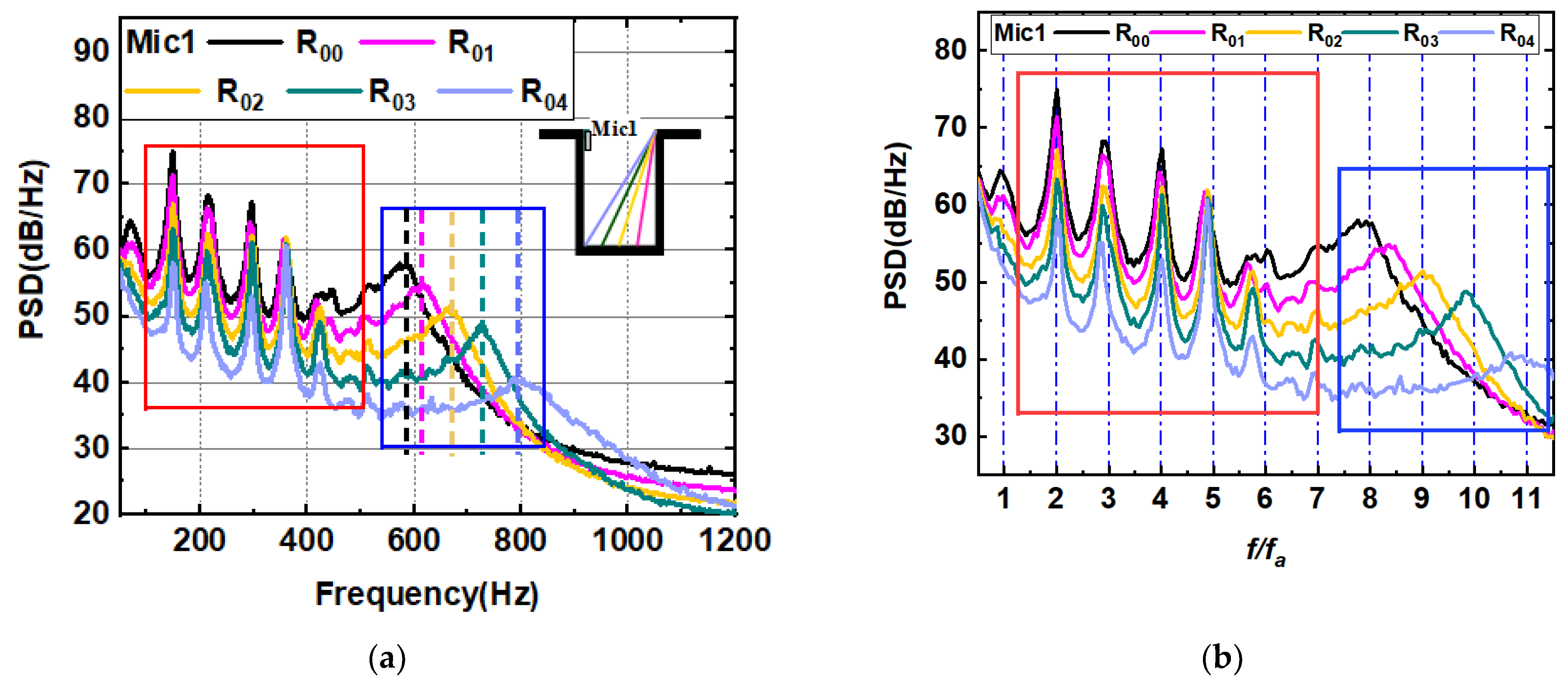
, the parameters are calculated using the methods mentioned in the paper, mainly at the lowest velocity, i.e., when the acoustic resonance has not yet coupled with the self-sustained oscillation. In practical applications, only acoustic resonant noise is not easily received by a far-field microphone, so a near-field Mic 1 is mounted on the front wall of the cavity to capture the frequency of the acoustic resonant noise. As shown in
Figure 7, the near-field noise spectrum at a velocity of 10 m/s was compared for different slanted configurations. The figure shows that at lower velocities, acoustic resonances and self-sustained oscillation noise have not yet coupled, so the multi-mode frequencies of self-sustained oscillation noise excited by different configurations are consistent at this time, with the difference between the several configurations being the different frequencies of the first-depth modal acoustic resonance noise due to the configuration changing its inside structure. According to the principle of signal modulation, the shear layer vortex convection velocity can be calculated from the interval of the self-excited oscillation frequency, so the average value of the excitation interval of the self-excited oscillation noise in the red boxed region of
Figure 7a is measured and then the dimensionless parameter κ of the vortex convection velocity is calculated by Equation (3); the results are shown in
Table 1. When we calculate
using Equation (4), the horizontal coordinates of
Figure 7a are then able to be normalized by
to obtain
Figure 7b.
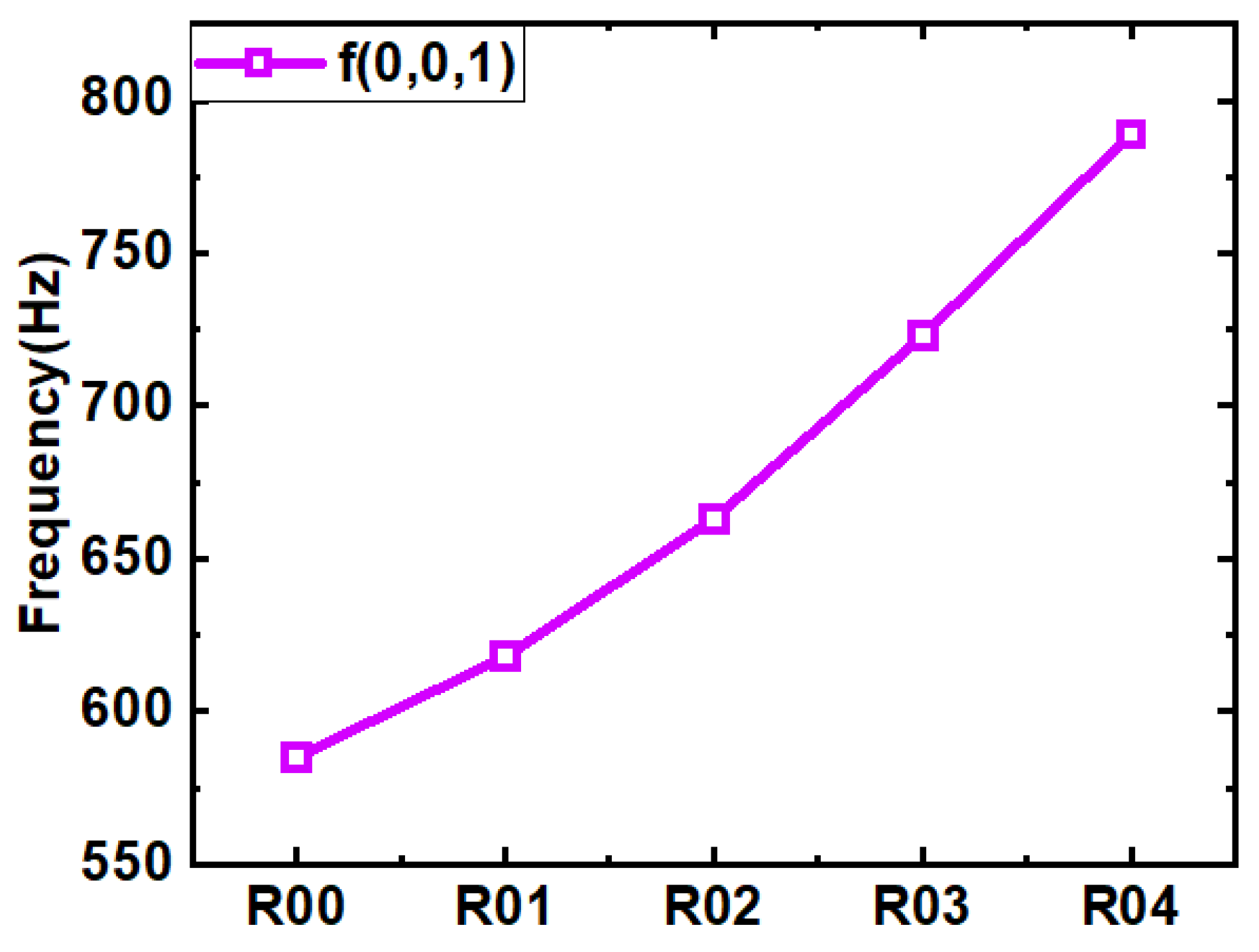
Figure 7b shows that the different modes of the different configurations of the self-sustained oscillation noise are exactly integral multiples, and the modes excited by the different configurations are consistent. The excitation frequencies in Equation (1) are acoustic resonance frequency
in this study. The acoustic resonance frequencies
are further measured for different configurations in the blue boxed region of
Figure 7a. The acoustic resonance frequencies obtained are shown in
Figure 8, where the greater the angle of slant of the inner wall, the higher the acoustic resonance frequency.
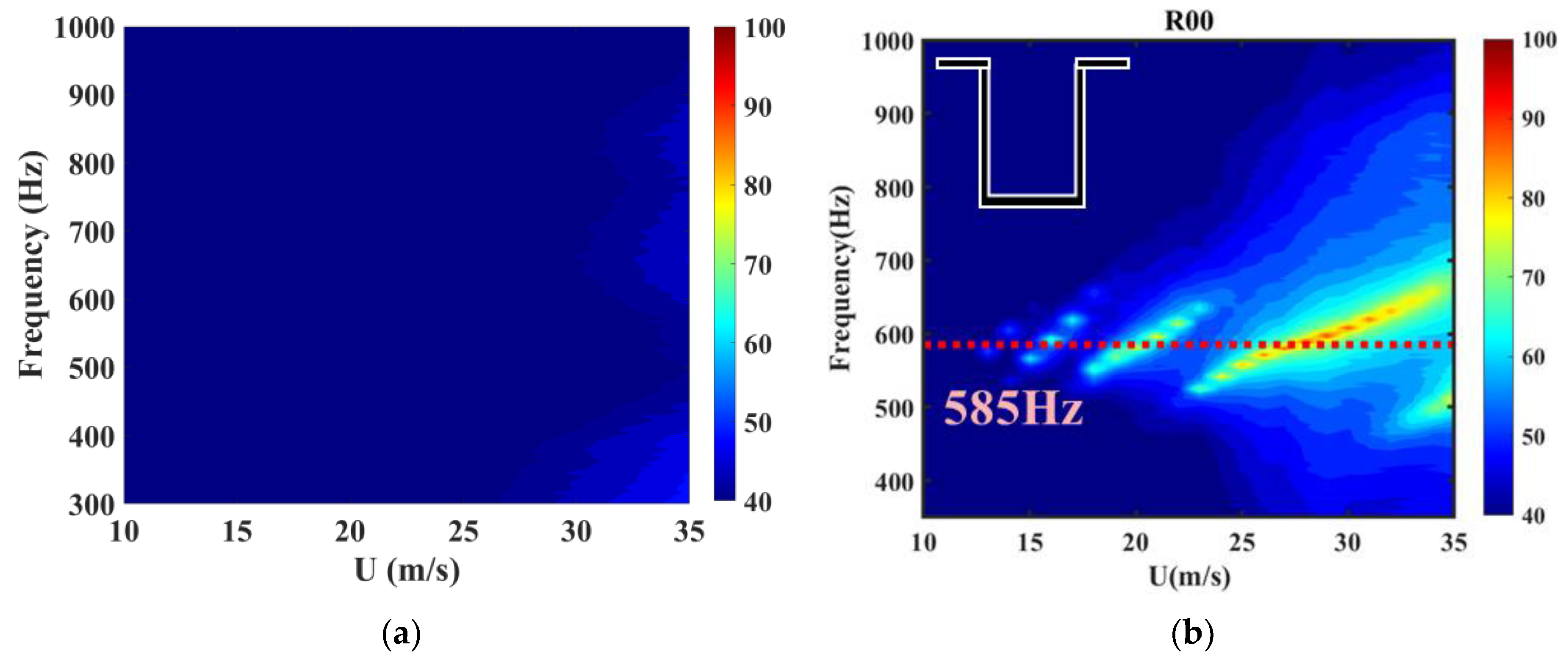
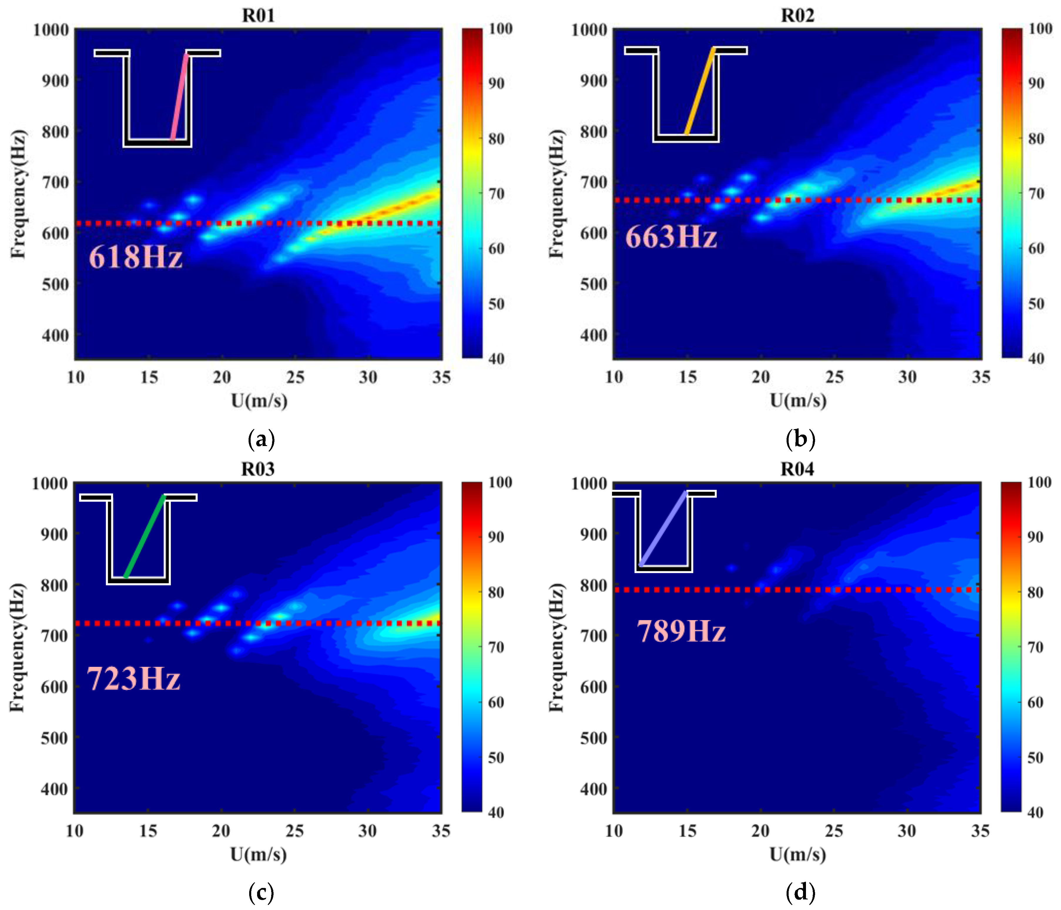
Figure 9 shows the far-field power spectral density plot for the baseline configuration, with the measured acoustic resonance frequencies shown as dashed lines in the plot, based on the acoustic resonance frequencies in
Figure 8.
Figure 9 shows the far-field power spectral density contour of the slanted configuration at the rear wall of the cavity, where the acoustic resonance frequencies are indicated by dashed lines. Firstly, comparing the noise results for the different slant configurations, the excited modes of the self-excited oscillatory noise are always concentrated near the acoustic resonance frequency due to the coupling of acoustic resonance and self-excited oscillation that occurs. The corresponding dominant mode is always near the acoustic resonance, so it is this coupling effect that leads to the appearance of local maxima in the overall sound pressure level. It is easy to see from
Figure 10 that as the acoustic resonance frequency of the different configurations gradually increases with the slant angle, the dominant mode selection is affected by the coupling effect.
The switching pattern of this dominant mode is therefore studied specifically for the two velocities of 15 m/s and 35 m/s.
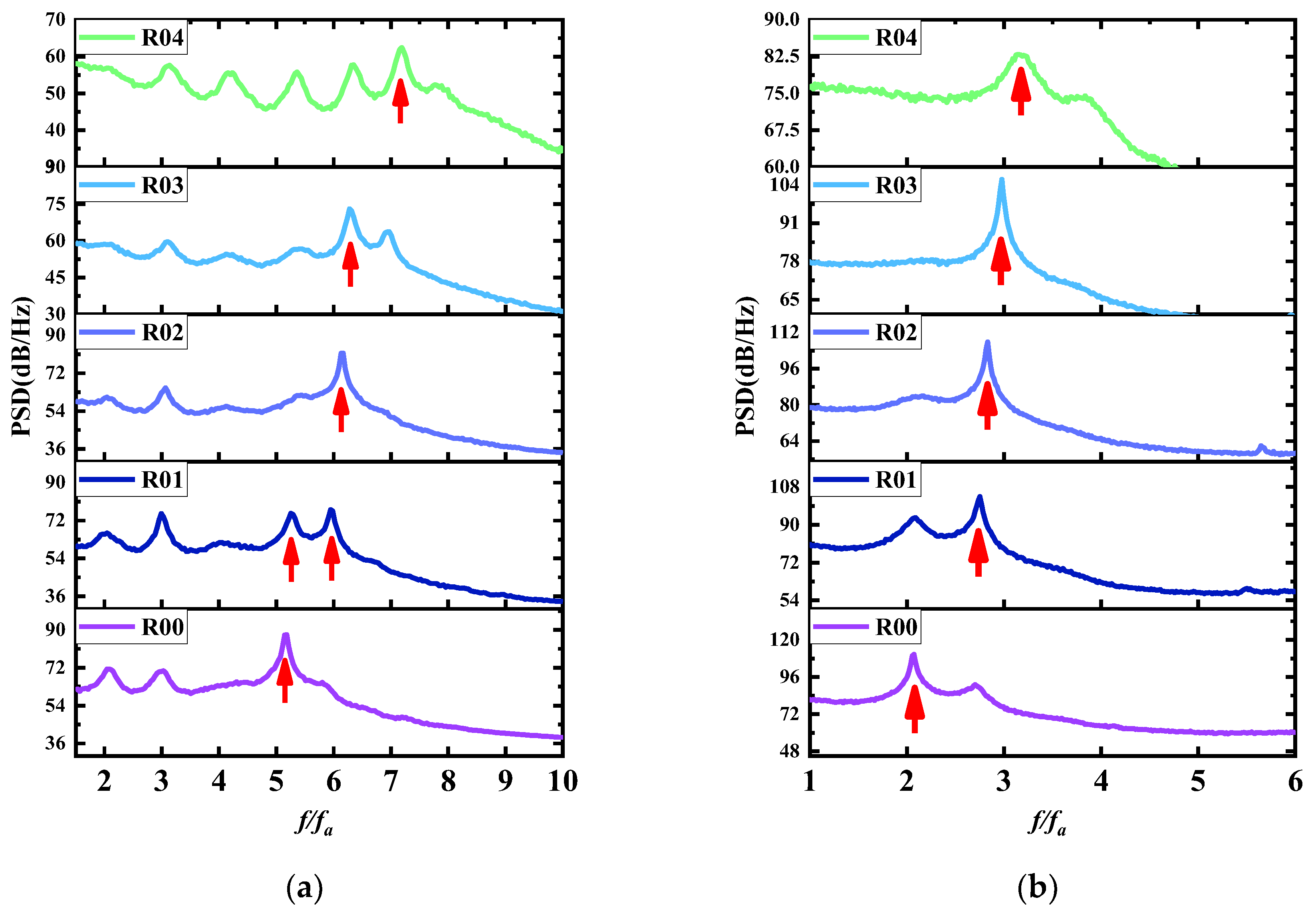
Figure 11 shows a comparison of the power spectral density at 15 m/s and 35 m/s, with the horizontal coordinates normalized according to the
calculated in Equation (4). It can be seen that the frequencies of excitation are not uniform at different slant angles and that the dominant mode of excitation changes. As the slant angle increases, the dominant mode gradually switches to a higher mode.
Figure 11 shows that when the velocity is 15 m/s, the dominant mode of the baseline configuration is mode 5 and the slant angle increases; the dominant modes of R01, R02, and R03 are mode 6, the slant angle continues to increase, and the dominant mode of the R04 configuration is mode 7. When the velocity is 35 m/s, the dominant mode of the baseline configuration is mode 2, the slant angle increases, and the dominant mode of the R01, R02, R03, and R04 configurations are all mode 3.
Building on Liu’s study [
35], which highlighted the coupling mechanism between acoustic resonance and self-sustained oscillations in cavity flows, this research further explores how varying cavity configurations influence the dominant mode selection. Liu’s findings demonstrated that the coupling effect shifts the acoustic resonance frequency and alters the phase delay term, significantly impacting the selection of dominant Rossiter modes. Extending this framework, this study examines the relationship between the non-dimensional parameter
and the dominant mode under different configurations. Based on previous research [
35], the dominant mode is n as
changes from
to
. The
for different configurations at two velocities are compared to
Figure 12. When the velocity is 15 m/s,
gradually increases from 5.25 to 7.01 as the slant angle increases, while the dominant mode changes from 5 to 6 and finally to 7. At a velocity of 35 m/s,
gradually increases from 2.37 to 3.19 as the slant angle increases, while the dominant mode changes from 2 to 3. The paper [
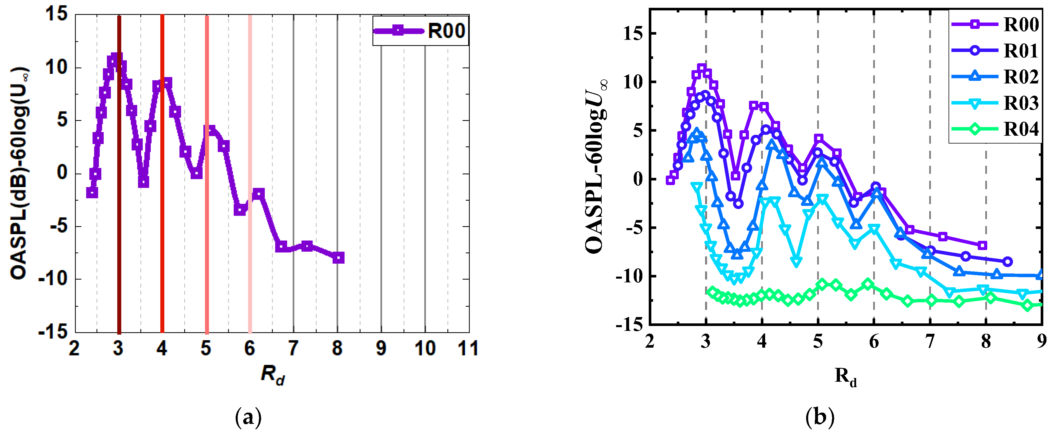
35] shows that the higher the coupling mode, the lower the effect on the overall sound pressure level, as shown in
Figure 13. Therefore, increasing the slant angle of the inner wall improves the coupling mode of the self-excited oscillation and thus the noise reduction effect.
According to Equation (1), the variation in the dominant mode is mainly due to the increase in acoustic resonance frequency. In addition, due to the effect of acoustic resonance on self-excited oscillations, the change in
value directly affects the variation in the phase delay term. And the position of the maximum normalized overall sound pressure level of the slanted wall configuration coincides, as shown in
Figure 13b. The frequency of the dominant mode for coupled noise can be estimated from Equation (2). Taking the R01 and R02 configuration as an example, the prediction of the frequency of the dominant mode for the slanted configuration using Rossiter’s formula and the formula from Liu’s study is shown in
Figure 14. It is found that the frequency of the cavity coupled noise with the inner wall slanted can be predicted more accurately using the frequency formula in Liu’s study after correction for the phase delay term. This improved the understanding of how inclination affects acoustic resonance and how oscillatory behavior can guide future designs for noise control and reduction in such systems.
The hot-wire measurements further support these findings, as shown in
Figure 15, which presents the energy spectrum of velocity fluctuations at a speed of 20 m/s. The results indicate that the dominant frequencies of velocity fluctuations align closely with the far-field acoustic results, demonstrating a strong correlation between vortex shedding dynamics and acoustic resonance within the cavity. This alignment suggests that the vortex shedding and cavity’s coupled noise (arising from the interaction between self-sustained oscillations and acoustic resonance) are consistent, highlighting a strong flow–acoustic coupling. Additionally, the comparison between velocity fluctuation spectra and acoustic spectra shows that the rear wall slant configurations significantly reduce energy in the high-frequency range compared to the baseline configuration (R00). This suggests that the slanted rear wall structure disrupts the coherence of small-scale turbulent vortices and weakens the feedback loop between vortex shedding and acoustic resonance. By doing so, the coupling mechanism between the shear layer and the cavity’s acoustic modes is suppressed, mitigating self-excited oscillations and reducing noise generation. These observations further confirm that the slanted rear wall configurations, particularly R04, effectively alter the dynamics of vortex shedding and acoustic coupling, highlighting their potential for noise mitigation in cavity flows.


