Article

Study of Starting Performance of a Series Hybrid Aero Propulsion System

School of Aerospace Engineering, Xiamen University, Xiamen 361005, China
*
Author to whom correspondence should be addressed.
Aerospace 2024, 11(1), 63; https://doi.org/10.3390/aerospace11010063
Submission received: 23 November 2023 / Revised: 29 December 2023 / Accepted: 3 January 2024 / Published: 9 January 2024

Abstract

:
Combined with the development trend of high speed generators and the high voltage of DC microgrids in high-power series hybrid aero propulsion system, a set of hybrid systems with a power of 200 kW, voltage of 540 V, and speed of 21,000 r/min is established in this article. Ground starting tests were conducted, focusing on the analysis of the coupling characteristics between the engine, generator and motors/propellers during the starting process, and further facilitated the optimization of the strategy of starting control. Firstly, the starting process of the series hybrid aero propulsion system mainly consists of four stages: the turboshaft engine is started, the gas turbine speed is increased, the controlled rectification intervenes, and the electric propeller is activated. The recommended definition of the idle state of the 200 kW hybrid propulsion system in this paper is as follows: power turbine speed NP = 10,500 rpm, grid system voltage UDC = 540 V, and the minimum stable power state of the electric motor PM = 150 W. Furthermore, experiments reveal that during the starting process, the resistance value and the rectification strategy, respectively, affect the steady-state and dynamic characteristics of the power turbine speed. By comparing multiple sets of experiments and utilizing data fitting software for optimal design, the results indicate that, based on the starting strategy of no-load protection and two-step controlled rectification, the total duration of the optimized starting process is shortened by 64.7%, and the gas turbine speed is reduced by 22.7% compared to the pre-optimized state. The starting control sequence is clearer, and the optimization effect is significant.

1. Introduction

Electric propulsion technology has become a significant development direction in the aerospace industry to meet the pursuits of aviation power systems for efficiency, fuel consumption, and environmental friendliness [1]. Compared to fully electric propulsion, hybrid propulsion has gained increasing attention in recent times due to its advantages in range time and load capacity. Hybrid aero propulsion systems mainly consist of two configuration schemes: series and parallel [2]. In the series configuration, all of the thrust is generated from propellers or ducted fans driven by electric motors, achieving complete decoupling between the engine and the propulsion system [3]. In the parallel configuration, thrust is generated jointly by the engine and electric motor, requiring fewer modifications to the traditional structure and layout [4]. In the overall plan for hybrid aero propulsion systems proposed by the IATA before 2050 [5], series hybrid systems hold a significant position and are expected to become the mainstream solution for aircrafts such as urban commuting, general aviation, and regional aircrafts.
For the series hybrid aero propulsion system, NASA has carried out the core conceptual design and ground test research targeting some pivotal aircrafts such as the N3-X wide-body aircraft [6], STARC-ABL single-aisle large aircraft [7], ECO-150 regional aircraft [8], and so on. Some advanced research laboratories like HEIST [9] and NEAT [10] have been established and developed. According to the “Flightpath 2050” plan [11], the aviation industry in EU countries has harnessed some aircrafts including E-Airbus [12], E-Fan X [13], and EcoPulse [14] to spearhead key technology development and flight demonstration validation of series hybrid aero propulsion systems. In Russia, theCentral Institute of Aviation Motors (CIAM) has verified some technical schemes of the 500 kW class series hybrid propulsion system on the Yak-40 aircraft [15]. In China, the AECC Hunan Aviation Powerplant Research Institute [16] takes the lead in developing a series hybrid aero propulsion system with a power of 80 kW, voltage of 115 V, and a single bus structure, and has completed the flight demonstration based on the modified SA60L.
The aforementioned research has effectively promoted the development of series hybrid configuration. With the continuous realization of functional verification, there is an urgent need to propose certain standardization requirements or references for series hybrid aero propulsion systems. For example, currently available technical reports and research literature mainly focus on the overall performance of hybrid propulsion systems; the specific definitions and control sequences for the starting process and idle state have not been established, and the starting process is fundamental to the stable operation of any power system [17]. Additionally, with the trend of high-speed rotors and high-voltage DC microgrids [18,19,20], the starting process of high-power series hybrid aero propulsion systems will face new technical challenges. Specifically, on one hand, the low moment of inertia of high-speed turbine/generator rotors may pose a risk of overspeed runaway, particularly during starting with small loads and light torque. The introduction of protection strategies to prevent turbine blade runaway such as increased friction [21], fuel correction [22], and other measures [23] is crucial in such scenarios. On the other hand, the redundancy assessment conducted by Loder et al. [24], the power flow calculation by Lei et al. [25], and the endogenous failure analysis by Balaji et al. [26] mainly focus on the steady-state of the high-voltage DC microgrid in series hybrid aero propulsion systems. However, the establishment of a DC microgrid involves an AC/DC rectification process, and the dynamic process of rectification involves the coupled characteristics of subcomponents like a turboshaft engine and generator. Consequently, the method of rectification during the starting process needs to be considered in conjunction with the characteristics of each subcomponent.
In this paper, for the developmental trend of high-speed generators and high-voltage microgrids in the high-power series hybrid aero propulsion system, a set of hybrid systems with a power of 200 kW, voltage of 540 V, and speed of 21,000 r/min was established. In addition, the ground starting tests were carried out, and the definition of the idle state of a series hybrid system was put forward. The coupling characteristics of the turboshaft engine, the high-speed generator, and the motors/propellers in the starting stage were elaborated as well. Thus, this paper provides a basis for the optimization of the starting control strategy of the series hybrid aero propulsion system and some useful references for the starting research of other configurations of the hybrid system.

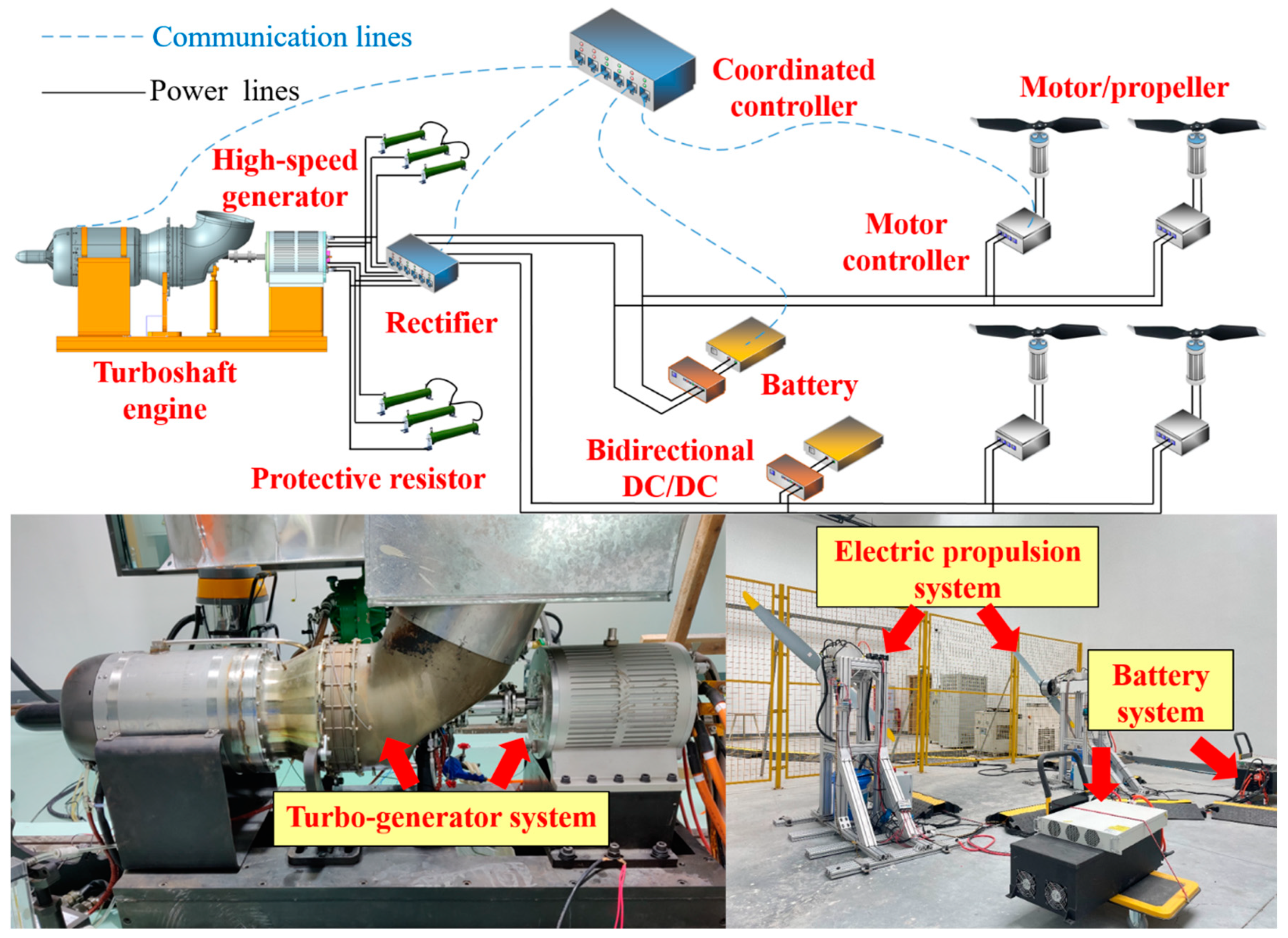
2. Experimental System and Scheme

The 200 kW class series hybrid system in this article mainly includes a turbo-generator system (consists of a turboshaft engine and a high-speed generator), a battery system, an electric propulsion system, a coordination controller, and a microgrid system, as shown in Figure 1. Among them, the turboshaft engine adopts a dual-rotor configuration, with a design power of 240 kW, a gas turbine speed of 46,000 r/min, and a power turbine speed of 21,000 r/min. The high-speed generator uses a permanent magnet synchronous generator (PMSG) with a design power of 240 kW, and its rotor is directly connected to the power turbine through a coupler. The electric propulsion system consists of four identical sets of electric motors and propellers, with each motor having a rated power of 50 kW and a rated speed of 2300 r/min. The battery system includes a lithium-ion battery pack, a battery manage system (BMS), and bidirectional DC/DC, with a battery capacity of 31 Ah, a charge rate of 0.5 C, and a discharge rate of 2 C. The coordination controller is independently designed and developed. Based on the STM32 microcontroller, it is capable of efficiently issuing control commands through a host computer and realizing data transmission through CAN, RS232, and other communication methods, thereby integrating various subcomponents into a centralized control system. The microgrid system adopts a double busbar structure to back up each other, relying on the turbo-generator set to stabilize the DC bus voltage, and the battery system outputs or absorbs electrical power at a fixed value.
The experiment primarily measures the speed of the gas turbine and power turbine (NG and NP), the exhaust temperature of the gas turbine and power turbine outlet (T4 and T5), DC bus voltage, that is, rectifier output voltage (UDC), the operating speed and power consumption of motor/propeller (NM and PM), and the power consumption of load and rectifier (PL and PR). Other measured parameters such as the vibration of the engine/generator and the temperature of motors are primarily used for fault monitoring and protection, which are not subjected to additional analysis. During the experiments, the controllable variables are the throttle ratio of the turboshaft engine, the status and output voltage of the rectifier, the start or stop of the motor/propeller, and their output frequency. Additionally, the controlled variable is the speed of the power turbine. Notably, during the starting process, the rectifier includes two states: uncontrolled rectification and controlled rectification. For the former, the rectifier output voltage is proportional to the input voltage, which is proportional to the speed of the power turbine; for the latter, the rectifier can output DC power with adjustable voltage by controlling the conduction and shutdown of the switching tube [27].

3. Experimental Results and Discussion

In the following part of this article, the starting process and parameter characteristics of the series hybrid aero propulsion system will be analyzed in detail, especially due to the converter required for the PMSG and DC microgrid, which has certain coupling characteristics between the turboshaft engine, the high-speed generator, and the motors/propellers. On this basis, the effects of starting loads and starting methods are investigated through multiple sets of comparative tests, so as to optimize the control strategy of the starting process and ultimately propose the referenced idle state of this type of hybrid system.

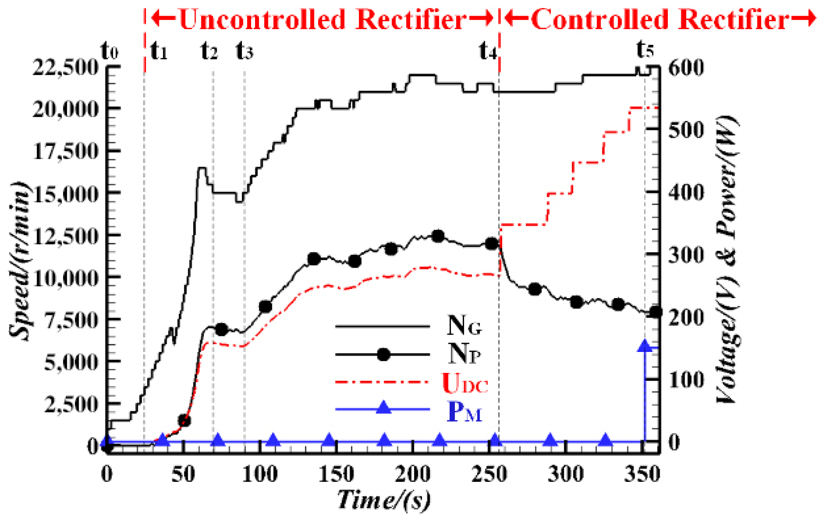
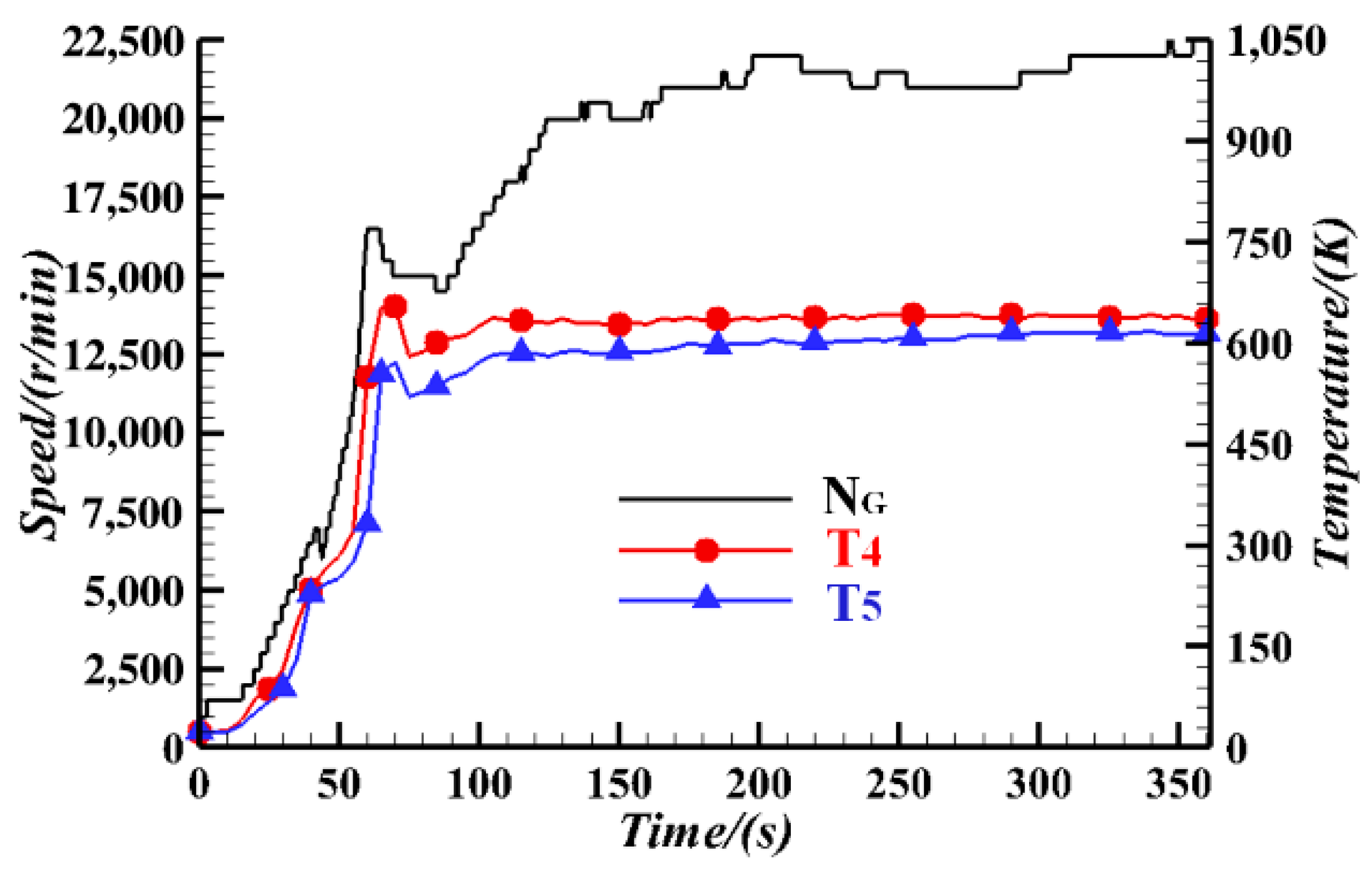
3.1. Analysis of a Typical Starting Process

The idle state of the series hybrid aero propulsion system should require that the speed of the power turbine is not lower than its idle speed, the microgrid system maintains the rated voltage, and the motors/propellers start and run stably at the minimum state. Therefore, the starting process of the series hybrid system is not only based on the starting of the turboshaft engine but also includes three stages: the speed of the gas turbine increasing, controlled rectification intervention, and the electric motors starting. Among them, the speed of the gas turbine can be increased before or after the controlled rectification intervenes, or there can be more than one speed increase process. The main parameter changes during a typical starting process are shown in Figure 2, and the entire starting process took a total of 361.5 s, as follows:
  • The turboshaft engine started:
Taking the starting command issued by the engine control unit (ECU) as the initial moment, after t1 = 29.2 s, the power turbine began to rotate, the generator started producing three-phase AC power, and the rectifier entered an uncontrolled rectification state. When t2 = 69.1 s, the turboshaft engine reached the idle state, with NG = 15,000 r/min, NP = 7000 r/min, and the DC bus voltage UDC = 155 V.
2.
The speed of gas turbine increased:
In order to meet the power demand for stable operation of the microgrid system, NG started to increase at time t3 = 88.7 s. Since the rectifier was still in an uncontrolled rectification state, UDC increased accordingly.
3.
Controlled rectification intervened:
From the moment t4 = 257.1 s, the output voltage of the controlled rectification, that is, UDC, was gradually increasing in the step sequence of “350 V-400 V-450 V-500 V-540 V”. During this stage, the intervention of controlled rectification increased the power consumption on the load side, and NP gradually decreased as the torque increased.
4.
The electric propeller activated:
Once t5 = 351.5 s, the motors were started and ran in the minimum state. At this time, NM = 143 r/min, PM = 150 W, and NP was basically unchanged. It is worth adding that UDC needed to reach 540 V so that the motors could start normally without triggering the undervoltage protection.
The variation in engine exhaust temperatures T4 and T5 with time is shown in Figure 3, taking the changes in NG as a reference. During the starting process of the turboshaft engine, the exhaust temperature first rose and then fell with the changes in NG. After the turboshaft engine reached an idle state, T4 remained basically unchanged, and T5 showed similar temperature characteristics with T4, which was basically stable, although there was a slight rise. The slight increase in exhaust temperature mainly came from the reduction in NP during the controlled rectification stage. Theoretically, it would lead to a decrease in the drop ratio of the power turbine, a decrease in the output power of the power turbine, and a gradual decrease in the difference in temperatures between the inlet and outlet of the power turbine. However, due to the low output power of the turboshaft engine during the starting stage, the reduction in the speed of the power turbine had little impact on the system. This phenomenon represented that during the starting process of the series hybrid aero propulsion system, the impact of the intervention of controlled rectification on the temperature characteristics of the engine is slight.
According to the different states of rectification, the hybrid system during the starting process could be divided into four states: ungenerated, uncontrolled rectification, controlled rectification, and idle state. Some parameter characteristics showed obvious differences in different states. The parameter characteristics under uncontrolled rectification are shown in Figure 4. As NP increased, both UDC and the power consumption of load increased. From the variations in voltage and power given in the figure, it can be seen that UDC and NP show an obvious linear relationship, and there is a square relationship between the power consumption of load and NP. The reason is that before the motor started, the load of the experimental system was only the resistor between the generator and the rectifier, and the power of the purely resistive load had a square relationship with the voltage across it.
However, unlike the power consumption of load, the power consumption of the rectifier did not change significantly during the uncontrolled rectification stage. This is because the rectifier consumed power, including conduction loss and switching loss [28,29,30]. The conduction loss is mainly positively related to the output current [29], but at that time, the rectifier was under no load and did not output current. As for the switching loss, it exists more in the controlled rectification stage, while it is negligible in the uncontrolled rectification state. Therefore, the power consumption of the rectifier was basically not affected by NP and was almost zero, thus making it difficult to measure accurately.
Figure 5 shows the characteristics of each parameter in the controlled rectification state. The voltage value V1 in the figure corresponds to the last moment of the uncontrolled rectification state and is only used as a reference. Due to the switching loss introduced by controlled rectification, the power turbine’s speed at the 350 V voltage level was reduced by approximately 21.7% compared to the uncontrolled rectification state. As the voltage level increased, the power consumption of rectification gradually rose. The main reason is that the switching loss of the power semiconductor device IGBT in the rectifier was positively correlated with the output voltage [30]. The increase in rectification power consumption caused the torque of the turbo-generator set to increase, resulting in a continuous decrease in NP. At a voltage level of 540 V, NP fell to only 64.2% of what it was before the intervention of controlled rectification. This conclusion indicates that the process of controlled rectification would bring about significant power consumption, and the voltage level of controlled rectification had a remarkable impact on NP. According to the analysis of the uncontrolled rectification state mentioned above, it could be explained that the power consumption of load was proportional to the square of NP. Hence, the power consumption of load was inversely related to the microgrid voltage level.
To sum up, during the starting process of the series hybrid aero propulsion system, NP, UDC, and the power consumption of components exhibited mutual coupled characteristics. The definition of the idle state of a hybrid system should comprehensively consider the three indicators of NP, UDC, and electric thruster status, i.e., PM. Therefore, on the basis of the idle state of the turboshaft engine, the speed of the gas turbine needs to be appropriately increased to meet the requirement of NP. In addition, in order to meet the UDC demand, controlled rectification is required. Once the indexes of NP and UDC are met, we could start the electric motors and make them operate in the minimum state, then the starting process can be considered as finished at this time.

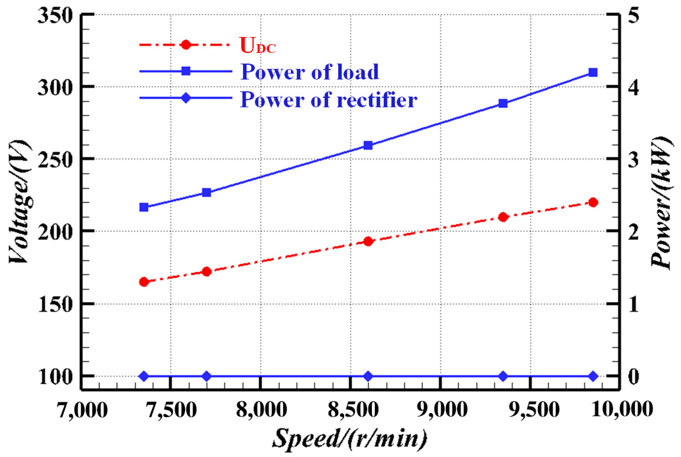
3.2. Optimization of the Starting Process

The 200 kW class series hybrid system in this article adopts a direct connection between the power turbine and generator without reduction gear. For this reason, the rotational inertia of the turbo-generator set is so low that the set is facing the risk of overspeed runaway. Additionally, the establishment of a 540 V DC microgrid involves the AC/DC rectification process. Combined with the power matching problem during the starting process, there is some potential for optimization of the method of controlled rectification. In view of the above two aspects, this paper carried out several sets of comparative tests and reasonably optimized the starting control strategy of a series hybrid aero propulsion system based on the experimental results.
First of all, in view of the risk of overspeed runaway caused by the low rotational inertia of the turbo-generator set, this paper added a variable resistor between the generator and the rectifier. The equivalent rotational inertia of the generator during the starting process would be increased through the power consumption of resistance, thereby achieving the purpose of increasing the rotor torque and reducing the mechanical risk. The typical starting process in the previous section introduced a resistive load with a maximum power of 10 kW. From Figure 2, it can be found that under 10 kW resistance, the idle speed of the power turbine under 540 V steady-state was about 7000 r/min, which is a large safety margin from the design speed of 21,000 r/min. In this situation, the turboshaft engine needed an increase in throttle ratio of 9% to ensure that the progress of controlled rectification would be smooth and effective. In addition, a low speed of the power turbine would also cause a series of problems such as limiting the peak power of the engine and affecting the power density of the generator. Therefore, it is necessary to optimize the design of the starting load.
Based on the above considerations, this article first carried out comparison tests of different starting resistors with maximum power of 10 kW, 6.5 kW, and 3 kW; the results are shown in Figure 6. It can be seen from the figure that NP under the maximum power of the 10 kW, 6.5 kW, and 3 kW resistors are 7000 r/min, 7700 r/min, and 9000 r/min, respectively, and the actual power consumed by the resistances are 2.1 kW, 1.6 kW, and 0.9 kW, respectively. The power turbine’s idle speed can be fitted to the maximum power consumption of the resistive load using the data analysis software, which can be represented by a quadratic polynomial:
n = 24.49 P m 2 604.1 P m + 10,590 ,
where n is the power turbine’s idle speed and Pm is the maximum power consumption of the starting load. According to the above relationship, when the starting load is cancelled, that is, Pm = 0, the estimated idle speed of the power turbine is 10,590 r/min. On this basis, an experiment without a starting resistor was carried out. The idle speed of the power turbine obtained in the test was 10,500 r/min, which was less than 2% of the estimated value. In summary, adding a resistive load between the generator and the rectifier to dissipate power can increase the equivalent rotational inertia of the turbo-generator set during the starting process and realize the adjustment of the idle speed of the power turbine. Due to the mechanical and excitation losses, etc., there is no issue for the 200 kW hybrid aero propulsion system studied in this paper to consider the overspeed protection during the starting process.
Secondly, aiming at the optimization of the AC/DC rectification process of a 540 V DC microgrid, this article carried out experimental research on different strategies of controlled rectification. Figure 7 shows the changes in UDC and NP under the one-step and multistep rectification. It can be seen that although the step sequence of “350 V-400 V-450 V-500 V-540 V” rectification could ensure NP was within a safe range throughout the entire process, the steps are complex, time-consuming, and inefficient. Compared with the rectification using a step sequence to establish the voltage class of the microgrid, the one-step rectification could effectively simplify the experimental procedures and significantly shorten the transient time of NP, and then optimize the total time of the starting process. However, the one-step rectification caused NP to fluctuate by more than 16%. Its minimum speed was 6250 r/min, which was close to the 6000 r/min safe boundary. On the other hand, during the adjustment of the multistep rectification, the overshoot of NP did not exceed 5%. Due to the comprehensive consideration of the duration of time and the overshoot of speed, this article recommends adopting a two-step strategy for controlled rectification. Noteworthy is that the idle speed of the power turbine obtained by one-step and multistep rectification were 7800 r/min and 7500 r/min, respectively, with a difference of about 4%. The analysis suggests that this is due to factors such as incoming flow conditions and resistance temperature drift between different sets of tests, resulting in normal deviations.
Based on the above study results, this article adopted the starting optimization strategy of non-resistance protection and two-step rectification. The optimized starting process is shown in Figure 8. Once the hybrid system was in the uncontrolled rectification state and NG was 15,000 r/min, the two indexes of NP and UDC were 10,500 r/min and 225 V, which were increases of about 50% compared with those before optimization. Under the controlled rectification state, during the two-step loading processes of “400 V-540 V”, NP decreased relatively smoothly. To achieve the power demand of 540 V and maintain an NP of 10,500 r/min, NG needed to be increased to approximately 17,000 r/min, which was 22.7% lower than the value without optimization of about 22,000 r/min, thus reducing unnecessary power losses. Overall, the optimized starting process only took 127.5 s, which was 64.7% shorter than the starting time before optimization. Moreover, the optimized starting control flow was clearer, laying the foundation for the design and implementation of the automatic control law. All in all, when NG was at 17,000 r/min, the motors/propellers could switch on and run stably at the minimum state. This value was only 13.3% higher than its idle speed of 15,000 r/min. Therefore, this article proposes to define the idle state of the 200 kW series hybrid aero propulsion system as follows: (1) NP = 10,500 r/min; (2) UDC = 540 V; (3) PM = 150 W, that is, the minimum state in which the motors can run stably.

4. Conclusions

Combined with the developmental trends of high-speed generators and high-voltage DC microgrids in high-power series hybrid aero propulsion systems, this article carried out research on the starting experiment of a 200 kW class series hybrid aero propulsion system. The coupled characteristics of each component in different states of the hybrid system during the starting process were analyzed in detail. And the optimal design of the starting process was also carried out. The main conclusions are as follows:
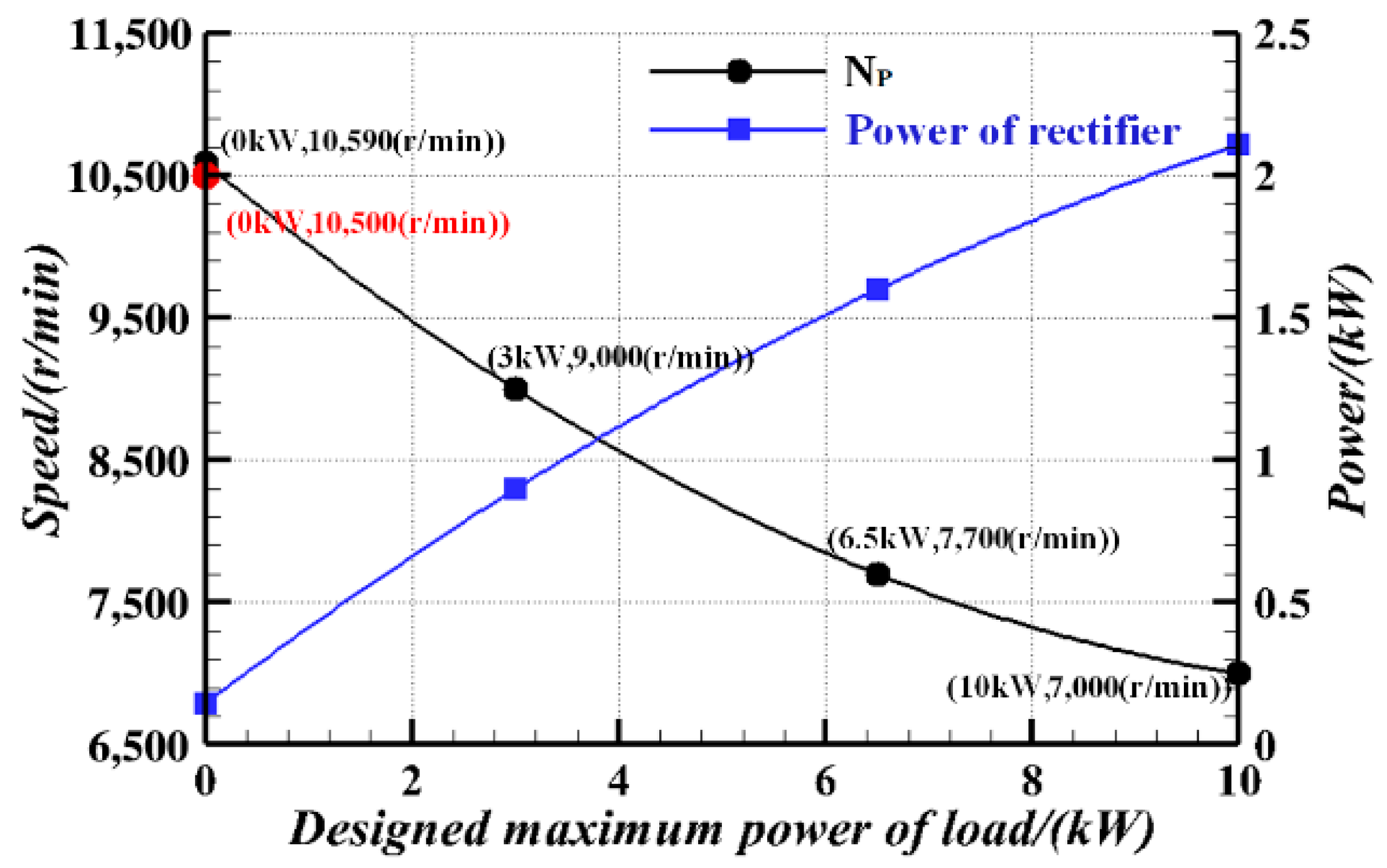
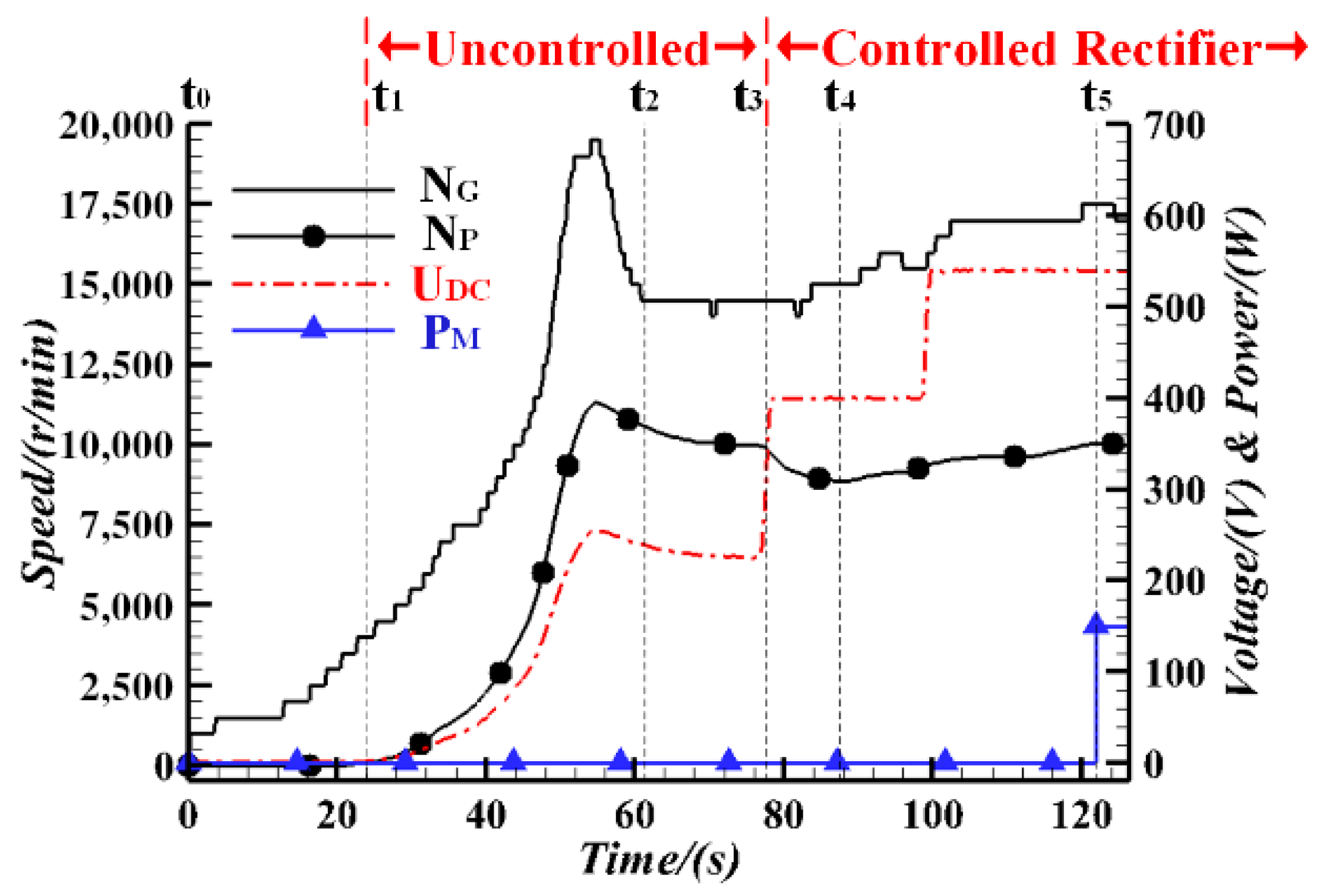
  • The starting process of the series hybrid aero system mainly includes four stages: the turboshaft engine is started, the speed of the gas turbine is increased, controlled rectification intervenes, and the electric propeller is activated. The idle state should be defined with the status of the turbo-generator set (NP), the microgrid (UDC), and the electric motors (PM). For the 200 kW class hybrid propulsion system in this paper, it is suggested to set the idle parameters NP, UDC, and PM as 10,500 r/min, 540 V and 150 W, respectively.
  • Adding resistive loads between the generator and the rectifier could increase the equivalent rotational inertia of the turbo-generator set through the power dissipation in the resistance, thereby realizing the adjustment of the rotational speed in the idle state. In terms of some losses of the turbo-generator set itself, such as mechanical and excitation losses, there is no need to set additional resistors for overspeed protection during the starting phase of the 200 kW class hybrid system in this article.
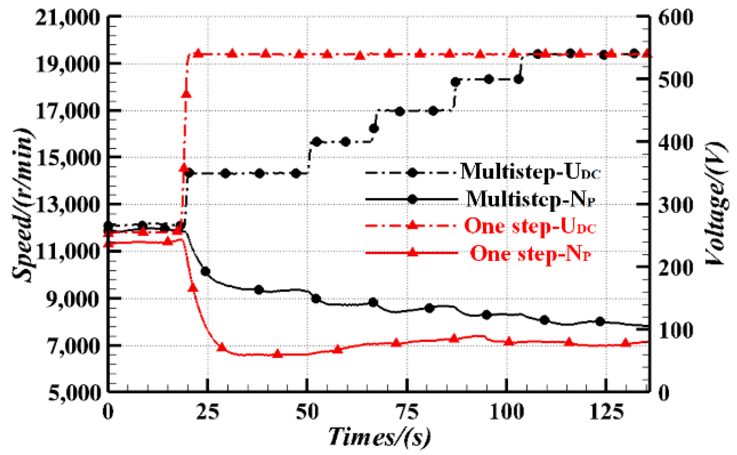
  • Different strategies of controlled rectification in the DC microgrid had an impact on the dynamic characteristics of the power turbine. The one-step method caused NP to fluctuate by 16%, and the multistep method took a longer time. Using a two-step strategy with “400 V-540 V”, the decrease in NP was relatively smooth and the time required was shorter.
  • Based on the optimal starting strategy of no-resistance protection and two-step rectification, the total duration of the starting process after optimization was shortened by 64.7%, NG required in the idle state of hybrid system was reduced by 22.7%, the starting sequence was faster and clearer, and the optimum effects were significant.

Author Contributions

Data curation, M.X.; formal analysis, P.L.; funding acquisition, J.Z.; investigation, M.X., M.L. and B.D.; methodology, P.L.; project administration, J.Z.; software, G.H. and M.X.; supervision, J.Z. and P.L.; writing—original draft, J.Z., G.H. and M.X.; writing—review and editing, M.L., B.D. and P.L. All authors have read and agreed to the published version of the manuscript.

Funding

This research was funded by the National Natural Science Foundation of China, grant number 52276040.

Data Availability Statement

The data that support the findings of this study are available on request from the corresponding author, Po Li, upon reasonable request.

Acknowledgments

The authors wish to express their appreciation to the editors for their rigorous and efficient work and to the reviewers for their helpful suggestions, which greatly improved the quality of this paper.

Conflicts of Interest

The authors declare no conflict of interest.

References

  1. Smruti, S.; Zhao, X.; Konstantinos, K. A review of concepts, benefits, and challenges for future electrical propulsion-based aircraft. Aerospace 2020, 7, 44. [Google Scholar]
  2. Vijesh, M.; Andrew, K.J.; Susan, L. Systems integration framework for hybrid-electric commuter and regional aircraft. Aerospace 2023, 10, 533. [Google Scholar]
  3. De Vries, R.; Brown, M.; Vos, R. Preliminary sizing method for hybrid-electric distributed-propulsion aircraft. J. Aircr. 2019, 56, 2172–2188. [Google Scholar] [CrossRef]
  4. Lents, C.E.; Hardin, L.W.; Rheaume, J.; Kohlman, L. Parallel hybrid gas-electric geared turbofan engine conceptual design and benefits analysis. In Proceedings of the 52nd AIAA/SAE/ASEE Joint Propulsion Conference, Washington, DC, USA, 13–17 June 2016; p. 4610. [Google Scholar]
  5. IATA. Aircraft Technology Roadmap to 2050; IATA: Montreal, QC, Canada, 2019. [Google Scholar]
  6. Kim, H.D.; Felder, J.L.; Tong, M.T.; Berton, J.J.; Haller, W.J. Turboelectric distributed propulsion benefits on the N3-X vehicle. Aircr. Eng. Aerosp. Technol. Int. J. 2014, 86, 558–561. [Google Scholar] [CrossRef]
  7. Welstead, J.; Felder, J.; Guynn, M.; Haller, B.; Tong, M.; Jones, S.; Ordaz, I.; Quinlan, J.; Mason, B. Overview of the NASA STARC-ABL (Rev. B) advanced concept. In Proceedings of the Boeing NASA Electric Aircraft Workshop, Washington, DC, USA, 22 March 2017. [Google Scholar]
  8. Schiltgen, B.T.; Freeman, J. Aeropropulsive interaction and thermal system integration within the ECO-150: A turboelectric distributed propulsion airliner with conventional electric machines. In Proceedings of the 16th AIAA Aviation Technology, Integration, and Operations Conference, Washington, DC, USA, 13–17 June 2016; p. 4064. [Google Scholar]
  9. Papathakis, K.V.; Kloesel, K.J.; Lin, Y.; Clarke, S.; Ediger, J.J.; Ginn, S. Design and development of a 200-kw turbo-electric distributed propulsion testbed. In Proceedings of the 52nd AIAA/SAE/ASEE Joint Propulsion Conference, Salt Lake City, UT, USA, 25–27 July 2016; p. 4611. [Google Scholar]
  10. Dyson, R.W. NASA Electric Aircraft Testbed (NEAT) single-aisle transport air vehicle hybrid electric tail-cone thruster powertrain configuration and test results. In Proceedings of the AIAA/IEEE Electric Aircraft Technologies Symposium, Cincinnati, OH, USA, 9–11 July 2018; p. 5004. [Google Scholar]
  11. European Commission. Flightpath 2050: Europe’s vision for aviation-report of the high level group on aviation research. In Report of the High Level Group on Aviation Research; European Commission: Luxembourg, 2011. [Google Scholar]
  12. Whurr, J.; Hart, J. A Rolls-Royce perspective on concepts and technologies for future green propulsion systems. Green Aviat. 2016, 1, 95. [Google Scholar]
  13. Anton, D.F. eAircraft: Hybrid-Elektrische Antriebe für Luftfahrzeuge, 14th ed.; Tag der Deutschen Luft-und Raumfahrtregionen: Potsdam, Germany; Siemens AG: Berlin, Germany, 2019. [Google Scholar]
  14. Dan, T. EcoPulse leads charge to hybrid power: French partners outline ambitious plans for distributed propulsion system as next step towards more-electric aircraft. In Flight International; Reed Business Information: New York, NY, USA, 2019. [Google Scholar]
  15. Wang, L.; Gao, H.; Wang, P. The development of hybrid electric propulsion technology in Russia. Aerosp. Power 2019, 6, 40–44. [Google Scholar]
  16. Mei, Q.; Jin, H.; Shen, Y. Design and integrated verification of fuel-electric hybrid power system. Aerosp. Power 2021, 1, 39–42. [Google Scholar]
  17. Vimala, N.; Kishore, P.D. Review–sub-idle performance of aero gas turbine engine. In Proceedings of the ASME 2017 Gas Turbine India Conference, Bangalore, India, 7–8 December 2017; p. 4609. [Google Scholar]
  18. Golovanov, D.; Gerada, D.; Sala, G.; Degano, M.; Trentin, A.; Connor, P.H.; Xu, Z.; La Rocca, A.; Galassini, A.; Tarisciotti, L.; et al. 4-MW class high-power-density generator for future hybrid-electric aircraft. IEEE Trans. Transp. Electrif. 2021, 7, 2952–2964. [Google Scholar] [CrossRef]
  19. Cotton, I.; Nelms, A.; Husband, M. Higher voltage aircraft power systems. IEEE Aerosp. Electron. Syst. Mag. 2008, 23, 25–32. [Google Scholar] [CrossRef]
  20. Perullo, C.; Trawick, D.; Armstrong, M.; Tai, J.C.M.; Mavris, D.N. Cycle selection and sizing of a single-aisle transport with the Electrically Variable Engine (EVE) for fleet level fuel optimization. In Proceedings of the 55th AIAA Aerospace Sciences Meeting, Grapevine, TX, USA, 9–13 January 2017; p. 1923. [Google Scholar]
  21. Eryilmaz, I.; Pachidis, V. Turbine thermomechanical modelling during excessive axial movement and overspeed. Aeronaut. J. 2019, 260, 248–264. [Google Scholar] [CrossRef]
  22. Hao, B.; Qu, T.; Jing, Y. Modeling of aero-engine starting process based on rising rate of rotating speed. In Proceedings of the 33rd Chinese Control and Decision Conference (CCDC), Kunming, China, 22–24 May 2021; pp. 7011–7015. [Google Scholar]
  23. Eryilmaz, I.; Pachidis, V. A design approach for controlled blade-off in overspeeding turbines. Eng. Fail. Anal. 2022, 138, 106323. [Google Scholar] [CrossRef]
  24. Loder, D.C.; Bollman, A.; Armstrong, M.J. Turbo-electric distributed aircraft propulsion: Microgrid architecture and evaluation for ECO-150. In Proceedings of the 2018 IEEE Transportation Electrification Conference and Expo, Long Beach, CA, USA, 13–15 June 2018; pp. 550–557. [Google Scholar]
  25. Lei, T.; Kong, D.; Wang, R.; Li, W.; Zhang, X. Evaluation and optimization method for power systems of distributed electric propulsion aircraft. Acta Aeronaut. Asronautica Sin. 2021, 42, 624047. [Google Scholar]
  26. Guddanti, B.; Choi, J.; Illindala, M.S.; Roychowdhury, R. Effect of endogenous failure events on the survivability of turboelectric distributed propulsion system. IEEE Trans. Ind. Appl. 2022, 58, 224–232. [Google Scholar] [CrossRef]
  27. Wang, Z.; Liu, J. Power Electronics, 5th ed.; China Mechine Press: Beijing, China, 2009; pp. 101–126. [Google Scholar]
  28. Brombach, J.; Lücken, A.; Nya, B.; Johannsen, M.; Schulz, D. Comparison of different electrical HVDC-architectures for aircraft application. In Proceedings of the Electrical Systems for Aircraft, Railway and Ship Propulsion (ESARS), Bologna, Italy, 16–18 October 2012; pp. 1–6. [Google Scholar]
  29. Sadey, D.J.; Taylor, L.; Beach, R. Proposal and development of a high voltage variable frequency alternating current power system for hybrid electric aircraft. In Proceedings of the 14th International Energy Conversion Engineering Conference, Salt Lake City, UT, USA, 25–27 July 2016; p. 4928. [Google Scholar]
  30. Jansen, R.; Bowman, C.; Jankovsky, A. Sizing power components of an electrically driven tail cone thruster and a range extender. In Proceedings of the 16th AIAA Aviation Technology, Integration, and Operations Conference, Washington, DC, USA, 13–17 June 2016; p. 3766. [Google Scholar]
Figure 1. Experimental platform of 200 kW class series hybrid aero propulsion system.
Aerospace 11 00063 g001
Figure 2. Typical starting process.
Aerospace 11 00063 g002
Figure 3. Variation in exhaust gas temperature in typical starting process.
Aerospace 11 00063 g003
Figure 4. Parameter characteristics in uncontrolled rectification state.
Aerospace 11 00063 g004
Figure 5. Parameter characteristics in controlled rectification state.
Aerospace 11 00063 g005
Figure 6. Comparison of different starting loads.
Aerospace 11 00063 g006
Figure 7. Comparison of different starting methods.
Aerospace 11 00063 g007
Figure 8. Starting process after optimization.
Aerospace 11 00063 g008
Disclaimer/Publisher’s Note: The statements, opinions and data contained in all publications are solely those of the individual author(s) and contributor(s) and not of MDPI and/or the editor(s). MDPI and/or the editor(s) disclaim responsibility for any injury to people or property resulting from any ideas, methods, instructions or products referred to in the content.

