Article

Design and Shape Monitoring of a Morphing Wing Trailing Edge

1
Department of Smart Structures and Structural Health Monitoring, Aircraft Strength Research Institute of China, Xi’an 710065, China
2
Chinese Aeronautical Establishment, Beijing 100027, China
3
State Key Laboratory for Strength and Vibration of Mechanical Structures, School of Aerospace, Xi’an Jiaotong University, Xi’an 710049, China
*
Authors to whom correspondence should be addressed.
Aerospace 2023, 10(2), 127; https://doi.org/10.3390/aerospace10020127
Submission received: 11 December 2022 / Revised: 24 January 2023 / Accepted: 28 January 2023 / Published: 30 January 2023
(This article belongs to the Section Aeronautics)

Abstract

:
The morphing wing trailing edge is an attractive aviation structure due to its shape-adaptive ability, which can effectively improve the aerodynamic performance of an aircraft throughout the whole flight. In this paper, a mechanical solution for a variable camber trailing edge (VCTE) based on a multi-block rotating rib is proposed. Parametric optimizations are conducted to achieve the smooth and continuous deformation of the morphing rib. A prototype is designed according to the optimized results. In addition, the deformations of the trailing edge are monitored via an indirect method using a fiber Bragg grating (FBG) sensor beam. Finally, ground tests are performed to investigate the morphing capacity of the VCTE and the shape monitoring ability of the proposed method. Our results indicate that a maximum deflection range from 5° upward to 15° downward can be obtained for the VCTE and the indirect sensing system can satisfactorily monitor the deformation of the trailing edge.

1. Introduction

Aircraft wings provide most of the aerodynamic lift and control force during flight. The shape of the wing directly affects the aerodynamic performance of an aircraft [1]. The design of an aircraft wing is therefore of great importance. Usually, a specific wing can only provide good aerodynamic performances in several specific flight conditions, and its shape may not be optimal in other conditions. Thus, in order to improve aerodynamic performance throughout the flight envelope, it is essential to change the shape of the wing. Conventional devices, such as flaps or slats, are used to modify the shape of aircraft wings. However, minimal benefit is obtained due to limited changes to the overall geometry [2]. Compared with traditional wings, morphing wings possess good shape-adaptive ability and have become a vital characteristic for future aircraft [3].
The continuous camber morphing of the wing trailing edge is one of the most attractive morphing strategies, which can effectively change the lift to drag the coefficient of the wing. As a result, fuel consumption and air pollutant emissions can be reduced by maintaining the optimal wing shape according to different flight environments and missions. For large and medium-sized aircraft, the variable camber trailing edge (VCTE) was confirmed to effectively improve aerodynamic performance by 2% during the whole flight. Consequently, about 3% of fuel consumption and USD 10 million were saved per year for short-haul air transportation [4].
One basic aspect of the morphing wing is flexible skin, which allows large deformation while keeping the aerodynamic surface smooth. Several potential flexible skin concepts have been proposed, such as sliding skin [5], elastomeric skin [6,7], deformable cellular structures [8,9], and corrugated skin [10,11,12]. Another key aspect is deformable structure or mechanisms. Some deformable structures/mechanisms for the VCTE have also been proposed, which can be divided into two strategies according to the deformation principle. The first type is the compliant solution depending on the elastic deformation of the material or structure itself. Some smart materials have been adopted as actuators in this type of VCTE, such as shape memory alloys (SMA) and macro-fiber composites (MFC) or piezoelectric materials [13,14,15]. The compliant VCTE is more suitable for small aircraft and unmanned aerial vehicles (UAVs) [16,17,18]. For example, as a typical compliant solution, corrugated structures have been extensively explored as morphing wings for micro-air vehicles (MAVs) [19,20,21] and UAVs [22]. Despite compliant morphing structures having the advantage of being lightweight with a large deformation ability, they are unapplicable for large commercial aircraft because of their limited bearing capacity when deforming.
The second type is the mechanical solution based on rigid hinge connections. Comparatively, mechanical solutions adopt general aircraft materials and traditional driving modes such as motor drive, which may be more applicable to large aircraft. However, research focused on the mechanical solution for the VCTE for large aircraft is limited [23,24,25]. For example, Pecora et al. [25] proposed a finger-like adaptive trailing edge to improve the aerodynamic performance of aircraft during cruise with a small deflection range of 5° upward and downward. However, this limited deflection was inadequate for high-lift performance during takeoff and landing. Consequently, the researchers subsequently developed a finger-like wing flap which could be deployed with camber morphing at the same time [26]. Despite a greater deflection range being achieved, the corresponding complexity and weight of the wing were also increased. Thus, further investigation is necessary for VCTE design aiming at smooth and continuous large deformations to achieve optimal performance in cruise and other challenging phases.
As mentioned above, morphing wings always experience large deformations during flight, which are complex and continuous. Therefore, a shape monitoring system is quite important for optimal deformation control of the morphing structures. At present, traditional shape sensing systems usually adopt strain gages or visual deformation measurement, which are not suitable for the on-line deformation monitoring of morphing wings because of their large weight or size, poor transmission ability of the measured data, and low endurance [27]. Fiber Bragg grating (FBG) sensors possess many prominent advantages, such as high sensitivity, a light weight, high endurance, and corrosion and electromagnetic interference resistance [28,29,30]. The monitoring method based on FBG sensors has developed rapidly in recent years and has been widely used in aerospace structures [31,32,33]. The sensing ability of FBGs has been validated through a series of applications [34,35,36]. With regard to morphing wings, FBGs have been used for shape sensing in some research wherein the sensors were directly bonded or embedded into the skin [37,38]. For example, Nazeer et al. [39] developed a multimodal shape sensing system to estimate the deformed shape of a morphing wing section by bonding FBG sensors on the surface of the wing. He et al. [40] proposed a polyvinyl chloride (PVC)-reinforced silicone substrate embedded with FBGs for the shape monitoring of the morphing wing. However, the bonded or embedded methods damage the structural integrity of the skin and the smoothness of the wing shape, which are crucial to the performance of morphing wings. Moreover, once the sensor is damaged, it is difficult to remove and repair it. Thus, the monitoring method based on FBG sensors needs to be further developed.
In order to achieve continuous camber morphing of the wing trailing edge for large aircraft, a mechanical VCTE based on a multi-block rotating rib is proposed, and an indirect shape monitoring system is designed to evaluate the deformation accuracy. This paper is organized as follows: The structural design of the VCTE is detailed in Section 2. The shape monitoring method is described in Section 3. The experiments, results, and discussion are presented in Section 4. Finally, the work is concluded in Section 5.

2. Variable Camber Trailing Edge

2.1. Mechanical Solution

In this paper, research was carried out to develop a VCTE aimed at improving wing aerodynamic performance in the whole flight envelope. The reference aircraft was the aerodynamic validation model (AVM) proposed by the Chinese Aeronautical Establishment (CAE) [41]. In this initial design phase of VCTE, for the sake of simplicity, the chord length was assumed constant and equal to 30% of the mean aerodynamic chord (MAC). The reference airfoil section was selected at 30% in the spanwise direction of the fuselage. The airfoil shapes before and after deformation are shown in Figure 1, where the airfoil camber morphing angle β is defined between the two straight lines connecting the rotation center and the tip in the non-morphed and morphed configurations. The target deflections were first analyzed via CFD-based optimization to improve the aerodynamic efficiency of the wing during cruise, and a range of 1.5° upward to 1.7° downward was given [42]. Considering that the trailing edge should also meet the requirements of large deflection during takeoff and landing, the values of the β angle were finally determined to be included in the range [−2°: +15°], where negative values indicated upward morphing.
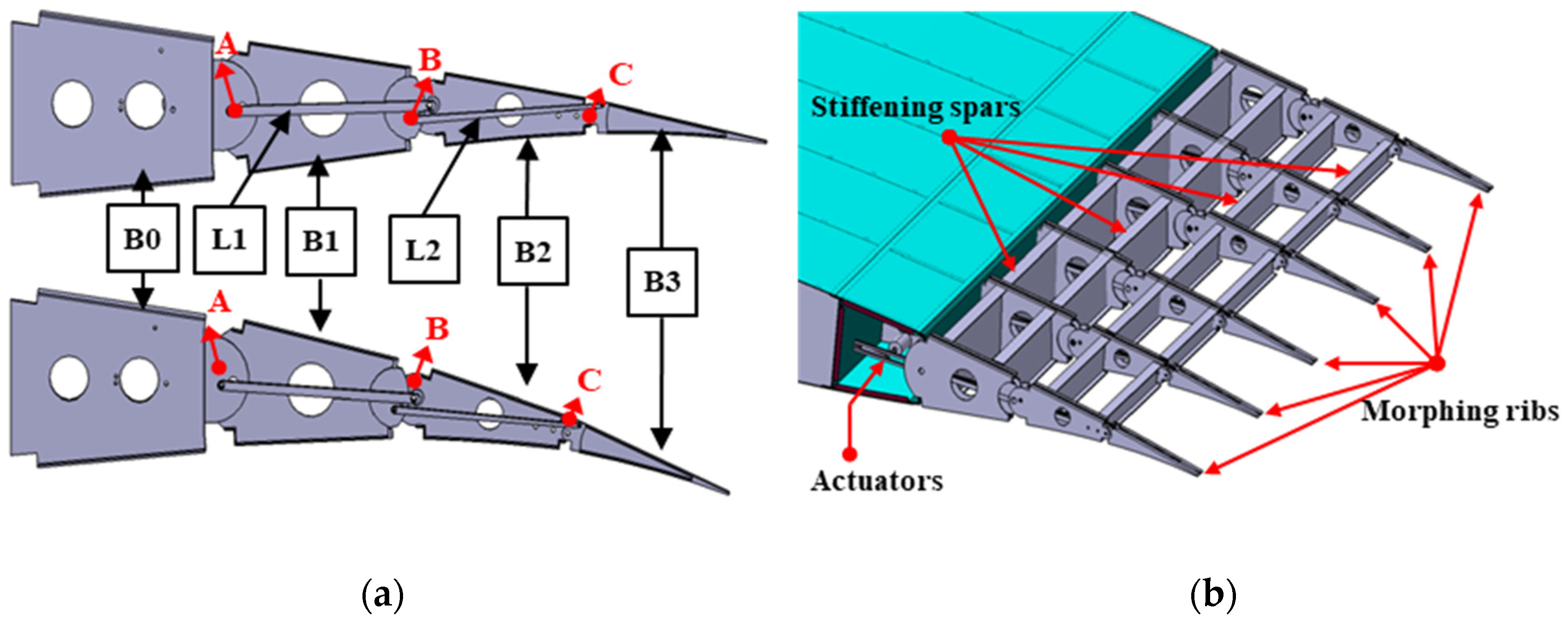
In order to enable the trailing edge to deform from the baseline shape to the target shape, a multi-block rotating mechanism was developed for the rib of the VCTE. A previous study showed that a three-segmented system was enough to approximate the curvature of the morphing trailing edge [43]. Thus, the rib is segmented into three morphing blocks (B1, B2, and B3) and a fixed block (B0), as shown in Figure 2a.
It can be observed that the fixed block B0 and the morphing blocks B1, B2, and B3 are hinged to each other at three points (A, B, and C) of the airfoil camber line, which correspond to 70%, 80%, 90% of the MAC, respectively. Moreover, block B0 is connected to non-adjacent block B2 through a link L1, and block B1 is connected to non-adjacent block B3 through a link L2. In this way, these elements generate a single degree-of-freedom (DOF) mechanism. If one of the blocks is fixed, the shape does not change. Further, if any of the blocks are actuated, all the others follow the movement accordingly. The overall deflection of the rib is achieved by the relative rotation between the blocks, while the airfoil thickness distribution is approximately unchanged.
Such morphing ribs are arranged along the span of the trailing edge and connected with each other via transversal stiffening spars in Figure 2b. The trailing edge deforms once these ribs are subjected to external actuations from the driving systems. When the ribs change to a desired shape, they are frozen by locking the driving system to make the whole trailing edge remain stable under external aerodynamic loads. The working principle of the driving system is detailed in Section 2.3.

2.2. Optimization of Morphing Rib

For the single-DOF mechanism of the morphing rib, the motion law is uniquely defined when the positions of the linking rod hinges are determined. In order to ensure that the trailing edge can deform from the baseline to the target shape continuously, the hinge positions should be optimized. This process requires the establishment of the equivalent mechanism model for the kinematic chain and the solution of the hinge positions definition problem.
With regard to the established morphing rib in this paper, the positions of the hinges (A, B, and C) along the camber line are the input data of the problem. The positions of link L1 (DF) and link L2 (EG) in Figure 3 are the unknown variables which need to be determined.
Firstly, a kinematics analysis of the four-bar linkage ADFB is carried out. Referring to Figure 3, the angle between the coordinate axes X1 and X2 is θ1, and the angles between the links AD and DF; DF and BF; and AB and BF are θ2, θ3, and θ4, respectively. The counterclockwise direction is defined as positive. LAD, LDF, LBF, and LAB are the lengths of the four linkages. According to the rotation matrix method, the transformation matrix K12 is obtained by converting the coordinates of the point A in coordinate system X1Y1 to X2Y2:
K 12 = [ c o s ( θ 1 ) s i n ( θ 1 ) L A D s i n ( θ 1 ) c o s ( θ 1 ) 0 0 0 1 ]
Similarly, the following transformation matrixes K23, K34, and K41 are obtained by converting the coordinates of point A in coordinate system X2Y2 to the others:
K 23 = [ c o s ( θ 2 ) s i n ( θ 2 ) L D F s i n ( θ 2 ) c o s ( θ 2 ) 0 0 0 1 ]
K 34 = [ c o s ( θ 3 ) s i n ( θ 3 ) L B F s i n ( θ 3 ) c o s ( θ 3 ) 0 0 0 1 ]
K 41 = [ c o s ( θ 4 ) s i n ( θ 4 ) L A B s i n ( θ 4 ) c o s ( θ 4 ) 0 0 0 1 ]
When the coordinates are finally converted back to coordinate system X1Y1, the node coordinates (xA1, yA1) of point A remain unchanged as follows:
[ x A 1 y A 1 1 ] = K 41 K 34 K 23 K 12 [ x A 1 y A 1 1 ]
K 41 K 34 K 23 K 12 = E
The motion law of the four-bar linkage ADBF can be obtained by substituting Equations (1)–(4) into Equation (6) as expressed in Equation (7). Similarly, the kinematics analysis of the four-link EBGC is carried out and expressed as Equation (8).
{ θ 1 + θ 2 + θ 3 + θ 4 = 0 ( L A D c o s ( θ 2 + θ 3 ) L F D c o s ( θ 3 ) + L F B ) c o s ( θ 4 ) s i n ( θ 4 ) ( L A D s i n ( θ 2 + θ 3 ) L F D s i n ( θ 3 ) ) + L A B = 0 s i n ( θ 4 ) ( c o s ( θ 3 ) ( L A D c o s ( θ 2 ) L F D ) s i n ( θ 3 ) s i n ( θ 2 ) L A D + L F B ) + c o s ( θ 4 ) ( s i n ( θ 3 ) ( L A D c o s ( θ 2 ) L F D ) + c o s ( θ 3 ) s i n ( θ 2 ) L A D ) = 0
{ θ 5 + θ 6 + θ 7 + θ 8 = 0 ( L B E c o s ( θ 6 + θ 7 ) L G E c o s ( θ 7 ) + L C G ) c o s ( θ 8 ) s i n ( θ 8 ) ( L B E s i n ( θ 6 + θ 7 ) L G E s i n ( θ 7 ) ) + L B C = 0 s i n ( θ 8 ) ( c o s ( θ 7 ) ( L B E c o s ( θ 6 ) L G E ) s i n ( θ 7 ) s i n ( θ 6 ) L B E + L C G ) + c o s ( θ 8 ) ( s i n ( θ 7 ) ( L B E c o s ( θ 6 ) L G E ) + c o s ( θ 7 ) s i n ( θ 6 ) L B E ) = 0
Since points B, E, and F are all located on block B1, the rotation angles of the linkages BF (∆θ4) and BE (∆θ5) are the same during the mechanism movement:
Δ θ 4 = Δ θ 5
Finally, the equivalent mechanism model of the kinematic chain in Figure 3 can be expressed as Equations (7)–(9). Once the hinge positions of the links DF and EG are defined, the motion low of the morphing rib can be determined. Therefore, the optimization problem of the link positions should be solved to achieve the target deformation of the morphing rib continuously.
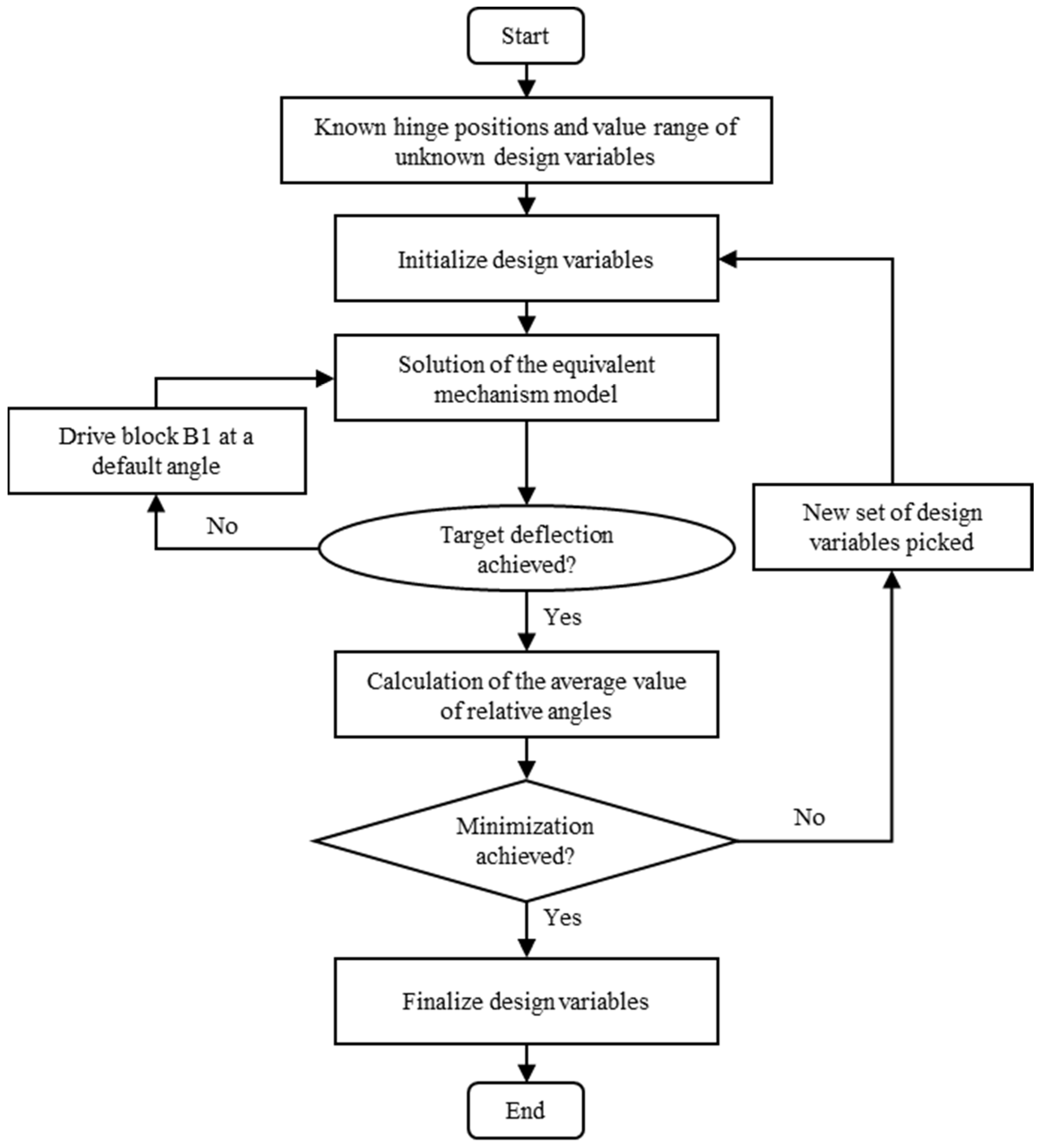
In this paper, a parametric optimization method based on the genetic algorithm was established to identify the proper positions of links DF and EG. Figure 4 shows a flowchart of the optimization process.
Firstly, the value range of the unknown design variables, namely the positions of unknown points (D, E, F, and G), was determined according to the profile of the airfoil. An initial mechanism model was established with the known hinge positions along the camber line and a set of hypothetical design variables.
Then, block B1 (link AB in the model) was assumed to rotate at a small angle (the default change is 0.01° per iteration in the program). The new coordinates of each point in the model after rotation were obtained by solving the equivalent mechanism model using the Matlab fsolve function. The maximum deflection angle that could be achieved with this hypothesis model was simulated. If the results met the target deflection, the positions of unknown points were preliminarily determined.
Next, in order to deform as smoothly as possible, the optimization objective was introduced to minimize the average value of the relative angles between moving blocks. Once the model determined in the previous step was evaluated as not optimal, a next set of hypothesis design variables would be picked for the mechanism motion simulation. In this way, the optimized positions of the hinge points could be finally solved.
According to the optimization process, the final equivalent mechanism model of the rib was obtained as shown in Figure 5. In this figure, the red line represents the initial state of the rib, and the blue line represents the deformation state. The deformation downward to the target position (+15°) is shown in Figure 5a, and the upward deformation (−2°) is shown in Figure 5b. It can be observed that the camber lines after upward and downward deformation, described by points A′, B′, C′, and point H′ (wing tip), were relatively smooth based on the optimization rib design.

2.3. Design of the Prototype

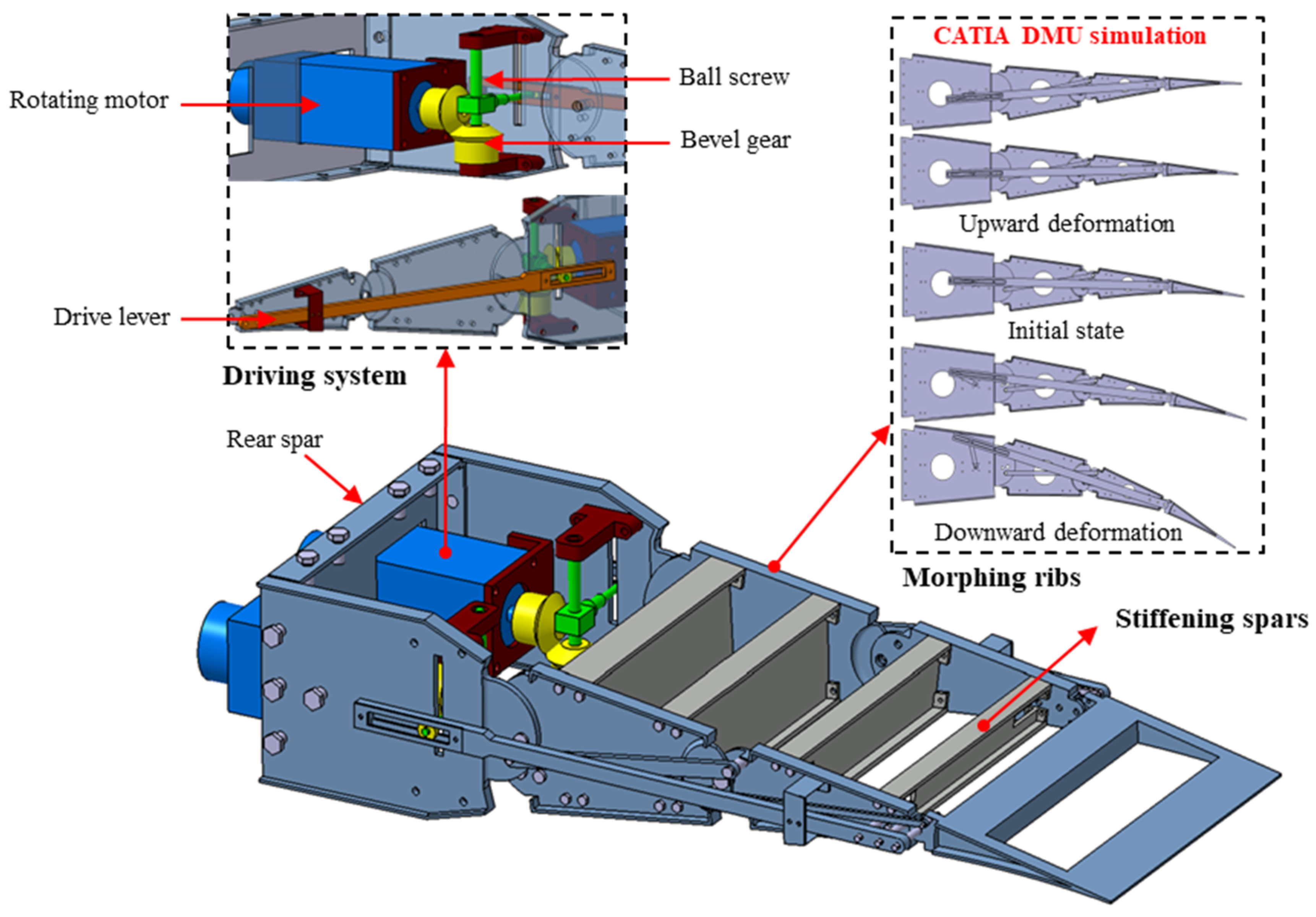
For the preliminary structural verification, a scaled prototype was designed as a typical wing box of a VCTE. The chordwise length extending from the fixed part to the tip section is 0.649 m and the spanwise length is 0.244 m. The overall structural components of the scaled VCTE are presented in Figure 6.
As can be seen in Figure 6, the VCTE prototype consists of a pair of morphing ribs, a distributed driver system, a rear spar, and several stiffening spars. The rear spar is connected to the fixed part of the wing to support the whole structure. The consecutive blocks are hinged together and the hinge positions are set according to the results in Section 2.2. The driving system is made of a couple of motors, bevel gears, ball screws, and levers. The system is connected to block B2 of each morphing rib. When the motor works, the rotating ball nut is driven up or down along the screw through the bevel gear and ball screw; then, the morphing rib is actuated by the lever connecting its block and the ball nut. In this way, the actuation torque from the actuator transmits to the morphing rib. When the motor stops working, the bevel gear pair can lock itself, leaving the rib in a specific position. Meanwhile, the bevel gear also acts as a reducer in this actuation kinematic. In addition, the kinematic simulation of the rib mechanism was carried out by CATIA DMU. It was achieved by defining the connections between the components of the morphing rib in CATIA. The results show that a smooth and continuous deformation with no linkage interference can be obtained along upward and downward directions, as shown in the picture to the right of Figure 6. The bottom picture shows the mechanical design of VCTE structure as detailed below, with a slot on the block allowing the movements of the ball nut.

3. Shape Monitoring Method

3.1. Sensor System Based on FBG Sensors

In order to optimize aerodynamic performance in real time, it is necessary for the VCTE to monitor the deformed shape accurately. However, it is difficult to measure deformation directly because the morphing trailing edge herein has a complicated mechanism and large deformations. In this section, an indirect FBG-based sensor system was designed to monitor the shape of the trailing edge, as shown in Figure 7. A simple cantilever beam is placed inside the VCTE structure. The sensor beam is made of aluminum alloy with an elastic modulus and Poisson’s ratio of 70 Gpa and 0.33, respectively. One end of the beam is fixed on the non-deformed part of the VCTE at the position coinciding with the rotating shaft, and the other end is connected to the wing tip. There are several holes in the spars for placing the shape sensor beam and allowing sliding movements. When the trailing edge deforms, the shape sensor beam follows the deflection freely as it morphs through different shapes. Consequently, the morphing behavior of the VCTE can be identified with the deformation of the sensor beam. In this way, the deformed shape of the trailing edge is indirectly monitored.
Detailed information about the shape sensor beam is also indicated in Figure 7b. It has a length of 310.0 mm, a width of 15.0 mm, and a height of 1.0 mm. Five FBG sensors are glued to the lower surface of the beam. During the morphing process, the shape information was translated into strain information and properly modulated with the help of the optical fiber on the sensor beam and the demodulator. Then, these strain values were converted back into an approximation of the actual shape through the computer integrated with the deformation monitoring algorithm. Finally, the real-time deformation of the VCTE could be evaluated.

3.2. Monitoring Algorithm

By arranging the FBG sensors along the axial direction on the surface of the beam, various segments were defined between each adjacent point of strain measurement. Once the strain values were obtained, the shape of the sensor beam was evaluated by an analytical model commonly called KO theory [44], which was proposed by William L. Ko to predict the deformation of aerospace structures. The method has been demonstrated to be efficient for the shape monitoring of wing structures [45,46]. The algorithm in KO theory is described in detail as follows.
In the case of pure bending deformation or bending as the main deformation mode, the relation between the strain ε(x) and the bending deflection ω(x) of the beam with equal thickness can be expressed as:
ε ( x ) = c d 2 ω ( x ) d x 2
where c is the vertical distance between the surface bonded with FBGs and the middle surface of the beam. It is defined as:
c = ε t , i ε t , i ε b , i h
where εt,i and εb,i are the strain measured on the upper and lower surface of point i, respectively, and h is the thickness of the beam.
Generally, εt,i and εb,i are approximately equal in absolute value during bending; then, c is expressed as:
c = h 2
Assuming that the strain changes linearly when the beam is bent, the strain change of the ith section can be obtained by:
ε ^ ( x ) = ε i ( ε i ε i + 1 ) ( x x i ε ) Δ l i
where εi and εi+1 are the strain values at the starting point and the ending point of the ith section, respectively.
The distance between both ends of the ith section is defined as:
Δ l i = x i + 1 x
The rotation angle of the ith section is defined as:
tan θ ( x ) = 2 x i ε x ε ( x ) h d x + tan θ i ε
The bending deflection is computed by:
ω ( x ) = 2 x i ε x x i ε x ε ( x ) h d x d x + x i ε x tan θ i ε d x + ω i ε
Under the bending condition for the unilateral fixed beam, the deflection and the angle at the first measurement point is defined as boundary conditions:
θ 1 ε = 0 , ω 1 ε = 0
Equation (16) is derived as:
ω ( x ) = 2 x i ε x x i ε x ε ( x ) h d x d x
As shown above, the deflection at any location of the first section can be calculated, and then the whole deformation curve of the beam is obtained by repeating the above process.

4. Experiments and Discussion

4.1. Prototype and Demonstration Platform of VCTE

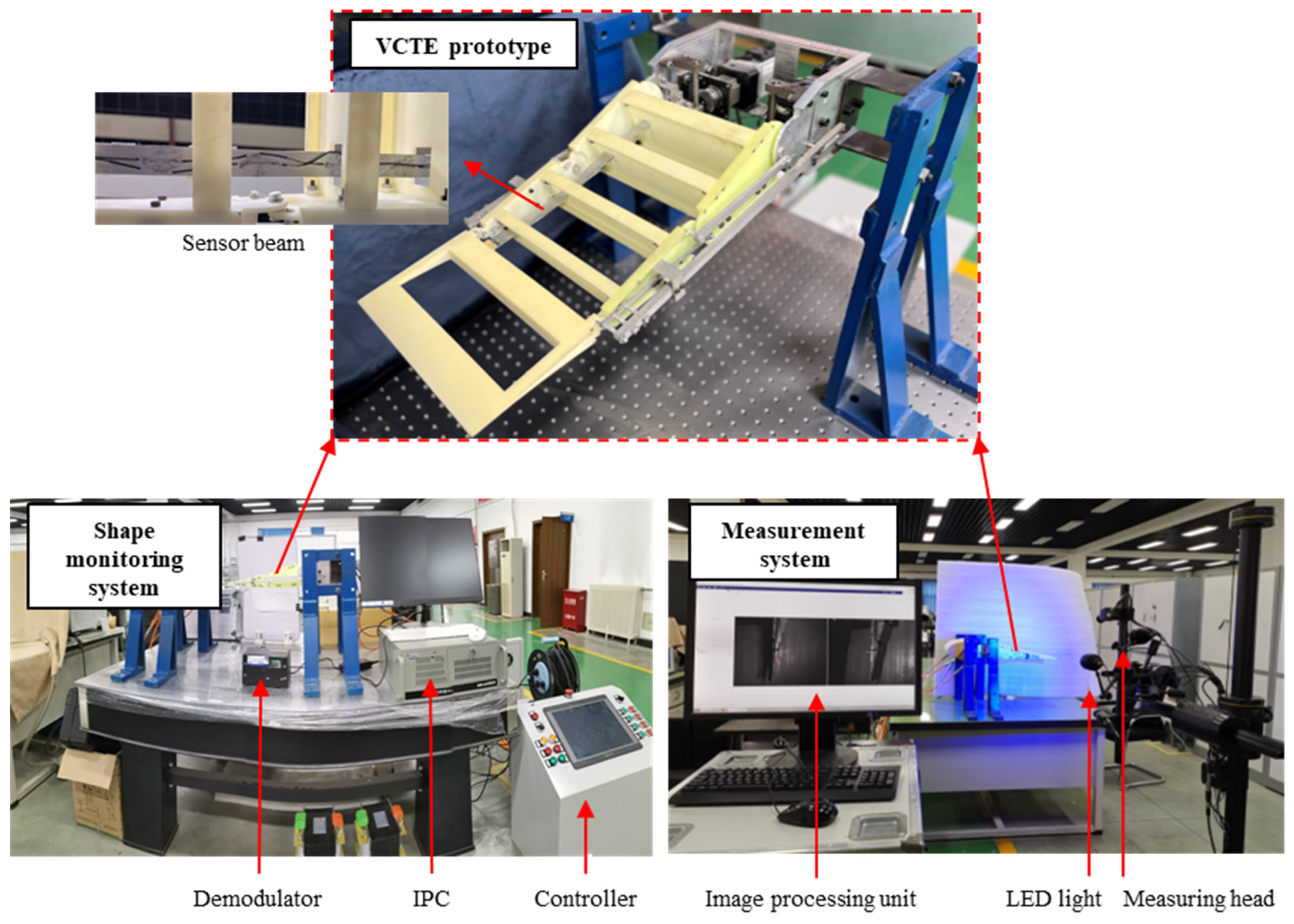
In order to verify the design and shape monitoring method of the VCTE proposed in this paper, a ground demonstration platform was established as in Figure 8, which included a VCTE prototype, a shape monitoring system, and a three-dimensional (3D) non-contact optical measurement system.
The details of the VCTE prototype are also presented in Figure 8. The blocks of morphing ribs were fabricated by 3D printing and connected by steel links and joints, allowing them to deform continuously. Two servo motors were distributed inside the wing on both sides to provide the driving force of the morphing ribs. The shape monitoring system mainly consisted of a sensor beam with FBG sensors, a demodulator, and an industrial personal computer (IPC) with integrated control and monitoring software. The type of demodulator was Micron Optics SM-125, which was used to receive the reflected FBG signals from the sensor beam. Then, the signals were converted to strain data and transmitted to the computer. LabVIEW software was developed to calculate the deflection of the trailing edge in real time. Moreover, a 3D speckle full strain field measurement system ARAMIS 3D 6M was used to evaluate the deformation accordingly. The measurement system consisted of a measuring head (two cameras), an LED light, and an image processing unit. The measurement system took pictures of the prototype with a binocular camera and then collected the three-dimensional coordinates of the reference point arranged on the prototype. The deformation of the prototype could be obtained depending on the changes in the coordinates of reference points. The strain fields were not calculated since we were only concerned with the deflection angle of the VCTE.

4.2. Functionality Test

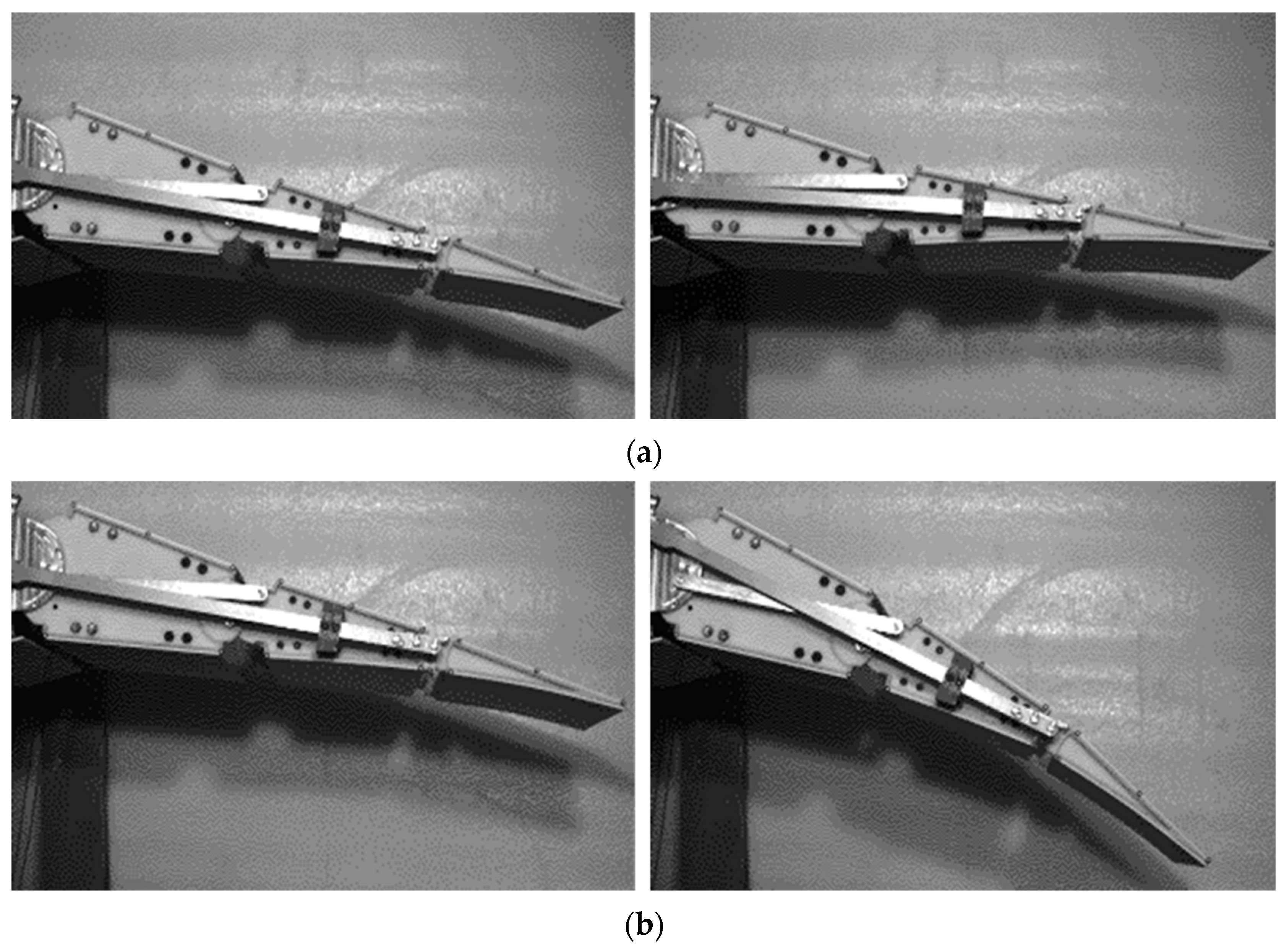
In order to verify the proposed design method, the prototype of the VCTE was actuated to deflect up and down in cyclic motion. Figure 9 shows photos of the prototype at its initial and deformed state via a camera. It can be observed that the designed trailing edge can achieve large deformation in both upward and downward directions.
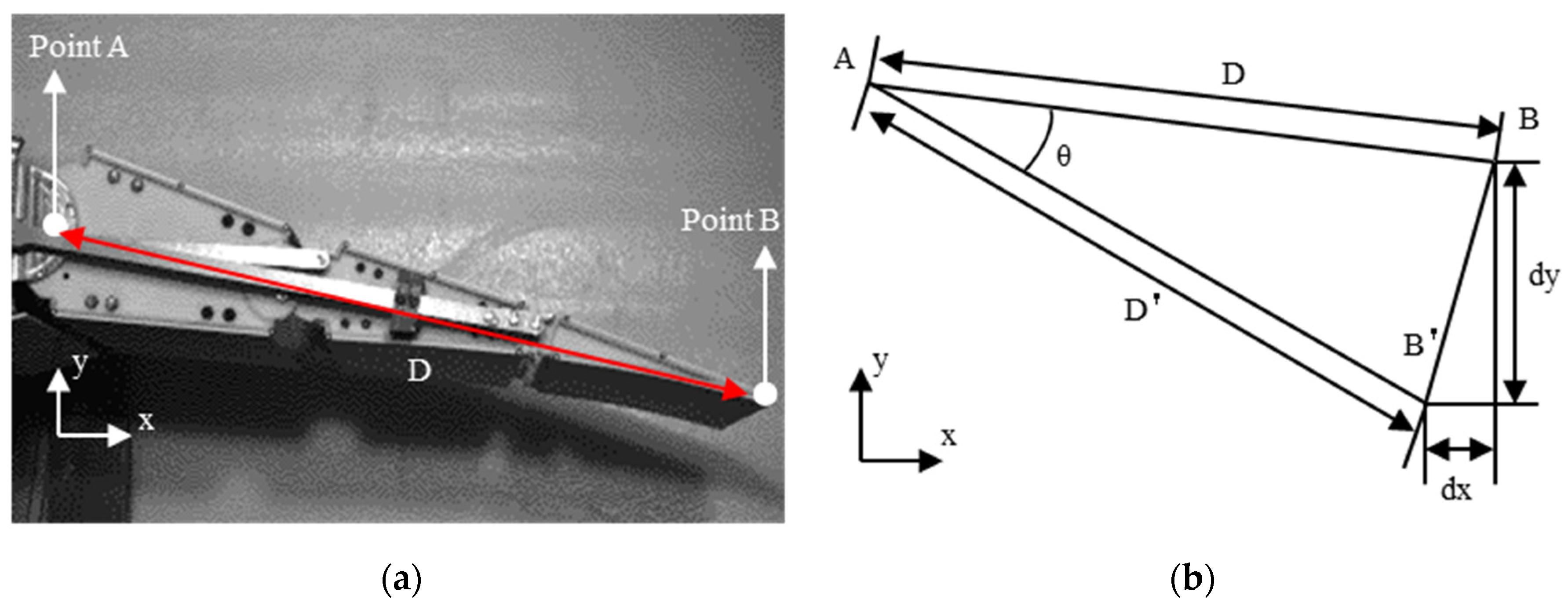
Meanwhile, different reference points for optical measuring were arranged on the surface of the morphing rib, especially in the position of the rotating shaft at the root and the wingtip point, as shown in Figure 10a. By tracking the change in coordinates of the wingtip (point B) and the wing root (point A) during the morphing process, the distance between the two points could be obtained; then, the deflection angle of the VCTE could be calculated by the law of cosines, as described in Figure 10b.
Based on the simplified model in Figure 10b, the deflection angle can be calculated according to Equation (19).
θ = arccos ( ( D 2 + D 2 ( d x 2 + d y 2 ) ) / ( 2 D D ) )
where D and D′ are the distances between point A and B, respectively, before and after deformation.
During the experiment, the VCTE was driven up and down to the maximum deflection, while the initial and final states were tracked by the optical measurement system to measure the deformed shapes. This process was repeated twice, and the experimental results are shown in Table 1. It is worth noting that the prototype could achieve an upward deflection of more than 5°, which exceeded the deformation requirements (−2°) of the initial design value. Meanwhile, the target downward deflection (+15°) was also realized. This means that the experimental results coincide well with the theoretical results. The above results verify the proposed method of the VCTE in the paper and demonstrate a potential ability for deformation in a wider range.

4.3. Shape Monitoring Experiment

The stability of the shape monitoring system was checked on this platform via a sensor temperature drift experiment. The VCTE was held by the fixed motor at the initial state (0°), and the strain values of the FBG sensors were simultaneously set to zero. Then, the strain data was continuously collected for 15 min in the same environmental conditions. The real-time shapes of the trailing edge were calculated based on the strain values. Figure 11a shows the monitored deformation angles at different times. It can be observed that the maximum angle was less than 0.06°, which was quite close to the actual state (0°). These results indicate that the shape monitoring system was stable and could be used for the deformation estimation of the VCTE.
The VCTE was subsequently actuated to different positions, and the real-time shapes were monitored. The monitoring results obtained by the FBG sensor system were compared to the corresponding results measured by the optical measurement system. Figure 11b indicates that the monitored results are in good agreement with the optical measurements. It is shown that the maximum relative error was only 4.03% for each deformed state. Because of the inevitable mechanism clearance caused by assembly and manufacturing errors, the deflection measured by the indirect method may be slightly offset from the actual deflection. The shape monitoring results can be provided for the control system to minimize the error of deformation, allowing the VCTE to be adjusted to the optimal state.

5. Conclusions

In this study, the structural design and shape monitoring methods of a variable camber trailing edge (VCTE) were presented. The ground tests were performed to validate the morphing capacity and shape monitoring ability of the proposed methods for VCTE. The main conclusions are as follows:
  • According to the target deflections of the reference airfoil, the proposed parametric optimization design method of the multi-segment morphing rib can provide a solution for VCTE structure which can effectively realize smooth and continuous deformation.
  • The functionality test indicated that the VCTE prototype could achieve a maximum deflection range from 5° upward to 15° downward, which satisfied the design requirements.
  • An indirect shape monitoring method-based FBG sensor beam was proposed and the real-time deflection angles of the VCTE were evaluated by using the measured strain values and the KO algorithm.
  • The shape monitoring method was experimentally verified via comparison with measured deflections using optical equipment. The maximum relative error was less than 4.03%, showing good agreement at each deformed state.
In summary, this study presents a mechanical design method for VCTE structure and establishes an indirect shape monitoring method for morphing wings which can achieve accurate large deformation measurements without damaging structural integrity. It may be applied not only to the VCTE proposed in this paper but also to other morphing wing structures for accurate shape control. Further research is necessary to investigate the design method of the morphing skin, which needs to satisfy the large deformation of the trailing edge. Further, the influence of sensor environmental sensitivity should be analyzed for the shape monitoring method to achieve the accurate deformation prediction of the morphing wing in complicated flight environments.

Author Contributions

Conceptualization, X.S. (Xintong Shi) and Y.Y.; methodology, X.S. (Xintong Shi) and Z.W.; software, X.S. (Xintong Shi) and S.Z.; validation, X.S. (Xintong Shi), Z.W. and S.Z.; formal analysis, X.S. (Xintong Shi) and Z.W.; investigation, X.S. (Xintong Shi) and Z.W.; resources, Y.Y. and X.S. (Xiasheng Sun); data curation, S.Z.; writing—original draft preparation, X.S. (Xintong Shi); writing—review and editing, Y.Y., X.S. (Xiasheng Sun) and W.F.; visualization, X.S. (Xiasheng Sun) and W.F.; supervision, X.S. (Xiasheng Sun) and W.F. All authors have read and agreed to the published version of the manuscript.

Funding

This research received no external funding.

Institutional Review Board Statement

Not applicable.

Informed Consent Statement

Not applicable.

Data Availability Statement

Data are contained within the article.

Conflicts of Interest

The authors declare no conflict of interest.

References

  1. Ameduri, S.; Concilio, A. Morphing Wings Review: Aims, Challenges, and Current Open Issues of a Technology. Proc. Inst. Mech. Eng. Part C J. Mech. Eng. Sci. 2020, 0, 095440622094442. [Google Scholar] [CrossRef]
  2. Concilio, A.; Dimino, I.; Pecora, R. SARISTU: Adaptive Trailing Edge Device (ATED) Design Process Review. Chin. J. Aeronaut. 2021, 34, 187–210. [Google Scholar] [CrossRef]
  3. Barbarino, S.; Bilgen, O.; Ajaj, R.M.; Friswell, M.I.; Inman, D.J. A Review of Morphing Aircraft. J. Intell. Mater. Syst. Struct. 2011, 22, 823–877. [Google Scholar] [CrossRef]
  4. Pecora, R. Multi-modal morphing wing flaps for next generation green regional aircraft: The CleanSky challenge. In Proceedings of the Smart Materials, Adaptive Structures and Intelligent Systems, San Antonio, TX, USA, 10–12 September 2018. [Google Scholar]
  5. Bishay, P.L.; Kok, J.S.; Ferrusquilla, L.J.; Espinoza, B.M.; Heness, A.; Buendia, A.; Zadoorian, S.; Lacson, P.; Ortiz, J.D.; Basilio, R.; et al. Design and Analysis of MataMorph-3: A Fully Morphing UAV with Camber-Morphing Wings and Tail Stabilizers. Aerospace 2022, 9, 382. [Google Scholar] [CrossRef]
  6. Parancheerivilakkathil, M.S.; Haider, Z.; Ajaj, R.M.; Amoozgar, M. A Polymorphing Wing Capable of Span Extension and Variable Pitch. Aerospace 2022, 9, 205. [Google Scholar] [CrossRef]
  7. Ahmad, D.; Ajaj, R.M.; Amoozgar, M. Elastomer-Based Skins for Morphing Aircraft Applications: Effect of Biaxial Strain Rates and Prestretch. Polym. Test. 2022, 113, 107655. [Google Scholar] [CrossRef]
  8. Chang, L.; Shen, X.; Dai, Y.; Wang, T.; Zhang, L. Investigation on the Mechanical Properties of Topologically Optimized Cellular Structures for Sandwiched Morphing Skins. Compos. Struct. 2020, 250, 112555. [Google Scholar] [CrossRef]
  9. Bubert, E.A.; Woods, B.K.S.; Lee, K.; Kothera, C.S.; Wereley, N.M. Design and Fabrication of a Passive 1D Morphing Aircraft Skin. J. Intell. Mater. Syst. Struct. 2010, 21, 1699–1717. [Google Scholar] [CrossRef]
  10. Golzar, M.; Ghabezi, P. Corrugated Composite Skins. Mech. Compos. Mater. 2014, 50, 137–148. [Google Scholar] [CrossRef]
  11. Liu, T.-W.; Bai, J.-B.; Li, S.-L.; Fantuzzi, N. Large Deformation and Failure Analysis of the Corrugated Flexible Composite Skin for Morphing Wing. Eng. Struct. 2023, 278, 115463. [Google Scholar] [CrossRef]
  12. Ghabezi, P. Rectangular and Triangular Corrugated Composite Skins. Fiber. Polym. 2018, 19, 435–445. [Google Scholar] [CrossRef]
  13. Bishay, P.L.; Finden, R.; Recinos, S.; Alas, C.; Lopez, E.; Aslanpour, D.; Flores, D.; Gonzalez, E. Development of an SMA-Based Camber Morphing UAV Tail Core Design. Smart Mater. Struct. 2019, 28, 075024. [Google Scholar] [CrossRef]
  14. Bilgen, O.; Friswell, M.I. Piezoceramic Composite Actuators for a Solid-State Variable-Camber Wing. J. Intell. Mater. Syst. Struct. 2014, 25, 806–817. [Google Scholar] [CrossRef]
  15. Henry, A.C.; Molinari, G.; Rivas-Padilla, J.R.; Arrieta, A.F. Smart Morphing Wing: Optimization of Distributed Piezoelectric Actuation. AIAA J. 2019, 57, 2384–2393. [Google Scholar] [CrossRef]
  16. Paradies, R.; Ciresa, P. Active Wing Design with Integrated Flight Control Using Piezoelectric Macro Fiber Composites. Smart Mater. Struct. 2009, 18, 035010. [Google Scholar] [CrossRef]
  17. Bilgen, O.; Kochersberger, K.B.; Inman, D.J.; Ohanian, O.J., III. Novel, bidirectional, variable-camber airfoil via macro-fiber composite actuators. J. Aircr. 2010, 47, 303–314. [Google Scholar] [CrossRef]
  18. Jia, S.; Zhang, Z.; Zhang, H.; Song, C.; Yang, C. Wind Tunnel Tests of 3D-Printed Variable Camber Morphing Wing. Aerospace 2022, 9, 699. [Google Scholar] [CrossRef]
  19. Lian, Y.; Broering, T.; Hord, K.; Prater, R. The Characterization of Tandem and Corrugated Wings. Prog. Aeronaut. Sci. 2014, 65, 41–69. [Google Scholar] [CrossRef]
  20. Au, L.T.K.; Phan, H.V.; Park, S.H.; Park, H.C. Effect of Corrugation on the Aerodynamic Performance of Three-Dimensional Flapping Wings. Aerosp. Sci. Technol. 2020, 105, 106041. [Google Scholar] [CrossRef]
  21. Hovius, N.; Leacox, A.; Turowski, J. Recent Volcano–Ice Interaction and Outburst Flooding in a Mars Polar Cap Re-Entrant. Icarus 2008, 197, 24–38. [Google Scholar] [CrossRef]
  22. Hoa, S.; Abdali, M.; Jasmin, A.; Radeschi, D.; Prats, V.; Faour, H.; Kobaissi, B. Development of a New Flexible Wing Concept for Unmanned Aerial Vehicle Using Corrugated Core Made by 4D Printing of Composites. Compos. Struct. 2022, 290, 115444. [Google Scholar] [CrossRef]
  23. Bartley-Cho, J.D.; Wang, D.P.; Martin, C.A.; Kudva, J.N.; West, M.N. Development of High-Rate, Adaptive Trailing Edge Control Surface for the Smart Wing Phase 2 Wind Tunnel Model. J. Intell. Mater. Syst. Struct. 2004, 15, 279–291. [Google Scholar] [CrossRef]
  24. Şahin, H.L.; Yaman, Y. Synthesis, Analysis, and Design of a Novel Mechanism for the Trailing Edge of a Morphing Wing. Aerospace 2018, 5, 127. [Google Scholar] [CrossRef] [Green Version]
  25. Pecora, R.; Concilio, A.; Dimino, I.; Amoroso, F.; Ciminello, M. Structural Design of an Adaptive Wing Trailing Edge for Enhanced Cruise Performance. In Proceedings of the 24th AIAA/AHS Adaptive Structures Conference, San Diego, CA, USA, 4 January 2016. [Google Scholar]
  26. Pecora, R. Morphing Wing Flaps for Large Civil Aircraft: Evolution of a Smart Technology across the Clean Sky Program. Chin. J. Aeronaut. 2021, 34, 13–28. [Google Scholar] [CrossRef]
  27. Ma, Z.; Chen, X. Fiber Bragg Gratings Sensors for Aircraft Wing Shape Measurement: Recent Applications and Technical Analysis. Sensors 2018, 19, 55. [Google Scholar] [CrossRef] [Green Version]
  28. Floris, I.; Adam, J.M.; Calderón, P.A.; Sales, S. Fiber Optic Shape Sensors: A comprehensive review. Opt. Lasers Eng. 2021, 139, 106508. [Google Scholar] [CrossRef]
  29. Gherlone, M.; Cerracchio, P.; Mattone, M. Shape Sensing Methods: Review and Experimental Comparison on a Wing-Shaped Plate. Prog. Aerosp. Sci. 2018, 99, 14–26. [Google Scholar] [CrossRef]
  30. Zheng, Z.; Lu, J.; Liang, D. Load-Identification Method for Flexible Multiple Corrugated Skin Using Spectra Features of FBGs. Aerospace 2021, 8, 134. [Google Scholar] [CrossRef]
  31. Guo, H.; Xiao, G.; Mrad, N.; Yao, J. Fiber Optic Sensors for Structural Health Monitoring of Air Platforms. Sensors 2011, 11, 3687–3705. [Google Scholar] [CrossRef]
  32. Kahandawa, G.C.; Epaarachchi, J.; Wang, H.; Lau, K.T. Use of FBG sensors for SHM in aerospace structures. Photonic Sens. 2012, 2, 203–214. [Google Scholar] [CrossRef]
  33. Lee, J.-R.; Ryu, C.-Y.; Koo, B.-Y.; Kang, S.-G.; Hong, C.-S.; Kim, C.-G. In-Flight Health Monitoring of a Subscale Wing Using a Fiber Bragg Grating Sensor System. Smart Mater. Struct. 2003, 12, 147–155. [Google Scholar] [CrossRef]
  34. Kim, S.-W.; Kang, W.-R.; Jeong, M.-S.; Lee, I.; Kwon, I.-B. Deflection Estimation of a Wind Turbine Blade Using FBG Sensors Embedded in the Blade Bonding Line. Smart Mater. Struct. 2013, 22, 125004. [Google Scholar] [CrossRef]
  35. Li, H.; Zhu, L.; Sun, G.; Dong, M.; Qiao, J. Deflection Monitoring of Thin-Walled Wing Spar Subjected to Bending Load Using Multi-Element FBG Sensors. Optik 2018, 164, 691–700. [Google Scholar] [CrossRef]
  36. Nicolas, M.; Sullivan, R.; Richards, W. Large Scale Applications Using FBG Sensors: Determination of In-Flight Loads and Shape of a Composite Aircraft Wing. Aerospace 2016, 3, 18. [Google Scholar] [CrossRef] [Green Version]
  37. Nazeer, N.; Groves, R.M.; Benedictus, R. Assessment of the Measurement Performance of the Multimodal Fibre Optic Shape Sensing Configuration for a Morphing Wing Section. Sensors 2022, 22, 2210. [Google Scholar] [CrossRef] [PubMed]
  38. Sun, G.; Wu, Y.; Li, H.; Zhu, L. 3D Shape Sensing of Flexible Morphing Wing Using Fiber Bragg Grating Sensing Method. Optik 2018, 156, 83–92. [Google Scholar] [CrossRef]
  39. Nazeer, N.; Wang, X.; Groves, R.M. Sensing, Actuation, and Control of the SmartX Prototype Morphing Wing in the Wind Tunnel. Actuators 2021, 10, 107. [Google Scholar] [CrossRef]
  40. He, Y.; Zhu, L.; Sun, G.; Meng, F.; Song, Y. Fiber Brag Grating Monitoring of a Morphing Wing Based on a Polyvinyl Chloride Reinforced Silicone Substrate. Opt. Fiber Technol. 2019, 50, 145–153. [Google Scholar] [CrossRef]
  41. Zhong, M.; Zheng, S.; Wang, G.; Hua, J.; Gebbink, R. Correlation Analysis of Combined and Separated Effects of Wing Deformation and Support System in the CAE-AVM Study. Chin. J. Aeronaut. 2018, 31, 429–438. [Google Scholar] [CrossRef]
  42. Li, C.P.; Qian, Z.S.; Sun, X.S. The trailing edge deformation matrix aerodynamic design for the long-range civil aircraft variable camber wing. Acta Aeronaut. Astronaut. Sin. 2023, 44, 127335. [Google Scholar] [CrossRef]
  43. Diodati, G.; Ricci, S.; De Gaspari, A.; Huvelin, F.; Dumont, A.; Godard, J.L. Estimated performance of an adaptive trailing-edge device aimed at reducing fuel consumption on a medium-size aircraft. In Proceedings of the Industrial and Commercial Applications of Smart Structures Technologies, San Diego, CA, USA, 29 March 2013. [Google Scholar]
  44. Ko, W.L.; Richards, W.; Tran, V.T. Displacement Theories for In-Flight Deformed Shape Predictions of Aerospace Structures; Technical Report; NASA Dryden Flight Research Center: Edwards, CA, USA, 2007.
  45. Jutte, C.V.; Ko, W.L.; Stephens, C.A.; Bakalyar, J.A.; Richards, W.L.; Parker, A.R. Deformed Shape Calculation of a Full-Scale Wing Using Fiber Optic Strain Data from a Ground Loads Test; Technical Report; NASA Dryden Flight Research Center: Edwards, CA, USA, 2011.
  46. Klotz, T.; Pothier, R.; Walch, D.; Colombo, T. Prediction of the Business Jet Global 7500 Wing Deformed Shape Using Fiber Bragg Gratings and Neural Network. Results Eng. 2021, 9, 100190. [Google Scholar] [CrossRef]
Figure 1. Non-morphed and morphed shape of airfoil.
Aerospace 10 00127 g001
Figure 2. Mechanical solution of VCTE: (a) sketch of multi-block rotating rib; (b) overall arrangement.
Aerospace 10 00127 g002
Figure 3. Equivalent mechanism model of kinematic chain.
Aerospace 10 00127 g003
Figure 4. Flowchart of the optimization process for the morphing rib.
Aerospace 10 00127 g004
Figure 5. Deformation of the optimized morphing rib mechanism: (a) 15° downward; (b) 2° upward.
Aerospace 10 00127 g005
Figure 6. Schematic of the VCTE prototype.
Aerospace 10 00127 g006
Figure 7. FBG-based sensor beam: (a) sensor beam installation inside the VCTE; (b) mechanical design of shape sensor beam.
Aerospace 10 00127 g007
Figure 8. Demonstration platform of the VCTE.
Aerospace 10 00127 g008
Figure 9. Photos of the VCTE prototype before and after deformation: (a) upward deformation; (b) downward deformation.
Aerospace 10 00127 g009
Figure 10. Principle of optical measurement: (a) reference points on VCTE; (b) simplified model of optical measurement.
Aerospace 10 00127 g010
Figure 11. Results of shape monitoring experiments: (a) monitored deflections change over time (at initial state); (b) shape monitoring results and the optical measurements of the VCTE.
Aerospace 10 00127 g011
Table 1. Theoretical and actual deformations of the VCTE.
Theoretical
Deflection (°)
MeasurementsActual
Deflection (°)
Error (%)
dx (mm)dy (mm)D′(mm)D (mm)
−540.09−6.94431.91431.98−5.397.8
39.76−6.90431.91−5.357.0
15−104.7042.13428.5415.070.5
−105.0042.28428.5515.110.7
Disclaimer/Publisher’s Note: The statements, opinions and data contained in all publications are solely those of the individual author(s) and contributor(s) and not of MDPI and/or the editor(s). MDPI and/or the editor(s) disclaim responsibility for any injury to people or property resulting from any ideas, methods, instructions or products referred to in the content.