Stored angular momentum management is a routine operation that most spacecraft must perform to maintain fully usable momentum exchange actuators. Typical mission planning has to take into account this task for correct platform management, and its execution shall be scheduled, commanded from the ground or automatically triggered when certain thresholds are reached. However, particularly in the last case, the angular momentum management may interfere with other primary spacecraft operations or payload activities. This is notably true in the case stored momentum dumping is executed with a dedicated and separate system mode, which cannot guarantee the concurrent execution of the primary mission schedule. In fact, the higher power consumption, the lower pointing or maneuvering performance, the constraints in the system modes, or other system level limitations may prevent the spacecraft from being operated in nominal or payload modes while the momentum exchange actuators are being unloaded.
Small spacecraft with limited power budget, with reduced control authority, or with operative requirements leaving a short time to conduct dedicated momentum management operations are dramatically affected by this problem. However, larger space systems or spacecraft with fewer system-level constraints may benefit from autonomous stored angular momentum management integrated with the main control loop. Indeed, the increased space segment autonomy is a strong asset for any space mission, having the platform management and the nominal house-keeping tasks embedded with the primary operations, and reducing the workload for the ground segment. In this way, ground support with the associated costs can be more focused and dedicated to mission-critical phases, more easily enabling the realization of complex space missions.
The angular momentum stored in a spacecraft is mainly due to momentum exchange actuators, which exploit the conservation of angular momentum law to produce internal torque. Thus, momentum exchange actuators cannot exchange net angular momentum with the external environment, but they produce control torque by exchanging internal angular momentum with the spacecraft’s main body. This can be achieved by putting a mass in rotation and generating reaction torques, as in reaction wheels or control moment gyros (CMGs). In both cases, there exists a maximum momentum capacity that the rotors can hold, and it is commonly related to the maximum angular rate that the electric motor driving the rotor can sustain for a given inertia of the actuator assembly. From the maximum momentum capacity, it is possible to compute for how long a certain torque can be borne before reaching the maximum rotation speed, which is called the saturation speed. In fact, the angular momentum stored in momentum exchange actuators evolves over time because of external torque and control actions. Secular terms, as well as asymmetric control torques, may lead to momentum accumulation or momentum build-up. When the saturation condition is reached, the actuator cannot provide any more torque in that direction, and its stored angular momentum is dumped out. This operation is denoted as stored momentum dumping or actuator unloading or desaturation, and it is performed exploiting devices that can exchange angular momentum with the surrounding environment (e.g., magnetic torquers and thrusters). These secondary actuators provide a net external torque that is capable of counteracting the internal reaction torque due to the momentum unloading (i.e., rotor braking).
This paper proposes a method to autonomously manage the stored angular momentum in attitude control systems (ACSs) by integrating the momentum dumping functions with the main control loop. The continuous control of the stored momentum level enables spacecraft missions without the need for dedicated momentum dumping phases, increasing the system autonomy and facilitating complex and prolonged space operations to be carried out without constant ground support. Without loss of generality, the study focused on spacecraft with reaction wheels as the primary actuation system. Concerning the secondary actuators for angular momentum dumping, the spacecraft is considered to be equipped with magnetic torquers or magnetorquers. Despite the proposed method being theoretically applicable to satellites with thrusters, the low throttleability, the fuel consumption, and the spurious forces on the center of mass make them unsuitable for the proposed integrated application. Moreover, magnetic management of stored angular momentum can be easily applied to a broader group of spacecraft, from nano-satellites to very large space systems, and the magnetic momentum dumping is well established and effective in current spacecraft technologies [
1].
Spacecraft attitude control has been known and studied since the early ages of space exploration. Indeed, despite the first few spacecraft only being launched into ballistic trajectories with uncontrolled or passively stabilized rotational motion, in 1959, the unmanned Luna-3 Soviet space probe had the world’s first three-axis attitude control system to be activated while taking photos of the far side of the Moon [
2]: spacecraft attitude dynamics are too fast or too complicated to be manually controlled, either from ground or onboard. Thus, vast literature on spacecraft attitude control systems is available and well consolidated [
3,
4,
5], especially when angular momentum exchange actuators are used [
6,
7,
8,
9]. Researchers have addressed the magnetic attitude control of spacecraft in low-Earth orbits (LEOs) since the late 1970s. Stickler and Alfriend [
10] set a milestone in this field, defining a method based on the use of averaged models that is extremely efficient in stabilizing the attitude of momentum-biased spacecraft. This work highlighted the excellent properties of magnetic attitude control in generating a dissipative action. In fact, it has been extensively and effectively applied for initial spacecraft angular rate dissipation (i.e., detumbling) or nutation damping. These applications have been deeply studied by numerous scientists [
11,
12,
13,
14], and they have been successfully applied in real operative missions [
15,
16]. Moreover, in recent years, with the advent of small satellite platforms and cubesats, the usage of magnetic attitude control has become even more frequent and interesting for the scientific community [
17,
18,
19,
20,
21]. Among all these studies, the application of magnetic torques for angular momentum dumping was studied by Camilo and Markley [
22]; then, it was applied to a specific mission scenario [
23,
24]. The problem of integrating the momentum dumping with attitude control was studied by Lovera [
1], who proposed a controller based on periodic
and
to improve the classical cross-product control law [
22] when applied to a zero-momentum inertially pointing spacecraft. Later, Trégouët et al. [
25] studied a static input allocation controller for reaction wheels’ desaturation using magnetorquers.
This study departs from the latter two contributions dealing with integrated magnetic momentum management and attitude control of Earth-orbiting spacecraft, and it proposes a different approach that integrates the classical cross-product control law with a proportional-integrative-derivative (PID) three-axis attitude control law. The method can be applied to nadir-pointing spacecraft and to inertially fixed platforms, but it can be easily generalized for any other pointing scenario. The system design and implementation are intended for autonomous spacecraft, which can be operated without significant ground support. The discussion describes the system architecture and the attitude control laws integrated with magnetic angular momentum management. Specifically, the capability of the autonomous system to maintain the internal angular momentum far from the saturation and far from the zero-crossing levels is highlighted. The performance of an example attitude control system with four reaction wheels and three magnetic torquers is presented and discussed, with the simulation results at model-in-the-loop (MIL) level. Finally, the same integration approach is applied to a spacecraft’s velocity dumping controller based on reaction wheels. In this way, the integrated overall controller is capable of dissipating the initial angular rates of the spacecraft by exploiting momentum exchange actuators without reaching the saturation speed. The latter method, despite being more complex than classical "b-dot" control [
10], allows a faster and more precise detumbling of the spacecraft after it is injected in orbit.
1. Problem Statement and Spacecraft Dynamics
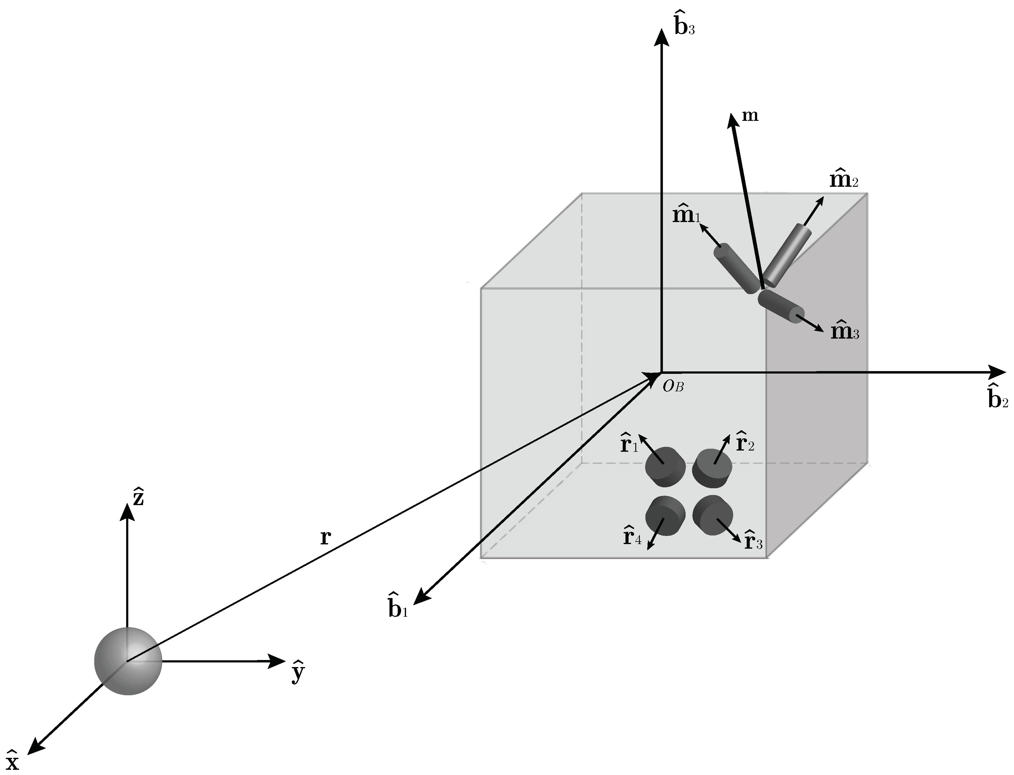
The problem of stored angular momentum management is inherently related to attitude control systems with momentum exchange actuators. In fact, momentum exchange actuators do not generate any external torque, but they exchange angular momentum with the main spacecraft body by means of internal torques, , which are generated by accelerating or decelerating a set of spinning rotors. This study considers a spacecraft with mass equipped with four reaction wheels, which are identified as with . These are organized in a redundant pyramid configuration and their spinning axes are denoted as . The torques generated by the reaction wheels are practically provided by the electric motors driving the rotors, which have their typical operational curve that is a function of the angular speed. Despite the specific typology of the electric motor, it is common to have a specific spin rate, where the practical torque level falls to zero, . This is called saturation speed, and, when the actuator reaches this speed, the motor cannot provide any additional torque in the direction of the increasing spin rate. Note that the four actuators are assumed to have the same saturation speed.
When the rotation rate of one actuator reaches the maximum value, , it has to be desaturated or unloaded from the stored angular momentum. In order to accomplish this task, an external torque is generated to maintain the spacecraft attitude control while the rotor is despun. In this case, three orthogonal magnetic torquers, which are identified as with , are placed inside the spacecraft and are aligned with the axes . They generate a magnetic dipole, , which interacts with the surrounding geomagnetic field, , producing a net torque on the spacecraft body: .
This study considers a spacecraft orbiting in LEO with various attitude modes. Inertial pointing, nadir pointing, target tracking, and velocity dumping modes are considered in this research study. The spacecraft attitude dynamics are described with Euler’s equation for rigid body motion, which is expressed in the body reference frame,
B, with origin in
. The spacecraft’s body axes are denoted as
,
, and
. The attitude of the spacecraft is referenced to an Earth-centered inertial (ECI) frame,
I, through the attitude matrix,
, which is parametrized in terms of the quaternion,
. The spacecraft orbital position is represented in
I by the radius vector
, which is associated to the inertial axes
,
and
. The complete problem setting is reported in
Figure 1.
Assuming the spacecraft has a constant inertia matrix,
, we can express the spacecraft attitude dynamics as:
where
is the spacecraft’s angular velocity expressed in the
B frame,
is the environmental disturbance torque,
is the previously mentioned magnetic control torque,
and
are the reaction wheels’ configuration matrix and vector of angular momenta, respectively. It is evident from Equation (
1) that the reaction wheels do not produce a net torque on the spacecraft, but they only exchange angular momentum with it. Indeed, the term
is the cumulative angular momentum of all the reaction wheels expressed in body frame, and the overall spacecraft’s angular momentum results in:
Formally, the configuration matrix
is a
matrix, whose columns represent the direction of the axis of rotation of each reaction wheel in
B:
and the vector of reaction wheels’ angular momenta
is a column vector with 4 elements representing the angular momentum of each rotor around its spin axis:
where
is the rotor’s inertia, which is equal for the 4 reaction wheels.
The quaternions, used to represent the spacecraft’s attitude, lead to the following representation for the attitude kinematics:
where
is the unit norm quaternion vector and the angular velocity matrix is expressed as:
The environmental disturbance torques taken into account to model the spacecraft dynamics are due to both external and internal effects. They are modeled according to the international standards for system simulation and verification [
26,
27]. In particular, gravity, magnetic, atmospheric drag, and radiation pressure torques are considered, as well as internal micro-vibrations-induced torques and electro–magnetic interaction disturbances.
2. Attitude Control System
The attitude control system is designed to control the spacecraft attitude while maintaining the stored angular momentum in the reaction wheels within pre-defined level boundaries. The combined control action of reaction wheels and magnetic torquers allows achieving this goal by continuously dumping the angular momentum stored in the actuators. Specifically, the magnetic control is designed to desaturate the reaction wheels, being integrated with a PID three-axis attitude control law. The latter is then actuated by the reaction wheels. The control design and tuning are particularly aimed at maintaining the two controllers’ bandwidths well separated, in order to avoid dangerous coupling between the two control loops, which could reduce the stability of the main three-axis attitude control.
The attitude control system is specifically intended to be applied on autonomous spacecraft and, for this reason, does not require any intervention from the ground in terms of attitude knowledge, guidance, or anomalies management. Ideally, the attitude determination should be performed on-board and should be robust with respect to faults and sensor anomalies [
28], the guidance functions should compute the reference attitude state on-board, and the system should be capable of detecting failures in the actuators and eventual anomalies in the angular momentum management functions. For instance, a threshold with respect to the practical actuator’s saturation speed should be defined in order to activate an emergency reaction wheels desaturation mode in the case the continuous angular momentum management fails. Note that this is the ideal application of the proposed attitude control system, but the architecture and the control laws described in this paper can also be applied to a generic spacecraft platform with lower autonomy and different features.
2.1. System Architecture
The attitude control system is intended to receive as input the estimated attitude quaternion from the determination block,
, and the reference attitude quaternion to be chased,
, computed by the guidance functions. The control action is then computed on the error quaternion, which is defined as [
29]:
Note that the proposed architecture does not need any assumption on the time evolution of the reference attitude state, and the present discussion is valid for both pointing and tracking attitude control. The implementation of PID attitude control also requires the definition of the error angular velocity as:
where the estimated angular velocity,
, is computed by the attitude determination functions or directly retrieved from a gyroscopic sensing unit; the reference angular velocity,
, is calculated in the attitude guidance block, and it shall be coherent with the desired time variation in the reference quaternion. Finally, to correctly manage the stored angular momentum, the system shall also receive as input the angular speed of each reaction wheel,
, and the best estimate of the surrounding geomagnetic field,
, expressed in the body frame. Thus, the system is equipped with rotary encoders on the reaction wheels and with magnetometers or alternative magnetic field estimation functions.
The integrated attitude control torque is a combination of two independent contributions:
where
and
are the three-axis attitude control PID torques actuated by the reaction wheels and by the magnetic torquers, respectively;
is the integrated desaturation torque commanded to the reaction wheels, which is defined to be compatible with the instantaneous magnetic controllability, as will be discussed in the dedicated section. The gain parameter
is used to tune the relative intensity of the two integrated control actions. This parameter is used to properly scale the torque levels sent to the reaction wheels and to the magnetic torquers to properly adjust them according to the torque performance of the actuators. Note that the proposed integrated attitude control system needs to have the combined action of both magnetic torquers and reaction wheels. Thus, the parameter
k must be different from 0 and 1. The best results in terms of balanced control subdivision between reaction wheels and magnetic torquers are obtained with a
k value in the order of
to
(i.e.,
to
) for typical spacecraft actuators. As a general tuning suggestion, the magnetic torquers should not generate torques greater than
of their maximum torque capacity during steady-state nominal operations, and they should reach torque saturation only at the maximum contingency. These design guidelines are derived from testing activities and analyses performed on different spacecraft systems. They should be used as preliminary suggestions to start the control design, which should then be customized on the specific system under consideration.
The control torques are finally converted in the actuation commands to be sent to the actuators. Thus, the desired torque is applied to each individual reaction wheel, and the magnetic dipole moment is generated by each magnetic torquer. The architecture of the proposed attitude control system is reported in
Figure 2.
2.2. PID Three-Axis Attitude Control
PID three-axis attitude control is a classical control law valid for both tracking and pointing modes [
30]. It is defined as:
where
and
are the vector and the scalar term of the error quaternion, respectively; and
,
, and
are the PID gain matrices. These are proportional to the spacecraft’s inertia matrix as:
They can be simplified assuming the body reference frame aligned or quasialigned with the principal inertia axes. In this case, they are diagonal matrices containing the principal moments of inertia. Note that the term is included in the control law to avoid the unwinding phenomenon, guaranteeing the shortest path to the final reference state.
The control design shall guarantee stability, which is inherently ensured by the control formulation via Lyapunov’s direct method [
3]. The control system design should guarantee robustness of the closed loop, and the tuning of the gains should achieve minimum stability margins. In particular, the phase margin shall be greater than 45 deg and the gain margin greater than 6 dB [
31]. However, the most important design goal for the proposed method is a minimum control bandwidth, which should guarantee a fast system response, well decoupled from the integrated angular momentum management control. Specifically, the three-axis attitude control should have a bandwidth 5 to 10 times larger than the other control loop. It has been seen that these values allow a good separation between the two control actions, without having a controller that is too demanding for common spacecraft hardware capabilities.
Thus, the previous design requirements impose minimum and maximum threshold values for the scalar PID gains
,
, and
. Specifically, the PID three-axis control system was designed considering:
where
is a single tuning parameter that should be selected according to the desired control bandwidth and to the available actuation capacity. Good results were obtained for
values in the range 1 × 10
−3 to 1 × 10
−2.
The computed PID control torque is then actuated both from the reaction wheels and from the magnetic actuators. The overall control torque level is preserved, but split between the two actuators according to the gain parameter
k, as described in Equation (
9) and represented in
Figure 2. This is to implement the integrated magnetic management of the stored angular momentum. In fact, at the same time the reaction wheels are commanded to actuate the PID controller, the final command sent to output is modified in order to maintain the stored angular momentum within predefined boundary levels. To compensate for this lack of actuation from the angular exchange actuators, the magnetic torquers are activated to achieve the same overall control. As discussed in the next section, this method is different from the classic ones where the magnetic actuators were only used to purely counteract the desaturation torque.
The actuation commands for the reaction wheels are computed considering the reaction wheels configuration and the spacecraft dynamics. Indeed, from the reaction wheels’ control torque,
it is possible to compute the actuation command for the reaction wheels,
, assuming that:
Knowing that the reaction wheels are commanded in terms of angular momentum variation as:
where
is the
vector containing the torque commands to be directly applied to each single rotor. The actuation commands for the three-axis PID attitude control become:
where
is the Mooree–Penrose generalized inverse of the configuration matrix
to distribute the torque among the 4 redundant reaction wheels with the the pseudo-inverse law [
29].
The actuation commands for the magnetic torquers are analogously computed from the PID control torque:
as:
In fact, because of the classical controllability issues with magnetic torquers, the control dipole calculation should take into account the surrounding magnetic field to maximize the available magnetic control torque
2.3. Integrated Magnetic Management of Stored Angular Momentum
The integrated magnetic management of stored angular momentum is practically realized combining magnetic torque with a momentum unloading command to the reaction wheels. The classical cross-product control law [
22] is directly applied to the magnetic torquers in order to balance the desaturation torque for the reaction wheels. However, if used in continuous mode during the nominal mission operations, the magnetic torque behaves as a perturbation for the dynamics, decreasing the stability of the overall attitude control system. With the proposed method, the magnetic torque is used to recover the PID three-axis attitude control action that is partially lost because of the integrated desaturation commands sent to the reaction wheels. Indeed, the angular momentum variation in the reaction wheels required by the PID control is corrected in order to manage the stored angular momentum. In this way, the reaction wheels’ unloading torque is calculated for the reaction wheels, and the magnetic control counteracts the desaturation torque by controlling the spacecraft to the desired attitude state.
In order to desaturate the momentum exchange actuators with a torque that can be practically balanced by the magnetic control action, the commands sent to the reaction wheels are calculated considering the surrounding geomagnetic field, as in the classical cross-product control law. Knowing on-board the angular momentum stored in the actuators owing to their encoders, the desaturation torque can be computed as:
where the gain parameter
is used to adjust the bandwidth of this control proportional to the stored angular momentum. Remembering that the integrated momentum management control should have a bandwidth 5 to 10 times smaller than the PID three-axis attitude control, this gain parameter was designed to be limited by an upper threshold as:
Moreover, should be tuned in a way that the desaturation torque is not higher that the maximum torque achievable by the magnetic torquers. Note that for this purpose, the desaturation torque can also be limited in the maximum absolute value to further avoid unloading the stored angular momentum at a rate that is not sustainable for the magnetic actuators.
The formulation of the desaturation control in Equation (
19) allows the generation of a desaturation torque that is orthogonal to the geomagnetic field, guaranteeing instantaneous controllability with the integrated magnetic control. The torque obtained is then commanded to the reaction wheels by distributing it according to the pseudo-inverse law as:
The overall command for the reaction wheels results from the integration of the PID and the desaturation control torques:
Desaturation control can be easily activated and deactivated in order to maintain the stored angular momentum within predefined level boundaries. In fact, the reaction wheels should not reach the saturation speed, but they should also be operated far from zero velocity, which is a condition commonly characterized by higher friction and larger vibrations of the rotor. For this reason, momentum unloading is switched off if the actuator’s spin rate is below a certain threshold. Similarly, an emergency dedicated desaturation mode is activated if the reaction wheel’s spin rate is above another threshold. Note that the low velocity threshold can stop the desaturation command for each individual wheel by zeroing only the single velocity component in the stored angular momentum calculation:
Analyzing the proposed method at the system level, the continuous integration of magnetic torque during the operative modes can interfere with some magnetic components on-board the spacecraft or with the magnetic cleanliness of the platform. If this is not allowed by system-level constraints, the proposed method should be actuated with different actuators. Specifically, the control torque should be commanded to nonmagnetic actuators (e.g., thrusters). Alternatively, if magnetic torquers are allowed, particular care should be taken with respect to the magnetometer’s measurements. Indeed, magnetic torquers generate a field that strongly disturbs the magnetic measurements. This issue needs to be avoided by properly alternating the usage of magnetometers and magnetic actuators. In such a way, the magnetometer’s measurements are not acquired at the same time of the magnetic control commands. Generally, the time gap between magnetic measurements and control should be at least three times the characteristic period of the magnetic actuators to allow the attenuation of the generated magnetic dipole.
3. System Performance
The proposed integrated magnetic control method for the management of the stored angular momentum was developed for applications in operative space software and hardware. Then, the verification of the control performancewas carried out with numerical model-in-the-loop simulations, exploiting a functional engineering simulator (FES) developed for satellite applications in Earth orbits. At first, after the preliminary analyses of the linearized system dynamics, the final tuning of the control system was performed on an ideal spacecraft model, without the inclusion of system disturbances (e.g., attitude determination errors and actuator inaccuracies). Various reference attitude states were considered: inertial pointing, nadir pointing, and target tracking modes.
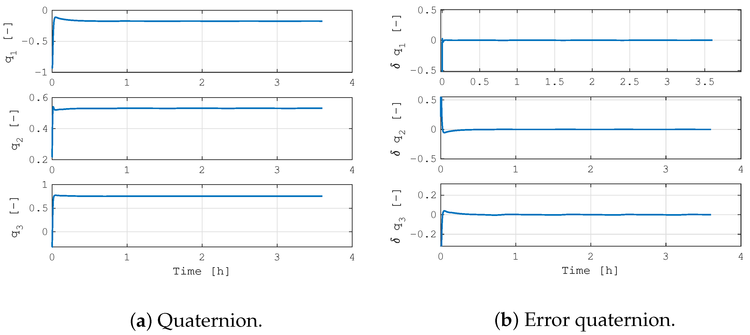
Figure 3 shows the results in the case of a system aligned with a reference inertial direction, where the plots report the quaternion and the error quaternion evolution over time. Note that only the quaternion vector part is shown, being the scalar part immediately available from the unit norm constraint. In this simulation, the system quickly converges to the reference state, and it reaches the complete steady-state condition in less than 15 min. However, the most important result is reported in
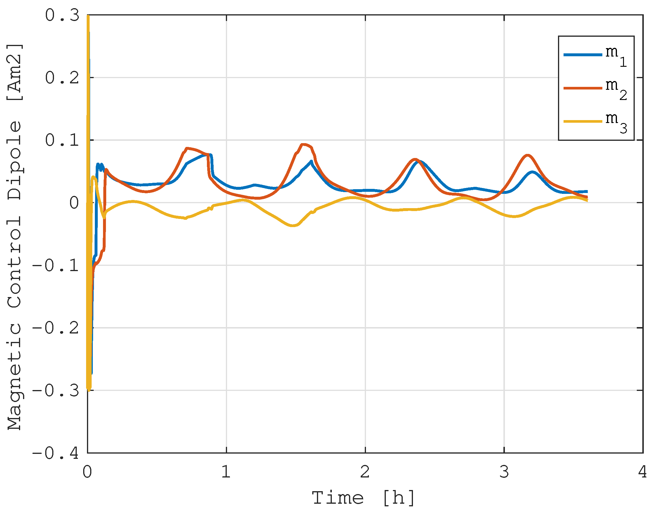
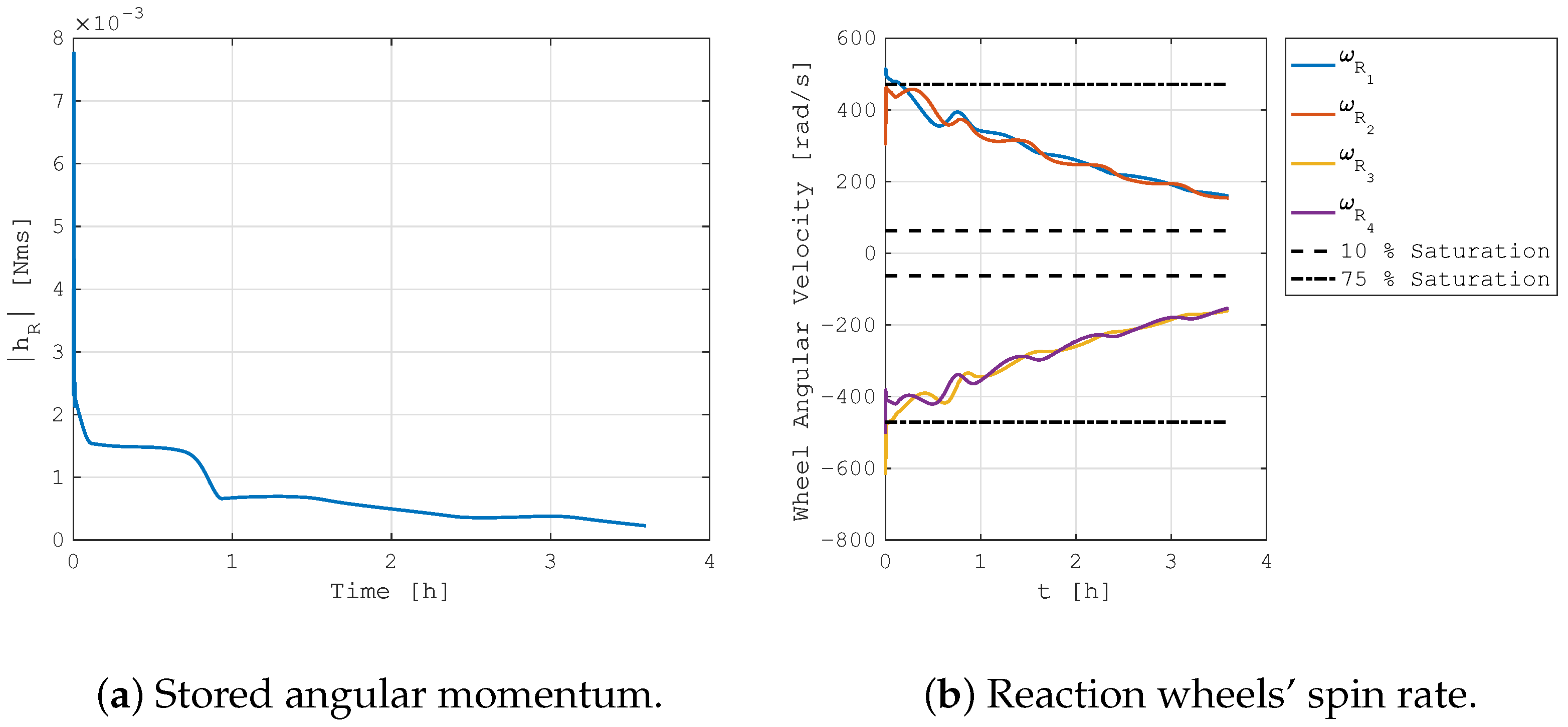
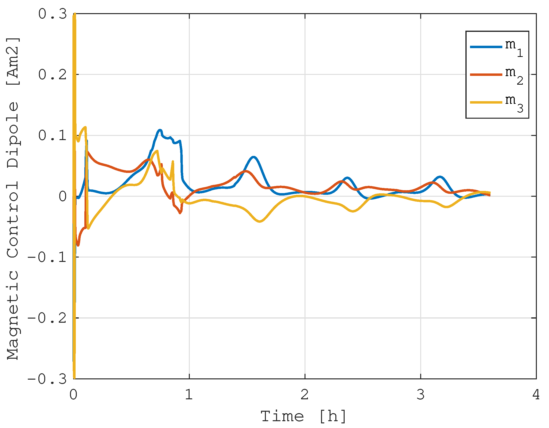
Figure 4, where the stored angular momentum is plotted with respect to time. For a more immediate visualization, the figure also reports the reaction wheels’ angular velocity. The angular momentum initially increases because of the required attitude maneuver to point in the reference direction, but it is quickly dumped out by the integrated magnetic momentum management control. In about 3 h, the reaction wheels are slowed to almost 10% of their maximum momentum capacity. Note that the simulation was initialized with the 4 reaction wheels at around 75% of the maximum storable angular momentum. This is achieved due to the integrated magnetic control law, which is commanded at the same time as the reaction wheels. The required magnetic dipole is reported in
Figure 5, showing that a continuous magnetic torque is actuated. In the presented analysis, the maximum available magnetic dipole is 0.3 Am
2, and the maximum momentum capacity of each reaction wheel is 2 × 10
−2 Nms. It can be highlighted how the continuous angular momentum management loads the magnetic torquers in the order of 30% of their maximum capabilities. Moreover, it is worth noticing how the pointing performance is not affected by the integrated control law.
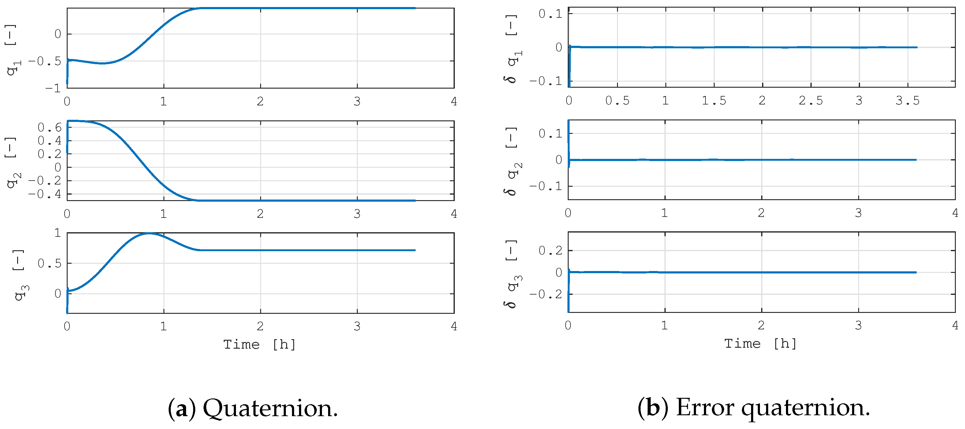
Similar results were also obtained in the tracking mode of a time-varying reference attitude. In this case, a generic slew maneuver is commanded to follow a predefined attitude profile. The system follows the time-varying reference for the initial 1.5 h; then, it maintains the final steady-state condition.
Figure 6 reports the time evolution of the attitude in terms of quaternions, together with the error with respect to the reference target state. Additionally, in this case, the attitude performance is demonstrated by a quick convergence to the desired state, followed by a good maintenance of the time-varying attitude profile. The integrated magnetic management of the stored angular momentum is capable of dissipating the reaction wheels’ spin rates, as shown in
Figure 7, without affecting the attitude control performance. Note that the oscillation in the reaction wheels’ speed, similar to the previous case, is due to the periodic trend in the external environmental perturbations. The magnetic torquers’ load is again about 30% of the maximum actuator capacity, as evident from
Figure 8.
Model-in-the-Loop Verification
After the preliminary results on the ideal case, the presented system performance was also validated with realistic simulations exploiting the FES models. In this context, the assumed scenario was well defined to better describe the actual performance of the proposed method.
Table 1 summarizes the main simulation parameters. The spacecraft considered in the verification campaign has moments of inertia in the order of 1 × 10
−1 kgm
2, and the actuators are analogous to those in the previous simulations. The system is orbiting in LEO on a Sun-synchronous orbit (SSO) with an altitude of 550 km and local time of ascending node (LTAN) at 06:00 a.m. The system was simulated considering an attitude determination performance model with an average determination error of 3 deg. The actuator’s functional models consider all the internal dynamics and errors, and they are representative of real spacecraft hardware. The reference attitude state was in nadir-pointing mode. The MIL results were analyzed and discussed in terms of pointing performance and stored angular momentum, which is the primary objective of the proposed control system. The initial conditions were randomly dispersed to better generalize the results, which were also verified in a similar simulation scenario and with alternative initial states. Finally, to facilitate the reader comprehension, it is stated that the integrated magnetic angular momentum management control has a bandwidth in the order of 5 Hz, while the three-axis attitude control is around 50 Hz.
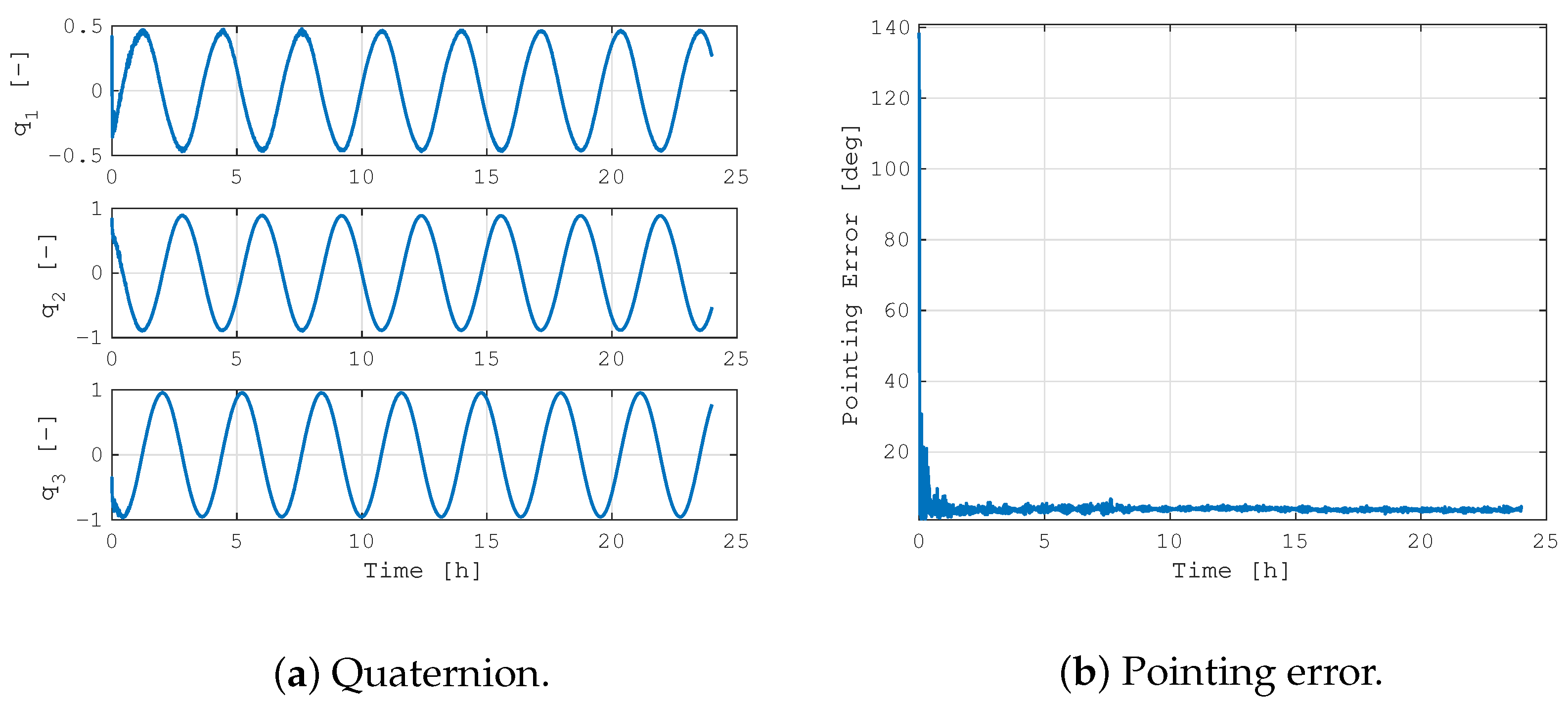
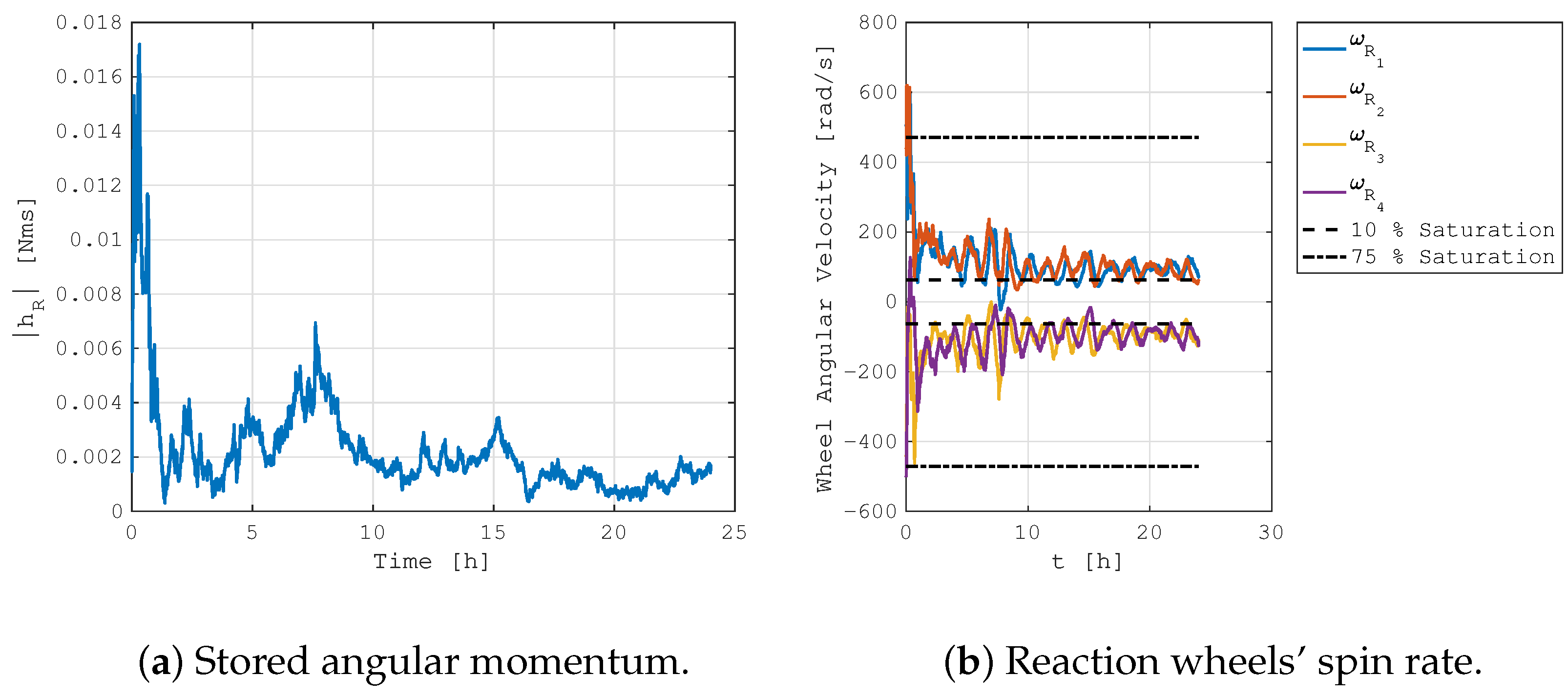
Figure 9 shows the dynamics’ evolution of the spacecraft in the considered mission scenario along a 24 h simulation. The periodic trend in the quaternion components is due to the nadir-pointing mode, and the pointing error value confirms the positive achievement of the proposed control system. Indeed, the residual error is mainly due to the attitude determination errors, while the small oscillation is associated with the reaction wheels’ jitter. The management of the angular momentum is effective even in the real case, with the average storage level in the low range of the plot, as shown in
Figure 10. The initial build-up of the momentum is positively dumped out in less than 30 min, and the average reaction wheels’ spin rate is about 10% of the saturation value. This is due to the fact that below this threshold, the integrated magnetic control is not active in maintaining the actuators far from the zero-velocity level, with a beneficial effect on the reaction wheels disturbances. Indeed, a minimum spin rate of the rotors minimizes the friction in the bearings and the vibrations due to the zero-crossing dead band. To further prove the positive impact of the proposed integrated control system, the same simulation was repeated with the continuous reaction wheels’ desaturation switched off.
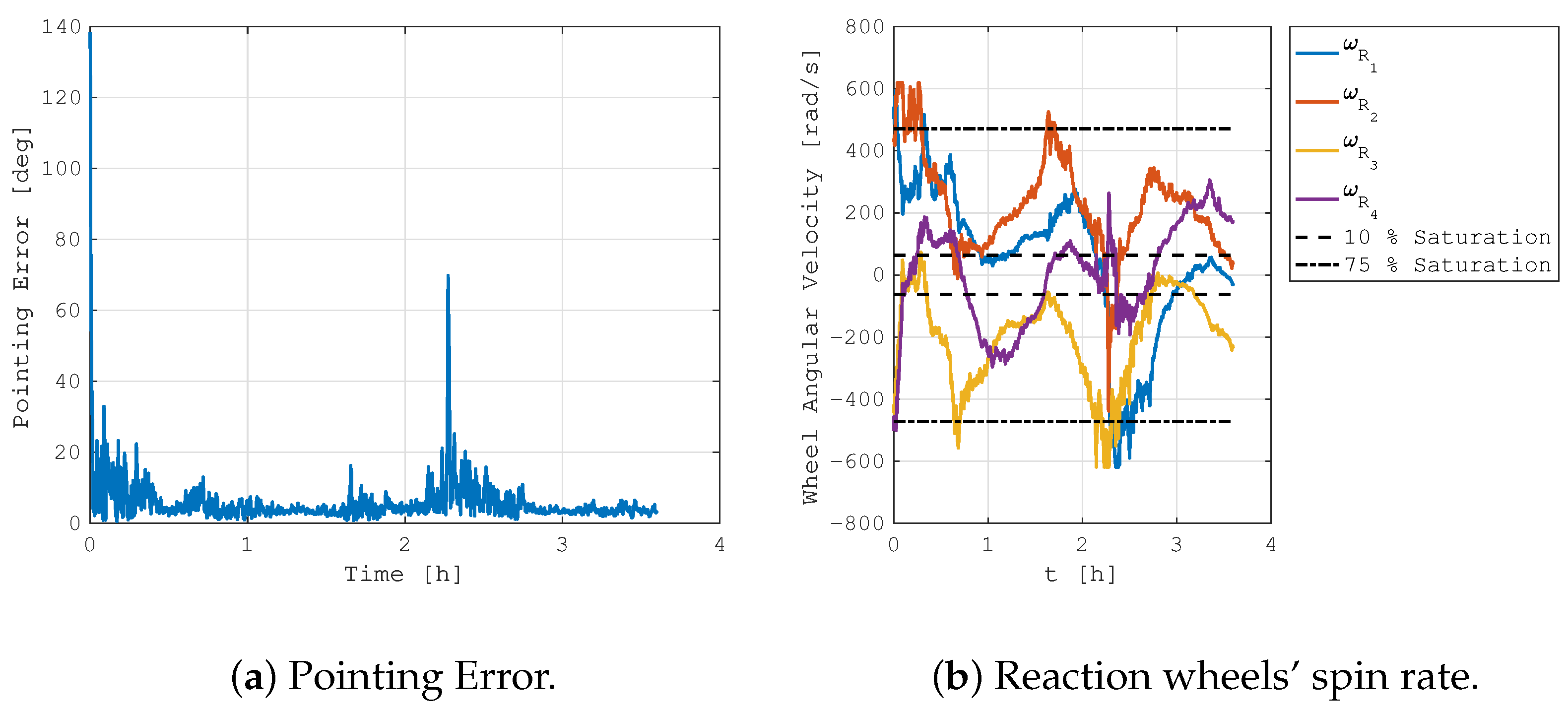
Figure 11 reports the pointing error and the reaction wheels’ spin rate for the same simulation scenario described above, but with pure three-axis PID attitude control. The simulation was run for 3.5 h, and it was initialized with the same initial conditions as the previous case. It is evident how the control performance is worse. Indeed, the higher average rotation rates of the rotors induce larger oscillations in the pointing error because of the higher jitter due to the static and dynamic imbalance of the actuators. Moreover, at
t∼2.5 h, the pointing error rises because of the saturation of two reaction wheels, namely,
and
. In this case, the real spacecraft system would have entered an emergency desaturation mode to avoid this problem. Furthermore, the system level performance would be affected by this trend because higher spin rates of the reaction wheels are typically associated with larger power consumption, which has a negative impact on the spacecraft’s power budget.
4. Velocity Dumping Control
The integrated control for the magnetic management of stored angular momentum can not only be applied to continuously desaturate the reaction wheels during three-axis attitude control modes, but can be easily modified to perform a fast and robust spacecraft’s velocity dumping, which can be exploited, for example, during the detumbling mode in the launch and early operations phase (LEOP) of a typical space mission. Despite the effectiveness and the simplicity of the well-consolidated "b-dot" control law [
10], there are situations in which the spacecraft’s velocity dumping is too slow. In these cases, the detumbling phase can be sped up with the use of reaction wheels. However, dumping the spacecraft’s velocity with momentum exchange actuators results in a fast build-up of the stored angular momentum, which soon leads to the actuator’s saturation. The integration of a simple velocity dumping controller with the proposed method for the magnetic management of the stored angular momentum allows solving this problem.
For this application, the main control law is a simple velocity proportional control:
where the gain parameter
is used to tune the rapidity of the controller in dumpingout the angular velocity of the spacecraft. Note that this parameter should be also tuned according to the maximum actuation capacity of the available actuators. The velocity dumping control is then split between the reaction wheels and magnetic torquers as in Equation (
9), and it is integrated with the desaturation torque as:
where the desaturation torque
is computed as explained in Equation (
19). Note that in this application, the velocity dumping and the desaturation controls should have approximately the same bandwidth to avoid a quickly stored angular momentum accumulation. Empirically, this is achieved by designing the gain parameter as:
Exploiting the same simulation approach described in the previous section and considering a similar case study scenario, the results of the proposed velocity dumping method are reported in
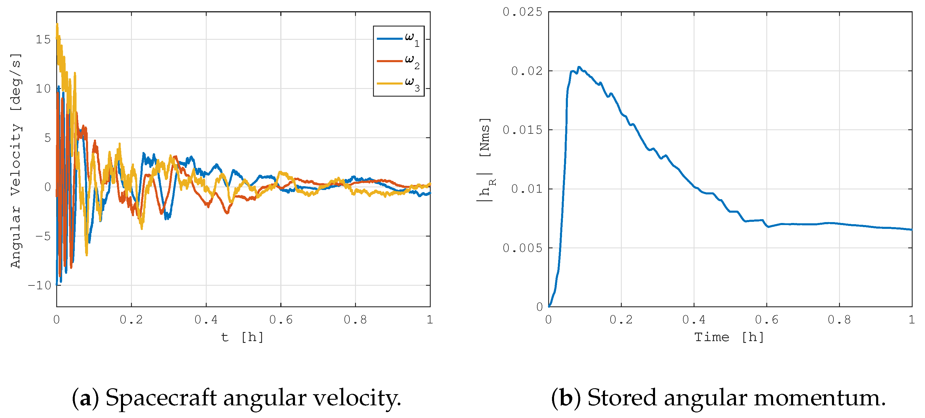
Figure 12, with the spacecraft initial tumbling rates in the order of 10
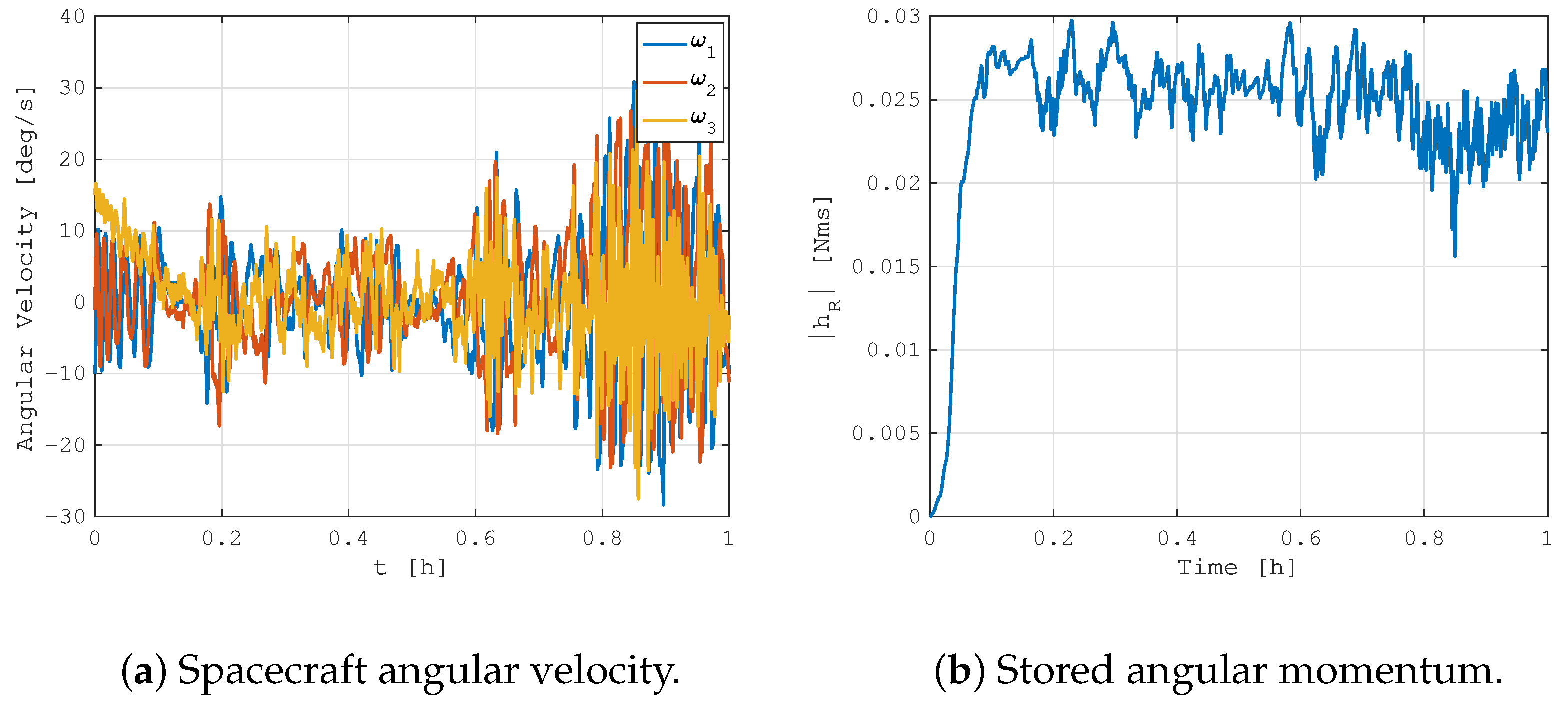
1 deg/s. It can be clearly seen how the proposed method is capable of dumping out the initial spacecraft angular velocity by accumulating it in the reaction wheels. At the same time, the application of integrated magnetic angular momentum management avoids reaching the saturation levels and quickly dissipates the stored angular momentum. The detumbling phase can be considered completed in less than 30 min, which is a good value compared with typical magnetic "b-dot" control performance. This did not happen in the simulation with the integrated control left inactive, shown in
Figure 13. As expected from classical control methods, the velocity dumping with angular exchange actuators is not effective and fails as soon as the reaction wheels reach the angular momentum saturation. In this case, the spacecraft begins to chaotically rotate, exchanging angular momentum with the internal rotors.
5. Final Remarks
The angular momentum stored in a spacecraft with momentum exchange actuators is of primary importance for attitude dynamics and control. The proper management of this physical quantity allows the effective mastering of the attitude stability, maintaining the actuators fully operative, and limiting their power consumption. Classical spacecraft systems manage the stored angular momentum with dedicated momentum dumping modes. This has a negative impact on the time available to carry out the primary mission operations and on the autonomy level of the spacecraft. Indeed, these dedicated desaturation modes need to be scheduled from the ground, or they are automatically triggered on-board with an interruption of the nominal routine. For these reasons, this study proposed the integrated magnetic control of the continuous and autonomous management of the stored internal angular momentum. Magnetic torques are coupled with classical PID three-axis attitude control commanded to the reaction wheels, whose actuation commands are modified at run-time to manage their angular momentum. The method modifies the classical approach to deal with this problem by proposing different settings of the available control laws. The control performance is improved, which was verified with numerical simulations. Specifically, model-in-the-loop (MIL) verification with a realistic functional engineering simulator (FES) was carried out to confirm the validity of the proposed approach. The method was also applied to realize an integrated velocity dumping controller, which can be used to quickly dissipate the initial tumbling rates of a spacecraft after its orbital injection. Even in this case, the results confirmed the effectiveness of the presented method, which can be exploited to speed up the detumbling phase with respect to other classical control laws. In general, the synergy between magnetic torquers and reaction wheels can be beneficially used on-board to improve system level performance, at the cost of a slight increase in the complexity of the platform and its operations.
