Article

Design and Structure Optimization of Arresting Gear Based on Magnetorheological Damper

1
State Key Laboratory of Mechanics and Control for Aerospace Structures, Nanjing 210016, China
2
Key Laboratory of Fundamental Science for National Defense−Advanced Design Technology of Flight Vehicle, Nanjing 210016, China
3
AVIC Jincheng Nanjing Engineering Institute of Aircraft System, Nanjing 211106, China
*
Author to whom correspondence should be addressed.
Aerospace 2023, 10(12), 1019; https://doi.org/10.3390/aerospace10121019
Submission received: 12 October 2023 / Revised: 9 November 2023 / Accepted: 6 December 2023 / Published: 8 December 2023

Abstract

:
The UAV cluster combat puts forward higher requirements for short-distance arresting gears for multitype aircraft. Based on magnetorheological technology, an arresting gear was designed, and the structural parameters of the MR damper were optimized. An iterative optimization method of structural parameters via a genetic algorithm combined with parametric modeling and magnetic field simulation was proposed. The optimization method was applied to optimize the structure of both a single-coil and double-coil damper. The performance of the optimized arresting gear was studied. The results show that, under the same zero field damping upper limit, the variation range of the damping force of the double coil increases by 10.2% compared with that of the single coil. Comparing the peak overload of UAV before and after the optimization, when the UAV mass increases from 4000 kg to 10,000 kg, the reduction in the peak acceleration is increased from 19.8% to 25.4%. Compared with traditional hydraulic arresting gear, the new arresting gear has good adaptability to UAVs with various qualities and has higher arresting efficiency. This arresting gear has a certain advanced nature.

1. Introduction

The network, information, services fused and reactive speed have become the key to the victory in the form of future war. A cooperative operation based on UAVs satisfies the requirements of future war [1]. UAV cooperative operations always come with the decentration and functional decentralization of UAV [2]. For that reason, the mass of medium and large UAVs varies [3], thus creating high requirements for the arresting force variation range and control ability of the arresting gear of UAV carrier platforms.
There are a few hydraulic arresting systems designed for medium and large UAVs. Huang [4] designed and studied a hydraulic arresting system for small UAVs by using dynamic simulation. This system cannot satisfy the requirement of medium and large UAVs’ arresting processes. Moreover, the hydraulic arresting system contains a necessary subsystem which consists of the arresting control valve and weight elector unit [5]. It controls the initial arresting force and the force during the arresting process. Because of the mechanical structure of the constant runout valve, the range of force variation is limited, and the resetting interval is long, which is the reason why it cannot be used to arrest the UAVs with short take−off and landing cycle intervals and a variety of masses. Making MR dampers replace traditional hydraulic dampers as damping force generation devices will significantly expand the range of damping force variation and increase response speed of force variation.
A magnetorheological damper is an intelligent damping force generating device that uses MR fluid to change its own rheological properties under different magnetic fields. The piston is an important component of the damper. The structural parameters and coil arrangement of the piston have a great influence on the performance of the damper. Hu [6] studied the shape of the piston and found that the damper with the flat−end piston configuration can obtain a greater damping force and a wider adjustable range of damping force. Khan [7] studied the effects of the piston chamfer; chamfer shape; and single coil, double coil, and triple coil on the damper’s performance. The study showed that the rounded piston chamfer could increase the pressure drop of the piston. Yazid [8] used the finite element method (FEM) magnetics software package to establish a magnetic field simulation model. Six parameters were proposed to obtain the best damper performance, and alternate polarities of coil also helped to strengthen the magnetic field in the shear and squeeze area. Current research provides guidance for the selection of parameters and coil arrangement.
Jang [9] optimized the minimum number of coil-turns and maximum adjustable range of a single-coil MR damper based on the genetic algorithm. Dong [10] took the damping force, adjustable range, response time and magnetic flux density as optimization objectives and optimized the geometric size of the magnetorheological damper for a bridge by utilizing the genetic algorithm. The optimization method of Dong’s study was to establish a numerical model. Then, it used the genetic algorithm to optimize the numerical model and used the finite element simulation to verify the optimization results. The processes of finite element magnetic field calculation and optimization are independent. Olivier [11] designed and analyzed an MR damper with two permanent magnets apart from an electromagnet. The optimization process was developed to optimize the geometric parameters and generated the maximum damping force of the hybrid MR damper by using the response surface method and Box-Behnken design. The genetic algorithm has potential parallelism for multiparameter optimization and has strong convergence. It is suitable for multiparameter optimization. The accuracy of the multiparameter optimization process can be improved if the FEM calculation is incorporated into it.
Magnetorheological dampers are also used in arresting gears. Fu [12] applied the MR damper to pulley shock absorbers for shipboard aircraft arresting system. Then, the fuzzy control rules were designed, and the buffer control for the pulley buffer of shipboard aircraft was completed in the touchdown moment based on MR technology. The pull peak of the arresting cable was reduced. However, MR dampers were not a source of resistance to stop the UAVs. Cheng [13] verified the accuracy of the modified sigmoid model by comparing the experimental data and calculation results. Then, a basic model for the carrier-based aircraft arresting gear was built, and the force of UAV during arresting process was demonstrated. They did not involve the structural parameter determination and structural optimization of MR dampers, and they did not carry out the deeper study of the dynamic response of the multitype UAV arresting process.
In this paper, based on parametric modeling, the finite element simulation results are connected to the genetic algorithm optimization process to improve the accuracy of optimization results. The optimization results of the single-coil arrangement and double-coil arrangement are compared. Finally, the simulation results are substituted into the UAV arresting model to verify the arresting performance of the device based on the MR damper.

2. Structure and Numerical Modeling of MR Dampers

The shear valve [14] magnetorheological damper was selected as the optimization object. This kind of damper has a simple structure and good reliability. When the aircraft pulls the arresting cable to drive the piston rod to move, the pressure of the MR fluid on one side of the piston increases, forcing the MR fluid to flow through the flow path between the piston and the cylinder to the other side. The piston winding coil will form a magnetic field between the piston and the cylinder. MR fluid flow characteristics are influenced by the magnetic field strength. Therefore, adjusting the current in the piston coil can be a good way to adjust the damping force. As shown in Figure 1, the coil winding modes of the dampers are divided into single-coil [15] and double-coil [6] modes.

2.1. Parametric Modeling of MR Dampers

2.1.1. Parametric Modeling of Single-coil MR Damper

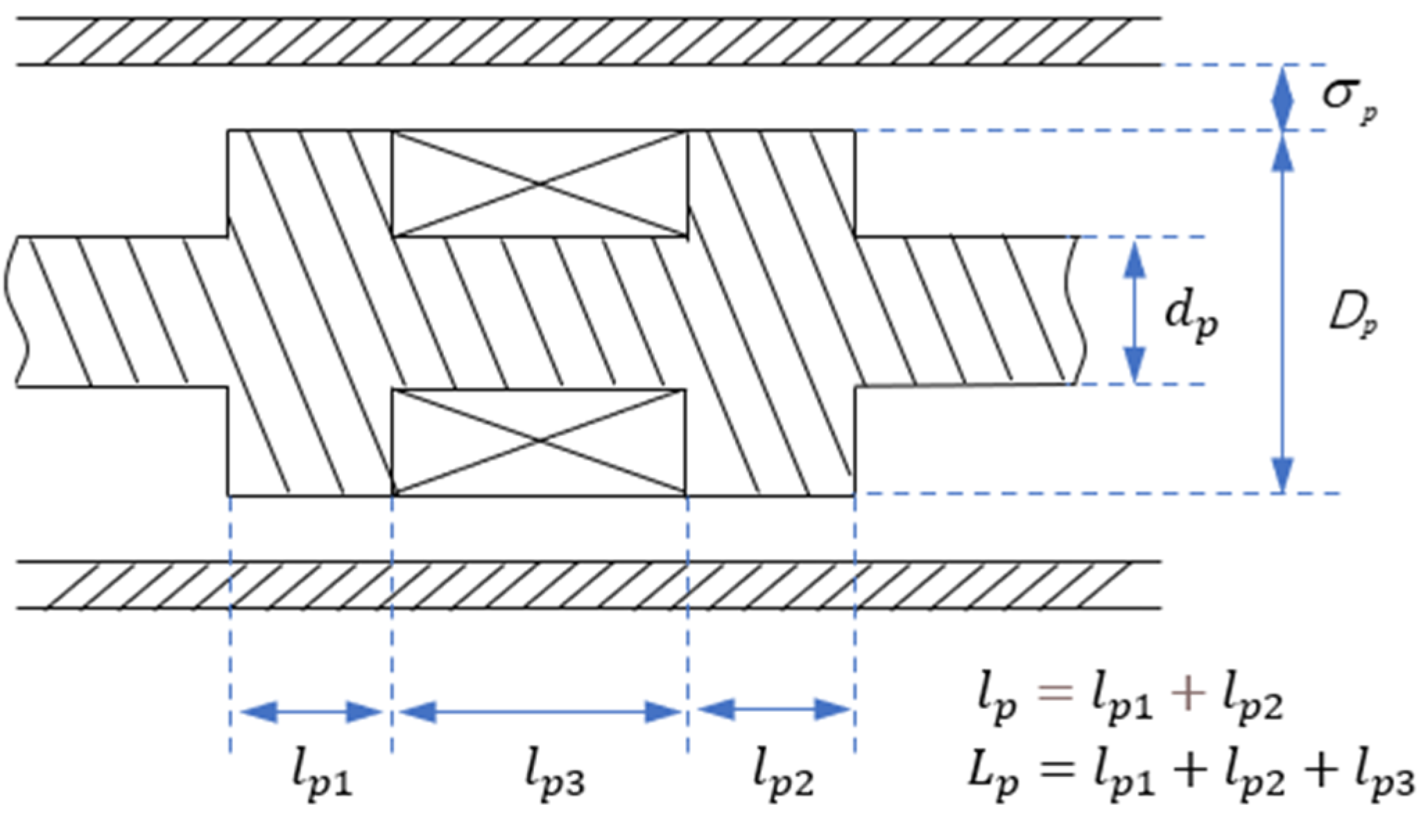
The structure of the single-coil shear valve magnetorheological damper is shown in Figure 2.
According to Figure 3, based on the Bingham constitutive relation, the force produced by the shear flow can be expressed as follows:
F s = π η D L σ p v p + π D L τ p y v p
According to Dong’s [16] simplified numerical model of the valve MR damper, the damping force of the valve MR damper can be expressed as follows:
F v = 12 η L A p 2 π d p σ p 3 v p + 3 L τ p y A p σ p v p
where Dp is the piston diameter, dp is the piston rod diameter, σp is the width of flow path, L is the piston length, vp is the velocity of piston, ηp is the apparent viscosity of MR fluid, and τpy is the shear yield strength of MR fluid.
For the damper in this paper, not only the piston is moving, but there is also a gap between the piston and the outer cylinder which causes the shear flow. Therefore, it can be viewed as a combination of the shear flow and valve flow.
F Z p = F v + F s
However, the Coulomb damping force (terms with τpy in Formulas (1) and (2)) does not act on the whole length of the flow path. It is not accurate to calculate the Coulomb damping force generated by the liquid shear with L. So, L is split into Lp and lp. The damping force and its composition are determined by the following formulas:
F Z p = F V p + F C p
F V p = 3 π η L p ( D p 2 d p 2 ) 2 4 D p σ p 3 + D p π η p L p σ p v p
F C p = 3 π l p ( D p 2 d p 2 ) 4 σ p + l p π D p τ p y
where FZp is the damping force, FVp is the viscous damping force, FCp is the Coulomb damping force, lp is the effective length of magnetic pole and Lp is the effective length of flow path.
The ampere turns’ calculation for the single-coil damper is shown below:
N p I p = Φ p ( R m 0 + R m 1 + R m 2 )
and then
N p I p = Φ p ( l p p μ 1 S p + 2 σ μ 2 S σ + l p c μ 3 S c )
where Φp is the total flux in magnetic path; Rm0 Rm1 Rm2 are the piston reluctance, the air gap reluctance and the outer cylinder reluctance, respectively; lpp lpc are the average length of the magnetic circuit of the piston and the outer cylinder, respectively; μ1 μ2 μ3 are the permeability of the piston, the MR fluid and the outer cylinder, respectively; and Sp Sσ Sc are the magnetic circuit cross-sectional area of the piston, the flow path and the outer cylinder, respectively.
The number of coil turns is limited by the structural parameters of the piston, and the current is limited by the coil and heat dissipation. Therefore, the total magnetic flux is chosen as the dependent variable, and its variation range affects the rheological properties of MR fluid. The total magnetic flux is determined by the following formula:
Φ p = N p I p R m 0 + R m 1 + R m 2

2.1.2. Parametric Modeling of Double-Coil MR Damper

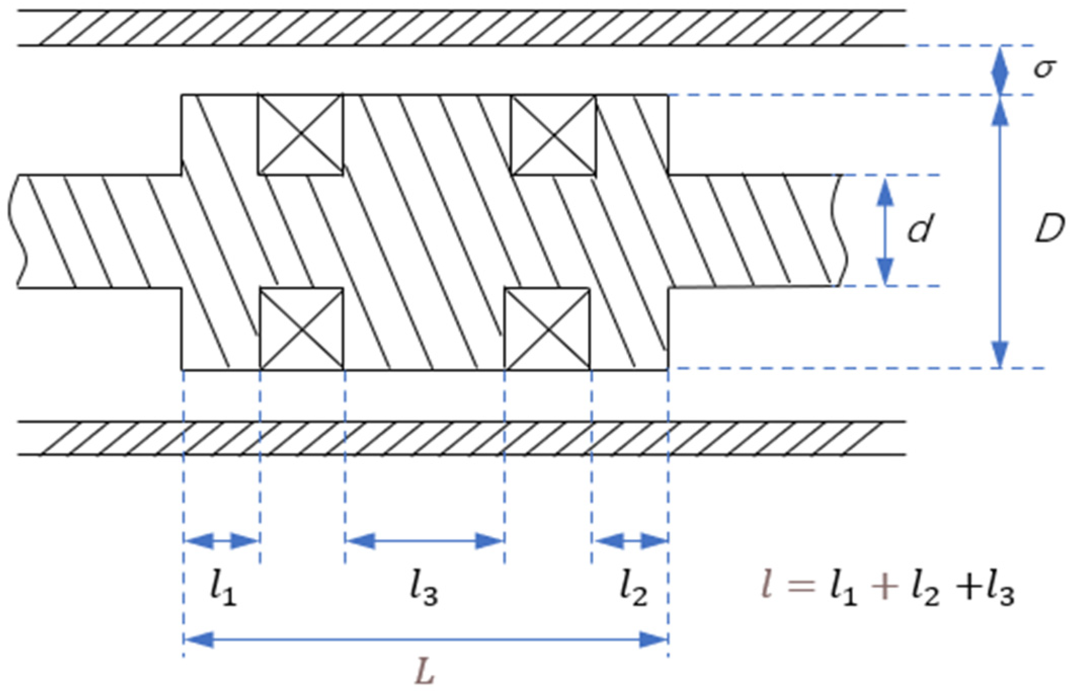
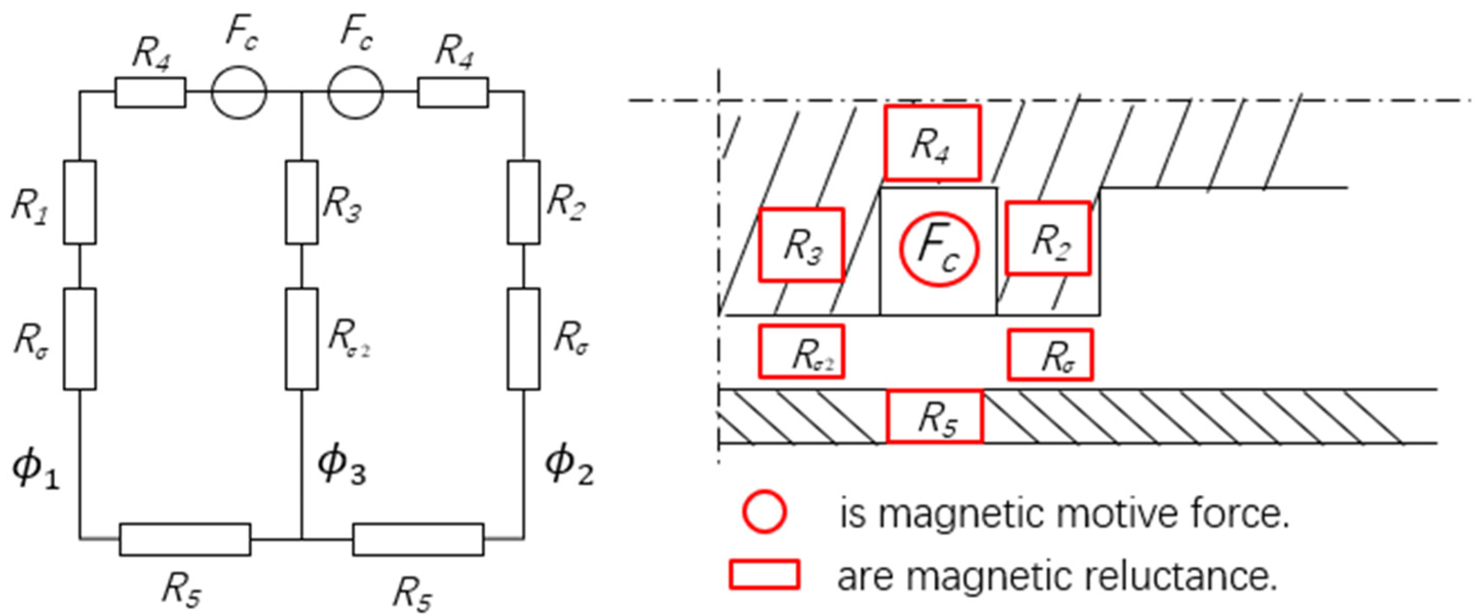
The structure parameters of the dual-coil shear valve magnetorheological damper are shown in Figure 3. According to the structure of the damper, the magnetoresistance analysis of the double-coil magnetic circuit is shown in Figure 4.
According to Figure 3, we need to establish Expressions (11)–(13) based on Expressions (5) and (6). The damping force numerical model of the double-coil MR damper is established as follows:
F Z = F V + F C 1 + F C 2
F V = 3 π η L ( D 2 d 2 ) 2 4 D σ 3 + D π η L σ v
F C 1 = 3 π ( l 1 + l 2 ) ( D 2 d 2 ) 4 σ + ( l 1 + l 2 ) π D τ y 1
F C 2 = 3 π l 3 ( D 2 d 2 ) 4 σ + l 3 π D τ y 3
where τy1 is the shear yield strength of MR fluids in flow path l1 and flow path l2 under the impact of magnetic field, and τy3 is the shear yield strength of MR fluid in flow path l3 under the impact of magnetic field.
A numerical model of the magnetic flux of double-coil is established based on Figure 4:
Φ 1 ( R 4 + R 1 + R σ + R 5 ) + ( Φ 3 Φ 2 ) ( R 3 + R σ ) = N 1 I 1
The coils are arranged symmetrically, so Φ1 = Φ2 = 0.5Φ3. Then, the following formula can be obtained:
Φ 1 = N 1 I 1 R 1 + R 3 + R 4 + R 5 + R σ + R σ 2
where R1~R4 are the piston reluctance; Rσ Rσ2 are the air gap reluctance; R5 is the outer cylinder reluctance; lpp lpc are the average length of the magnetic circuit of the piston and the outer cylinder, respectively; μ1 μ2 μ3 are the permeability of the piston, the MR fluid and the outer cylinder, respectively; and Sp Sσ Sc are the magnetic circuit cross-sectional area of the piston, the flow path and the outer cylinder, respectively.

3. Optimization Process

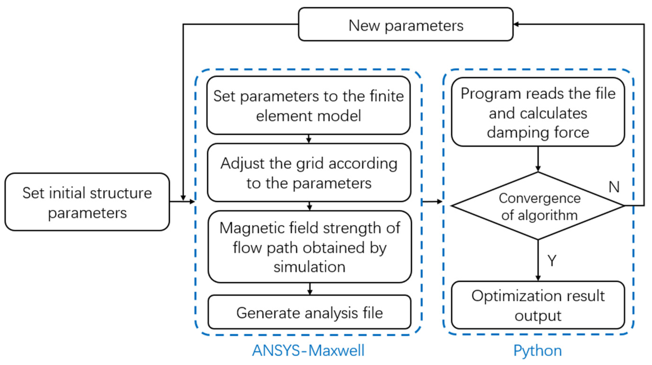
The optimization process is shown in Figure 5.
Python (Version 3.9.12) was used to establish a genetic algorithm multiparameter optimization model. Then, a parametric magnetic field simulation model was established based on ANSYS−Maxwell (Version 16.0). The initial structure parameters were passed from Python to Maxwell. Then, the finite element simulation model was rebuilt according to the parameters, and the grid of the finite element simulation model was also adjusted so that the model could provide higher calculation accuracy. The magnetic field strength of the flow path that was obtained via the simulation was stored in an analysis file and returned to Python. After reading the file, the program calculated the damping force. This set of structural parameters is selected and eliminated according to the boundary and optimization objective. By iterating over and over again, the optimal solution is obtained.

4. Introduction of Optimization Model

4.1. Determine the Structure Parameters to Be Optimized

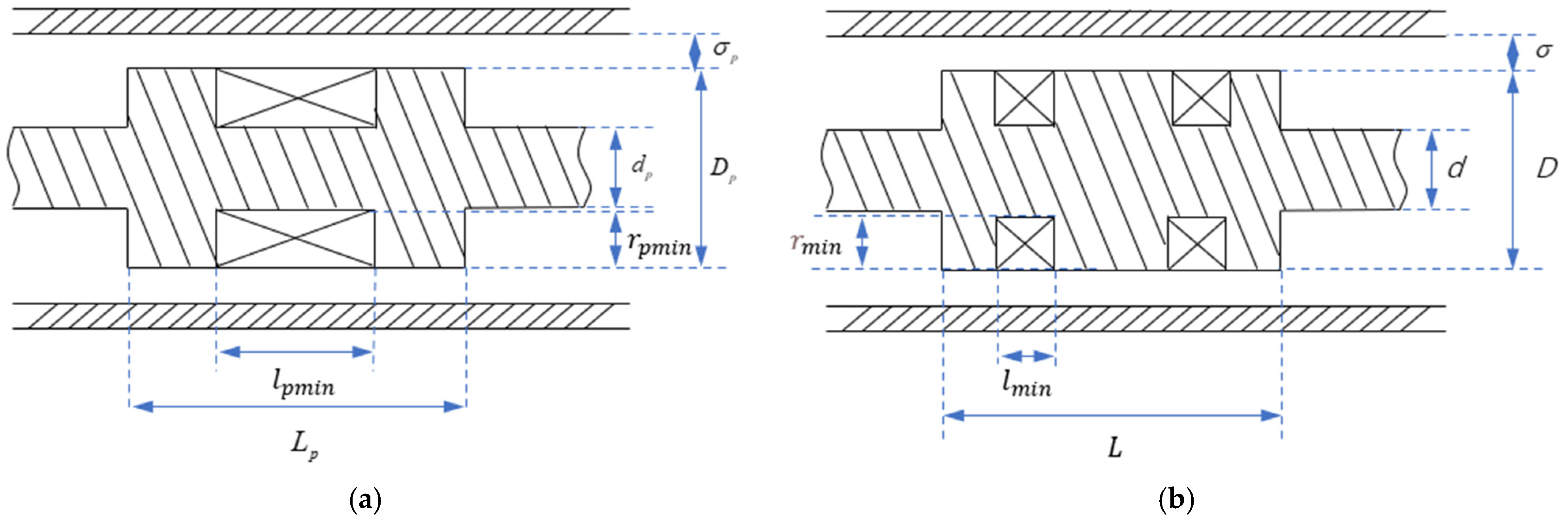
According to the numerical model of damping force established above, the main structural parameters that affect the damping force include the piston diameter, Dpmin(Dmin); piston rod diameter, dp(d); width of flow path, σp(σ); effective length of magnetic pole, lp(l); effective length of piston, Lp(L); and coil turns, Np(N). The number of coil turns is limited by its structural parameters. The depth of the coil embedded in the piston is rp min(rmin), and the length is lp min(lmin). The structural parameters to be optimized were obtained, as shown in Figure 6.

4.2. Finite Element Simulation Model of Magnetic Field of Damper

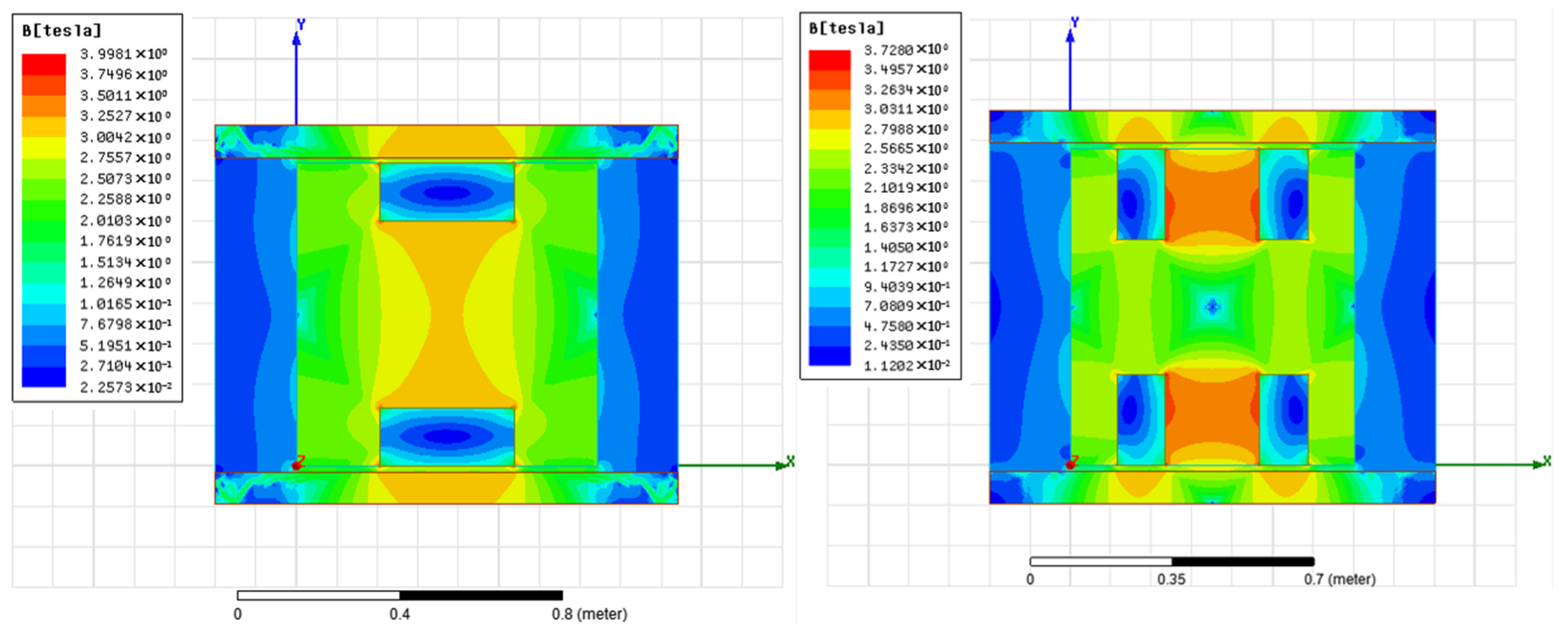
The parametric modeling of the MR damper was established by Ansoft−Maxwell, and Lord MRF241 was selected as the MR fluid. The magnetic field distribution was obtained by running the simulation. As shown in Figure 7, the magnetic field distribution is different between the single-coil and double-coil MR damper, and the magnetic field strength of the different magnetic poles is different in the double-coil MR damper. By reading the magnetic field strength at different locations of the flow path, the calculation accuracy of the damping force can be improved.

4.3. Boundary and Genetic Algorithm Optimization Model

Because the damping force is affected by the piston velocity, and the piston velocity is related to the UAV caught by the arresting cable, the piston speed is set to 1.8 m/s for the calculation of the UAV speed. The variation ranges of the structural parameters are shown in Table 1. We used the viscous damping force generated by the MR damper as the constraint boundary. The peak acceleration at the moment the UAV is caught by the arresting cable is minimized, and the upper limit of the zero−field damping force is defined as 2100 kN. The optimization objective is to maximize the Coulomb damping force variation range.
Because the diameter of the piston rod is affected by the velocity of the piston movement, we need to set the diameter to a quarter of the diameter of the piston. The total length of the coil must not exceed three−quarters of the length of the piston. The depth of the coil embedded in the piston must not exceed one−quarter of piston diameter. The effective length of the magnetic pole of the single-coil piston is lp = Lp − lp min, and the effective length of the magnetic pole of the double-coil piston is l2 = L2 − 2l2min.

4.4. UAV Arresting Dynamics Simulation Model

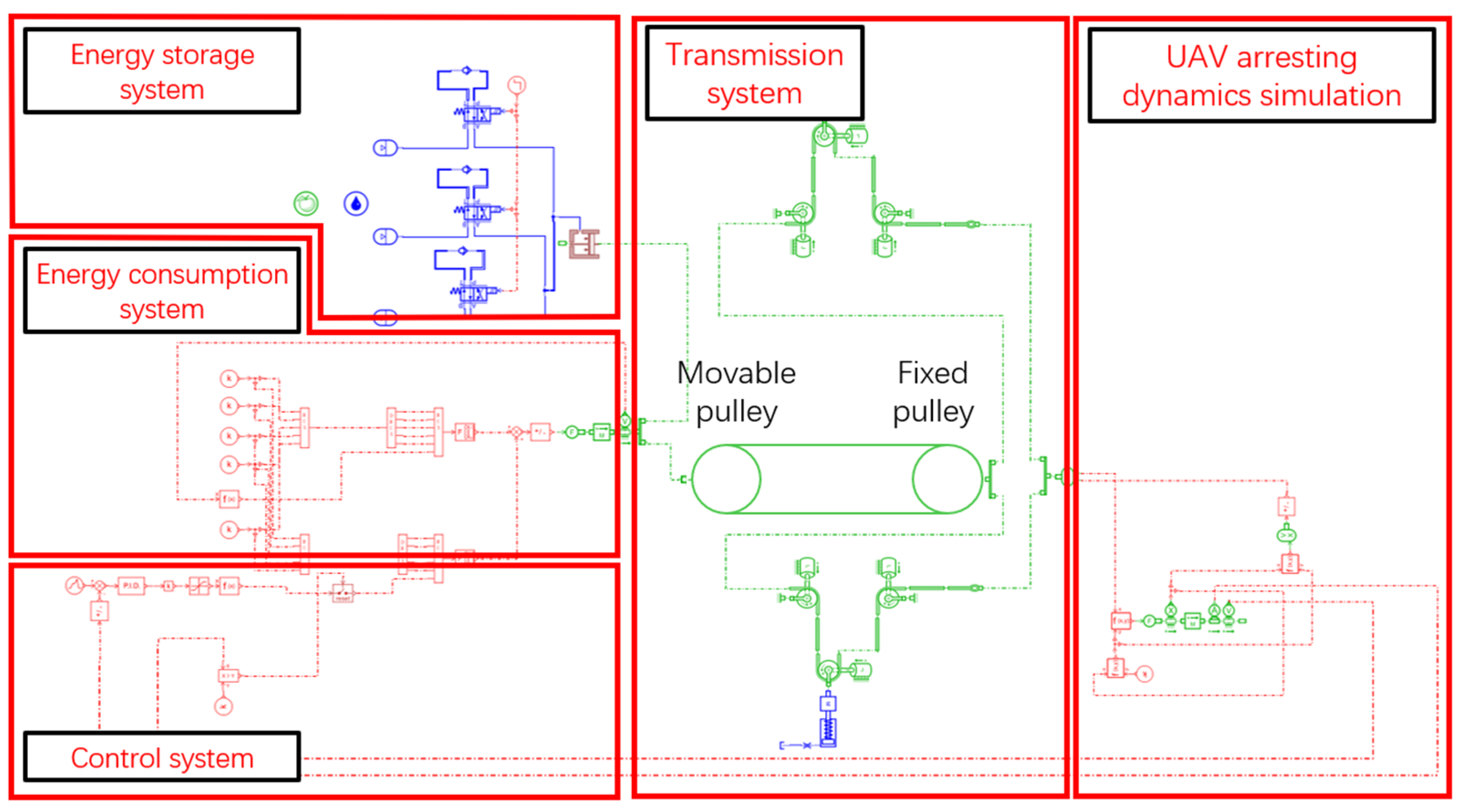
The UAV arresting gear base on the MR damper is shown in Figure 8. The UAV caught by arresting cable pulls out the cable. The force is transmitted to the MR damper and compressed air energy storge system by means of a transmission mechanism composed of pulleys. Part of the UAV’s kinetic energy is consumed by the MR damper, and part is stored for resetting the whole arresting gear. The control system will control the MR damper throughout the arresting process.
AMESim (Version 16.0) is used to build the simulation model based on Figure 8. By inputting the final optimization results into the AMESim simulation model, the UAV dynamic response is obtained and is then used to verify the optimization results and compare the influence of different coil arrangements on the damping performance of the MR damper.
The AMESim simulation model is shown in Figure 9. The MR damper is controlled by the active control system, and then the acceleration of the UAV can be adjusted immediately. The UAV arresting dynamics simulation module is used to simulate the process by which the UAV is caught by cable and stopped by the damping force through the cable. The transmission system simulates the force transmission process of the deck arresting cable to the energy consumption system. The energy consumption system is used to simulate the single/double-coil MR dampers.

5. Optimization Results and Analysis

We set the evolution group members to 10 and the evolution steps to 100. With the increase in the number of iterations, most parameters basically become stable after 600 iterations, while the coil depth became stable after 900 iterations. The final optimization results are shown in Table 2.
After optimization, the piston volume of the single-coil MR damper is 0.324 m3, and the double-coil piston volume is 0.333 m3. The double-coil piston volume is 28% larger than the single-coil piston volume. When the piston velocity is 1.8 m/s, the damping force variation range of the single-coil piston is 1,769,801 N, and that of the double-coil piston is 1,950,654 N, which is a 10.2% increase over the single-coil one.
The parameters of AMESim simulation model are set to the optimized parameters. The mass of the UAV is set as 4000 kg, 6000 kg, 8000 kg and 10,000 kg respectively. The initial speed of the UAV is 40 m/s, and the ideal acceleration of the control system is 20 m/s2. The adaptability of the MR damper and arresting system is verified by changing the mass of the UAV. The peaks of the UAV acceleration before and after structural optimization are shown in Table 3. The value of the parameters before optimization is the value that maximizes the damping force.
It can be seen that the structural optimization significantly reduces the peak accelerations of UAVs. For the single-coil damper, when the UAV mass increases from 4000 kg to 10,000 kg, the reduction in the peak acceleration is increased from 19.8% to 25.4%. For the double-coil damper, the reduction in peak acceleration is increased from 22.2% to 25.7%. The optimization of the damper structure not only reduces the peak load of the UAV during arresting but also expands the damping force variation range of the damper and improves the arresting efficiency of the damper.
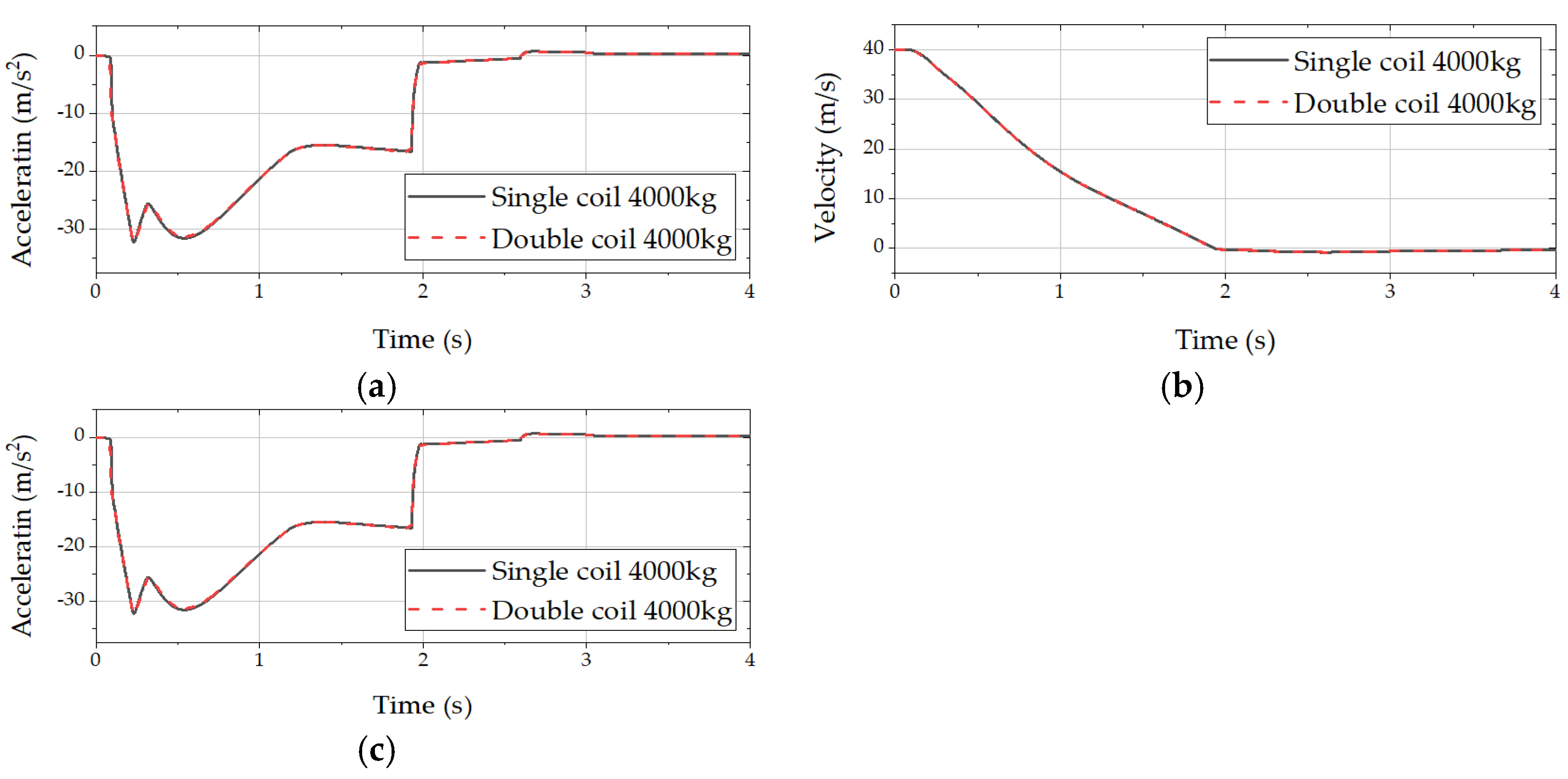
Furthermore, the effects of different coil arrangements on the performance of the MR damper are compared, and the simulation results are shown in Figure 10, Figure 11, Figure 12 and Figure 13.
As shown in Figure 10a and Figure 11a, the coil arrangement has no significant impact on the arresting process of small- and medium-mass UAVs. For a 4000 kg UAV, the acceleration of the UAV rapidly increases from 0 m/s2 to 32.5 m/s2 in the early stage of the arresting process, decreases to 15 m/s2 within 0.8 s and then maintains a slow rise until the UAV is stopped. For a 6000 kg UAV, the peak arresting acceleration decreases to 24.8 m/s2, and then it drops to 19 m/s2 and remains at this value until the UAV is stopped. As can be seen from Figure 10b and Figure 11b it takes 1.9 s for the arresting gear to stop the UAV of 4000 kg and 2.0 s for the UAV of 6000 kg. As shown in Figure 10c and Figure 11c, the arresting gear stops the 4000 kg UAV at 35.1 m, and the 6000 kg UAV needs 41.9 m to stop. Therefore, different coil arrangements have no significant impact.
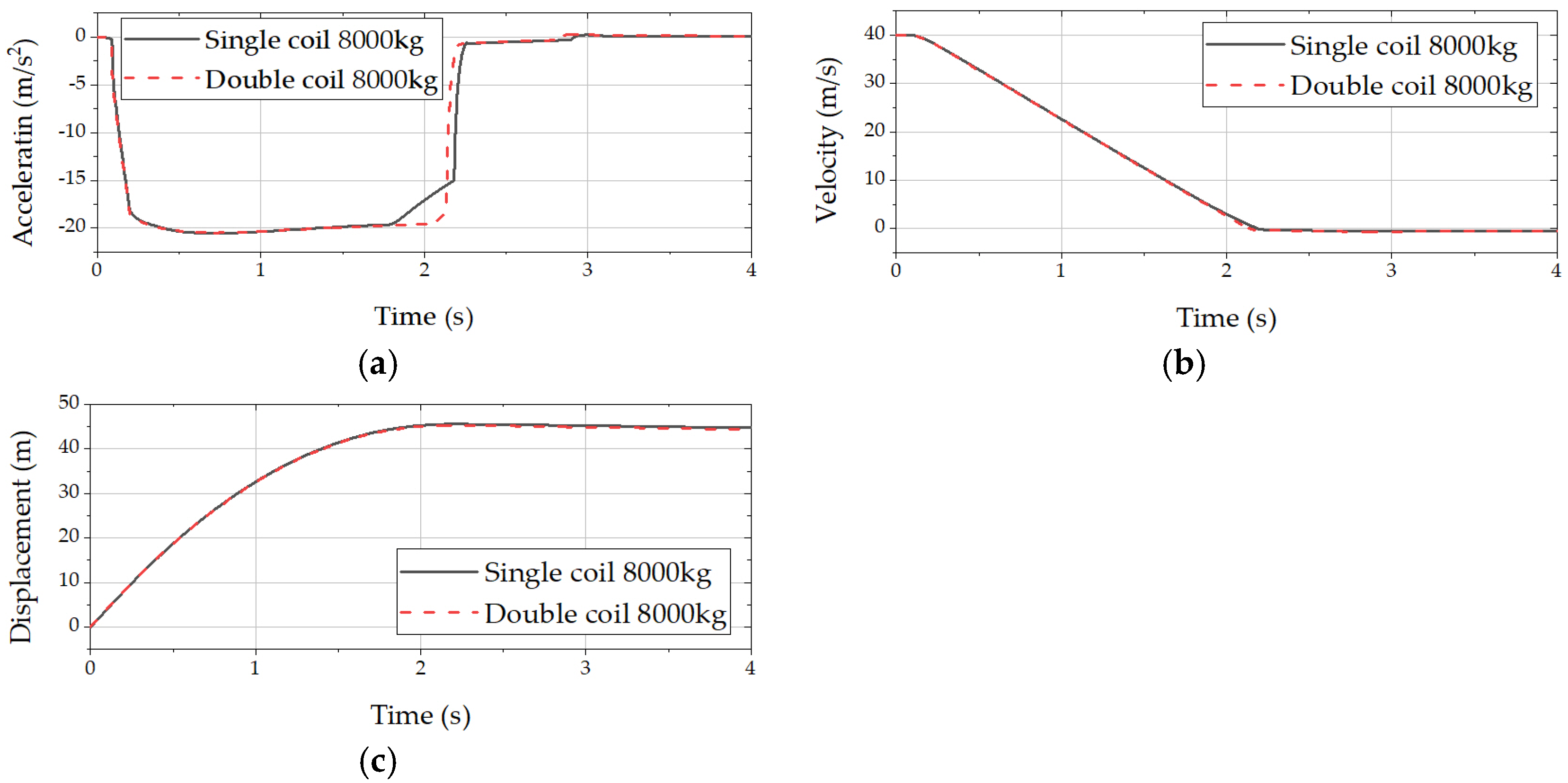
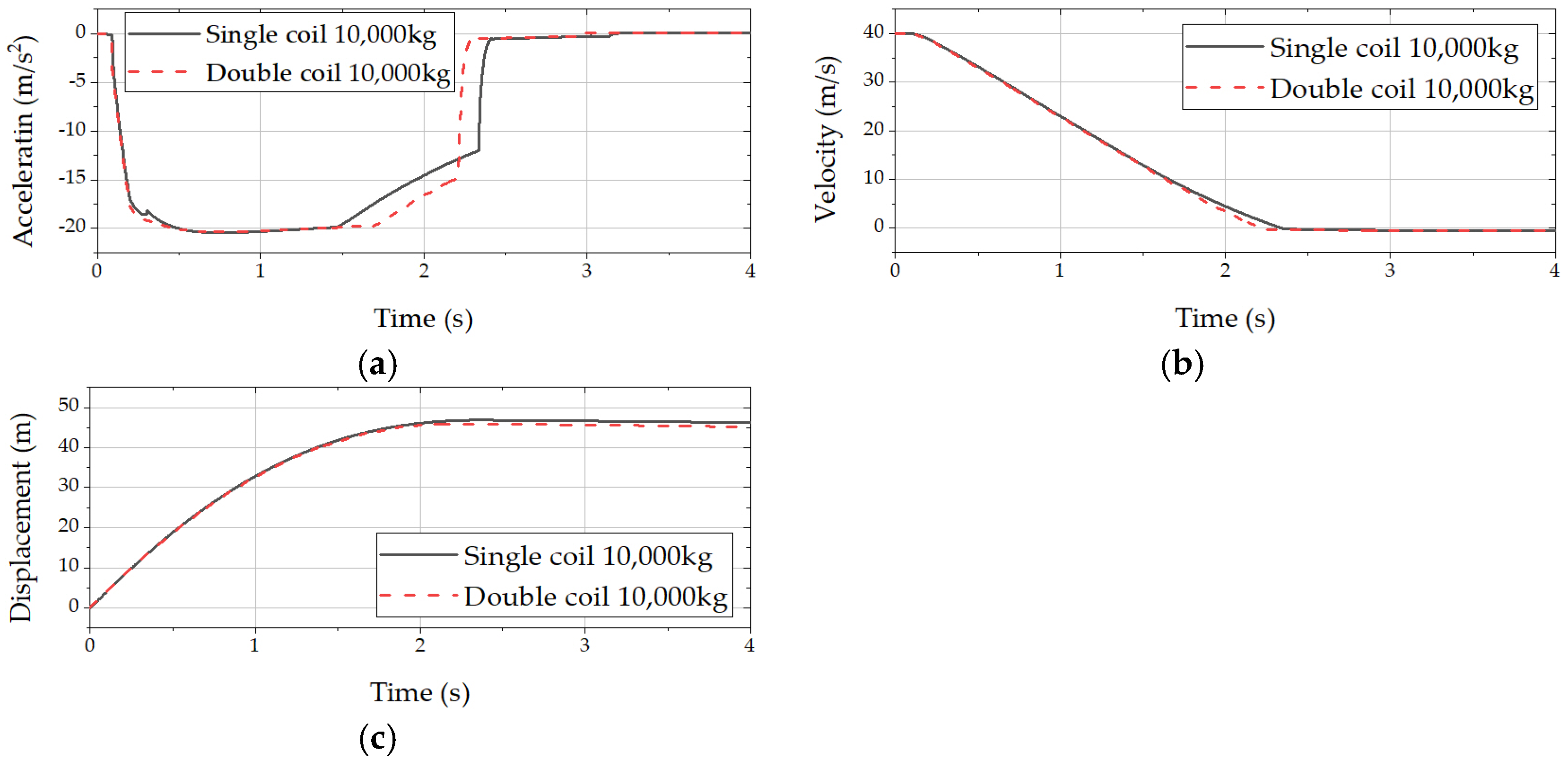
As shown in Figure 12 and Figure 13, the coil arrangement has a great influence on the arresting performance of the high−mass UAV. Under the condition of 8000 kg UAV, the arresting performance appears to have an obvious difference after 1.8 s, and the single-coil damper appears to have an obvious inflection point at 1.8 s. After 0.4 s, it decreases from 20 m/s2 to 15.0 m/s2. The double-coil damper has no obvious inflection point, and there is a small but not obvious decline after 2.1 s. The single-coil arresting gear takes 2.2 s to stop the UAV within 45.5 m. The double-coil arresting gear’s stopping time is 2.1 s, 4.5% lower than that of the single-coil one, and the arresting distance is 44.5 m, which is 2.2% shorter. When the UAV mass is 10,000 kg, the single-coil inflection point appears at 1.4 s, and the double-coil inflection point appears at 1.7 s, i.e., 21% delayed. It takes 2.4 s for the single-coil arresting gear to stop the UAV at 45.5 m. I confirm. The double-coil arresting gear takes 46.5 m to stop the UAV, so the distance is shortened by 2.2% compared with that of the single-coil arresting gear. The arresting time is 2.2 s, making it 9.1% shortened.
In summary, after optimization via the genetic algorithm, the arresting performance of the double-coil damper was better than that of the single-coil damper. Combined with Table 2, it can be seen that, under the conditions of a similar viscous damping force, the Coulomb damping force of the double-coil damper is greater than that of the single-coil damper. Under the condition of the same total coil length, the coil depth of the double-coil damper is shallower than that of the single-coil damper, indicating that the magnetic field generation efficiency of the double-coil damper is better than that of the single-coil one. From the UAV acceleration curve, it can be seen that the performance differences of the different coil arrangements of the dampers are mainly reflected in the arresting process of the large-mass UAV. Under the condition of the UAV with a high mass and low speed, the acceleration maintenance time of the double coil is longer than that of the single coil, the arresting efficiency is higher and the performance is better.
Because the hydraulic arresting gear designed for medium and large UAVs is rare, this paper refers to the force line of MK7-I, and the hydraulic arresting gear is reproduced. On this basis, the hydraulic arresting gear is adjusted so that the hydraulic arresting device can be adapted to the medium and large UAVs. Taking the force line of 10,000 kg UAV as an example, the comparison with MK7-I [17] is shown in Figure 14.
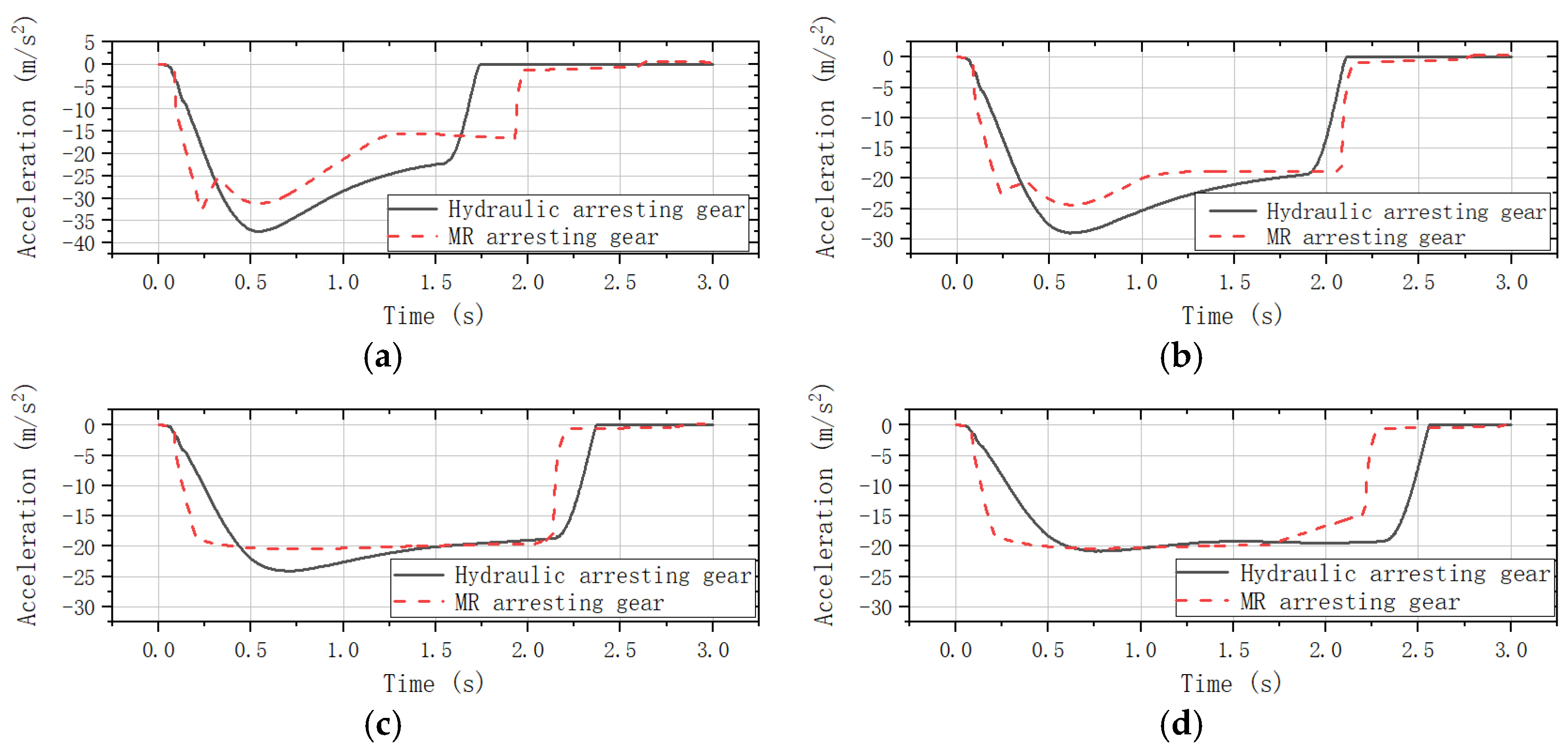
It can be seen from Figure 14 that the result of the hydraulic arresting gear simulation model is reliable. The acceleration simulation results according to the change in the mass of the UAV are shown in Figure 15.
According to the Figure 15, the MRAG (MR arresting gear) has a much faster response time than the HAG (hydraulic arresting gear). Since the best arresting performance of HAG is designed for 10,000 kg UAV, with the mass decreases from 10,000 kg to 4000 kg, the peak load of the UAV becomes higher. The damping force control performance of the runout valve becomes poorer and poorer when the UAV mass deviates from the design point. Moreover, the runout valve is a passive control unit, meaning that it cannot control the damping force according to the state of the arresting object during the arresting process like the MRAG can.
The arresting displacement difference between 4000 kg UAV and 10,000 kg UAV is 11.4 m for the MRAG and 18.3 m for the HAG, as seen in Table 4. It shows that the stopping points of the MRAG are more concentrated than those of the HAG. The same phenomenon also appears during the arresting time, meaning that there is better predictability and controllability. As for acceleration, the peak acceleration of the MRAG is 13.1% lower than that of HAG for 4000 kg UAV, 14.5% for 6000 kg UAV, 14.9% for 8000 kg UAV and 4.3% for 10,000 kg UAV.

6. Conclusions

In this paper, the structural parameter optimization model of the MR damper is established based on the genetic algorithm, and the structural parameters of dampers with different coil arrangements are optimized. The dynamics simulation model of the UAV arresting process is established, and the following conclusions are obtained:
(1) Maxwell and Python were used to establish the structural parameter optimization model of the MR damper based on the genetic algorithm and finite element magnetic field simulation. Under the same constraints, the structural parameter optimization results of the single-coil MR damper and the double-coil MR damper were calculated, respectively. It is found that, under the approximate volume and structure, the variation range of the damping force of the double-coil damper is increased by 10.2% compared with that of the single-coil damper; thus, performance of the single-coil damper is inferior to that of the double-coil damper.
(2) The model of the UAV arresting gear based on magnetorheological technology was established by AMESim. When the UAV mass increases from 4000 kg to 10,000 kg, the reduction in the peak acceleration is increased from 19.8% to 25.4%.
(3) By substituting the optimized parameters into the simulation model, based on the obtained UAV dynamic response, the adaptability of the arresting gear to a variety of mass UAVs was studied. Under the action of the control system, there is an obvious damping-force regulation process.
(4) Compared with the hydraulic arresting gear, the response of MR arresting gear is faster. The UAV’s stopping points are more concentrated. The peak acceleration of the UAV is reduced by between 4.3% and 14.9%. It illustrates the adaptability of the arresting gear based on the MR damper to multitype and multi-mass UAVs.

Author Contributions

Conceptualization, J.H. and Y.P.; methodology, J.H.; validation, J.H., Y.P., H.M. and X.W.; formal analysis, J.H.; investigation, J.H.; resources, J.H. and Y.W.; data curation, J.H.; writing—original draft preparation, J.H.; writing—review and editing, J.H., Y.W., Y.P., H.M and X.W.; visualization, J.H.; supervision, H.M., X.W. and Y.P.; project administration, Y.P. All authors have read and agreed to the published version of the manuscript.

Funding

This research was funded by the National Natural Science Foundation of China (52202441), Natural Science Foundation of Jiangsu Province (BK20220910), the Aeronautical Science Foundation of China (20200028052010), the Fundamental Research Funds for the Central Universities (NT2022002), and the National Defense Outstanding Youth Science Foundation (2018−JCJQ−ZQ−053).

Data Availability Statement

Data are contained within the article.

Conflicts of Interest

The authors declare no conflict of interest.

References

  1. Zhang, J.; Xing, J. Cooperative task assignment of multi−UAV system. Chin. J. Aeronaut. 2020, 33, 2825–2827. [Google Scholar] [CrossRef]
  2. Fan, J.; Li, D.; Li, R.; Wang, Y. Analysis on MAV/UAV cooperative combat based on complex network. Def. Technol. 2020, 16, 150–157. [Google Scholar] [CrossRef]
  3. Liu, L.; Liu, D.; Wang, X. Analysis of the development status and outlook of UAV clusters and anti−UAV clusters. Acta Aeronaut. Et Astronaut. Sin. 2022, 43, 4–20. (In Chinese) [Google Scholar]
  4. Huang, J. Research on launching and recycling technology of a small marine unmanned aerial vehicle. Nanjing Nanjing Univ. Aeronaut. Astronaut. 2019, 45–61. (In Chinese) [Google Scholar] [CrossRef]
  5. Mohan Raju, S.; Manjunath, H.G.; Narayan, N. Modeling of Aircraft Arresting Gear System by Multibody Dynamics Approach and Co−Simulation of Multibody Dynamics with Hydraulic System Using Adams and Easy5. In Advances in Engineering Design and Simulation: Select Proceedings of NIRC 2018; Springer: Singapore, 2020; pp. 249–262. [Google Scholar]
  6. Hu, G.; Liu, F.; Xie, Z. Design, analysis, and experimental evaluation of a double coil magnetorheological fluid damper. Shock Vib. 2016, 2016, 4184726. [Google Scholar] [CrossRef]
  7. Khan, M.S.A.; Suresh, A.; Ramaiah, N.S. Analysis of magnetorheological fluid damper with various piston profiles. Int. J. Eng. Adv. Technol. 2012, 2, 77–83. [Google Scholar]
  8. Yazid, I.M.; Mazlan, S.A.; Zamzuri, H. Parameters Consideration in Designing a Magnetorheological Damper. Key Eng. Mater. 2013, 543, 478–490. [Google Scholar] [CrossRef]
  9. Jiang, M.; Rui, X.; Yang, F. Multi−objective optimization design for a magnetorheological damper. J. Intell. Mater. Syst. Struct. 2022, 33, 33–45. [Google Scholar] [CrossRef]
  10. Dong, Z.; Feng, Z.; Chen, Y. Design and multi−objective optimization of magnetorheological damper considering the consistency of magnetic flux density. Shock Vib. 2020, 2020, 7050356. [Google Scholar]
  11. Olivier, M.; Sohn, J.W. Design and geometric parameter optimization of hybrid magnetorheological fluid damper. J. Mech. Sci. Technol. 2020, 34, 2953–2960. [Google Scholar] [CrossRef]
  12. Fu, L.; Wei, Y.; Zhou, Y. Modeling and control of the pulley buffer system of arresting cable for shipboard aircraft based on magneto−rheological fluid. J. Shanghai Jiaotong Univ. (Sci.) 2012, 17, 573–578. [Google Scholar] [CrossRef]
  13. Cheng, T. Study on Mechanical Modeling of Carrier−based Aircraft Arresting Cable on Magneto−rheological Damper. Shenyang Shenyang Aerosp. Univ. 2012, 2012, 26–44. (In Chinese) [Google Scholar]
  14. Khedkar, Y.M.; Bhat, S.; Adarsha, H. A review of magnetorheological fluid damper technology and its applications. Int. Rev. Mech. Eng. 2019, 13, 256–264. [Google Scholar] [CrossRef]
  15. Ganesha, A.; Patil, S.; Kumar, N.; Murthy, A. Magnetic field enhancement technique in the fluid flow gap of a single coil twin tube Magnetorheological damper using magnetic shields. J. Mech. Eng. Sci. 2020, 14, 6679–6689. [Google Scholar] [CrossRef]
  16. Dong, P.; Tang, J. Application of MR Smart materials in structural vibration control. Appl. MR Smart Mater. Struct. Vib. Control 2000, 2, 15–18. (In Chinese) [Google Scholar]
  17. MIL−STD−2066; Military Standard: Catapulting and Arresting Gear Forcing Functions for Aircraft Structural Design. Department of the Navy Air Systems Command: Patuxent, MD, USA, 1981; pp. 108–114.
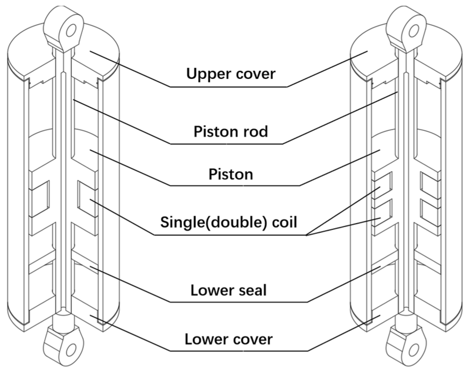
Figure 1. Single-coil MR damper and double-coil MR damper.
Aerospace 10 01019 g001
Figure 2. Structure parameter of single-coil MR damper.
Aerospace 10 01019 g002
Figure 3. Structural parameter of double-coil MR damper.
Aerospace 10 01019 g003
Figure 4. Magnetic circuit of double-coil MR damper.
Aerospace 10 01019 g004
Figure 5. Optimization flowchart.
Aerospace 10 01019 g005
Figure 6. Parameters that need to be optimized: (a) parameters to be optimized for single-coil damper and (b) parameters to be optimized for double-coil damper.
Aerospace 10 01019 g006
Figure 7. Difference of magnetic field distribution between single− and double-coil MR dampers.
Aerospace 10 01019 g007
Figure 8. Component of arresting gear.
Aerospace 10 01019 g008
Figure 9. AMESim arresting simulation model.
Aerospace 10 01019 g009
Figure 10. Arresting performance comparison of 4000 kg UAV: (a) UAV acceleration comparison, (b) UAV velocity comparison and (c) UAV displacement comparison.
Aerospace 10 01019 g010
Figure 11. Arresting performance comparison of 6000 kg UAV: (a) UAV acceleration comparison, (b) UAV velocity comparison and (c) UAV displacement comparison.
Aerospace 10 01019 g011
Figure 12. Arresting performance comparison of 8000 kg UAV: (a) UAV acceleration comparison, (b) UAV velocity comparison and (c) UAV displacement comparison.
Aerospace 10 01019 g012
Figure 13. Arresting performance comparison of 10,000 kg UAV: (a) UAV acceleration comparison, (b) UAV velocity comparison and (c) UAV displacement comparison.
Aerospace 10 01019 g013
Figure 14. Comparison between AMESim hydraulic simulation model and MK7-I.
Aerospace 10 01019 g014
Figure 15. Acceleration simulation results: (a) 4000 kg UAV acceleration comparison, (b) 6000 kg UAV velocity comparison, (c) 8000 kg UAV displacement comparison and (d) 10,000 kg UAV displacement comparison.
Aerospace 10 01019 g015
Table 1. Range of parameters variation.
ParameterSymbolLower LimitUpper LimitUnit
Piston diameterDp(D)0.71.0m
Depth of coil embedded in the pistonrpmin(rmin)0.100.20m
Width of flow pathσp(σ)0.0060.015m
Coil length of the single-coil damperlpmin0.200.40m
Coil length of the double-coil damperlmin0.100.20m
Piston−length−to−diameter ratioLp/Dp0.61.0
Table 2. Summary of optimized result.
ParameterSingle CoilDouble Coil
ValueUnitValueUnit
Piston radius0.389m0.376m
Coil depth0.244m0.198m
Width of flow path0.0149m0.0149m
Coil length0.200m0.100m
Ratio of piston length to diameter0.877 0.999
Strength of magnetic field1.757TMiddle 2.405T
Sides 1.3
Damping force3,869,462N4,050,563N
Viscous damping force2,099,661N2,099,909N
Table 3. Peaks of UAV acceleration before and after structural optimization.
UAV MassBefore OptimizationAfter Optimization
4000 kg (single-coil damper)−40.5m/s2−32.5m/s2
6000 kg (single-coil damper)−31.1m/s2−24.8m/s2
8000 kg (single-coil damper)−28.8m/s2−21.0m/s2
10,000 kg (single-coil damper)−26.8m/s2−20.0m/s2
4000 kg (double-coil damper)−41.8m/s2−32.5m/s2
6000 kg (double-coil damper)−32.6m/s2−24.8m/s2
8000 kg (double-coil damper)−29.2m/s2−20.5m/s2
10,000 kg (double-coil damper)−26.8m/s2−19.9m/s2
Table 4. Comparison between MR arresting gear and hydraulic arresting gear.
UAV MassDisplacementArresting TimeAcceleration
MRHydraulicMRHydraulicMRHydraulic
4000 kg35.1 m31.8 m1.9 s1.7 s−32.5 m/s2−37.4 m/s2
6000 kg41.9 m39.5 m2.0 s2.1 s−24.8 m/s2−29.0 m/s2
8000 kg44.5 m45.4 m2.1 s2.4 s−20.5 m/s2−24.1 m/s2
10,000 kg46.5 m50.1 m2.2 s2.6 s−19.9 m/s2−20.8 m/s2
Disclaimer/Publisher’s Note: The statements, opinions and data contained in all publications are solely those of the individual author(s) and contributor(s) and not of MDPI and/or the editor(s). MDPI and/or the editor(s) disclaim responsibility for any injury to people or property resulting from any ideas, methods, instructions or products referred to in the content.