Robust Flight Control Design to Minimize Aircraft Loss-of-Control Incidents

Abstract
:1. Introduction
“Finding 1-1 Adverse (PIO) events are fundamentally interactive and occur during highly demanding tasks when environmental, pilot, or aircraft dynamic changes create or trigger mismatches between actual and expected aircraft responses (emphasis added).”“Recommendation 4-3 Organizations should adopt and implement minimization techniques in design and development policies, processes, and procedures. These techniques should be tailored and routinely updated to accommodate applications of newly developed technologies (emphasis added).”

2. Vehicle Model
3. Frequency Domain Sliding Model Control System Design
3.1. The Design Procedure
- (1)
- A vehicle model is obtained. If the vehicle in question is nonlinear, a linearized version is obtained for initiating the SMC design. Actuator dynamics are ignored at this stage. The linearization here is only evoked to allow classical frequency-domain design techniques to be employed in the synthesis procedure to be described.
- (2)
- A square control structure is identified. The design requires that no transmission zeros lie in the right-half plane and any uncontrollable states must be asymptotically stable. These requirements are similar to those employed in feedback linearization designs. Observability of the linear model must be in evidence to accommodate the observer design to be discussed in Step (7). The control loop structure in the square system is based upon a simple premise. Consider a square structure containing “m” control loops eventually driving a single control variable uc. Define the inner-most loop as loop “1”, with the next being “m − 1”, etc. The transfer function of the linearized vehicle model for the control loop “1” should have a relative order of unity. The command variable in the “m − n” loop is, over a limited but important frequency range, the approximate integral of the command variable in the “m − (n + 1)” loop. Sequential loop closure design like that just described is certainly not novel, e.g., [18]. Its use here, however, forms the basis of the step-by-step design procedure being described.
- (3)
- Sliding mode control is limited to the inner-most control loops in the structure. The control law for each of these loops is given byand the sliding manifolds σ for each control channel are selected.
![Aerospace 01 00001 i002]()
- a)
- σ for any channel is derived from a tracking error expression such aswhere ξ is the relative order of the system. Here e(t)ξ-i refers the (ξ-i)th derivative of e(t). An integral term also appears in Equation (2) to counter the steady-state bias often created with the inclusion of a boundary layer.
![Aerospace 01 00001 i003]()
- b)
- Recognizing that a boundary layer is to be implemented, the control law is expressed as a linear transfer function,The parameters Ki are chosen to provide “desirable” properties in the frequency domain. This means creating a loop transmission with broad K/s-like characteristics around crossover. The minimum Kρ is that which permits pure gain or PI compensation in the frequency range at and beyond which ξ = 1, while exhibiting adequate gain and phase margins.
![Aerospace 01 00001 i004]()
- (4)
- With the K( - ) values just determined, the existence of sliding behavior is verified through computer simulation. A convenient and practical choice for ρ is the amplitude limit of the actuator for the loop in question. Thus uc(t) is the output of a relay element with limits of ±ρ.
- (5)
- A boundary layer is included in the controller to eliminate the high-frequency switching in the control variable(s) uc(t).
- (6)
- Actuator dynamics are now included in the computer simulation. Instability will typically result. This condition highlights the effect of so-called “parasitic dynamics” in the SMC design procedure.
- (7)
- Asymptotic observers are created for each channel with actuator dynamics still eliminated in the observer design. The eigenvalues of the observers are selected as real and (approximately) equal, and are determined by either maximizing the stability margins evident in “effective” unity feedback loop transmissions Leq, e.g., [13], or simply by selecting the eigenvalues near the bandwidth of the actuators.
- (8)
- To increase robustness, “hedge” dynamics can be created in which an additional loop is closed in parallel with the observer. Briefly, the hedge dynamics further decrease the destabilizing effects of the actuator in the loop in question. The method for choosing hedge dynamics can be found in [10] and will be summarized here. Hedge dynamics are created from a Bode diagram of the hedge dynamics transfer function Ghedge as follows: The magnitude plot of the hedge dynamics should exhibit (a) a +20 dB/dec slope at low frequencies, (b) a −20ξ dB/dec slope at frequencies near the actuator bandwidth, where ξ is the relative order of the vehicle dynamics in the loop in question (excluding actuators), and (c) a (−20ξ – 20) dB/dec slope at high frequencies. The gain value is chosen so that the magnitude of the Bode diagram of the hedge dynamics equals that of the transfer function of the appropriate observer output to SMC output near the natural frequency of the appropriate actuator [10].
- (9)
- In some applications, the addition of a rate-feedback loop in the inner-most control loops to which FDSMC is being applied can be considered. This was done, for example in [19]. Here “rate” refers to the fact that the derivative of the output of the inner-most feedback loop is utilized. In this case, it would be pitch and roll acceleration.
- (10)
- If desired, the observer(s) of Step (7) can be scheduled with flight condition.


3.2. Design Specifics for the GTM Vehicle
- (1)
- The vehicle model in the Appendix was mechanized in Simulink® and linearized about a flight condition of steady-wings-level flight at a trim velocity of 110 ft/s. This step required an estimation of trim values of pitch attitude, θ0, angle of attack, α0, thrust level, T0, and elevator angle, δe0. These were estimated as: θ0 = 5/57.3 rad, α0 = 5/57.3 rad, T0 = 5 lbf, δe0 = 0 rad. The results of [15] provided guidance in choosing these values. It should be emphasized that after the SMC design is complete, the initial trim value can be obtained exactly, as the final SMC controller will “self-trim” in simulation. For reference, the following pitch and roll-rate open-loop transfer functions were obtained at this stage:
![Aerospace 01 00001 i005]()
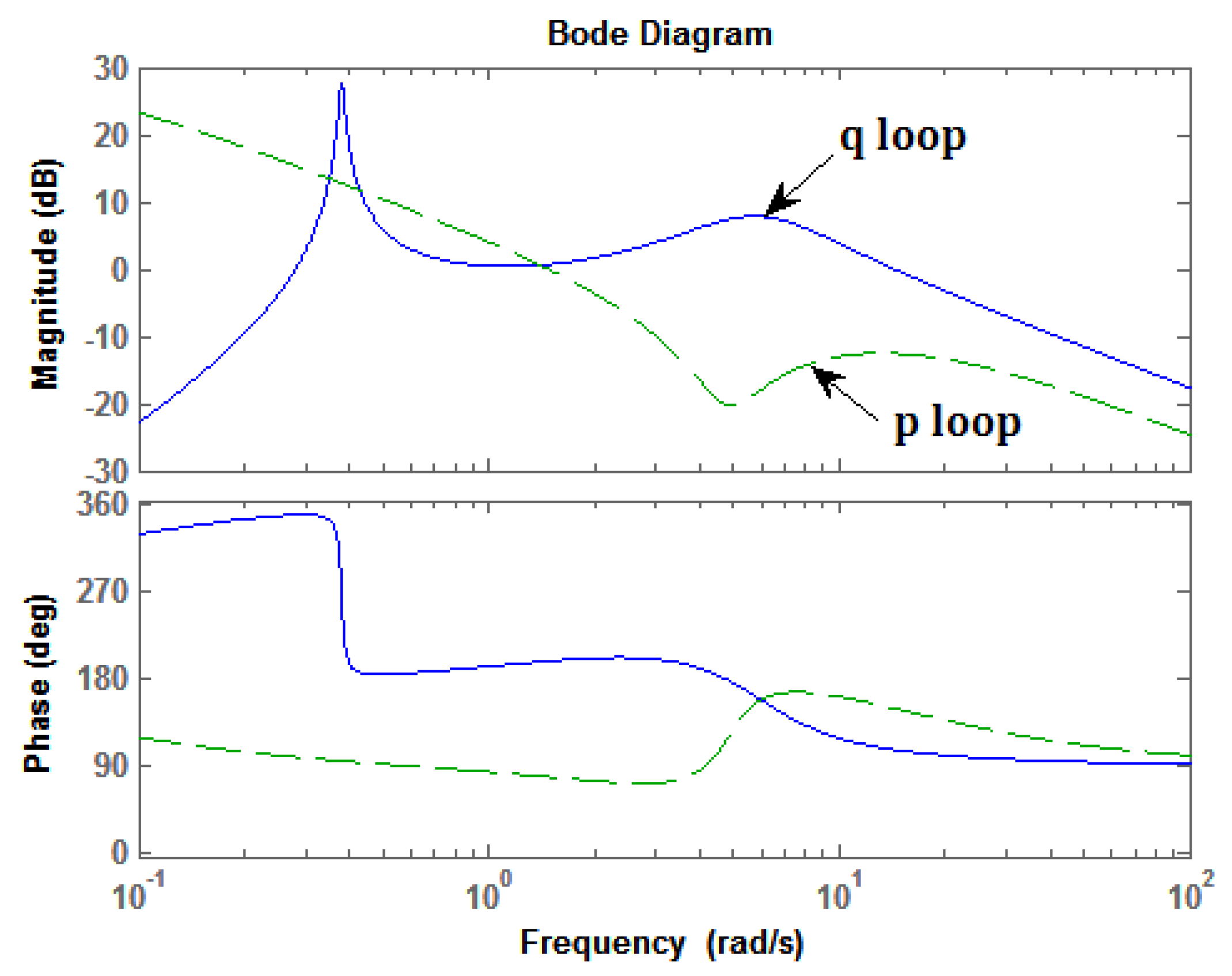
![Aerospace 01 00001 i006]() The reader will recognize typical modal characteristics in Equations (4) and (5), i.e., short period, phugoid, roll subsidence, spiral, and Dutch-roll modes [20]. Also note the non-minimum phase zero in Equation (5), not uncommon in such transfer functions [21].Figure 2 shows the Bode diagrams of the transfer functions of Equations (4) and (5), indicating relative orders of 1 (−20 dB/dec magnitude slopes beyond 10 rad/s).Figure 2. Bode Diagrams for the Transfer Functions of Equations (4) and (5).
The reader will recognize typical modal characteristics in Equations (4) and (5), i.e., short period, phugoid, roll subsidence, spiral, and Dutch-roll modes [20]. Also note the non-minimum phase zero in Equation (5), not uncommon in such transfer functions [21].Figure 2 shows the Bode diagrams of the transfer functions of Equations (4) and (5), indicating relative orders of 1 (−20 dB/dec magnitude slopes beyond 10 rad/s).Figure 2. Bode Diagrams for the Transfer Functions of Equations (4) and (5).![Aerospace 01 00001 g002]()
- (2)
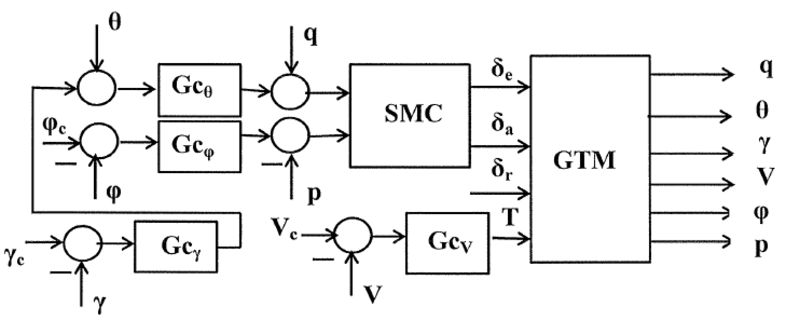
- The control structure to be used is shown in simplified form in Figure 3. Note that no yaw control system is to be created. In terms of pilot control of a full-scale aircraft, the system of Figure 3 would define flight-path control with the cockpit column, roll-rate control with the wheel, auto-throttles controlling airspeed, with bare-airframe dynamics in response to pedal inputs.Figure 3. The control system architecture.
![Aerospace 01 00001 g003]()
- (3)
- The sliding manifolds for the q and p loops, as interpreted in the frequency domain can be given by
![Aerospace 01 00001 i007]() The simplicity of these compensators should be noted. To accommodate the non-minimum phase characteristics of Equation (5), “regulated variables” were employed for the feedback variable in the p loop p(t) + 0.5r(t). Regulated variables were also used in the study of [22]. The gains shown in Equations (6) and (7) result in crossover frequencies of 20 rad/s. The author would point out that this value is reasonable for a 5% scaled aircraft.
The simplicity of these compensators should be noted. To accommodate the non-minimum phase characteristics of Equation (5), “regulated variables” were employed for the feedback variable in the p loop p(t) + 0.5r(t). Regulated variables were also used in the study of [22]. The gains shown in Equations (6) and (7) result in crossover frequencies of 20 rad/s. The author would point out that this value is reasonable for a 5% scaled aircraft.![Aerospace 01 00001 i008]()
- (4)
- By introducing initial conditions of 5/57.3 rad/s in the q-loop and −5/57.3 rad/s in the p-loop sliding behavior was verified. That is, “reaching” and “sliding” behavior was noted along with “infinite frequency” switching in the outputs of the signum elements. Figure 4 shows the reaching and sliding behavior in the p loop. Note that for sliding behavior, the numerator of Equation (7) is zero, i.e., p(t) = −6φ(t) on the sliding surface [23].Figure 4. Reaching and sliding behavior in the p loop.
![Aerospace 01 00001 g004]()
- (5)
- A boundary layer was included in the q and p loops to eliminate the high-frequency switching characteristic of SMC systems. The signum elements in the q and p loops were removed. As in other applications of the methodology, e.g., [13], no saturation elements were included. This leads to an accurate description of the methodology as pseudo-sliding mode control.
- (6)
- Actuator dynamics were next included. Due to the relative high-frequency bandwidth of the actuators, instability was avoided in this case. Nonetheless, asymptotic observers were created for the q and p loops to ensure robustness in the presence of the actuator dynamics. A single observer was utilized with inputs consisting of φ, θ, ψ, p, q, r and the outputs of all the inner-loop compensators. The eigenvalues were selected as λ = −75, −75.1, −75.2,…,−75.8, just beyond the actuator bandwidths of 62.8 rad/s.
- (7)
- Hedge dynamics were created in the q and p loops as follows:
![Aerospace 01 00001 i009]() where ucq and ucp are the output of the elements in Equations (6) and (7).
where ucq and ucp are the output of the elements in Equations (6) and (7).![Aerospace 01 00001 i010]()
- (8)
- Rate feedback loops were included in the q and p loops as follows:
![Aerospace 01 00001 i009]()
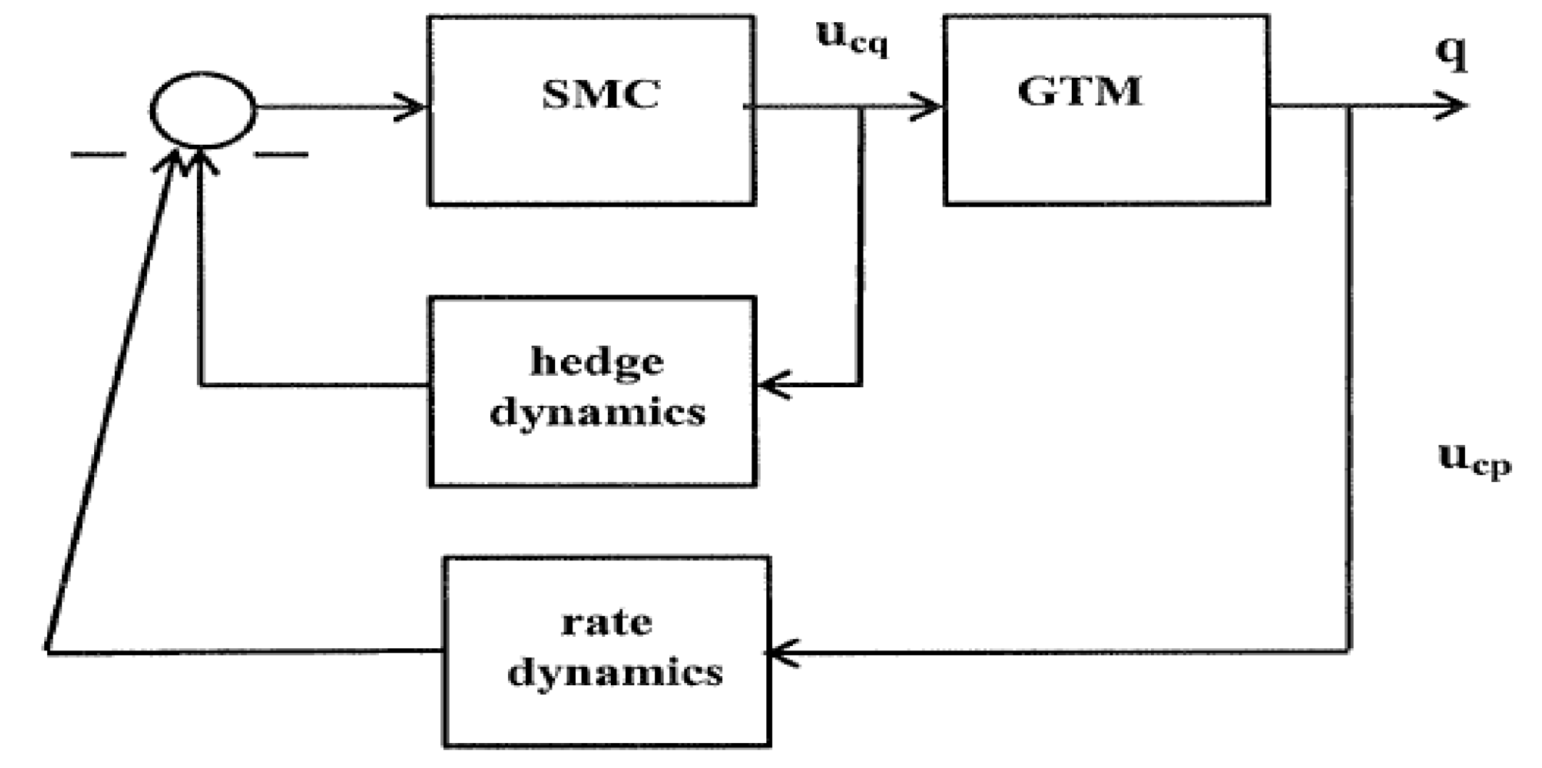
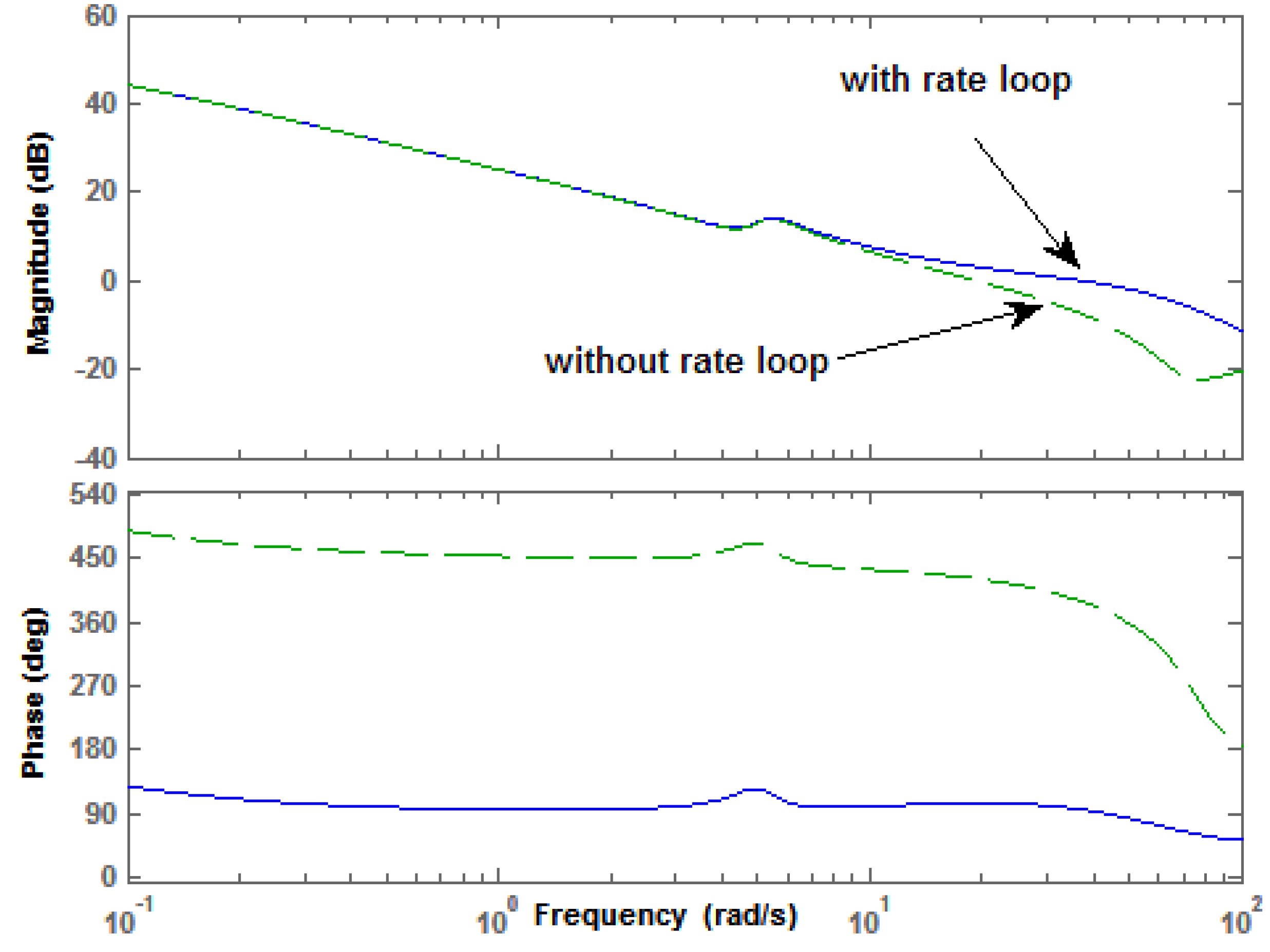
![Aerospace 01 00001 i012]() Figure 5 shows the manner in which the hedge and rate-feedback dynamics were employed, in this case, for the q loop. As an example, Figure 6 shows the result of adding the rate feedback loop to the loop transmission of the p loop. The phase difference in Figure 6 merely represents a 360 deg shift. A significant reduction in phase lag at high frequency can be seen.Figure 5. Hedge and rate dynamics placement.
Figure 5 shows the manner in which the hedge and rate-feedback dynamics were employed, in this case, for the q loop. As an example, Figure 6 shows the result of adding the rate feedback loop to the loop transmission of the p loop. The phase difference in Figure 6 merely represents a 360 deg shift. A significant reduction in phase lag at high frequency can be seen.Figure 5. Hedge and rate dynamics placement.![Aerospace 01 00001 g005]() Figure 6. Effect of rate-loop closure in loop transmission of p loop.
Figure 6. Effect of rate-loop closure in loop transmission of p loop.![Aerospace 01 00001 g006]()
- (9)
- For the purposes of this study, two flight conditions were considered, both at sea level, one at 110 ft/s and one at 220 ft/s. The asymptotic observers were scheduled with respect to these flight conditions.


4. Design of Outer-Loop Compensators

5. Computer Simulation of the Design
5.1. Sensor Noise and Unmodeled Time Delays
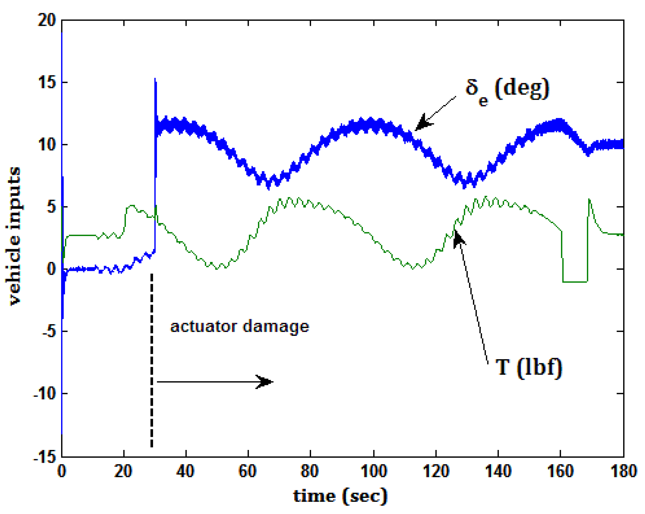
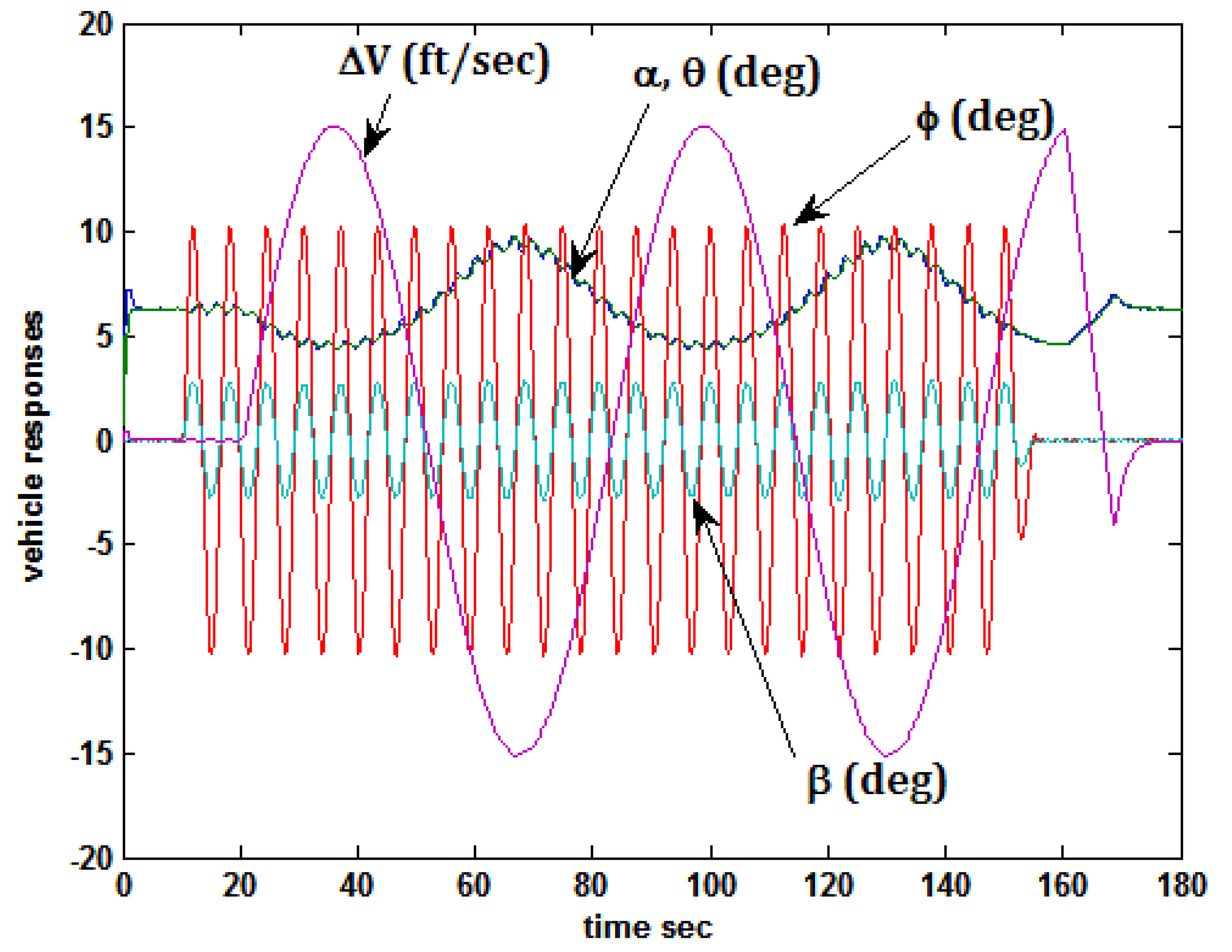
5.2. Task 1 and Actuator Damage
- (1)
- Command flight path angle γ = 0 deg.
- (2)
- Command velocity Vc = 110 ft/s
- (3)
- Command velocity perturbations around trim ΔVc = 15 sin(0.1 t) ft/s
- (4)
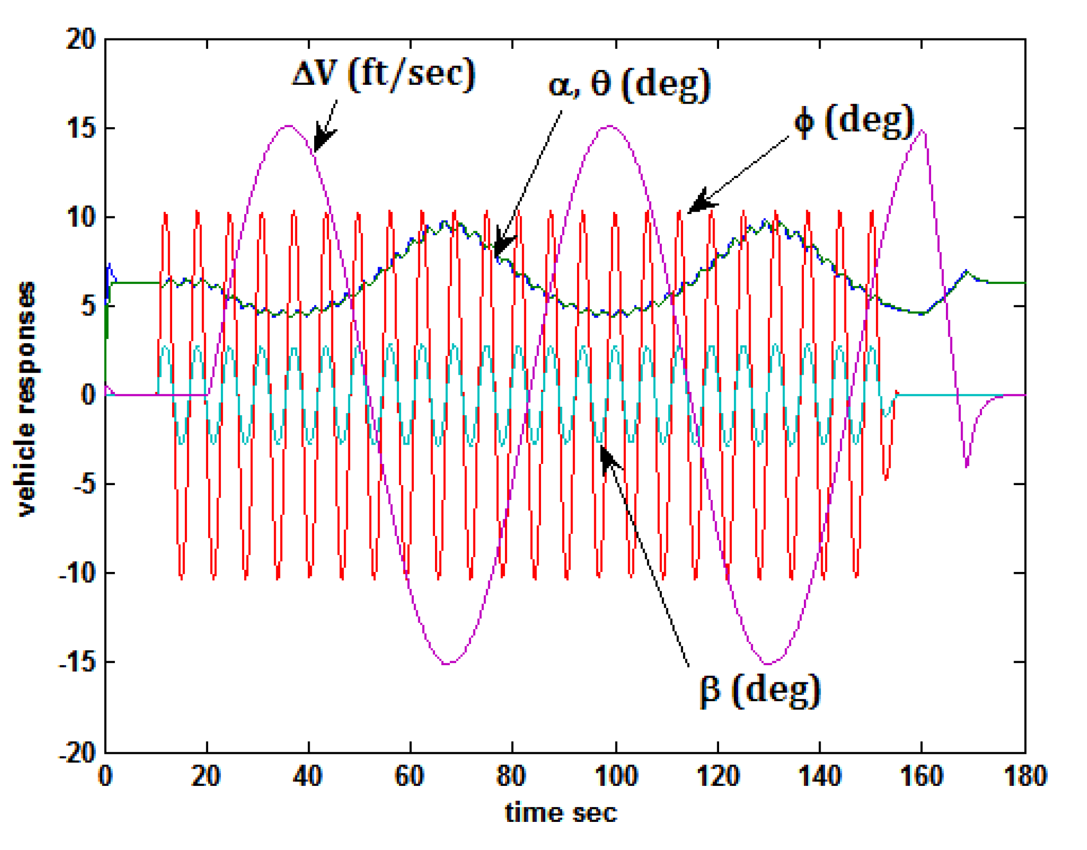
- Command roll attitude φc = 10 sin(t) deg and simultaneous rudder input δr = 5 sin(t) deg. The roll and rudder commands were deliberately designed to produce positive (negative) sideslip β, with positive (negative) roll attitude φ. These inputs were included to excite the nonlinearities in the vehicle model. While decidedly atypical pilot inputs, they have been seen in piloted simulations involving crosswind landings [24].


5.3. Task 2 and Actuator Damage

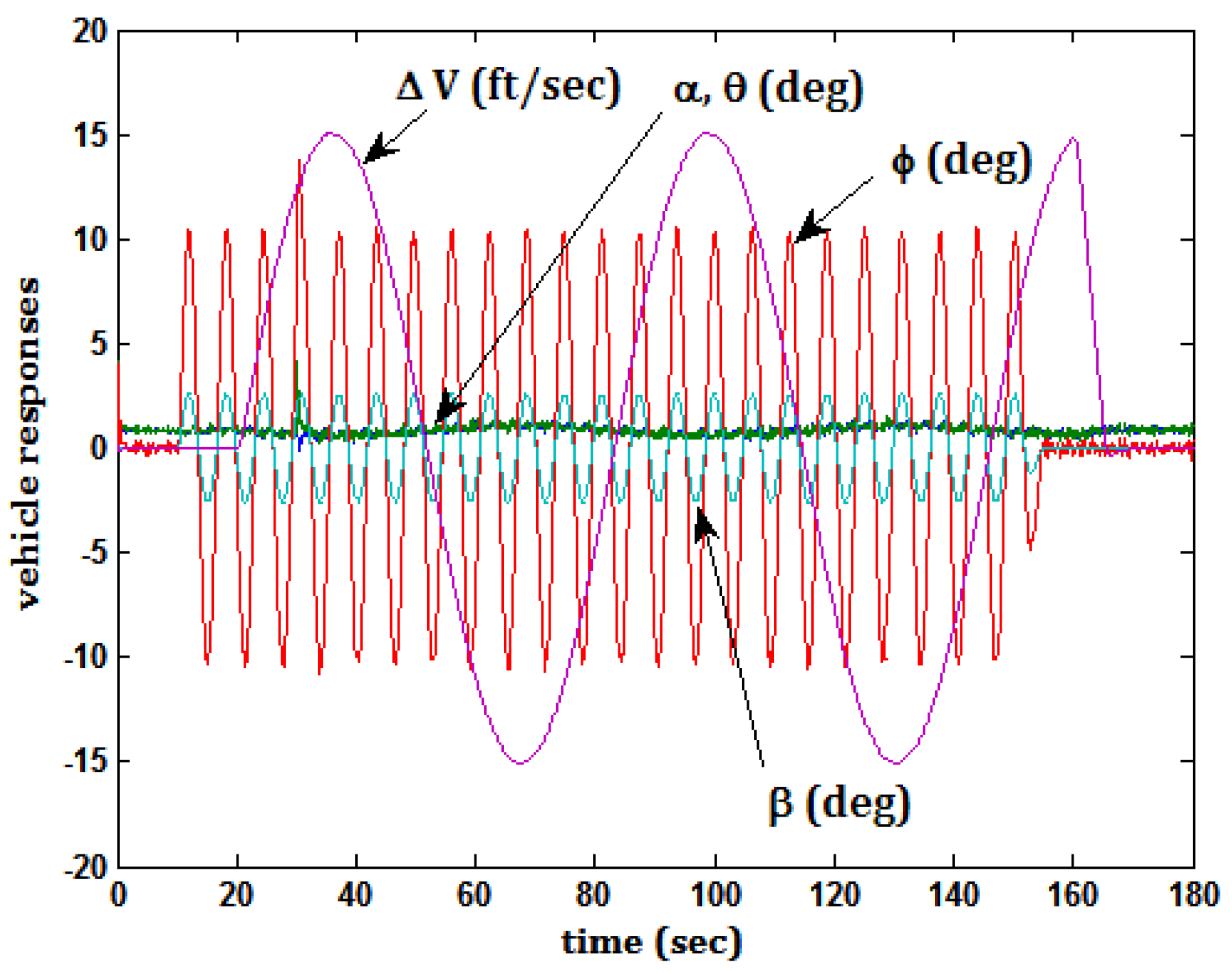
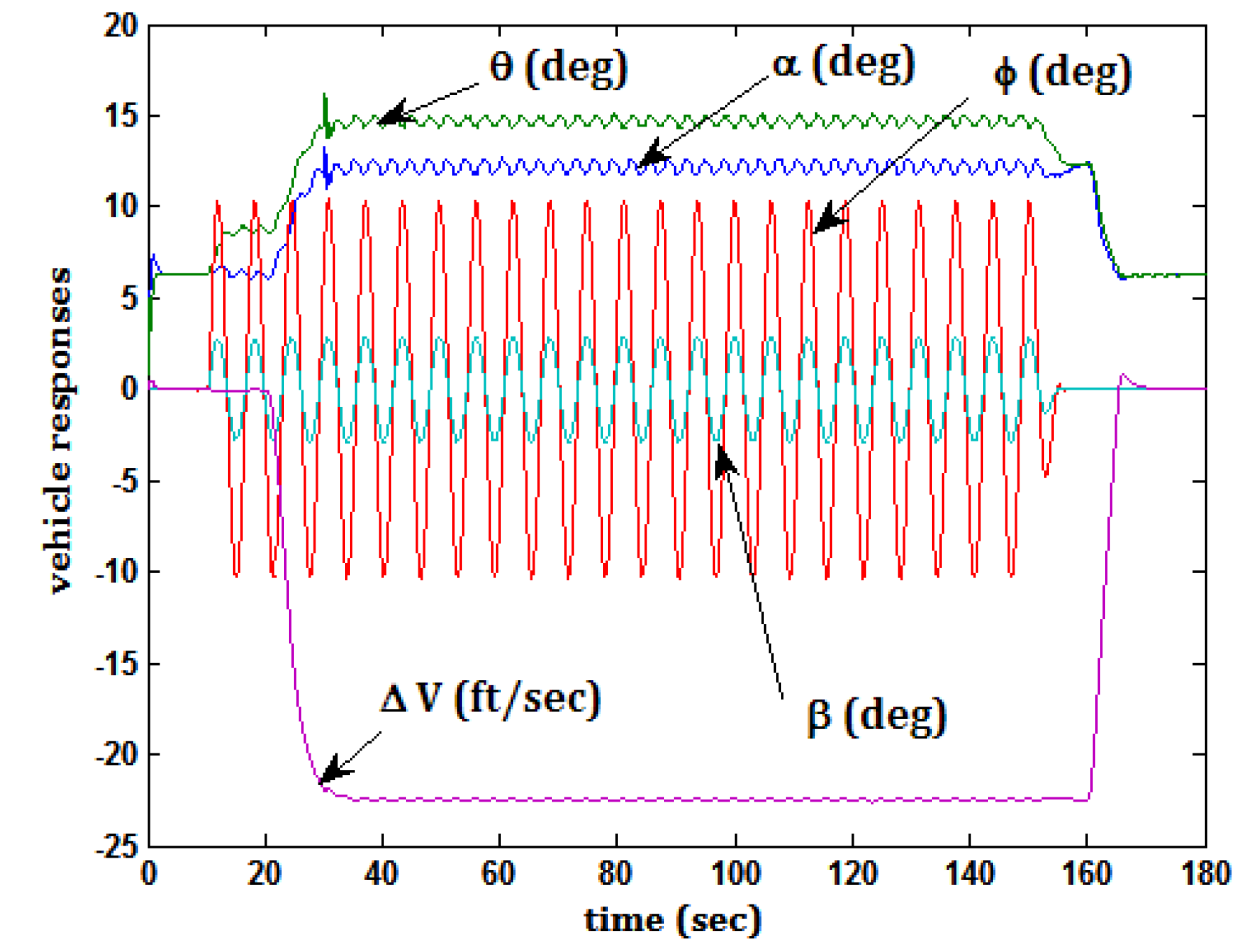
5.4. Task 3 and Actuator Damage
- (1)
- Command flight path angle γ = 2.5 deg.
- (2)
- Command velocity Vc = 110 ft/s
- (3)
- Command velocity perturbation around trim ΔVc = −22.5 ft/s
- (4)
- Command roll attitude φc = 10 sin(t) deg and simultaneous rudder input δr = 5 sin(t) deg.

5.5. Task 4 and Actuator Damage
- (1)
- Command velocity perturbation around trim ΔVc = −7.5 ft/s
- (2)
- Air density in the vehicle model was set to a value appropriate for an altitude of 10,000 ft (ρ = 0.0017556 slugs/ft3). The author is aware that the vehicle in question was not intended to operate at this altitude. The inclusion of this flight condition, however, provides an opportunity to evaluate the robustness of the SMC design.
5.6. Task 5 and Actuator Damage

6. Discussion
7. Conclusions
- (1)
- The frequency-domain based pseudo-sliding mode design procedure introduced previously in the literature can be successfully applied to the design of a highly nonlinear model of the GTM aircraft.
- (2)
- The sliding-mode design can be limited to the inner-most loops of a square control architecture in which nested control loops are closed in sequential fashion.
- (3)
- Simple loop-shaping principles are used in each of the loop closures.
- (4)
- The majority of the compensators obtained in the design are simple in form, i.e., PI controllers.
- (5)
- Computer simulations of the vehicle and control system exhibited stability and performance robustness in different flight conditions and including simulated actuator damage.
- (6)
- The overall goal of the study, to demonstrate that fundamental pilot input—system response characteristics could be preserved, with significant variations in flight condition and actuator characteristics, was met.
Appendix
GTM Vehicle Model and Actuator and Engine Characteristics
- GTM Model (as transcribed from [10])
![Aerospace 01 00001 i014]()
- Actuator Characteristics
- Elevator, aileron and rudder:where
![Aerospace 01 00001 i015]()
![Aerospace 01 00001 i016]() , amplitude limits = ±20 deg, rate limits = 300 deg/s.
, amplitude limits = ±20 deg, rate limits = 300 deg/s.
- Engine Model
- Unity dynamics
- Maximum thrust = 40 lbf


Nomenclature
| b | GTM wing span, 6.85 ft |
| c | GTM mean aerodynamic chord 0.92 ft |
| CL | Rolling moment coefficient |
| CM | Pitching moment coefficient |
| CN | Yawing moment coefficient |
| CX | X-force coefficient |
| CZ | Z-force coefficient |
| g | Acceleration due to gravity, 32.17 ft/s2 |
| Gcp | Compensation in p loop |
| Gcq | Compensation in q loop |
| GcV | Compensation in V loop |
| Gcγ | Compensation in γ loop |
| Gcθ | Compensation in θ loop |
| Gcφ | Compensation in φ loop |
| Ixx | GTM moment of inertia, 0.12 slugs/ft3 |
| Iyy | GTM moment of inertia, 4.254 slugs/ft3 |
| Izz | GTM moment of inertia, 5.454 slugs/ft3 |
| Ixz | GTM product of inertia, 0.12 slugs/ft3 |
| m | GTM mass, 1.54 slugs |
| p | Roll rate (rad/s) |
| q | Pitch rate (rad/s) |
| r | Yaw rate (rad/s) |
| S | GTM wing area, 5.9 ft2 |
| ucp | Output of Gcp (rad) |
| ucq | Output of Gcq (rad) |
| V | Velocity (ft/s) |
| ΔV | Change in velocity from trim value, ft/s |
| ΔVc | Change in velocity command from trim value, ft/s |
| xcg | GTM center of gravity position, 0.15 ft |
 | GTM reference center of gravity position, 0.25 ft |
| α | Angle of attack (rad) |
| β | Angle of sideslip (rad) |
| γ | Angle of flight path (rad) |
| δa | Aileron deflection (rad) |
| δc | Actuator command (rad) |
| δe | Elevator deflection (rad) |
| δr | Rudder deflection (rad) |
| θ | Pitch attitude (rad) |
| ρ | Air density (slugs/ft3) |
| φ | Roll attitude (rad) |
| ψ | Heading (rad) |
Conflicts of Interest
References
- Newman, R. Thirty Years of Airline Loss-of-Control Mishaps. In Proceedings of the AIAA Modeling and Simulation Technologies Conference, Minneapolis, MN, USA, 13–16 August 2012.
- The Boeing Company. Statistical Summary of Commercial Jet Airplane Accidents Worldwide Operations 1959-2008. July 2009. Available online: http://www.airsafe.com/events/models/statsum2008.pdf (accessed on 23 October 2013).
- Wong, C.; Gregory, I.; Cao, C. L1 Adaptive Control with Output Constraints Applied to Flight Envelope Limiting. In Proceedings of the AIAA Modeling and Simulation Technologies Conference, Minneapolis, MN, USA, 13–16 August 2012.
- Belcastro, C.; Kwatny, H.; Balas, G. Validation of Safety-Critical Systems for Aircraft Loss-of-Control Prevention and Recovery. In Proceedings of the AIAA Modeling and Simulation Technologies Conference, Minneapolis, MN, USA, 13–16 August 2012.
- Cunningham, K.; Foster, J.V.; Morelli, E.A.; Murch, A.M. Practical Application of a Subscale Transport aircraft for Flight Research in Control Upset and Failure Conditions. In Proceedings of the AIAA Atmospheric Flight Mechanics Conference, Honolulu, HI, USA, 18–21 August 2008.
- Hedrick, J.K.; Gopalswamy, S. Nonlinear flight control design via sliding methods. J. Guid. Control Dyn. 1990, 13, 850–858. [Google Scholar] [CrossRef]
- Shtessel, Y.; Buffington, J.; Banda, S. Multiple timescale flight control using reconfigurable sliding modes. J. Guid. Control Dyn. 1999, 22, 873–883. [Google Scholar] [CrossRef]
- Levant, A.; Pridor, A.; Gitizadeh, R.; Yaesh, I.; Ben-Asher, J.Z. Aircraft pitch control via second-order sliding technique. J. Guid. Control Dyn. 2000, 23, 586–594. [Google Scholar] [CrossRef]
- Singh, S.N.; Steinberg, M.L.; Page, A.B. Nonlinear adaptive and sliding mode flight path control of F/A-18 model. IEEE Trans. Aerosp. Electron. Syst. 2003, 39, 1250–1262. [Google Scholar] [CrossRef]
- Hess, R.A.; Wells, S.R. Sliding mode control applied to reconfigurable flight control design. J. Guid. Control Dyn. 2003, 26, 452–462. [Google Scholar] [CrossRef]
- Xu, H.; Mirmirani, M.D.; Ioannou, P.A. Adaptive sliding mode control design for a hypersonic flight vehicle. J. Guid. Control Dyn. 2004, 27, 829–838. [Google Scholar]
- Hess, R.A.; Vetter, T.K.; Wells, S.R. Design and evaluation of a damage-tolerant flight control system. J. Aerosp. Eng. 2005, 219, 341–359. [Google Scholar]
- Hess, R.A. frequency domain-based pseudosliding mode flight control design. J. Aircr. 2012, 49, 2077–2088. [Google Scholar] [CrossRef]
- Gregory, I.M.; Xargay, E.; Cao, C.; Hovakimyan, N. L1 Adaptive Control Law in Support of Large Envelope Modeling Work. In Proceedings of the 1st CEAS Specialists’ Conference on Guidance, Navigation & Control, (EuroGNC 2011), Munich, Germany, 13-15 April 2011; pp. 1210–1217.
- Kwatny, H.G.; Dongmo, J.-E.T.; Chang, B.-C.; Bajpai, G.; Yasar, M.; Belcastro, C. Nonlinear analysis of aircraft loss of control. J. Guid. Control Dyn. 2013, 36, 149–162. [Google Scholar] [CrossRef]
- McRuer, D.T. Aviation Safety and Pilot Control: Understanding and Preventing Unfavorable Pilot-Vehicle Interactions; National Academy Press: Washington, DC, USA, 1997. [Google Scholar]
- Gibson, T.E.; Annaswamy, A.M.; Kenny, S.P. Adaptive control of Generic Transport Model with Modelled Failures; ACC/TM-2009-01; Active Adaptive Controls Laboratory, Massachusetts Institute of Technology: Cambridge, MA, USA, January 2009; Available online: http://www.mit.edu/~tgibson/AAC200901.pdf (accessed on 23 October 2013).
- Gorder, P.J.; Hess, R.A. Sequential loop closure in design of robust rotorcraft flight control systems. J. Guid. Control Dyn. 1997, 20, 1235–1240. [Google Scholar] [CrossRef]
- Hess, R.A.; Gama, G. Frequency domain, pseudo-sliding mode control system for a flexible aircraft. J. Aerosp. Eng. 2007, 221, 707–717. [Google Scholar]
- Schmidt, D.K. Modern Flight Dynamics; McGraw-Hill: NewYork, NY, USA, 2012; Chapter 10. [Google Scholar]
- Heffley, R.K.; Jewell, W.F. Aircraft Handling Qualities Data; NASA Contractor Report, NASA CR-2144; NASA: Washington, DC, USA, December 1972. [Google Scholar]
- Hess, R.A.; Cama, G. Flight control system design for inherent damage tolerance. J. Aircr. 2008, 45, 2024–2035. [Google Scholar] [CrossRef]
- Utkin, V.I.; Guldner, J.; Shi, J. Sliding Mode Control in Electro Mechanical Systems; Taylor and Francis: London, UK, 1999; Chapter 1. [Google Scholar]
- Hess, R.A. Metrics for the evaluation of pedal force/feel systems in transport aircraft. J. Aircr. 2008, 45, 651–662. [Google Scholar] [CrossRef]
- Gregory, I.M.; Xargay, E.; Cao, C.; Hovakimyan, N. Flight Test of L1 Adaptive Control Law: Offset Landings and Large Flight Envelope Modeling Work. In Proceedings of the AIAA Guidance, Navigation, and Control Conference, Portland, OR, USA, 8–11 August 2011.
© 2013 by the authors; licensee MDPI, Basel, Switzerland. This article is an open access article distributed under the terms and conditions of the Creative Commons Attribution license (http://creativecommons.org/licenses/by/3.0/).
Share and Cite
Hess, R.A. Robust Flight Control Design to Minimize Aircraft Loss-of-Control Incidents. Aerospace 2014, 1, 1-17. https://doi.org/10.3390/aerospace1010001
Hess RA. Robust Flight Control Design to Minimize Aircraft Loss-of-Control Incidents. Aerospace. 2014; 1(1):1-17. https://doi.org/10.3390/aerospace1010001
Chicago/Turabian StyleHess, Ronald A. 2014. "Robust Flight Control Design to Minimize Aircraft Loss-of-Control Incidents" Aerospace 1, no. 1: 1-17. https://doi.org/10.3390/aerospace1010001
APA StyleHess, R. A. (2014). Robust Flight Control Design to Minimize Aircraft Loss-of-Control Incidents. Aerospace, 1(1), 1-17. https://doi.org/10.3390/aerospace1010001