Abstract
One of the research areas in radio-frequency identification (RFID) systems is the reduction of the identification processing time for a number of tags within an RFID reader recognition region. In the last decade, many research results regarding anticollision algorithms have been presented in the literature. Most of them are tree-based protocols. However, it is important for tree-based protocols to enhance stability and system throughput, since they may face long identification delays when the network density is high. In this study, we present a highly efficient predetection tree-based algorithm to achieve more efficient tag identification performance. Our proposed mechanism can effectively reduce both collisions and idle cycles by exploiting the predetection technique and adjustable slot size mechanism. The simulation results show that the proposed mechanism can effectively improve tag identification time performance by around 29.9% to 64.8% over previous techniques. Further, the number of query cycles, number of collisions, and total number of slots are reduced compared to previous predetection-based protocols. It is also observed that the proposed scheme can have good performance in large-scale RFID systems.
1. Introduction
Radio-frequency identification (RFID) is an automatic technology that is widely used in modern industrial practical applications, such as inventory management [1], object identification and tracking, supply-chain management, and wireless sensor networks [2,3]. It also plays an important role in realizing the Internet of Things concept [4]. Traditional identification systems, such as barcodes and smart-card systems, are inefficient at automatic identification and data collection due to their read rate, visibility, and contact limitations. RFID systems, on the other hand, provide fast and reliable communication without the requirement of physical visibility or contact between readers and tags. Based on these advantageous features, today’s RFID technology goes beyond identification of objects and is being used for localization [5,6] and sensing applications [7]. In addition, more and more battery-less tags can be augmented with sensors, so that tags can send not only their unique IDs, but also sensed data to readers [8].
One of the areas of research in this field is the reduction of the identification processing time for a given number of tags within an RFID reader recognition zone. To achieve the goal of fast tag identification, anticollision protocols are required. An anticollision protocol aims to reduce collisions during the tag identification process. The collisions can be categorized into two types: reader collisions and tag collisions. When two or more neighboring readers inquire a tag simultaneously, reader collisions occur. As a result, the tag cannot respond with its ID to the appropriate inquiring readers. The reader collision problem can be solved easily by detecting the collisions and communicating with other readers. On the other hand, tag collisions occur when more than one tag tries to respond to a reader concurrently, which causes the reader to identify no tag. In RFID systems with low-cost passive tags, the only thing for a tag to do is to respond to the reader inquiry. Therefore, tag anticollision protocols are necessary to achieve the efficiency of identifying tag IDs in RFID systems.
Many research results for reducing identification collisions have been presented in the literature. These tag identification mechanisms can be classified into two main categories, the Aloha-based anticollision scheme [9,10,11] and the tree-based scheme [12,13,14,15,16,17,18,19,20,21,22,23]. In the Aloha-based scheme, the RFID reader creates a frame with several time slots, and then adds the frame length to the inquiry message sent to the tags in its recognition region. Tags respond to the reader’s inquiry by choosing a random time slot. Tags that respond simultaneously in the same time slot cannot be recognized by the reader because of the collisions. Thus, the reader needs to send inquiries repeatedly until all tags are identified, which makes the Aloha-based scheme suffer long processing times in identifying large-scale RFID systems [20].
In a tree-based scheme, such as the query tree (QT) algorithm [12,13], Improved Bit-by-bit Binary-Tree (IBBT) [14], binary tree splitting protocol [15], tree working algorithm [16,17], and Intelligent Query Tree (IQT) [18], RFID readers use a scheme similar to a binary search algorithm to recognize the tags. Once the tags collide, the readers split the collided tags into two subgroups and repeat the process until they recognize the IDs of tags without collisions. Therefore, readers using the tree-based scheme are able to identify all tags. Choi et al. [14] proposed a fast anticollision algorithm called the Improved Bit-by-bit Binary-Tree algorithm (IBBT) for ubiquitous identification systems and evaluated its performance along with three older schemes. The reader in the IBBT algorithm requests all bits of tag IDs. After the reader receives responses from tags, it saves the results of each receiving bit. Therefore, the reader knows which bits have collided, and it sequentially sends the request only for the collided bits to tags in a bit-by-bit fashion. Myung et al. [13] proposed the adaptive memoryless tag anticollision protocol, which is an extended scheme based on the query tree protocol. The reader in this proposed approach uses not only a queue to maintain prefixes, but also an additional candidate queue for maintaining both prefixes of identified nodes and no-response nodes of the last identification process. As a result, when the number of tags is increased, the collision period can be shortened. Sahoo et al. [18] proposed an intelligent query tree algorithm (IQT), which modified the query tree protocol for scenarios where the tags have some common prefix. In [19], Zhou et al. considered scenarios where multiple readers can be deployed in a region to improve the coverage. In such environments, multiple readers can perform tag reading concurrently, and collisions may occur when multiple readers are used within a close vicinity. They discussed the problem of slotted scheduled access of RFID tags and developed centralized algorithms in a slotted time model to read all the tags. In addition to the proof of NP-hardness, they also proposed approximation algorithms for single-channel cases and heuristic algorithms for multiple-channel cases.
Unlike Aloha-based protocols that cause the tag starvation problems, tree-based protocols deliver 100% guaranteed read rates, but the identification delay is relatively long due to the large amounts of collisions and idle time. Therefore, collision resolution and idle time elimination become the major issues in tree-based anticollision protocols. Jia et al. [24] proposed a collision tree (CT) algorithm, which is based on QT, aiming to eliminate collisions and idle time. The proposed algorithm both generates prefixes and splits tags according to the first collide bit, which eliminates the idle slots effectively. Lai et al. [25] proposed an optimal binary tracking tree protocol that employs a bit estimation algorithm to split tags into small sets and then uses a binary tracking tree method to quickly identify tags. Yan et al. [26] proposed a hybrid anticollision algorithm, called anticollision protocol based on improved collision detection, to reduce tag collisions. Their approach employs the idea of bit-tracking technology and dual-prefix matching into a collision arbitration mechanism in the RFID system. Landaluce et al. [27] presented a bit window procedure to manage the length of tags’ bit streams in order to reduce the energy consumption in collisions. They modified both QT and CT protocols by adding the bit window procedure to produce the query window tree protocol and the collision window tree protocol. However, these algorithms have complicated implementation and increase identification delay.
Ryu et al. [20] proposed a hyper-hybrid query tree protocol (HQT), aiming to reduce identification delays. The proposed protocol reduces identification delay by eliminating collisions and idle time. To reduce collisions, a quarternary query tree is used instead of a binary tree. In the quaternary query tree mechanism, the prefix string of a collided query will be expanded by two bits instead of one bit in the QT protocol. As a result, the collision cycles will be reduced substantially, but idle time will increase as a side effect. To eliminate idle time, they introduced a slotted back-off mechanism to reduce unnecessary query commands. When a tag responds to a reader, its back-off time is set from the two bits following the prefix of tag ID to the query string sent by the reader. When a collision occurs, the reader can partially detect to which subtrees the tags belong, and unnecessary queries can potentially be reduced. However, the slotted back-off mechanism in the HQT protocol cannot check the idle cycles between busy slots. To solve the problem, a hybrid hyper query tree algorithm (H2QT) was proposed by Kim et al. [21]. The protocol aims to reduce the idle cycle by using a different slotted back-off mechanism. When a tag responds to a reader, its back-off time is determined from the three bits that follow the prefix of tag ID to the query string. Unlike the HQT protocol, the back-off mechanism in the H2QT protocol counts the number of 1’s in the three bits and uses this number to select a response slot in the tag response window. As a result, idle cycles can be reduced substantially. However, collision cycles cannot be reduced by using the back-off mechanism in the H2QT protocol and the identification delay is still long.
In a preliminary work [22], we addressed the key design aspect of using a predetection-based technique called the Pre-Detection Broadcasting Query Tree (PDBQT) protocol, to eliminate those unnecessary idle cycles and avoid collision cycles. The reader in the PDBQT protocol allocates some tiny predetection slots for tags to respond in order to reveal the distribution of tags. Then, by knowing the distribution of tags, only existing tags will respond in the corresponding response time slots of the following tag response cycle. As a result, no idle slots are wasted and collision slots can be reduced.
In this paper, we extend the previous work by investigating the optimal assignment of tag response time slots in the predetection scheme after collecting the tag distribution information. The proposed identification scheme will (1) reduce the communication overhead between reader and tags during the predetection process, (2) reduce the tag response time as much as possible, and (3) complete the tag identification process as quickly as possible.
Our contributions may be summarized as follows:
- This paper introduces a tag identification problem for RFID systems, that readers collect tags’ IDs with the goal of minimizing transmission completion time. We exploit the predetection scheme to reveal the distribution of tags’ IDs, and no idle time slots are wasted.
- Then, by knowing the distribution of tags’ IDs, the reader can allocate the appropriate time slots and broadcast the arranged information to tags with minimum communication overhead.
- Simulation results validate that its performance is better than previously proposed predetection solutions.
The rest of this paper is organized as follows: in Section 2, we describe the idea and function of the predetection scheme as the preliminary work of this study. Section 3 introduces our proposed predetection-based tag identification technique. In Section 4, we evaluate the performance of our proposed scheme, the Efficient Pre-Detection–based Query Tree (EPDQT) algorithm. Performance comparisons and analyses are also given. Finally, we conclude the paper in Section 5.
2. Predetection-Based Scheme
The main idea of our anticollision algorithm is to understand the distribution of tag IDs as much as possible. When the distribution is realized, the reader will send this information to tags so that each tag is able to realize the appropriate time slot to respond in the response cycle. As a result, different tags will then respond to the reader in different time slots, which can reduce collisions substantially. In addition, no empty slot occurs, since the reader allocates optimal time slots for tags to respond.
To do so, we propose a predetection-based scheme to reveal the distributions of tag IDs. Recall that all passive tags follow the request-respond mode, since they cannot initiate communication between themselves and readers. Therefore, the tag identification process can be viewed as several iterations of two operations: the reader request and the tag response. In our predetection scheme, after the reader request operation (i.e., the reader sends the request command or prefix string to tags), the operations in the tag response cycle are composed of three phases: (1) the predetection phase, (2) the broadcasting phase, and (3) the tag response phase, as shown in Figure 1. The purposes or functions of these three phases can be described as follows:

Figure 1.
The tag response cycle in the predetection scheme.
- Predetection phase: The purpose of the predetection phase is to collect information about tags to understand the overall distribution of tags. To do so, the reader allocates many tiny time slots, and each tiny slot will be responsible for collecting tag information for a particular group. These tiny slots are allocated for collecting tag’s information, instead of tag’s ID. Once the time slot has information available, reader can understand the distribution of tags for that particular group, and this distribution information will help the reader for determining if the time slot is needed to receive tag’s ID during the tag response phase. There are 2n tiny time slots numbered from 0 to 2n − 1 and each time slot can be represented as an n-bit binary string. Once a tag matches the prefix string, it will respond a message to the tiny slot that has the same label as next n-bit of tag’s ID. The message of tags to respond depends on the width of each tiny time slot. In general, the width of these slots is smaller than the length of the tag’s ID, in order to reduce the communication overhead. After receiving responses from tags, the reader can recognize the status of each tiny slot: idle, success, or collision. When no tag responds, it leads to an idle state. When only one tag responds, it is recognized as a success state. When more than one tag tries to respond to the reader’s query, the reader can recognize it as a collision state.
- Broadcasting phase: After the predetection phase, the reader can encode the state of each time into bit 0 or 1. The success state is encoded into bit 1, and both idle and collision states are encoded into bit 0. Then, in the broadcasting phase, the reader sends the binary string representing the status of each time slot to tags, so that those tags with IDs that match the prefixes can realize how many time slots are allocated and which are available to respond with their IDs.
- Tag response phase: After receiving the broadcasted binary string representing the status of each tiny slot in the predetection phase, each tag is able to realize the appropriate time slot to respond with its ID. Note that each bit in the received 2n-bit binary string represents the status of the corresponding tiny slot in the predetection phase. If it is bit 1, then only one tag is detected and its ID can be successfully identified by the reader. For this purpose, the reader will allocate a long time slot to receive tags’ IDs. On the other hand, if it is bit 0, then an idle cycle or collision cycle is detected. The reader will not allocate any time slot to receive IDs for both cases. As a result, the tag responses can be arranged into a sequence of time slots and collisions or idle slots can be avoided.
In our preliminary work [22], we proposed an anticollision scheme called the Pre-Detection Broadcasting Query Tree (PDBQT) protocol, which is based on the aforementioned predetection scheme. In the PDBQT protocol, the reader will allocate four tiny slots, say 00, 01, 10, and 11, in the predetection phase for tags to respond. Then, by using the quaternary query tree mechanism, each tag that matches the reader’s query prefix string responds on the time slot that is determined from the next two bits of its tag ID. In order to reduce communication overhead, only a four-bit random number is responded to by a tag instead of the whole tag ID. If there is no tag response in a time slot, the reader can realize that it is an idle slot, and no time slot will be allocated in the tag response phase. If the receiving four bits can be identified correctly, the reader can realize that the time slot is a success slot, and the corresponding time slot will be allocated in the tag response phase to receive the whole tag ID. If more than one tag responds, since each tag responds to a four-bit random number, a collision slot can be identified if different random numbers are transmitted to the reader. Since the probability of transmitting same random number by different tags is low, the reader can identify a collision with high accuracy when multiple tags respond. As a result, there is a high possibility that the reader can realize the exact distribution of tag IDs.
As mentioned, in the predetection phase, those tags that match the prefixes respond on the time slot that is determined from the next two bits, which follow the prefixes of their IDs identical to the query string. The reader uses a four-bit binary string representation to indicate the status of time slots and broadcasts the status to tags. After broadcasting, those tags with IDs identical to the query string tag can realize the exact time slot to respond by checking the corresponding bit of the received four-bit binary string. The tag can respond with its ID in the upcoming tag response phase if the corresponding bit in the broadcasting four-bit string is 1. Otherwise, no tag response occurs. For those tags that can respond in the tag-response phase, the exact time slot to respond can also be obtained by counting the number of 1’s in the broadcasting four-bit string from the start bit to the corresponding bit that represents the next two bits to the prefixes of their IDs. Consider the example in Figure 2. The tag responding on the 11 time slot in the predetection phase is aware that its ID can be responded to by the reader only on the third time slot, since the received four-bit broadcasted string is 1101, and it is the third 1 from the beginning bit to the corresponding bit.
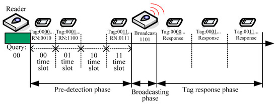
Figure 2.
The tag response cycle of our preliminary work.
3. Proposed Anticollision Scheme
Recall that the previous proposed PDBQT protocol can eliminate all idle cycles. However, it is possible for different tags to respond to the same four-bit random numbers in the same time slot. In such a situation, the collision will be identified in the tag response phase instead of the predetection phase. As a result, more time slots will be needed to identify those collision tags and the time needed to identify all tags will be prolonged. In this paper, we propose a highly efficient algorithm, called the Efficient Pre-Detection based Query Tree (EPDQT) algorithm, to improve the performance in terms of increasing system throughput and minimizing identification delay.
3.1. System Model of EDPQT Scheme
In this section, we will describe the system model of our proposed EDPQT scheme. Suppose there are t tags in the reader field and each tag has the same length of m-bit ID, which can be denoted as a binary string b1b2...bm, where each bi is either 0 or 1. Since our scheme is based on the predetection mechanism, the tag response cycle is composed of three phases: predetection phase, broadcasting phase, and tag response phase, as mentioned above. In the predetection phase, the number of time slots depends on a parameter, say n, which is varied and can be defined by users when using this algorithm. After a reader sends an inquiring p-bit string (prefix), 0 ≤ p ≤ m, to tags, it allocates 2n time slots for tags to respond. Then, tags located within the reader’s close vicinity respond to the reader if the inquiring bits are the same as the first p bits of tag IDs. When a tag responds, it selects one of 2n time slots to respond, depending on the n bits following the first p bits of its tag ID, that is, bp+1bp+2...bp+n. Thus, the time slot represents the value of n bits. After determining the time slot to respond, the tag sends the (n + 1)th bit following the first p bits of its tag ID, that is, bp+n+1, to the reader. For example, if n = 2 and the tag ID is 010110, then after the reader sends a two-bit prefix string, say 01, the tag will respond with its fifth bit, which is 1, on the 01 time slot in the predetection phase, since the following two bits after the first two bits is 01. This means that in our algorithm, there is only one bit for the tag to respond in the predetection phase. Furthermore, in the tag response phase, those successfully recognized tags will send the remaining IDs, that is, bp+n+2...bm, to the reader. As a result, communication overhead can be reduced substantially. Figure 3 shows the system model of the interaction between the reader and tags in our proposed EPDQT scheme.
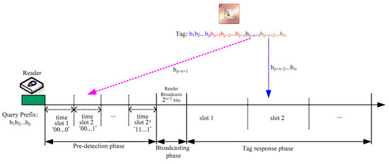
Figure 3.
The interaction between reader and tag in the Efficient Pre-Detection based Query Tree (EPDQT) scheme.
After the predetection phase is completed, the distribution of tags can be realized by collecting the status of each time slot in the predetection phase. The status of each time slot can be categorized as one of four states: idle, collision, 0-success, or 1-success. The idle state indicates that no tag matches with the prefixes. The collision state occurs when more than one tag matches with the prefixes. Then it is necessary to resolve the collisions in the upcoming query cycles. The 0-success and 1-success states indicate that the reader receives only 0 or 1, respectively, in the predetection phase. It should be noted that the 0-success state or 1-success state may occur when only one tag is matched or more than one tag is matched but returns the same bit string. The latter case will cause a collision, as many tags return their IDs on the same time slot in the tag response phase. As a result, the reader needs more cycles to identify those collided tags. It also should be noted that once the collision state has been detected, either in the predetection phase or in the tag response phase, the prefix string, along with the corresponding time slot string, will be added to a waiting queue for further inquiry by the reader. This means that the whole tag identification process will be repeated until the waiting queue is empty.
As the states of all time slots in the predetection phase are collected, each state is encoded into a two-bit pattern. The idle, 1-success, 0-success, and collision states are represented as 00, 01, 10, and 11 bit patterns, respectively. Then, in the broadcasting phase, the reader broadcasts the whole bit patterns of all time slots in the predetection phase. Since there are 2n slots allocated in the predetection phase and each slot can be encoded into a two-bit pattern, there will be a total 2n+1-bit binary string broadcasted by the reader. Each bit in the broadcasting binary string indicates whether a time slot is needed in the tag response phase. The time slots needed in the tag response phase can also be represented as an (n + 1)-bit binary string. Thus, for n = 1, there may be four time slots, which can be represented as 00, 01, 10, and 11, in the tag response phase, and for n = 2, we may have eight time slots, denoted as 000, 001, …, 111. However, not every time slot will exist in the tag response phase. In our scheme, the reader will allocate the time slots for those bits in the broadcasting binary string that have 1’s. No time slot is needed for those 0’s. For example, the reader will allocate three time slots during the tag response phase, namely 010, 100, and 111, if the broadcasting binary string is 00101001.
As the tags receive the broadcasting 2n+1-bit string, each tag will check the next (n + 1)-bit after the first p-bit of its ID to see if the corresponding bit in the broadcasted binary string is 1 or 0. The tag will respond during the tag response phase only if the corresponding bit is 1. Furthermore, the tag can also be aware of the exact time slot to respond by counting the number of 1’s in the received broadcasting string from the start bit to the corresponding bit. Again, if n = 2, tag ID is 01011010, and the prefix string is 01, then after receiving the broadcasted binary string 00101001, the tag will check the next three-bit, which is 011, after the first 01 bits of its ID to see if the corresponding bit in the broadcasted binary string is 1 or 0.
Furthermore, to accelerate the identification, we propose different procedures for some special cases where the length of a prefix query string approaches the length of tag IDs. These cases will be explained in detail in the following section.
3.2. Special Cases of the EPDQT Scheme
In our scheme, as the number of iterations grows, the length of the prefix query string also grows. This means that the value of p will increase as the identification process keeps running. In such scenarios, special procedures are needed to speed up the identification process when p is approaching m. Based on our observations, there are three possible special cases that can occur during the identification process, which can be described as follows:
- p + n = m − 1: In this case, after the predetection phase, there is no bit left for each tag to respond in the tag response phase. Thus, the reader can immediately identify the tag IDs after the predetection phase by realizing the status of each time slot in the predetection phase. Assume that the prefix string is b1b2...bp and the binary string of the corresponding time slot in the predetection phase is bp+1bp+2...bp+n. Then, when the reader realizes the status of a time slot as a 0-success or 1-success state, it can immediately identify a tag with ID as b1...bpbp+1...bp+n followed by bit 0 or bit 1, respectively. For the collision state, the reader can also identify two tags with IDs b1...bpbp+1...bp+n0 and b1...bpbp+1...bp+n1.
- p + n ≥ m: In this case, the reader will change the value of n to m − p − 1 before sending the prefix string. Then, the reader will follow the procedure described in the previous case, since now p + n = m − 1.
- p + n = m − 2: In this case, there is only one bit left for each tag to respond in the tag response phase. The reader can identify the tag IDs by verifying the results of each slot in the tag response phase. Note that there are three possible results: idle, success, and collision. For the collision case, the reader can immediately identify two tags with IDs b1...bpbp+1...bp+nbp+n+10 and b1...bpbp+1...bp+nbp+n+11.
3.3. An Example of the EPDQT Scheme
To facilitate understanding of the EPDQT algorithm, we show below an example of the identification procedure of our proposed protocol. We assume that there are eight tags with eight-bit unique IDs: tag A (with ID 00101010), tag B (with ID 00110101), tag C (with ID 00111011), tag D (with ID 10011100), tag E (with ID 11010001), tag F (with ID 11010100), tag G (with ID 11011001), and tag H (with ID 11011010). The whole process is also shown in Figure 4. The iterations of the identification process using the EPDQT protocol with n = 2 are described as follows:
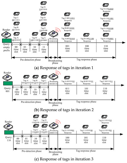
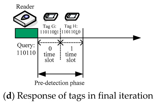
Figure 4.
An example of the identification process of our scheme with n = 2.
Iteration 1: First of all, the waiting queue is empty and the reader sends the empty-prefix to the tags and allocates four time slots for the predetection phase. All tags respond to this empty-prefix request command. In this case, tags A, B, and C respond on the 00 time slot and send bit 1 to the reader. Tag D responds on the 10 time slot with bit 0. Tags E, F, G, and H respond on the 11 time slot, both with bit 0, to the reader. After receiving the responses from tags, the reader can realize the status of four time slots in the predetection phase as 1-success in the 00 slot, idle in the 01 slot, 0-success in the 10 slot, and 0-success in the 11 slot. Thus, the broadcasting string representing the status of the time slots in the predetection phase is encoded as 01001010. This indicates that there will be three time slots, namely 001, 100, and 110, allocated in the tag response phase. After receiving the broadcasting string, tags A, B, and C will respond with 01010, 10101, and 11011, respectively, to the reader on time slot 001. As a result, the reader detects a collision and 001 will be added to the waiting queue for further query. Furthermore, tag D responds with 11100 on slot 100, which can be successfully identified by the reader. Tags E, F, G, and H will all respond on time slot 110 with 10001, 10101, 11001, and 11010, respectively. Then a collision is detected and 110 will be added to the waiting queue. Figure 4a shows the situation that occurs in this iteration.
Iteration 2: The reader takes the prefix string 001 out of the queue and sends it to tags. This time, only tags A, B, and C will respond in the predetection phase, since tag D is identified and tags E, F, G, and H cannot match with the prefix string, as shown in Figure 4b. In this case, tag A responds on the 01 time slot with bit 0, tag B responds on the 10 time slot with bit 1, and tag C responds on the 11 time slot with bit 0. Then the reader realizes the status of slots in the predetection phase as idle in the 00 slot, 0-success in the 01 slot, 1-success in the 10 slot, and 0-success in the 11 slot. The reader then broadcasts the status string 00100110 to tags, which indicates that there are three slots, namely 010, 101, and 110, allocated in the tag response phase. After receiving the broadcasting string, tags A, B, and C will respond with 10, 10, and 11 to the reader on time slots 010, 101, and 110, respectively. As a result, the reader can successfully identify all of them.
Iteration 3: The reader takes the prefix string 110 out of the queue and sends it to tags. This time, tags E and F will respond in the predetection phase on the 10 time slot with 0 and 1, respectively, and tags G and H will respond on the 11 time slot with bit 0, as shown in Figure 4c. In this case, the reader realizes the status of slots as idle state in the 00 slot, 0-success in the 01 slot, 1-success in the 10 slot, and 0-success in the 11 slot. The reader then broadcasts the status string 00100110 to tags, which indicates that there are three slots, namely 010, 101, and 110, allocated in the tag response phase. After receiving the broadcasting string, tag E will respond 01 on time slot 100, tag F will respond 00 on time slot 101, and tags G and H will respond 01 and 10, respectively, on time slot 110. As a result, the reader can successfully identify tags E and F. However, tags G and H cannot be identified, since a collision occurred on time slot 110. Therefore, the reader will add the binary string 110110 to the waiting queue and execute the next iteration.
Iteration 4: The reader takes the prefix string 110110 out of the queue for further query. At this moment, the length p of the prefix string is 6, which satisfies the condition of the special case as mentioned above; that is, p + n = m. Therefore, the reader will change the value of n to 1 and send the prefix string and n to tags. This means that, in the predetection phase, only two time slots will be allocated for tags to respond. In this case, tag G will respond on time slot 0 with bit 1 and tag H will respond on time slot 1 with bit 0. Since tags G and H are responding with their last bit of ID to the reader in the predetection phase, the reader can identify their IDs according to the status of their corresponding time slot. In this case, both time slots for tags G and H are recognized as success states. Thus, both tags can be identified immediately and no tag response phase is needed. Figure 4d shows the situation.
4. Performance Evaluation
To evaluate the performance of our proposed mechanism, we implemented the EPDQT scheme with three different settings, n = 2, n = 3, and n = 4, which are indicated as EPDQT-2, EPDQT-3, and EPDQT-4, respectively, along with the H2QT and PDBQT algorithms. We conducted a set of simulation experiments for the proposed algorithms. All experiments were performed on a computer equipped with a 3.0 GHz central processing unit and 4 GB memory in C# on .NET platform. Every experiment was repeated 100 times, and the recorded data was averaged over those runs into the final results.
According to the EPCglobal C1 G2 standard [28], the simulation environment is as follows: we consider an RFID system that has one reader and t tags within a reading range where t = 100, 500,..., 4000. The IDs of all tags are 96 bits long. We also consider two different distributions of tag IDs, uniform random distribution and sequential distribution. The tag IDs in sequential distribution are grouped and consecutive. The data rate of channels is set to be 128 kbps. For convenience, we consider a noise-free channel between reader and tags and ignore the propagation delay of signal, since all the aforementioned algorithms would be impacted equally. The parameter settings in our simulations are listed in Table 1. More practically, we formulate the time needed for reader query command, predetection phase, broadcasting phase, and tag response phase in different protocols, as shown in Table 2.

Table 1.
Parameter settings in simulations.

Table 2.
Parameters used in simulations.
Our simulations focus on determining the performance for the impact of the number of tags in terms of the number of queries, number of total slots, delay time, and system efficiency. System efficiency is measured by two different perspectives: in terms of slots and time. In terms of slots, system efficiency is measured as SEs = Sid/Stot, where Sid is the amount of identification slots, which is equal to the number of tags, and Stot is the total number of slots. In terms of time, system efficiency is measured as SEt = Tid/Ttot, where Tid is the time taken by identification slots and Ttot is the total execution time.
4.1. Impact of the Number of Tags: Uniform Distribution
4.1.1. Number of Queries vs. Number of Tags
This experiment evaluates the effect that the number of tags has on the performance of number of queries needed by the reader to complete the tag identification of the H2QT, PDBQT, EPDQT-2, EPDQT-3, and EPDQT-4 approaches. The results are shown in Figure 5. In this graph, we can see that as the number of tags increases, the number of queries of each algorithm increases linearly. This is obvious, because the number of queries is proportional to the number of tags. Furthermore, the number of queries is also dependent on the number of collisions that occurred during the identification process. Therefore, as the number of tags increases, the number of collisions increases proportionally, which implies that the number of queries increases as well. However, our proposed EPDQT schemes require fewer queries compared with other schemes. For example, when t = 4000, the number of queries needed by the reader in the H2QT, PDBQT, EPDQT-2, EPDQT-3, and EPDQT-4 protocols is 3539, 2883, 2540, 2145, and 2018, respectively. Thus, our proposed EPDQT schemes perform around 29% to 43% better than the H2QT scheme. This is because the EPDQT protocols generate fewer collision slots. It can also be seen that the number of queries in EPDQT-4 is around 19% less than in EPDQT-2. This shows that for the EPDQT schemes, the number of queries decreases as the parameter increases, since more time slots are allocated in the predetection phase to identify more tags.
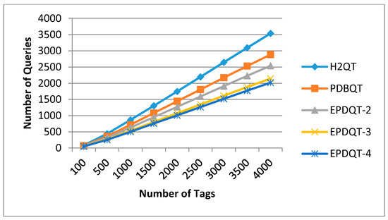
Figure 5.
Number of queries required to complete identification.
4.1.2. Number of Total Slots vs. Number of Tags
This experiment examines the effect that the number of tags has on the number of total slots generated by the reader to complete tag identification of the H2QT, PDBQT, EPDQT-2, EPDQT-3, and EPDQT-4 approaches. In this experiment, we ignore the tiny slots in the predetection phase and take only the number of slots that occurred in the tag response phase into account, since it will take more time to finish the process compared to the time spent in the predetection phase. The slot comparison results are given in Figure 6.
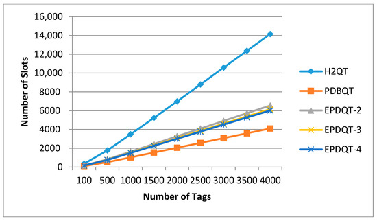
Figure 6.
Number of slots generated by each protocol.
In general, Figure 6 shows that H2QT has the most total slots. That is because H2QT allocates four slots to split tags in each query cycle. Many idle or collision slots will not be reduced. However, in our proposed EPDQT and PDBQT protocols, the reader uses a predetection mechanism to realize the distribution of tag IDs, which decreases most of the collision slots, and only a few collisions may occur in the tag response phase. As a result, the number of total slots decreases as well. For example, when t = 4000, the number of total slots generated by the reader in the H2QT, PDBQT, EPDQT-2, EPDQT-3, and EPDQT-4 protocols is 14,150, 4096, 6539, 6144, and 6017, respectively. Thus, our proposed EPDQT schemes perform 91.9% to 93.8% better than the H2QT scheme. Our proposed EPDQT protocols cost fewer slots than H2QT. However, the EPDQT protocols cost more slots than PDBQT. The main reason is that PDBQT uses a random number for each tag to respond during the predetection phase, and no slot will be allocated in the tag response phase once the collision is detected. On the other hand, the EPDQT protocols will allocate slots to split the collided tags. As a result, many collisions detected in the predetection phase will still collide in the tag response phase. We also note that the number of total slots in EPDQT-4 is 7.98% less than in EPDQT-2. This is because as the parameters in the EPDQT protocols increase, both queries and collisions decrease, which decreases the total slots needed to identify tags.
4.1.3. Delay Time vs. Number of Tags
This experiment examined the effect that the number of tags has on the total time required to complete tag identification of the H2QT, PDBQT, EPDQT-2, EPDQT-3, and EPDQT-4 approaches. The time comparison results are shown in Figure 7.
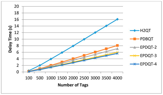
Figure 7.
Time required to complete tag identification.
In Figure 7, we can see that as the number of tags increases, the total time required for each algorithm to complete the identification increases. However, our proposed EPDQT schemes require less time compared to other schemes. For example, when t = 4000, the total time required in the H2QT, PDBQT, EPDQT-2, EPDQT-3, and EPDQT-4 protocols is 16.07, 8.07, 7.11, 6.01, and 5.65 s, respectively. Thus, our proposed EPDQT schemes perform 54.5% to 64.8% better than the H2QT scheme. This is because the EPDQT protocols can reduce the idle and collision slots substantially. We also note that the total time required in EPDQT-4 is 20.5% better than in PDQT-2. This indicates that for EPDQT schemes, the total time required decreases as the parameter value increases, since more time slots are allocated in the predetection phase and therefore more tags can be identified successfully.
4.1.4. System Efficiency vs. Number of Tags
In the following, we examine the effect that the number of tags has on system efficiency in terms of slots and time for the H2QT, PDBQT, EPDQT-2, EPDQT-3, and EPDQT-4 approaches. Results for slot system efficiency and time system efficiency are presented in Figure 8 and Figure 9. In terms of slot system efficiency, each of the compared approaches experiences similar system efficiency as the number of tags increases. For example, the slot system efficiency of the H2QT, PDBQT, EPDQT-2, EPDQT-3, and EPDQT-4 protocols is around 28.51%, 97.68%, 62.04%, 65.16%, and 66.58%, respectively, all of which are independent of the number of tags. The rationale behind these results is quite clear. Since the numbers of identification slots and total slots both increase as the number of tags increases, slot system efficiency almost flattens. Furthermore, slot system efficiency of the PDBQT, EPDQT-2, EPDQT-3, and EPDQT-4 protocols significantly outperforms the H2QT protocol. The rationale behind this result is also clear. In the H2QT protocol, each query cycle allocates four time slots for tags to respond. Some of the slots may receive one tag’s response and then identify the tag’s ID, but the rest of them may receive multiple tags’ responses or no response, and as a result the slot may collide or be idle. Therefore, the utilization of slots in H2QT is poor. On the other hand, in predetection-based protocols, no idle slot is allocated and most of the collisions are detected during the predetection phase. As a result, the allocated slots are almost used for identifying tags. However, the PDBQT protocol outperforms the EPDQT protocols, since it reduces most collision slots. Furthermore, for the EPDQT protocols, as the parameter increases, slot efficiency increases. Figure 8 shows that when t = 4000, the EPDQT-4 protocol performs around 5.3% better than the EPDQT-2 protocol.
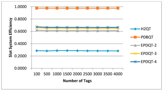
Figure 8.
Slot system efficiency of compared protocols.
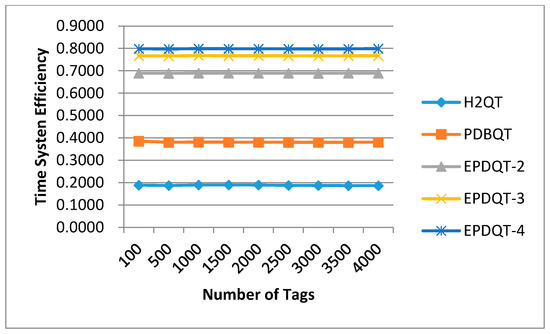
Figure 9.
Time system efficiency of compared protocols.
In terms of time system efficiency, as shown in Figure 9, each of the compared approaches experiences similar time system efficiency as the number of tags increases. For example, time system efficiency of the H2QT, PDBQT, EPDQT-2, EPDQT-3, and EPDQT-4 protocols is around 18.66%, 38.05%, 68.95%, 76.71%, and 79.85%, respectively, all of which are independent of the number of tags. The reason behind this result is similar to the reason for slot system efficiency. Furthermore, time system efficiency of the PDBQT, EPDQT-2, EPDQT-3, and EPDQT-4 protocols also significantly outperforms the H2QT protocol. The rationale behind this result is quite clear. Since there are many more queries in the H2QT protocol than in the predetection-based protocols, by adding the time for reader query commands and the waiting time from reader query to tag response, time system efficiency of H2QT is lower than other protocols. Furthermore, the proposed EPDQT protocols outperform the PDBQT scheme by around 30% to 41%. The rationale behind these results is quite clear. Since the communication overhead in the predetection phase of the proposed EPDQT protocols is much less than that in the PDBQT protocol, the time for each query cycle in EPDQT is much less than in PDBQT. As a result, the proposed EDPQT protocols can achieve better time system efficiency than the others.
4.2. Impact of the Number of Tags: Sequential Distribution
4.2.1. Number of Queries vs. Number of Tags
In this simulation, we compare the number of query cycles of the test protocols as the value of t increases from 100 to 4000 in sequential distribution fashion. The query cycle comparison results are given in Figure 10. In general, Figure 10 shows that each protocol generates fewer query cycles in sequential distribution than in uniform distribution. This is because the tag IDs are consecutive in sequential distribution. Thus, a sequence of tags may be evenly distributed into the query slots. As a result, more tags can be identified in a query cycle, which costs fewer query cycles than uniform distribution. Figure 10 also shows that H2QT has the most query cycles. The reason is quite clear. Despite the different distributions of tag IDs, H2QT spends more query cycles than the others, since it cannot reduce the collisions regardless of tag ID distribution. However, in our proposed EPDQT protocols, each query cycle can identify more tags than H2QT. The rationale behind this result is clear. Due to the predetection mechanism, the tiny slots are allocated sequentially. As a result, a sequence of tags can be identified in a query cycle, which decreases the number of query cycles dramatically. Furthermore, the EPDQT-4 protocol outperforms the EPDQT-2 and EPDQT-3 protocols. This is because the prefix string in EPDQT-4 is extended by five bits instead of the three bits and four bits in the EPDQT-2 and EPDQT-3 protocols, respectively, which costs fewer query cycles for EPDQT-4 to identify a tag’s ID.
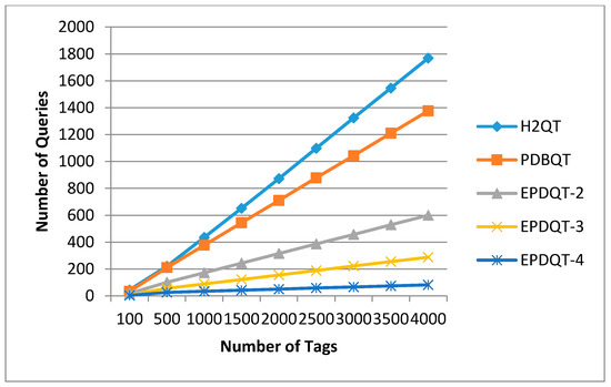
Figure 10.
Number of queries required to complete identification in sequential distribution.
4.2.2. Number of Total Slots vs. Number of Tags
In this simulation, we compare the number of total slots of test protocols. The slot comparison results are given in Figure 11. Figure 11 shows that each protocol generates fewer total slots in sequential distribution than uniform distribution due to the same reason given in the previous subsection. Figure 11 also shows that the EPDQT protocols significantly outperform H2QT, since there are much fewer query cycles in EPDQT than in H2QT. However, PDBQT performs a little better than EPDQT. This is because PDBQT generates much fewer collisions than EPDQT protocols, which costs fewer total slots.
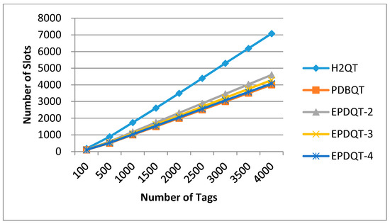
Figure 11.
Number of slots generated by each protocol in sequential distribution.
4.2.3. Delay Time vs. Number of Tags
This simulation compares the time needed to complete tag identification in sequential distribution for test protocols. The time comparison results are shown in Figure 12. Figure 12 shows that each protocol costs less time than uniform distribution. Figure 12 also shows that the EPDQT protocols significantly outperform the H2QT and PDBQT protocols.
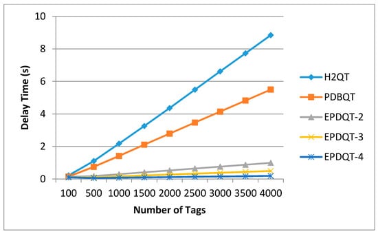
Figure 12.
Time required to complete tag identification in sequential distribution.
4.2.4. System Efficiency vs. Number of Tags
The comparison results for system efficiency in terms of slots and time for test protocols are given in Figure 13 and Figure 14. Each of the compared approaches experiences similar slot system efficiency as the number of tags increases, as shown in Figure 13. Figure 13 also shows that each protocol achieves better performance under sequential distribution than uniform distribution. This is because of the large amount of tag identifications in the query cycles of each protocol. Specifically, the EPDQT protocols achieve very high slot system efficiency (around 85.4% to 98.0%). This is because the EPDQT protocols generate much fewer collisions under sequential distribution than uniform distribution. However, time system efficiency of the EPDQT protocols is much worse than H2QT and PDBQT. The rationale behind this result is also clear. Since the EPDQT protocols cost a few collisions in sequential distribution, the time spent in tag identification is much less than the communication overhead for reader query commands. As a result, time system efficiency is low compared to H2QT and PDBQT protocols.
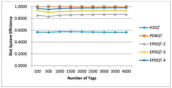
Figure 13.
Slot system efficiency of compared protocols in sequential distribution.
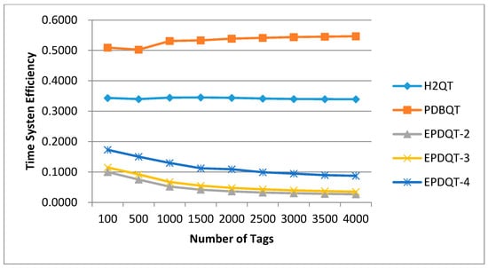
Figure 14.
Time system efficiency of compared protocols in sequential distribution.
5. Conclusions
Developing a highly efficient tag identification process in a large-scale RFID system is a crucial and very challenging task. Many collisions may occur during the tag identification process due to the nature of large-scale RFID systems. On the other hand, many idle cycles may also occur, since tag IDs in, say, a big shopping mall may have some common prefix (e.g., common product code or vendor ID). Identification protocols such as H2QT can reduce idle cycles, but there are still many collisions. Therefore, collision resolution becomes a major issue in improving performance. In this paper, we proposed a nearly collision-free tag identification algorithm to reduce collisions and improve identification performance substantially. We used the predetection technique to detect all idle cycles and many possible collided inquiries. As a result, we were able to not only reduce unnecessary collided inquiries, but also eliminate idle time slots. Therefore, the performance of tag identification can be significantly improved. To evaluate the efficiency of our proposed protocol, we implemented our proposed EPDQT protocol along with previous H2QT and PDBQT protocols in two tag ID distributions: uniform distribution and sequential distribution. The simulation results show that our proposed protocol can provide considerable improvement in terms of number of queries, number of total slots, system efficiency, and total time required for tag identification. Simulation results also show that the proposed EPDQT protocol can provide substantial improvement in identification time for a large-scale RFID system.
Author Contributions
Yu-Hsiung Lin and Chiu-Kuo Liang conceived and designed the experiments; Yu-Hsiung Lin performed the experiments; Yu-Hsiung Lin and Chiu-Kuo Liang analyzed the data; Yu-Hsiung Lin contributed reagents/materials/analysis tools; Chiu-Kuo Liang wrote the paper.
Conflicts of Interest
The authors declare no conflict of interest.
References
- Vogt, H. Efficient Object Identification with Passive RFID Tags. Lect. Notes Comput. Sci. 2002, 2414, 98–113. [Google Scholar]
- Li, Y.; Ding, X. Protecting RFID communications in supply chains. In Proceedings of the 2nd ACM Symposium on Information, Computer and Communications Security, Singapore, 20–22 March 2007; ACM: New York, NY, USA, 2007; pp. 234–241. [Google Scholar]
- Shirehjini, A.; Yassine, A.; Shirmohammadi, S. Equipment location in hospitals using RFID-based positioning system. IEEE Trans. Inf. Technol. Biomed. 2012, 16, 1058–1069. [Google Scholar] [CrossRef] [PubMed]
- Lee, S.R.; Joo, S.D.; Lee, C.W. An enhanced dynamic framed slotted ALOHA algorithm for RFID tag identification. In Proceedings of the Second Annual International Conference on Mobile and Ubiquitous Systems: Networking and Services, San Diego, CA, USA, 17–21 July 2005; pp. 166–172. [Google Scholar]
- Dardari, D.; Decarli, N.; Guerra, A.; Guidi, F. The future of ultra-wideband localization in RFID. In Proceedings of the 2016 IEEE International Conference on RFID (RFID), Orlando, FL, USA, 3–5 May 2016. [Google Scholar]
- Qiu, L.; Huang, Z.; Wirström, N.; Voigt, T. 3DinSAR: Object 3D localization for indoor RFID applications. In Proceedings of the 2016 IEEE International Conference on RFID (RFID), Orlando, FL, USA, 3–5 May 2016. [Google Scholar]
- Naderiparizi, S.; Parks, A.N.; Kapetanovic, Z.; Ransford, B.; Smith, J.R. WISPCam: A battery-free RFID camera. In Proceedings of the 2015 IEEE International Conference on RFID (RFID), San Diego, CA, USA, 15–17 April 2015; pp. 166–173. [Google Scholar]
- Philipose, M.; Smith, J.R.; Jiang, B.; Mamishev, A.; Roy, S.; Sundara-Rajan, K. Battery-free wireless identification and sensing. IEEE Pervasive Comput. 2005, 4, 37–45. [Google Scholar] [CrossRef]
- Park, J.; Chung, M.; Lee, T.J. Identification of RFID Tags in Framed-Slotted ALOHA with Robust Estimation and Binary Selection. IEEE Commun. Lett. 2007, 11, 452–454. [Google Scholar] [CrossRef]
- Klair, D.K.; Chin, K.W.; Raad, R. An investigation into the energy efficiency of pure and slotted aloha based RFID anticollision protocols. In Proceedings of the IEEE International Symposium on a World of Wireless, Mobile and Multimedia Networks (WoWMoM), Espoo, Finland, 18–21 June 2007; pp. 1–4. [Google Scholar]
- Zhen, B.; Kobayashi, M.; Shimizui, M. Framed aloha for multiple RFID objects Identification. IEICE Trans. Commun. 2005, E88-B, 991–999. [Google Scholar] [CrossRef]
- Law, C.; Lee, K.; Siu, K.Y. Efficient Memoryless Protocol for Tag Identification. In Proceedings of the 4th International Workshop on Discrete Algorithms and Methods for Mobile Computing and Communications, Boston, MA, USA, 11 August 2000. [Google Scholar]
- Myung, J.; Lee, W. An adaptive memoryless tag anticollision protocol for RFID networks. In Proceedings of the 24th Annual IEEE Conference on Computer Communications (INFOCOM’05), Poster Session, Miami, FL, USA, 13–15 March 2005. [Google Scholar]
- Choi, H.S.; Cha, J.R.; Kim, J.H. Improved Bit-by-bit Binary Tree Algorithm in Ubiquitous ID System. In Proceedings of the 5th Pacific Rim Conference on Multimedia, Tokyo, Japan, 30 November–3 December 2004; pp. 696–703. [Google Scholar]
- Myung, J.; Lee, W.; Srivastava, J. Adaptive binary splitting for efficient RFID tag anti-collision. IEEE Commun. Lett. 2006, 10, 144–146. [Google Scholar] [CrossRef]
- Capetanakis, J.I. Tree algorithms for packet broadcast channels. IEEE Trans. Inf. Theory 1979, 25, 505–515. [Google Scholar] [CrossRef]
- Feng, B.; Tao, L.J.; Bo, G.J.; Hua, D.Z. ID-Binary tree stack anti-collision algorithm for RFID. In Proceedings of the 11th IEEE Symposium on Computers and Communications (ISCC’06), Cagliari, Italy, 26–29 June 2006; pp. 207–212. [Google Scholar]
- Sahoo, A.; Iyer, S.; Bhandari, N. Improving RFID System to Read Tags Efficiently; KRSIT Technical Report; IIT Bombay: Mumbai, India, June 2006. [Google Scholar]
- Zhou, Z.; Gupta, H.; Das, S.R.; Zhu, X. Slotted Scheduled Tag Access in Multi-Reader RFID Systems. In Proceedings of the IEEE International Conference on Networks Protocols (ICNP), Beijing, China, 16–19 October 2007; pp. 61–70. [Google Scholar]
- Ryu, J.; Lee, H.; Seok, Y.; Kwon, T.; Choi, Y. A Hybrid Query Tree Protocol for Tag Collision Arbitration in RFID systems. In Proceedings of the IEEE International Conference on Communications (ICC-07), Glasgow, UK, 24–28 June 2007; pp. 5981–5986. [Google Scholar]
- Kim, T.H.; Lee, S.J. A Hybrid Hyper Tag Anti-Collision Algorithm in RFID System. In Proceedings of the 11th International Conference on Advanced Communication Technology (ICACT 2009), Phoenix Park, Korea, 15–18 February 2009; Volume 2, pp. 1276–1281. [Google Scholar]
- Liang, C.K.; Chien, Y.C.; Tsai, C.H. A Pre-Detection Query Tree Tag Anti-Collision Scheme in RFID Systems. In Proceedings of the Seventh International Conference on Sensor Technologies and Applications (SENSORCOMM’13), Barcelona, Spain, 26–29 August 2013; pp. 51–56. [Google Scholar]
- Zhou, F.; Jin, D.; Huang, C.; Hao, M. Optimize the Power Consumption of Passive Electronic Tags for Anti-collision Schemes. In Proceedings of the 5th International Conference on ASIC, Beijing, China, 21–24 October 2003; Volume 2, pp. 1213–1217. [Google Scholar]
- Jia, X.; Feng, Q.; Yu, L. Stability analysis of an efficient anti-collision protocol for RFID tag identification. IEEE Trans. Commun. 2012, 60, 2285–2294. [Google Scholar] [CrossRef]
- Lai, Y.C.; Hsiao, L.Y.; Lin, B.S. Optimal slot assignment for binary tracking tree protocol in RFID tag identification. IEEE/ACM Trans. Netw. 2015, 23, 255–268. [Google Scholar] [CrossRef]
- Yan, Y.N.; Xiong, J. An Efficient Tag Identification Algorithm Based on Improved Collision Detection. IEICE Trans. Commun. 2016, E99-B, 465–470. [Google Scholar]
- Landaluce, H.; Perallos, A.; Onieva, E.; Arjona, L.; Bengtsson, L. An Energy and Identificaion Time Decreasing Procedure for Memoryless RFID Tag Anticollision Protocols. IEEE Trans. Wirel. Commun. 2016, 15, 4234–4247. [Google Scholar] [CrossRef]
- EPCglobal. EPC Radio-Frequency Identity Protocols Generation-2 UHF RFID. November 2013. Available online: http://www.gs1.org/sites/default/files/docs/epc/uhfc1g2_2_0_0_standard_20131101.pdf (accessed on 12 December 2017).
© 2018 by the authors. Licensee MDPI, Basel, Switzerland. This article is an open access article distributed under the terms and conditions of the Creative Commons Attribution (CC BY) license (http://creativecommons.org/licenses/by/4.0/).