Article

An Improved Chosen Plaintext Attack on JPEG Encryption

1
School of Computer Science and Engineering, South China University of Technology, Guangzhou 510006, China
2
School of Electronics and Information Technology, Sun Yat-sen University, Guangzhou 510275, China
3
Guangdong Provincial Key Laboratory of Big Data Computing, The Chinese University of Hong Kong, Shenzhen 518172, China
*
Author to whom correspondence should be addressed.
J. Sens. Actuator Netw. 2025, 14(4), 72; https://doi.org/10.3390/jsan14040072 (registering DOI)
Submission received: 31 May 2025 / Revised: 6 July 2025 / Accepted: 10 July 2025 / Published: 14 July 2025

Abstract

Format-compatible encryption can be used to ensure the security and privacy of JPEG images. Recently, a JPEG image encryption method proved to be secure against known plaintext attacks by employing an adaptive encryption key, which depends on the histogram of the number of non-zero alternating current coefficients (ACC) in Discrete Cosine Transform (DCT) blocks. However, this scheme has been demonstrated to be vulnerable to chosen-plaintext attacks (CPA) based on the run consistency of MCUs (RCM) between the original image and the encrypted image. In this paper, an improved CPA scheme is proposed. The method of incrementing run-length values instead of permutation is utilized to satisfy the uniqueness of run sequences of different minimum coded units (MCUs). The experimental results show that the proposed method can successfully recover the outlines of plaintext images from the encrypted images, even with lower-quality factors.

1. Introduction

With the rapid development of the Internet and multimedia technologies, images have become one of the most common media for information dissemination due to their intuitiveness. However, digital images often raise significant privacy and confidentiality concerns, as they frequently contain sensitive personal or confidential data—exemplified by applications like tele-medicine, cloud storage, and online identity verification. Consequently, ensuring image security and confidentiality during storage and transmission has emerged as a critical challenge in information security.
Among digital image formats, JPEG dominates due to its high compression ratio and acceptable perceptual quality at reduced file sizes; most online images are JPEG-encoded. While a variety of generic encryption techniques exist for images, the simplest approach treats the JPEG image as a bit-stream and directly applies conventional ciphers like Data Encryption Standard (DES) [1] or Advanced Encryption Standard (AES) [2]. However, this method destroys the image’s native file structure and format, rendering the encrypted output incompatible with the original image format. Therefore, recent years have seen a surge in research focused on format-compatible JPEG image encryption.
Joint compression–encryption designs, such as those in [3,4,5], embed encryption within the rate–distortion optimization loop to ensure the ciphertext remains size-preserving. Selective-encryption strategies, pioneered by [6,7], have since evolved and been applied to domain-specific data, such as medical images [8] and e-comics [9]. Chaos-based schemes remain popular due to their strong diffusion properties; examples range from the efficient approach in [10] to the chaotic S-box design of [11] and the block-adaptive method in [12]. Format-compliant scrambling of the quantized DCT coefficients was explored in [13], while bit-stream level protection achieving file size preservation was demonstrated in [14]. More recent work incorporates techniques such as secret sharing [15] and advanced entropy-coding manipulation [16]. Comprehensive overviews of these research directions are provided in surveys [17,18]. A notable JPEG encryption algorithm proposed by He et al. [19] incorporates several techniques: permutation of quantized direct current coefficient (DCC) differences grouped by sign, swapping of left and right halves within variable-length DC difference groups, random shuffling of non-zero ACC categorized by run-length, and scrambling of DCT blocks excluding DCC. This approach reduces key management overhead, avoids file size expansion, and demonstrates strong robustness against many common cryptanalytic attacks.
However, one inherent challenge in designing JPEG-compatible encryption schemes is addressing the intrinsic characteristics of JPEG encoding that may introduce vulnerabilities. For example, many JPEG encryption approaches preserve intra-block pixel correlation to ensure format compatibility and compression efficiency. This preservation, while beneficial for maintaining JPEG structure, has been shown to facilitate certain cryptanalytic attacks, as it allows adversaries to exploit statistical dependencies within pixel blocks. Recent studies, such as the work by Cardona-López et al. [20], highlight how transformations like the Negative–Positive Transformation (NPT) maintain pixel block correlation, which may compromise encryption strength if not complemented by additional security mechanisms.
In parallel with the development of stronger algorithms, the cryptanalysis of JPEG encryption has advanced rapidly. Universal attacks, which operate independently of the underlying cipher, have been proposed for permutation–substitution structures [21]. Adaptive-key mechanisms have proven particularly fragile: [22,23] developed effective CPA schemes by exploiting run-length information or invariant characteristics leaked through ACC. Beyond still images, insights drawn from multimedia security—such as the cryptanalysis of start-code and DCT-domain permutations in video streams [24,25]—further highlight potential vulnerabilities in analogous JPEG encryption schemes. Beyond static images, drawing on research from multimedia security—such as the cryptanalysis of start-codes or DCT-domain permutations in video streams [24,25]—further reveals potential vulnerabilities in JPEG encryption schemes. Although they exhibit favorable statistical characteristics, chaos-based ciphers have been proven to be insecure under rigorous cryptanalytic analysis [26,27,28]. To objectively quantify security risks, researchers have proposed dedicated security metrics, such as the perceptual-security index [29], local-entropy evaluation [30], and jigsaw-solver robustness tests [31]. Oezkaynak et al. [32] offer a concise, critical assessment of these collective findings.
Although the adaptive-key encryption algorithm proposed by He et al. [19] has been shown to be vulnerable to chosen plaintext attacks [22,23], its success rate degrades with low JPEG quality factors. To address this, we substitute run-length sequence permutation with run-length incrementation—thereby ensuring unique run sequences across all MCUs—which both increases the attack’s success probability and enhances its efficiency.
The remainder of this paper is organized as follows. Section 2 reviews the fundamentals of CPA against JPEG encryption algorithms. Section 3 details the proposed improvements to the attack methodology. Section 4 reports experimental results that compare baseline and improved CPA performance. Finally, Section 5 summarizes our findings and outlines future directions for strengthening the security of JPEG encryption schemes.

2. Current CPA Scheme

2.1. ACC Encryption in He et al.’s JPEG Encryption Algorithm

The CPA scheme proposed in [22] exploits vulnerabilities in the ACC encryption process of He et al.’s JPEG encryption algorithm. In JPEG images, the DCC only determines the average brightness of all pixels within an MCU, while the ACC governs the image details of the MCU [33]. This fundamental property implies that image content can be substantially reconstructed by recovering the ACCs while setting all DCCs to “00”. To establish the foundation for our discussion, we first analyze the ACC encryption mechanism in He et al.’s algorithm.
The ACC encryption process in He et al.’s algorithm consists of three sequential steps: (1) adaptive key generation, (2) permutation of ACCs with identical run values, and (3) inter-MCU permutation. These steps are elaborated below.
(1) Adaptive Key Generation: This process introduces the concept of the MCU histogram. For a given image O, let O i represent the i-th MCU of the image, and p i denote the count of non-zero ACCs in the i-th MCU. We define h w as the number of MCUs containing exactly w non-zero ACCs in the image:
h w = # O i p i = w , 1 i n
where # denotes the cardinality of a set.
The MCU histogram H O of image O is then defined as
H O = h w 0 w 63
Both the initial key k e y u s e r and MCU histogram H O participate in generating the adaptive key k e y A . Based on H O , a 512-bit hash code κ is generated using a hash function:
κ = F u n c S H A 3 512 ( H O )
The adaptive key k e y A is subsequently produced by combining the hash code κ with the user key k e y u s e r . The detailed procedure can be found in [19].
(2) Permutation of ACCs with Identical Run Values: The term run refers to an attribute obtained during the entropy-coding process of JPEG encoding for each non-zero ACC. It represents the number of zero-valued ACCs between the current non-zero ACC and the previous non-zero ACC [33]. The permutation of ACCs with identical run values maintains a constant file size. The set of ACCs with a run size of k ( 0 k 63 ) can be expressed as
S k = { a i , j | r i , j = k , 1 i n , 1 k p i }
For each set S k , the secret key k e y A is used to generate a random permutation sequence Π k :
Π k = { Π k ( t ) | 1 t # { S k } }
For example, if there are 500 ACCs with a run value of 1, the algorithm generates a permutation sequence Π 1 with a length of 500 based on k e y A . The system then sequentially scans all ACCs starting from the 0-th MCU, identifies these 500 ACCs, flattens them into a one-dimensional array, and applies Π 1 to permute them. After permutation, the set of ACCs with identical run values becomes
S k ( t ) = S k ( Π k ( t ) )
Consequently, the original image O is transformed into O .
(3) Inter-MCU Permutation: The final encryption stage permutates the MCU without DCC to preserve the file size. The secret key k e y A generates a random permutation sequence Ψ :
Ψ = { Ψ ( i ) | 1 i n }
Applying Ψ to the intermediate image O yields the final ciphertext image E. The MCU set of E becomes
E i = O Ψ ( i )
Figure 1 demonstrates the complete encryption process for a plaintext image O containing three MCUs, using Ψ = { 3 , 1 , 2 } , Π 0 = { 5 , 2 , 4 , 1 , 3 } , Π 1 = { 2 , 4 , 3 , 1 } . The original 63 ACC values within each MCU are transformed into a run–value sequence composed of run–value pairs. Each run–value pair corresponds to a non-zero ACC, with the run and value components represented by separate rectangles. Among all ACCs, those with a run value of 0 are highlighted in red, while those with a run value of 1 are highlighted in blue. To transform image O into O , it is necessary to apply permutation sequences Π 0 and Π 1 to five ACCs with run = 0 and four ACCs with run = 1, respectively. Furthermore, to transform image O into image E, the permutation sequence Ψ must be applied to three MCUs. EOB markers following each MCU are omitted in the figure.

2.2. Security Vulnerabilities in He et al.’s ACC Encryption

The following section explains two security risks in He et al.’s ACC encryption: (1) RCM between plaintext and ciphertext, and (2) the immutability of the MCU histogram. By combining these two risks, the CPA scheme in [22] can be implemented to recover all ACCs of the ciphertext image.
(1) RCM between plaintext and ciphertext: First, we introduce the concepts of Run sequence and RCM. For an MCU O i , let its j-th ACC be a i , j and the run of its j-th ACC be r i , j ; then, its run sequence R i is
R i = { r i , j 1 j p i }
Among all MCUs in an image, there may exist two or more MCUs with identical run sequences. This phenomenon is called run consistency among MCUs, abbreviated as RCM.
Here, we specifically refer to the RCM phenomenon existing between plaintext and ciphertext images. The ACC encryption process in [19] involves two permutation steps: permutation among ACCs with identical runs, and permutation among MCUs. The first step only permutes other numerical values of ACCs with the same run, without modifying the run sequences in any MCU. The second step permutes all MCUs (excluding DCC) as whole units, which also does not change the run sequence within each MCU. Therefore, the Ψ i -th MCU in ciphertext image E and the i-th MCU in plaintext image O exhibit RCM.
The occurrence of RCM facilitates the reverse derivation of the inter-MCU permutation sequence Ψ , because these identical run sequences can serve as crucial clues for tracking the positional changes of MCUs before and after permutation. This is particularly critical for implementing the chosen plaintext attack.
(2) Immutability of MCU Histogram: The MCU histogram is defined as follows: the number of MCUs containing a specific count of non-zero ACCs for each possible count of non-zero ACCs. We now analyze the two steps in the ACC encryption process outlined in [19]—the permutation of ACCs with identical run values and permutation among MCUs. The first step exclusively permutes non-zero ACCs without converting zero ACCs to non-zero values or vice versa within any MCU. The second step permutes entire MCUs as atomic units, thereby preserving the count of MCUs corresponding to each specific non-zero ACC quantity. Consequently, the ciphertext image E maintains an identical MCU histogram to the plaintext image O.
The immutability of the MCU histogram is crucial for the execution of this JPEG encryption algorithm because it allows users to directly extract the same MCU histogram from ciphertext as from plaintext. By combining this with the user key, the complete key can be recovered, thereby reducing the key management overhead. However, this characteristic can be exploited to construct CPA-specific plaintext images that preserve key consistency with the original plaintext, thereby enabling the proposal of CPA schemes.
In the CPA scenario, the attacker possesses a “black box” capable of encrypting plaintext images into ciphertext images. The attacker’s objective is to extract information from multiple plaintext–ciphertext pairs (a set consisting of a plaintext image and its corresponding ciphertext image), thereby obtaining encryption-related information without knowledge of the secret key.

2.3. The Five Steps of the Current CPA Scheme

For the CPA scheme proposed in [22], the construction of plaintext images is crucial. This construction involves two key steps. First is eliminating the RCM phenomenon within the image using the single-permutation method to facilitate the prediction of the MCU permutation sequence Ψ . Second is assigning values to ACCs to facilitate the prediction of Π . After successfully constructing the plaintext images, the attacker must infer both the MCU permutation sequence Ψ and the ACC permutation sequence Π (for ACCs with identical run values) using information derived from the plaintext–ciphertext pairs. Ultimately, this enables the reconstruction of image details from the target plaintext image. The following sections will sequentially explain each of these steps in detail.
(1) Plaintext Image Construction—Eliminating RCM via Single Permutation: The initial step involves eliminating internal RCM phenomena in the ciphertext image to enhance the prediction accuracy of the MCU permutation sequence Ψ . As previously established, identical run sequences between ciphertext and plaintext images serve as crucial markers for tracking MCU positional changes during permutation. Consider a concrete example: when an MCU possesses a unique run sequence R 1 within the image (where pre-permutation index = i 1 , post-permutation index = j 1 ), we can determine that in the MCU permutation sequence Ψ , the MCU originally at position i 1 has been permuted to position j 1 . However, if two MCUs share identical run sequences R 1 (with pre-permutation indices i 1 , i 2 and post-permutation indices j 1 , j 2 ), the sequence R 1 alone cannot determine whether i 1 has been permuted to j 1 or j 2 , since their run sequences are identical. It can be seen that the existence of the RCM phenomenon in the image will seriously affect the prediction of the MCU permutation sequence Ψ . A method must be proposed to eliminate the RCM phenomenon in the image as much as possible.
The current CPA scheme employs a “single permutation” to resolve RCM. For instance, when R 1 = { 0 , 0 , 1 , 2 , 0 } appears in both MCU- i 1 and MCU- i 2 , we modify one MCU’s run sequence (e.g., transforming MCU- i 1 ’s sequence to R 1 = { 1 , 0 , 0 , 2 , 0 } ), thereby eliminating their RCM relationship. This process maintains constant non-zero ACC counts (5 in this case), preserving the MCU histogram and ensuring consistent key recovery. The methodology extends analogously to cases involving three or more duplicate MCUs, with detailed rules specified in [22].
(2) Plaintext Image Construction—Assigning Values to ACCs: In predicting Ψ , we leverage identical run sequences between plaintext and ciphertext images as clues to track the positional changes of MCUs before and after permutation. Similarly, for predicting Π , we require a method to track the positional changes of ACCs with identical run values. When the number of ACCs sharing the same run value in an image is relatively small, we can assign distinct values to each such ACC to enable Π prediction. For most images, the number of ACCs with run = 0 far exceeds those with other run values. Thus, by satisfying the “demand” for run = 0 ACCs, we can construct the entire image in a Π -predictable form.
According to [22], for Quality Factor (QF) = 100, the ACC of JPEG images takes the value range of [ 924 , 924 ] . If there are 1000 run = 0 ACCs with a value range of [ 924 , 924 ] , we can assign each of them a unique value in the range of [ 500 , 1 ] [ 1 , 500 ] (note: 0 is excluded since we focus on non-zero ACCs). With correct Ψ prediction, each unique ACC value serves as a clue to accurately infer Π . Thus, only one plaintext image is needed for complete Π prediction.
If the number of run = 0 ACCs exceeds the non-zero value range size γ , a single plaintext image becomes insufficient, as it can provide only γ distinct tracking clues. However, by using two plaintext images (A and B) with identical run sequences across all MCUs, we can combine the values of co-located ACCs in A and B to form composite clues. This is equivalent to taking the Cartesian product of the non-zero ACC value range with itself, now offering γ 2 distinct combinations. Similarly, if we use three images (A, B, and C), we can provide γ 3 distinct value combinations. Figure 2 demonstrates the constructed non-zero ACC of Image A and B for Π prediction. ACC instances with run = 0 are marked in red, whereas those with run = 1 are marked in blue. For run = 0 ACCs, the composite clues (A and B value pairs) are { 2 , 2 } , { 2 , 1 } , { 2 , 1 } , { 2 , 2 } , { 1 , 2 } , etc. For other run values (e.g., run = 1), the pairs are { 2 , 2 } , { 2 , 1 } , { 2 , 1 } , { 2 , 2 } , etc. Critically, all composite clues remain distinct, enabling unambiguous Π inference. Detailed assignment methods are described in [23].
To ensure accurate prediction of the permutation sequence Π , a sufficient number of plaintext–ciphertext pairs x is required. According to [22], let # S 0 denote the count of ACCs with run = 0 in an image, and γ represent the size of the non-zero value range for ACC (e.g., for ACC in [ 924 , 924 ] , γ = 1848). The required number of plaintext–ciphertext pairs x for executing the CPA scheme on this image is given by
x = log γ # S 0
(3) Prediction of MCU Permutation Sequence Ψ : The prediction of the MCU permutation sequence Ψ requires only one plaintext–ciphertext pair. Here, we use a plaintext image generated by the incremental value method and obtain its corresponding ciphertext image through the black box of the JPEG encryption algorithm. To predict the MCU permutation sequence Ψ , we simply need to identify the correspondence between identical run sequences in each ciphertext–plaintext image pair, from which the entire permutation sequence can be deduced. However, if RCM phenomena still exist, the prediction of Ψ may become inaccurate.
(4) Prediction of ACC Permutation Sequence Π for Identical Run Values: The prediction of ACC permutation sequence Π requires x plaintext–ciphertext pairs. For a 512 × 512 image, x = 2, meaning two plaintext–ciphertext pairs are needed. As mentioned earlier, when constructing two plaintext images A and B, we ensure that the “combined values of ACCs at the same position in A and B” are unique for all ACCs with the same run value. Therefore, we can use these combined ACC value pairs as clues to track the positional changes of each ACC before and after permutation. If Ψ is predicted correctly, the Π predicted through this method is guaranteed to be completely accurate because the uniqueness of tracking clues is ensured.
However, if there are errors in Ψ prediction, the impact on Π prediction would be significant. The JPEG encryption algorithm described in [19] implements two sequential permutation stages: first executing permutation sequence Π for each run value by sequentially traversing from MCU-0 and numbering each ACC as 0, 1, 2 through # S k , transforming plaintext image O into intermediate image O , then performing the permutation sequence Ψ that rearranges MCUs while simultaneously causing secondary scrambling of internal ACCs, ultimately generating the final ciphertext image E. Consequently, accurate Π prediction necessitates first correctly predicting Ψ , then applying Ψ ’s inverse operation to ciphertext image E to recover intermediate state O before finally predicting Π from O . Incorrect Ψ prediction prevents proper reversal of the secondary ACC scrambling induced by Ψ , potentially introducing compounded errors in Π prediction, with [22] providing a comprehensive analysis of these error-propagation mechanisms and their detrimental effects.
(5) Recovery of Target Ciphertext Image: After successfully predicting the permutation sequences Ψ and Π , we can recover the target ciphertext image by sequentially applying the inverse operations of Ψ and Π . Finally, by setting all DCCs of the MCUs to “0”, we successfully restore the image details of the target ciphertext image.

2.4. The Overall Process of the Current CPA Scheme

When the test image size is 512 × 512, the calculation of x reaches its maximum value of 2 according to [22]. The overall process of the current CPA scheme when x = 2 is shown in Figure 3. The dashed red box represents the permutation of Ψ , while the dashed blue box represents the permutation of Π . In the original CPA scheme, two plaintext images, Image A and Image B, were constructed (with Image C being an “intermediate product”). To predict the permutation sequence Ψ , one of the images, either Image A or Image B, is required. To predict the permutation sequence Π , both Image A and Image B are necessary.

2.5. Current Limitations of the Single Permutation Method

The accuracy of the current CPA scheme primarily depends on the number of MCUs exhibiting RCM in the constructed plaintext images. As the number of MCUs in the plaintext image increases, the error rate in the recovered image also rises. The existing approach employs the “single permutation method” to reduce RCM during plaintext image construction. While this method can partially mitigate RCM, it suffers from two critical issues:
(1) Insufficient Permutation Variability for High-RCM Cases: If the number of MCUs involved in RCM exceeds all possible single-permutation variations, RCM cannot be fully eliminated. There exist certain run sequences for which the number of unique single permutation possibilities is extremely limited. For example, for run sequences that are all zeros, such as { 0 } , { 0 , 0 , 0 } , the single-permutation method cannot be performed because all permutations result in the same sequence. For shorter run sequences, such as { 0 , 1 } and { 0 , 0 , 1 } , the permutation variability is inherently low due to the limited number of unique arrangements.
If a large number of MCUs share these run sequences, it becomes increasingly likely that the number of MCUs belonging to the RCM will surpass the total number of permutation possibilities. In such cases, the single-permutation method fails to fully resolve RCM, as the number of MCUs associated with the RCM exceeds the set of all possible unique variations that can result from reordering the sequence.
(2) Unintentional Introduction of New RCM: Even when applying single permutations, the resulting run sequences may coincidentally remain non-unique in the image. For instance, suppose an MCU with R 1 = { 0 , 0 , 1 , 2 , 0 } is permuted to R 1 = { 1 , 0 , 0 , 2 , 0 } , but another MCU already has the same R 1 sequence. This means that while resolving one RCM instance, the method may inadvertently introduce new RCM cases.
These two problems lead to persistent RCM phenomena in the constructed plaintext images, ultimately reducing the success rate of the current CPA scheme.

3. Improved CPA Scheme

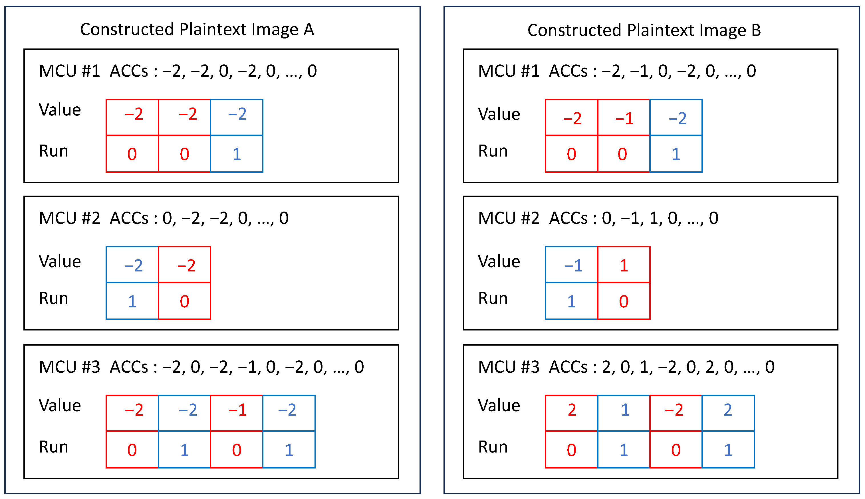
3.1. Plaintext Image Generation Using the Additive Value Method

To address the aforementioned two issues, we proposed an enhanced approach for eliminating RCM, termed the “Additive Value Method”, as its core operation involves adding a specific value to a run component within an ACC in an MCU. This method effectively mitigates RCM phenomena in the constructed plaintext images, thereby improving the overall success rate of the CPA scheme. The detailed procedure is as follows:
Variable Declaration: For a repeated run sequence R, let l denote its element count, and v represent the sum of all element values. Define y = 63 l v . Denote z as the number of MCUs containing run sequence R.
Case 1: If z 1 l , select z-1 MCUs from those exhibiting RCM, indexed as i ( 0 i z 2 ). For the i-th MCU, add y to the i-th value in its run sequence. Verify whether the modified run sequence has previously appeared in the image. If duplication is detected, decrease the added value by 1 and revalidate. If unique, implement this modification.
Case 2: If l < z 1 y l , similarly select z 1 MCUs with indices i ( 0 i z 2 ) . For MCUs satisfying 0 i l 1 , add y to the i-th run value; for l i 2 l 1, add ( y 1 ); for 2 l i 3 l 1 , add ( y 2 ). This pattern continues until all z 1 MCUs are processed. Throughout this process, each modification requires verification of run sequence uniqueness, with value decrementation and rechecking upon duplication detection.
Case 3: If z 1 > y l , the method can process y l MCUs following Case 2’s approach, while the remaining MCUs cannot be modified, thus preserving residual RCM phenomena.
The core concept of this method is to ensure that non-zero ACCs appear as late as possible within an MCU. The implemented approach randomly selects an ACC and adds a maximally permissible value y to its run value. Each MCU contains 63 ACCs. In the run sequence, each element represents a non-zero ACC, while each run value indicates the count of consecutive zero-valued ACCs. Consequently, the total number of ACCs preceding the current "EOB" marker equals l + v . To prevent exceeding the ACC count boundary, the maximum allowable value for y is set as 63 l v .
To better demonstrate how the additive value method works, a few examples are given below. Assume there are z MCUs sharing the run sequence { 0 , 1 , 0 , 0 , 1 } , and they are named MCU #1, MCU #2, …, MCU #z. It can be calculated that l = 5 , v = 2 , y = 56 .
When z = 6 , since z 1 l , this case belongs to Case 1; when z = 8 , since l < z 1 y l , this case belongs to Case 2; when z = 282 , since z 1 > y l , this case belongs to Case 3. Figure 4a–c illustrates the run sequencesof MCU #1, MCU #2, …, MCU #z after the execution of the additive value method when z = 6 , z = 8 , and z = 282 , respectively. In Figure 4, it is assumed that all run sequences generated during the process are unique across the entire image.
Figure 5 illustrates the run sequences of eight MCUs after the execution of the additive value method under the same conditions as Figure 4b when z = 8 . However, it is assumed that the run sequence { 56 , 1 , 0 , 0 , 1 } has already been generated in a previous execution of the additive value method aimed at eliminating the duplicate run sequence { 1 , 1 , 0 , 0 , 1 } . In this case, the run sequence of MCU #2 should be { 55 , 1 , 0 , 0 , 1 } . Correspondingly, the run sequence of MCU #7 should be { 54 , 1 , 0 , 0 , 1 } .
The following analysis examines how the additive value method addresses the two limitations inherent in the single-permutation approach.
Regarding the first issue, the new method yields y l possible outcomes, which significantly exceeds the permutation possibilities of the original method when l is small. Taking { 0 } as an example, the current approach provides y l = 62 × 1 = 62 possible variations, a substantial improvement over the original method’s zero possible permutations. Since low-QF images typically contain numerous run sequences with small l values, this method demonstrates superior effectiveness for such compressed images.
For the second issue, the new RCM elimination method ensures that the generated run sequences are almost certainly unique among all MCUs in the original image. In JPEG encoding, the quantization table typically contains smaller values in the top-left corner and larger values in the bottom-right corner. Due to the human eye’s varying sensitivity to low-frequency and high-frequency information, we need to discard more high-frequency information concentrated in the bottom-right corner. This results in quantized MCUs having more non-zero values in the top-left region, while the bottom-right region is mostly filled with zeros. Consequently, the ZigZag scan order can quickly traverse all non-zero values before using the EOB marker to skip the remaining zero-valued ACC. Conversely, the probability of quantized MCUs still containing non-zero ACC in the bottom-right region is extremely low, as most images do not exhibit extremely high-frequency components within a single MCU. This explains why the added value y needs to be as large as possible. For any duplicate run sequences that may occur during the additive value process, the mechanism in Figure 5 can eliminate such duplication.

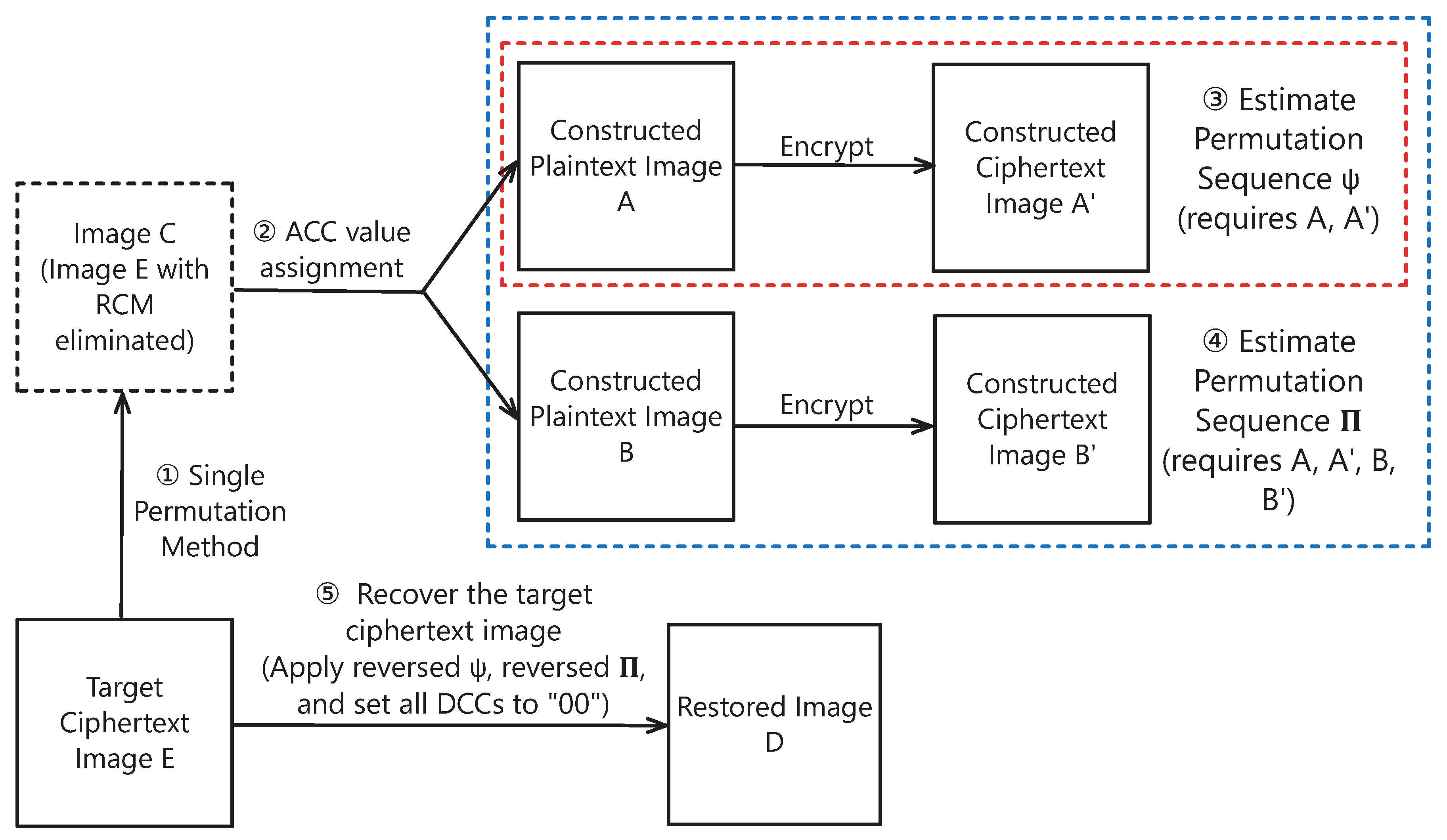
3.2. The Overall Process of the Improved CPA Scheme

Compared to the single-permutation method, the additive value method can more effectively eliminate RCM phenomena. However, implementing the additive value method requires generating one additional plaintext image when performing a complete CPA. In the original single-permutation method, the values in the run sequences are merely permuted without altering the count of ACCs for each run value. Consequently, the plaintext images generated via the single-permutation method can simultaneously participate in predicting both the MCU permutation sequence Ψ and the ACC permutation sequence Π for identical run values. In contrast, the additive value method modifies the distribution of ACC counts for each run value by incrementing certain run values. This prevents us from utilizing the plaintext images generated by the additive value method—along with their corresponding plaintext–ciphertext pairs—to predict the permutation sequence Π . For example, suppose the target ciphertext image contains 10,000 ACCs with a run value of 0. The encryption algorithm in [19] would generate a permutation sequence Π 0 with a length of 10,000 for these ACCs using the k e y A . However, after applying the additive value method, the number of ACCs with a run value of 0 might decrease to 9900. In this case, predicting a permutation sequence Π 0 with a length of 9900 becomes meaningless, as it does not aid in restoring the target ciphertext image. Therefore, in addition to the x plaintext images constructed to predict Π , we must construct another plaintext image to predict Ψ .
The overall process of the improved CPA scheme when x = 2 is shown in Figure 6. The dashed red box represents the permutation of Ψ , while the dashed blue box represents the permutation of Π . In the improved CPA scheme, three plaintext images, Images A, B, and C were constructed. To predict the permutation sequence Ψ , Image C is required. To predict the permutation sequence Π , Image A and Image B are required.

4. Experimental Results and Analysis

The images used for the experiments are all 512 × 512 gray-scale TIFF images. The TIFF images were compressed into baseline JPEG format with different QFs using the OpenCV library. In the command-line tool cjpeg provided by libjpeg (www.ijg.org), the default compression QF is set to 75, which provides a balance between image file size and image quality. Most applications that utilize the compression algorithm in libjpeg tend to use a QF of 75 for JPEG image compression. In scenarios such as social media and websites, where smaller file sizes are desired, QF values are typically chosen in the range of 60 to 75. For scenarios that require higher image quality, such as photography and printing, QF values in the range of 75 to 95 are commonly used. Therefore, the QFs used for compression were 95 / 90 / 85 / / 65 / 60 .
It is worth noting that when QF decreases, the success rate of CPA also decreases. The reasons for this phenomenon are explained in Section 4.3.
According to [22], under the condition of QF = 100, the non-zero range size γ of ACC is known to be 1848. In the worst-case scenario where all 63 ACC in each MCU of the target image are non-zero, the number of ACC with run = 0 would be 512 × 512 − 64 × 64 = 258,048. According to the previously derived formula for calculating x, this yields x = 2. This demonstrates that in the current experimental scenario, constructing a maximum of two plaintext images is sufficient for predicting the permutation sequence Π .

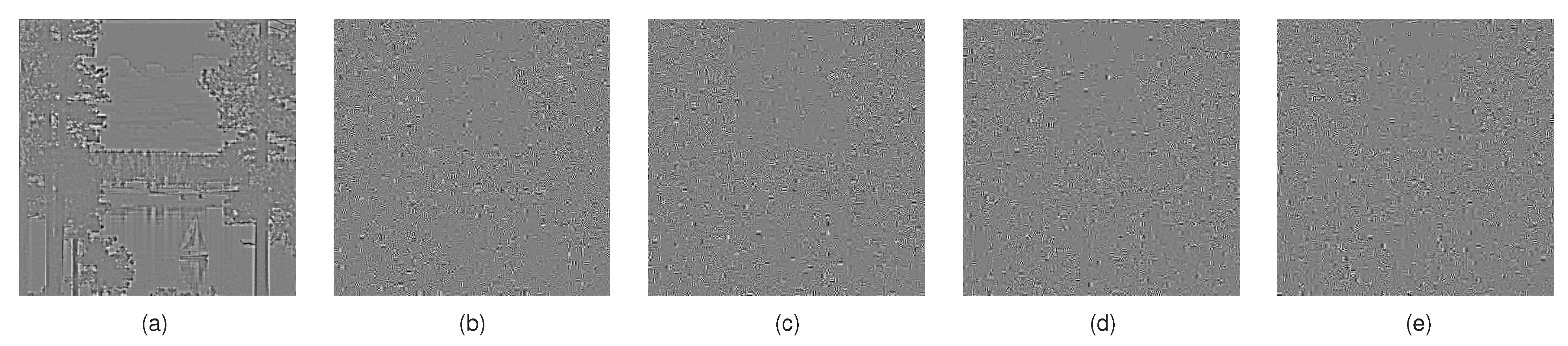
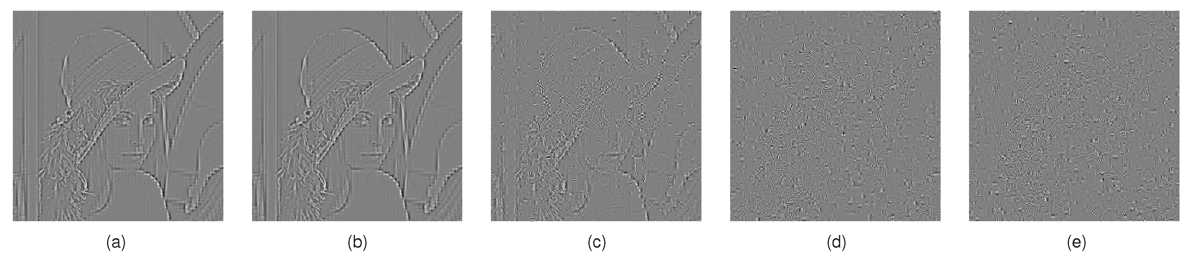
4.1. CPA Effectiveness Using Single-Permutation Method

For several target images, chosen plaintext attacks were performed using the attack algorithm described in [22], and experimental data were collected. Table 1 presents the PSNR values between the recovered images and the original plaintext images with DCC zeroed out under different QF settings. A PSNR value of “Inf” indicates that the recovered image is completely identical to the DC-zeroed plaintext image. In cases where PSNR is not “Inf”, only the baboon image at QF = 65 retains recoverable visual details, while the remaining images fail to reconstruct meaningful content.
Figure 7, Figure 8, Figure 9 and Figure 10 demonstrate the CPA-recovered images under varying QFs (95, 85, 80, 65, and 60).
The results reveal that for images compressed at QF = 95 and QF = 90, the JPEG-encryption scheme proposed in [19] is vulnerable to CPA schemes from [22], posing a security risk of original image detail leakage.

4.2. CPA Effectiveness Using the Additive Value Method

For the same target images, the RCM elimination approach was replaced from the single-permutation method to the additive value method while maintaining the CPA framework from [22]. Table 2 presents the number of RCM-afflicted MCUs before and after applying the additive value method across different QF values for each image. Columns marked with “−” and “+” denote pre- and post-processing data, respectively. A post-processing value of “0” indicates perfect recovery of the DC-zeroed plaintext image, as the permutation sequence Ψ can be fully predicted. Single-digit post-processing values imply minor Ψ prediction errors, allowing for approximate reconstruction of plaintext details, though substantial distortion persists due to cascading errors in predicting permutation sequence Ψ . Post-processing values exceeding 10 preclude meaningful plaintext recovery.
Table 3 compares PSNR values between recovered and DC-zeroed plaintext images under varying QFs. Compared to Table 1, all QF = 85 cases now achieve PSNR = Inf (perfect recovery). For QF = 80, “lake” and “lena” show higher PSNR values, indicating partial detail recovery with residual errors, while “boat"” (QF = 80) and “baboon” (QF = 65) now reach PSNR = Inf. The remaining results align with Table 1.
Figure 11, Figure 12, Figure 13 and Figure 14 display recovered images at QFs spanning 95 to 60.
The improved CPA scheme enables complete DC-zeroed plaintext recovery for all four test images at QF = 95–85. Partial recovery occurs at QF = 80, with some images fully reconstructed and others retaining major features. No meaningful recovery emerges below QF = 80.
To further validate the improved CPA’s generalizability, 100 additional 512 × 512 images were compressed at QF = 95/85 and subjected to the modified attack. Figure 15 (QF = 95) and Figure 16 (QF = 85) plot each image’s PSNR against its RCM MCU count.
As evidenced in Figure 15 and Figure 16, the improved CPA scheme achieved a 79% complete recovery rate for the 100 test images at QF = 95, while the rate decreased to 41% at QF = 85. The results further demonstrate that even minimal prediction errors in permutation sequence Ψ , caused by a small number of residual RCM MCUs, can significantly degrade the information recovery quality of the reconstructed images.
Moreover, in the case of a color image, the three channels (Y, Cb, and Cr) are processed separately. Thus, during the attack, each channel is independently recovered. Successful recovery requires the correct permutation sequence for all three channels to match their original order. Consequently, the probability of a successful attack is significantly lower compared to a gray-scale image.

4.3. Factors Affecting the Effectiveness of the Improved CPA Scheme

The experimental results demonstrate that the effectiveness of the CPA scheme is strongly correlated with the prediction accuracy of Ψ . When Ψ is predicted with complete accuracy, all plaintext image details can be fully recovered. If the prediction contains only a few errors (single-digit inaccuracies), partial plaintext details may still be obtained, and these errors can potentially be manually corrected through exhaustive search methods. However, if the prediction involves errors affecting more than 10 MCUs, the resulting image will essentially fail to reflect any meaningful plaintext details.
The key determinant of Ψ prediction accuracy is the number of RCM-afflicted MCUs that remain unresolved after applying the additive value method. Statistical analysis reveals that these residual RCM MCUs primarily consist of two types:
(1) MCUs with All-Zero ACCs: These MCUs contain exclusively zero-valued ACCs, resulting in an empty run sequence ( R = { } ). To preserve the target image’s MCU histogram integrity, such MCUs cannot be modified. Consequently, all Type 1 MCUs retain their RCM status. Lower-QF images exhibit higher quantities of these MCUs because their larger quantization table values more frequently produce all-zero MCUs during the division process. This explains why the improved CPA scheme maintains poor performance for highly compressed (low-QF) images.
(2) MCUs with Single Non-Zero ACC: These MCUs contain exactly one non-zero ACC of arbitrary value. The additive value method can eliminate RCM for a maximum of only 62 such MCUs. In low-QF images, the count of these MCUs often exceeds 62, leaving residual RCM phenomena in the remainder.
These two types of MCUs have a higher probability under low-QF conditions because the values in the quantization table are generally larger. This, in turn, reduces the accuracy of Ψ prediction, thereby increasing the difficulty of successfully chosen-plaintext attacks.
Figure 17 presents the composition of RCM MCUs across 100 test images at QF = 85. The blue segments represent “all-zero ACC” MCUs, orange segments denote “single non-zero ACC” MCUs, and gray segments indicate other MCU types. The visualization confirms that RCM MCUs in most images consist entirely of these two dominant types.

5. Conclusions

This study indicates that the JPEG encryption algorithm in [19] is vulnerable to chosen plaintext attacks due to the RCM phenomenon and MCU histogram invariance. Higher-QF images have a higher probability of successful chosen plaintext attacks. Moreover, the proposed CPA scheme, although primarily designed for gray-scale images, can be applied to color images as well, but with a lower attack success rate.
While the adaptive key generation in [19] reduces key management complexity, it also introduces potential security risks, as the retained image information can be exploited by attackers. This suggests that the studied JPEG encryption algorithm, while providing some level of protection against known-plaintext attacks, is not robust enough for scenarios where chosen-plaintext attacks are a concern. Future research could focus on optimizing the adaptive key generation strategy to balance key management cost and security.

Author Contributions

Conceptualization, J.H. and K.G.; methodology, K.G. and J.H.; software, K.G.; validation, Y.H., J.H., and Y.L.; formal analysis, J.H.; investigation, J.H.; resources, Y.L.; data curation, K.G.; writing—original draft preparation, K.G. and Y.H.; writing—review and editing, J.H. and Y.L.; visualization, K.G.; supervision, Y.L.; project administration, Y.L. and X.C.; funding acquisition, Y.L. and X.C. All authors have read and agreed to the published version of the manuscript.

Funding

This research was funded by the Guangdong Natural Science Foundation under grant number 2024A1515010137 and was funded in part by the National Natural Science Foundation of China under grant 62476096.

Data Availability Statement

The supporting data for this manuscript are available upon request directly from the author.

Conflicts of Interest

The authors declare no conflicts of interest. The funders had no role in the design of the study; in the collection, analyses, or interpretation of data; in the writing of the manuscript; or in the decision to publish the results.

References

  1. Coppersmith, D. The Data Encryption Standard (DES) and its strength against attacks. IBM J. Res. Dev. 1994, 38, 243–250. [Google Scholar] [CrossRef]
  2. Wright, M.A. The advanced encryption standard. Netw. Secur. 2001, 2001, 11–13. [Google Scholar] [CrossRef]
  3. Li, P.; Lo, K. A content-adaptive joint image compression and encryption scheme. IEEE Trans. Multimed. 2018, 20, 1960–1972. [Google Scholar] [CrossRef]
  4. Li, P.; Lo, K.T. Joint image encryption and compression schemes based on 16 × 16 DCT. J. Vis. Commun. Image Represent. 2019, 58, 12–24. [Google Scholar] [CrossRef]
  5. Peng, Y.; Fu, C.; Cao, G.; Song, W.; Chen, J.; Sham, C.W. JPEG-compatible Joint Image Compression and Encryption Algorithm with File Size Preservation. ACM Trans. Multimed. Comput. Commun. Appl. 2024, 20, 1–20. [Google Scholar] [CrossRef]
  6. Cheng, H.; Xiaobo, L. On the application of image decomposition to image compression and encryption. In Proceedings of the IFIP TC6/TC11 International Conference on Communications and Multimedia Security II, Essen, Germany, 23–24 September 1996; pp. 116–127. [Google Scholar] [CrossRef]
  7. Massoudi, A.; Lefebvre, F.; De Vleeschouwer, C.; Macq, B.; Quisquater, J.J. Overview on selective encryption of image and video: Challenges and perspectives. EURASIP J. Inf. Secur. 2008, 2008, 179290. [Google Scholar] [CrossRef]
  8. Puech, W.; Rodrigues, J. Crypto-compression of medical images by selective encryption of DCT. In Proceedings of the 13th European Signal Processing Conference, Antalya, Turkey, 4–8 September 2005; pp. 1–4. [Google Scholar]
  9. Pinto, M.; Puech, W.; Subsol, G. Protection of JPEG compressed E-comics by selective encryption. In Proceedings of the 20th IEEE International Conference on Image Processing (ICIP 2013), Melbourne, VIC, Australia, 15–18 September 2013; pp. 4588–4592. [Google Scholar] [CrossRef]
  10. Lian, S. Efficient image or video encryption based on spatiotemporal chaos system. Chaos Solitons Fractals 2009, 40, 2509–2519. [Google Scholar] [CrossRef]
  11. Khan, N.A.; Altaf, M.; Khan, F.A. Selective encryption of JPEG images with chaotic based novel S-box. Multimed. Tools Appl. 2021, 80, 9639–9656. [Google Scholar] [CrossRef]
  12. Li, P.; Meng, J.; Sun, Z. A new JPEG encryption scheme using adaptive block size. In Advances in Intelligent Information Hiding and Multimedia Signal Processing: Proceeding of the 16th International Conference on IIHMSP in Conjunction with the 13th International Conference on FITAT, Ho Chi Minh City, Vietnam, 5–7 November 2020; Springer: Singapore, 2021; Volume 211, pp. 140–147. [Google Scholar] [CrossRef]
  13. Li, S.; Zhang, Y. Quantized DCT coefficient category address encryption for JPEG image. KSII Trans. Internet Inf. Syst. 2016, 10, 1790–1806. [Google Scholar]
  14. Auer, S.; Bliem, A.; Engel, D.; Uhl, A.; Unterweger, A. Bitstream-based JPEG encryption in real-time. Int. J. Digit. Crime Forensics 2013, 5, 1–14. [Google Scholar] [CrossRef]
  15. Puteaux, P.; Yriarte, F.; Puech, W. A secret JPEG image sharing method over GF(2M) galois fields. IEEE Trans. Circuits Syst. Video Technol. 2022, 33, 3030–3042. [Google Scholar] [CrossRef]
  16. Yuan, Y.; He, H.; Yang, Y.; Mao, N.; Chen, F.; Ali, M. JPEG image encryption with grouping coefficients based on entropy coding. J. Vis. Commun. Image Represent. 2023, 97, 103975. [Google Scholar] [CrossRef]
  17. Li, P.; Lo, K.T. Survey on JPEG compatible joint image compression and encryption algorithms. IET Signal Process. 2020, 14, 475–488. [Google Scholar] [CrossRef]
  18. Li, C. When an attacker meets a cipher-image in 2018: A year in review. J. Inf. Secur. Appl. 2019, 48, 102361. [Google Scholar] [CrossRef]
  19. He, J.; Huang, S.; Tang, S.; Huang, J. JPEG image encryption with improved format compatibility and file size preservation. IEEE Trans. Multimed. 2018, 20, 2645–2658. [Google Scholar] [CrossRef]
  20. Cardona-López, M.A.; Chimal-Eguía, J.C.; Silva-García, V.M.; Flores-Carapia, R. Statistical Analysis of the Negative–Positive Transformation in Image Encryption. Mathematics 2024, 12, 908. [Google Scholar] [CrossRef]
  21. Chen, J.; Chen, L.; Zhou, Y. Universal chosen-ciphertext attack for a family of image encryption schemes. IEEE Trans. Multimed. 2021, 23, 2372–2385. [Google Scholar] [CrossRef]
  22. He, H.; Yuan, Y.; Ye, Y.; Tai, H.M.; Chen, F. Chosen Plaintext Attack on JPEG Image Encryption with Adaptive Key and Run Consistency. J. Vis. Commun. Image Represent. 2023, 90, 103733. [Google Scholar] [CrossRef]
  23. Yuan, Y.; He, H.; Chen, F. On the security of encrypted JPEG image with adaptive key generated by invariant characteristic. In Digital Forensics and Watermarking: 20th International Workshop, IWDW 2021, Beijing, China, 20–22 November 2021; Springer: Cham, Switzerland, 2022; Volume 13180, pp. 58–71. [Google Scholar] [CrossRef]
  24. Benrhouma, O.; Hermassi, H.; El-Latif, A.A.A.; Belghith, S. Cryptanalysis of a video encryption method based on mixing and permutation operations in the DCT domain. Signal Image Video Process. 2015, 9, 1281–1286. [Google Scholar] [CrossRef]
  25. Lee, M.K.; Jang, E.S. Cryptanalysis of start code-based encryption method for HEVC. IEEE Access Pract. Innov. Open Solut. 2021, 9, 92568–92577. [Google Scholar] [CrossRef]
  26. Preishuber, M.; Hütter, T.; Katzenbeisser, S.; Uhl, A. Depreciating motivation and empirical security analysis of chaos-based image and video encryption. IEEE Trans. Inf. Forensics Secur. 2018, 13, 2137–2150. [Google Scholar] [CrossRef]
  27. Li, C.; Lin, D.; Feng, B.; Lü, J.; Hao, F. Cryptanalysis of a chaotic image encryption algorithm based on information entropy. IEEE Access Pract. Innov. Open Solut. 2018, 6, 75834–75842. [Google Scholar] [CrossRef]
  28. Feng, W.; He, Y. Cryptanalysis and improvement of the hyper-chaotic image encryption scheme based on DNA encoding and scrambling. IEEE Photonics J. 2018, 10, 1–15. [Google Scholar] [CrossRef]
  29. Xiang, T.; Guo, S.; Li, X. Perceptual visual security index based on edge and texture similarities. IEEE Trans. Inf. Forensics Secur. 2016, 11, 951–963. [Google Scholar] [CrossRef]
  30. Wu, Y.; Zhou, Y.; Saveriades, G.; Agaian, S.; Noonan, J.P.; Natarajan, P. Local shannon entropy measure with statistical tests for image randomness. Inf. Sci. 2013, 222, 323–342. [Google Scholar] [CrossRef]
  31. Chuman, T.; Kiya, H. Security evaluation for block scrambling-based image encryption including JPEG distortion against jigsaw puzzle solver attacks. IEICE Trans. 2018, 101-A, 2405–2408. [Google Scholar] [CrossRef]
  32. Özkaynak, F. Brief review on application of nonlinear dynamics in image encryption. Nonlinear Dyn. 2018, 92, 305–313. [Google Scholar] [CrossRef]
  33. Mitchell, J. Digital Compression and Coding of Continuous-Tone Still Images: Requirements and Guidelines; ITU-T Recommendation T.81; International Telecommunication Union: Geneva, Switzerland, 1992; Available online: https://www.itu.int/rec/T-REC-T.81-199209-I/en (accessed on 28 May 2025).
Figure 1. Plaintext image O, image O , ciphertext image E. ( Ψ = { 3 , 1 , 2 } , Π 0 = { 5 , 2 , 4 , 1 , 3 } , Π 1 = { 2 , 4 , 3 , 1 } ).
Jsan 14 00072 g001
Figure 2. The constructed non-zero ACC of image (A) and (B) when two plaintext images are needed.
Jsan 14 00072 g002
Figure 3. The overall process of the original CPA scheme when x = 2.
Jsan 14 00072 g003
Figure 4. Run sequences of z after the additive value method—all run sequences are unique. (a) z = 6 ; (b) z = 8 ; (c) z = 282 .
Jsan 14 00072 g004
Figure 5. Run sequences of 8 MCUs after the additive value method—run sequence { 56 , 1 , 0 , 0 , 1 } already exists.
Jsan 14 00072 g005
Figure 6. The overall process of the improved CPA scheme when x = 2.
Jsan 14 00072 g006
Figure 7. The decrypted image of lake (single-permutation method). (a) QFs = 95; (b) QFs = 85; (c) QFs = 80; (d) QFs = 65; (e) QFs = 60.
Jsan 14 00072 g007
Figure 8. The decrypted image of lena (single-permutation method). (a) QFs = 95; (b) QFs = 85; (c) QFs = 80; (d) QFs = 65; (e) QFs = 60.
Jsan 14 00072 g008
Figure 9. The decrypted image of boat (single-permutation method). (a) QFs = 95; (b) QFs = 85; (c) QFs = 80; (d) QFs = 65; (e) QFs = 60.
Jsan 14 00072 g009
Figure 10. The decrypted image of baboon (single-permutation method). (a) QFs = 95; (b) QFs = 85; (c) QFs = 80; (d) QFs = 65; (e) QFs = 60.
Jsan 14 00072 g010
Figure 11. The decrypted image of lake (additive value method). (a) QFs = 95; (b) QFs = 85; (c) QFs = 80; (d) QFs = 65; (e) QFs = 60.
Jsan 14 00072 g011
Figure 12. The decrypted image of lena (additive value method). (a) QFs = 95; (b) QFs = 85; (c) QFs = 80; (d) QFs = 65; (e) QFs = 60.
Jsan 14 00072 g012
Figure 13. The decrypted image of boat (additive value method). (a) QFs = 95; (b) QFs = 85; (c) QFs = 80; (d) QFs = 65; (e) QFs = 60.
Jsan 14 00072 g013
Figure 14. The decrypted image of baboon (additive value method). (a) QFs = 95; (b) QFs = 85; (c) QFs = 80; (d) QFs = 65; (e) QFs = 60.
Jsan 14 00072 g014
Figure 15. The attack results on 100 JPEG images with QF = 95.
Jsan 14 00072 g015
Figure 16. The attack results on 100 JPEG images with QF = 85.
Jsan 14 00072 g016
Figure 17. The composition of the MCUs with RCM in 100 constructed plaintext images with QF = 85.
Jsan 14 00072 g017
Table 1. The PSNR of ACC between original images and attacked images (single-permutation method).
QFsLakeLenaBoatBaboon
95InfInfInfInf
90InfInfInfInf
8514.7617.99InfInf
8015.1218.2416.46Inf
7515.6318.9717.03Inf
7015.9619.1517.18Inf
6516.0919.1617.1936.13
6016.3219.4217.59Inf
Table 2. The number of MCUs with RCM in the constructed plaintext image before and after the additive value method is used.
QFsLake−Lake+Lena−Lena+Boat−Boat+Bab−Bab+
9540000000
902004802000
851520287045000
8038448672207060
75597341300255331860
7079298169716285693200
6594918920293871140187400
60115427722236021345310730
Table 3. The PSNR of ACC between original images and attacked images (additive value method).
QFsLakeLenaBoatBaboon
95InfInfInfInf
90InfInfInfInf
85InfInfInfInf
8019.0220.92InfInf
7515.7219.0617.09Inf
7015.9319.1517.16Inf
6516.1119.2517.34Inf
6016.3619.4317.56Inf
Disclaimer/Publisher’s Note: The statements, opinions and data contained in all publications are solely those of the individual author(s) and contributor(s) and not of MDPI and/or the editor(s). MDPI and/or the editor(s) disclaim responsibility for any injury to people or property resulting from any ideas, methods, instructions or products referred to in the content.

