1. Introduction
Since the late 1990s, the use of the GNSS (Global Navigation Satellite Systems) aided inertial navigation in mobile mapping industry has revolutionarily changed the way how to geo-reference the geo-spatial data. This is well known as direct geo-referencing technology in the field of Geomatics. However, the high expenses of the high-end inertial measurement units (IMU) and the commercial hard real-time operating system (RTOS) greatly hinder many researchers and engineers from their activities in the navigation area. This paper presents a fast and economical solution for the development of the core component of the direct geo-referencing multisensor system: a low cost kinematic positioning and navigation system focusing on the real-time data acquisition and the post-processing GPS-aided inertial integrated navigation solution.
In comparison with the high-end IMU unit in the commercial navigation systems, the low cost Micro-Electro-Mechanical Systems (MEMS)-based IMU is more attractive in practice. The error modeling and inertial sensor integration algorithms for the MEMS-based IMUs have been discussed for years [
1,
2,
3,
4,
5,
6,
7,
8]. Technically, with aiding sensors such as GPS receivers or odometers, the rapid-growing navigation solution errors in a low cost land vehicle system can be constrained within a level of meters [
9]. In terms of the RTOS, numerous low cost systems employ an open and free soft real-time Linux system as a compromised economical alternative. Nevertheless, the strict hard real-time requirement more or less limits its usage in a kinematic positioning and navigation system which needs to collect and process the sensor data strictly within a specified amount of time. Inspired by the successful precedents in [
10,
11], a low cost kinematic positioning and navigation system based on Linux/RTAI integrating the low cost MEMS-based IMU and OEM GPS sensors was designed and developed in the Earth Observation Laboratory (EOL) at York University. RTAI, as one of the main real-time Linux variants, has demonstrated its competitive hard real-time performance vs. other commercial counterparts in many industrial applications [
12]. Another advantage of RTAI with the LXRT (Linux Real Time) feature is that the development cost and time can greatly be reduced. Refer to [
13] for the definition of the soft and hard real-time systems.
This paper presents a panoramic view of the low cost multisensor kinematic positioning and navigation system featuring Linux/RTAI along with system hardware platform, real-time operating system, software framework, time synchronization strategies and post-processing GPS-aided inertial integrated navigation algorithms for direct geo-referencing purposes. Following the introduction, the system hardware platform is introduced in
Section 2. After the Linux/RTAI software package is summarized in
Section 3,
Section 4 describes the generic software architecture of a multisensor positioning and navigation system involving multiple GPS receivers and one IMU unit. Multiple time synchronization strategies are discussed in
Section 5. Finally,
Section 6 presents two road tests with their setup and our goal solutions: the post-processed kinematic positioning and navigation solutions at an accuracy level of centimeters based on the loosely-coupled GPS-aided inertial integrated navigation architecture.
2. Navigation Hardware System
In general, the control unit in a kinematic positioning and navigation system dealing with massive data traffic and heavy computation load requires multi-tasking capability, accurate timing, powerful CPU, and flexible sensor accessibility. Fortunately, all of above requirements are no longer barriers for modern personal laptops and desktops capable of hundreds of times faster computing performance than the control unit in an old navigation system.
The positioning and navigation system developed in the EOL lab at York University consists of a MEMS IMU and two OEM GPS receivers together with the third GPS receiver as a base station, which is currently being extended to integrate two digital cameras for research in visual simultaneous localization and mapping (SLAM) and visual odometry. The prototype of our integrated navigation system was developed on both a Dell personal laptop and a mini control board system with Intel Atom CPU. The laptop model is Dell XPS 1,530 with 2.2 GHz Core-2-Duo T7500 processor and an express-card serial adapter is installed to provide two extra serial ports. A Jetway motherboard (NF94-270-LF) equipped with 1.6 GHz Intel Atom N270 CPU is the second platform with a power consumption as low as 15 Watt. This control board has rich peripheral interfaces including four RS232 serial ports, four USB 2.0 ports, one Parallel port, one LAN port, and one1 PCI expansion slot. On both platforms, Ubuntu Linux (10.04 LTS) with Real Time Application Interface (RTAI 3.8.1) was installed as their operating system.
Moreover, a navigation system needs to work under a hard real-time operating system environment since it has to handle multiple tasks within a certain time constraint to avoid time latency. In
Section 3 the Linux/RTAI real-time system is investigated for its application on our low cost navigation system.
3. RTAI Linux
3.1. Real Time Linux
Michael [
14] first developed the real-time feature into the Linux system with the concept design and implemented RTLinux in 1996. His work was acquired by Wind River in 2007 and converted into the commercial Wind River Linux. Another main real-time Linux variant is RTAI independently developed by DIAPM (Dipartimento di Ingegneria Aerospaziale—Politecnico di Milano) in 2000 [
15]. There have been many successful RTAI applications implemented on computer numerical control machines in the manufacturing industry. Linux/RTAI is used in our system because it is free and well maintained by the RTAI team. Refer to website:
www.rtai.org for more details about its development.
3.3. Task Management
By default, a RTAI task is registered as a soft real-time task [
14]. The behaviors of a soft real-time RTAI task is exactly the same as a Linux thread except its communication capability with other RTAI hard/soft real-time threads/modules. In order to achieve the superior execution priority to all other Linux tasks, all tasks with hard real-time requirements need to be registered as hard real-time RTAI tasks as opposed to the soft real-time RTAI tasks under the RTAI system.
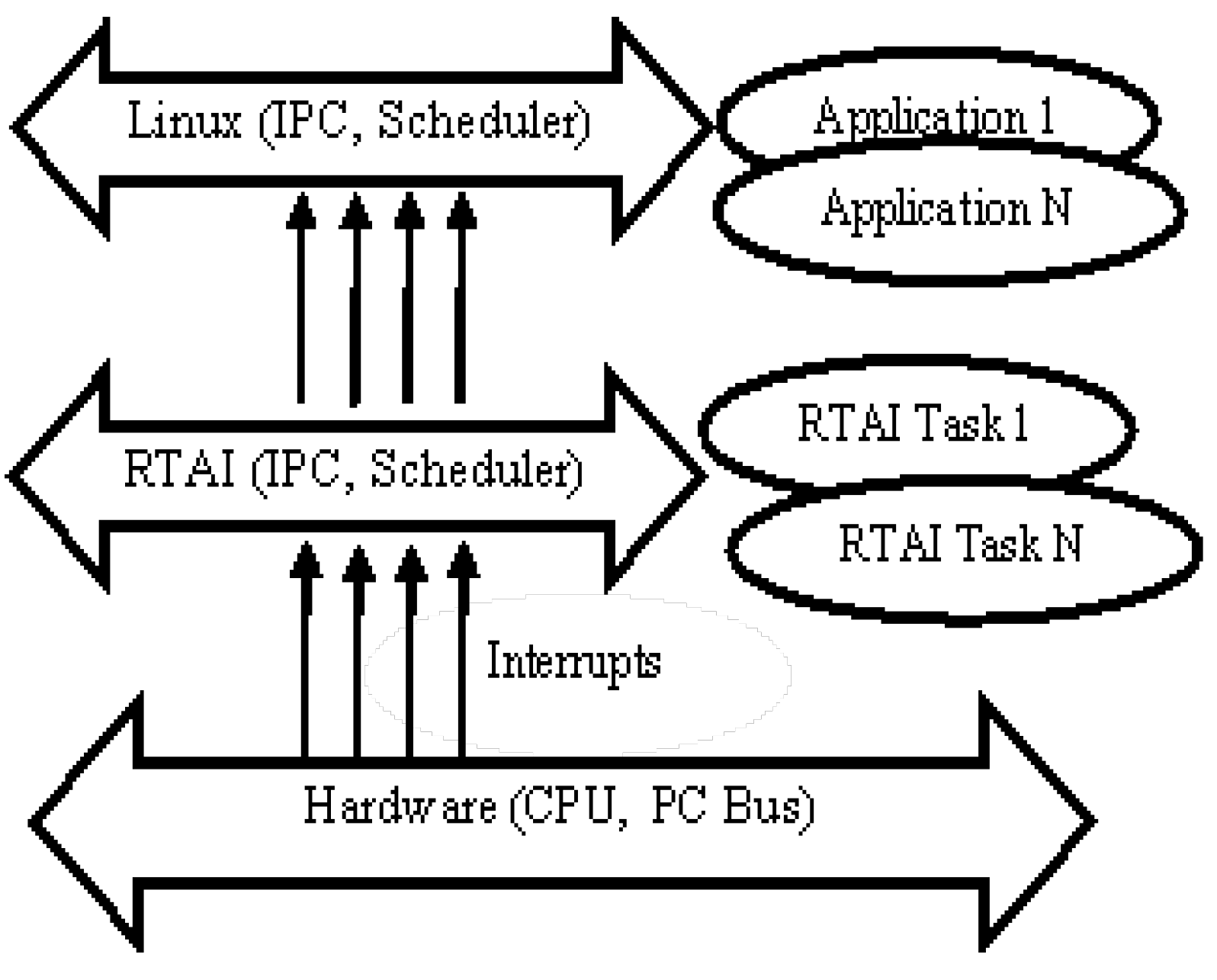
Figure 2 shows that a RTAI scheduler and a Linux scheduler exist in parallel. By modifying the interrupt dispatcher, the RTAI scheduler seizes a higher priority than the Linux scheduler does while handling the peripherals’ interrupts (hard external interrupt, timer, signal, message,
etc.) [
15]. After the corresponding RTAI tasks finish their work, the RTAI scheduler hands over the CPU to the Linux scheduler. So, the existence of hard real-time RTAI tasks is transparent for all other Linux programs. This architecture not only allows our system to take the advantages of all existing Linux features it also balances the distribution of CPU power on the Linux programs and the real-time RTAI tasks.
Figure 2.
RTAI architecture (Adapted from [
15]).
Figure 2.
RTAI architecture (Adapted from [
15]).
3.4. LXRT Service/Module
LXRT service is a special software module of RTAI allowing the implementation of a hard real-time thread/module under the user space environment. A hard real-time RTAI module is usually coded as a kernel module in order to access the hardware and be executed with hard real-time performance. However, the system may crash simply due to one careless instruction from the real-time module in the kernel space. As a main advantage of LXRT, a real-time RTAI module can be realized under the user space LXRT environment and also use all the application programming interface (API) available in the user space [
17]. In addition, one can employ the luxury of a user space graphic debugger to debug the hard real-time module without worrying about the system crash. Moreover, it is very convenient to convert a Linux application into a RTAI/LXRT application because only a few lines of the source codes are needed. Refer to [
17,
18] for details about the LXRT and its realization in the Linux/RTAI.
In theory, a LXRT hard real-time module consumes a few more microseconds than a traditional hard real-time module does. However, because the influences of the time latency at the microsecond level are insignificant for the land vehicle kinematic positioning and navigation system, a user space LXRT module can be a full substitute for the RTAI kernel module in terms of its functionality and performance. More discussions about the effect of the time latency on the final navigation solutions can be seen in
Section 5.
4. Navigation System Software Architecture
4.1. Navigation System Framework
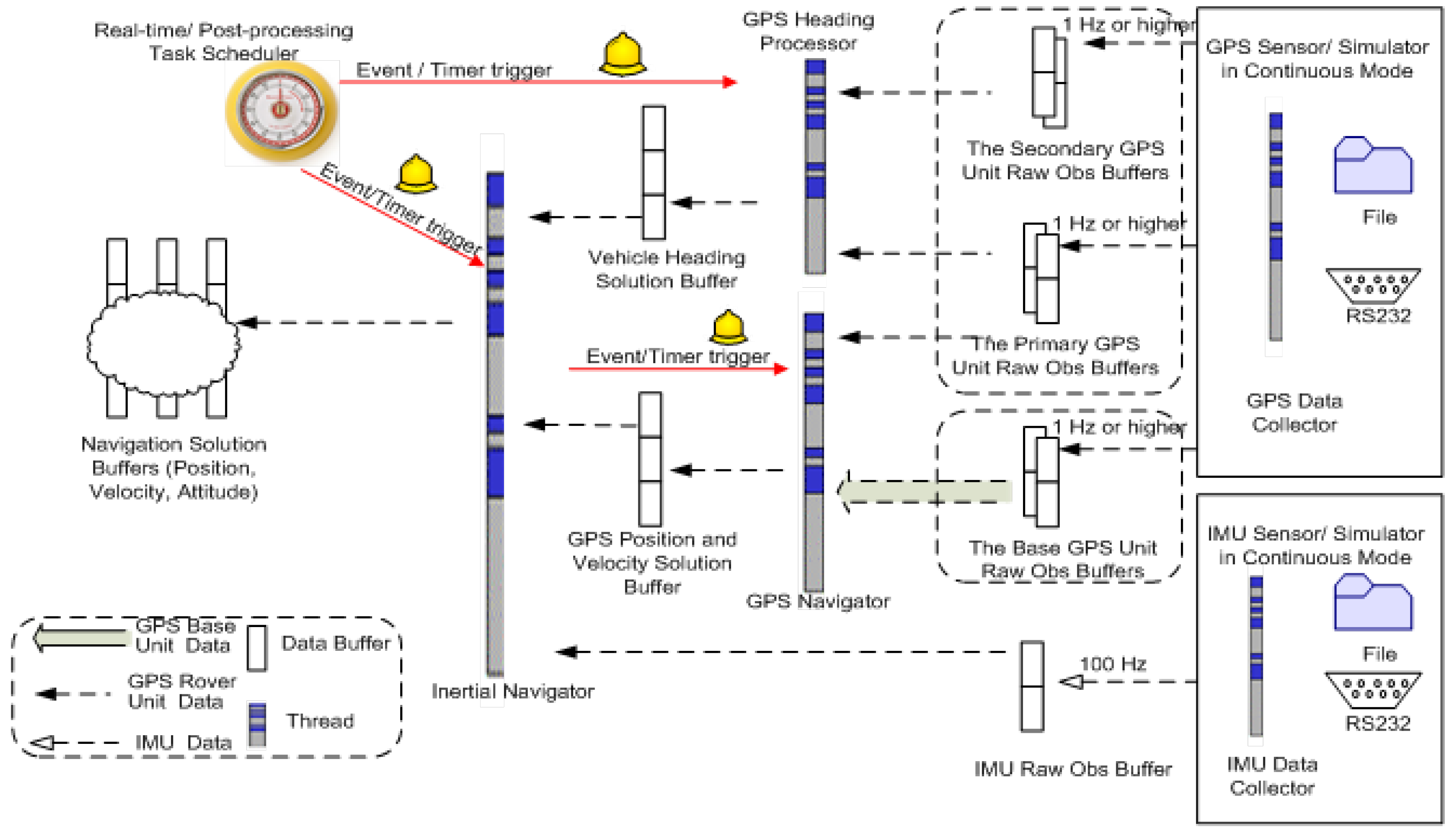
To simplify the software structure of the positioning and navigation system dealing with two processing modes (the real-time mode and the post-processing mode), we propose one unified software architecture with its two different concrete realizations. The developed integrated navigation system provides three main software modules: data collector, navigator (processor) and the data buffer.
Figure 3 presents the software architecture of the navigation system.
Figure 3.
Software architecture of navigation system.
Figure 3.
Software architecture of navigation system.
In the real-time mode, both the data collector and the navigator deal with the sensor data directly from the hardware under the hard real-time environment. On the other hand, the data collector in the post-processing mode reads the sensor measurements from the file and the navigator/processor is executed without concerning the time constraint. Consequently, the inertial navigator in the post-processing mode will not consider the time delay in the feedback correction for the IMU systematic errors due to the lag of the Kalman filter execution. However, this time delay has to be taken into account as an extra source of the process noises for the inertial navigator in real-time mode.
Section 4.2 has more details about the loose-coupled inertial navigator.
In the unified system structure, both of the GPS receivers and the IMU unit (data collectors) periodically (e.g., at 1 Hz and 100 Hz) transmit sensor data to the data collectors. At the same time, the navigator or processor can retrieve and process the raw measurements whenever necessary. The data collectors and the navigators exchange the sensor data through the data buffers such that a clear system structure is maintained. Namely, one data collector module is created for each sensor to collect the sensor measurements and transmit them into a dedicated data buffer which manages the synchronized data access requested by any other threads. The solved GPS solution or the INS solution is then stored in a solution buffer for any further usage.
4.2. GPS and Inertial Navigator
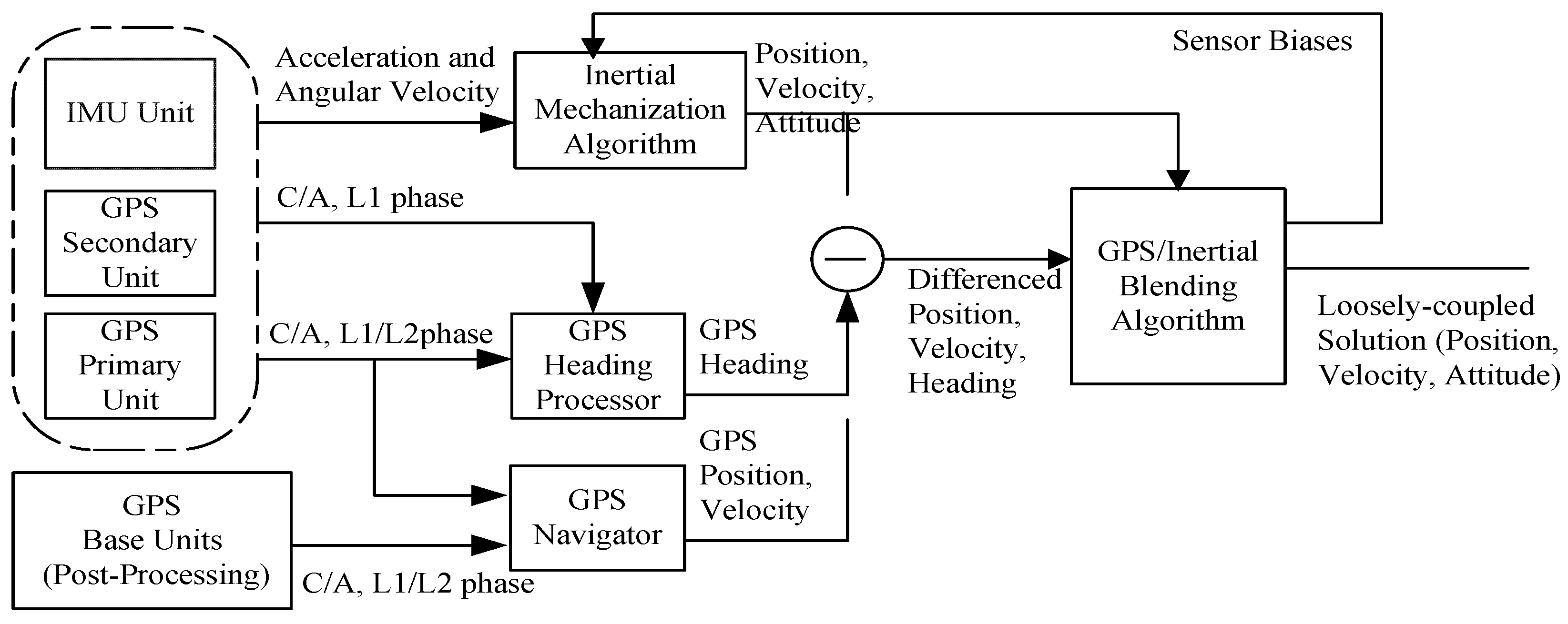
In our system, the measurements from the GPS receivers and the IMU unit are blended by using the loosely-coupled GPS-aided inertial navigation architecture (
Figure 4). Depending on the processing mode, the pseudo range, Doppler and carrier phase observations from the primary GPS receiver in conjunction with or without those from the base station are used to estimate the position and velocity of the vehicle. Besides, the observables from the primary and secondary GPS receivers on the vehicle are used to determine the heading of the vehicle. Because the MEME-based IMU sensors are rigidly strapped to the platform, the INS mechanization is executed with the strapdown inertial navigation strategy [
19] to generate the navigation solutions using the IMU measurements. Next, the differenced solutions between the synchronized GPS solutions and the INS mechanization solution are then treated as aiding measurements in the loosely-coupled GPS-aided inertial navigation Kalman filter. The discussion of the four major modules in the loosely-coupled system (
Figure 4) is given below.
Figure 4.
Loosely-coupled Global Position System (GPS)-aided inertial navigation architecture.
Figure 4.
Loosely-coupled Global Position System (GPS)-aided inertial navigation architecture.
4.2.1. Inertial Mechanization
The INS mechanization [
19] is the essential algorithm to calculate the position, velocity and attitude of the vehicle relative to the target coordinate system. Through angular rate measurements, the attitude angles of the vehicle represented by the direction cosines matrix (DCM) are solved. Similarly, the velocity could be propagated through specific force measurements. Finally, the position is updated based on the solved attitude and velocity of the vehicle. Refer to [
19] for more details about the strapdown INS mechanization for the MEMS-based IMU.
4.2.2. GPS Navigator
The GPS navigator has different realizations in two processing modes. In the post-processing mode, the GPS navigator is actually a Kalman filter with the position-velocity-acceleration (PVA) state model with the jerk vector as the process noise vector. It generates the 1 Hz GPS positioning solution of the primary GPS with respect to the base GPS station by using their dual frequency (L1/L2) measurements including the pseudo range, Doppler and carrier phase observations. However, in the real-time mode, the GPS navigator in our system can only produce the 1 Hz carrier phase smoothed pseudorange single point positioning solutions for now due to lack of communication devices for the transmission of the base station information.
4.2.3. GPS Heading Processor
The heading processor in
Figure 3, as an independent GPS heading Kalman filter with the position-velocity (PV) state model for the three baseline components between the primary and the secondary GPS receivers, is able to estimate the (1 Hz) headings epochwise by using the L1 C/A and carrier phase measurements from the primary and secondary GPS receivers. With a baseline length of 1.780 m between the primary and secondary GPS receivers, the accuracy of the heading estimate can be expected to be better than half a degree. In both of the GPS Kalman filters, the LAMBDA method was implemented to fix the floated ambiguities and subsequently produce the fixed baseline solution [
20].
4.2.4. Inertial Navigator
The developed loosely coupled GPS-aided inertial navigation engine (Inertial navigator) runs its Kalman filter based on the phi-angle inertial navigation error model to estimate the position, velocity and attitude errors together with the accelerometer and gyro biases in its 15-state vector whilst the differences between the synchronized 1 Hz GPS and 1 Hz inertial navigation solutions including positions, velocities and headings are used as the measurements in the loosely-coupled integrated navigation Kalman filter. In turn, estimates of the IMU errors are used to correct the raw IMU measurements to form a closed-loop system. Therefore, synchronizing the sensor is of paramount importance to ensure the correct estimation of the error states in the Kalman filter.
4.3. Data Collector and Associated Data Buffers
The prototype of our integrated navigation system integrated only one IMU unit (Crossbow MEMS NAV440 or IMU800CA) and two NovAtel GPS receivers. The real-time data collector module was designed to run in the asynchronous mode in order to efficiently respond to the incoming data while the data collector in post-processing mode runs in the periodical poll (request-reply) mode without concerning the time. Each sensor data collector manages its own measurements through one internal data buffer. The communication between modules is conducted through reading and writing the data buffers.
To avoid any data corruption and ensure I/O on the same data block in the multiple threads environment, the data buffer is implemented with a mutual exclusive data access (MUTEX) protection mechanism based on the producer-consumer design pattern. It is noted that the size of the buffer (number of blocks) is fixed and large enough to handle the peak data traffic so that the problematic run-time memory allocation and memory release operations are prevented. Thus, the system can gain a higher data I/O speed without concern for notorious memory leak.
5. Time Synchronization in Multisensor Data Acquisition
5.1. General
Time synchronization is to tag the acquired data of multiple sensors with a time stamp in the same time frame, which is essential for kinematic positioning and navigation. In nature, we may use the local computer time frame as the default time frame for all sensors. However, the clock oscillator in the computer suffers from potential drift so that its long term instability cannot satisfy the requirement of a high-accuracy timing system. Furthermore, the navigation module has to present the final navigation solution in an absolute/universal time frame. Consequently, we need to find a stable external clock source with high resolution and long term stability. By periodically synchronizing the local computer time with the high accuracy external clock, the magnitude of the clock drift and instability in local computer can be minimized and becomes ignorable.
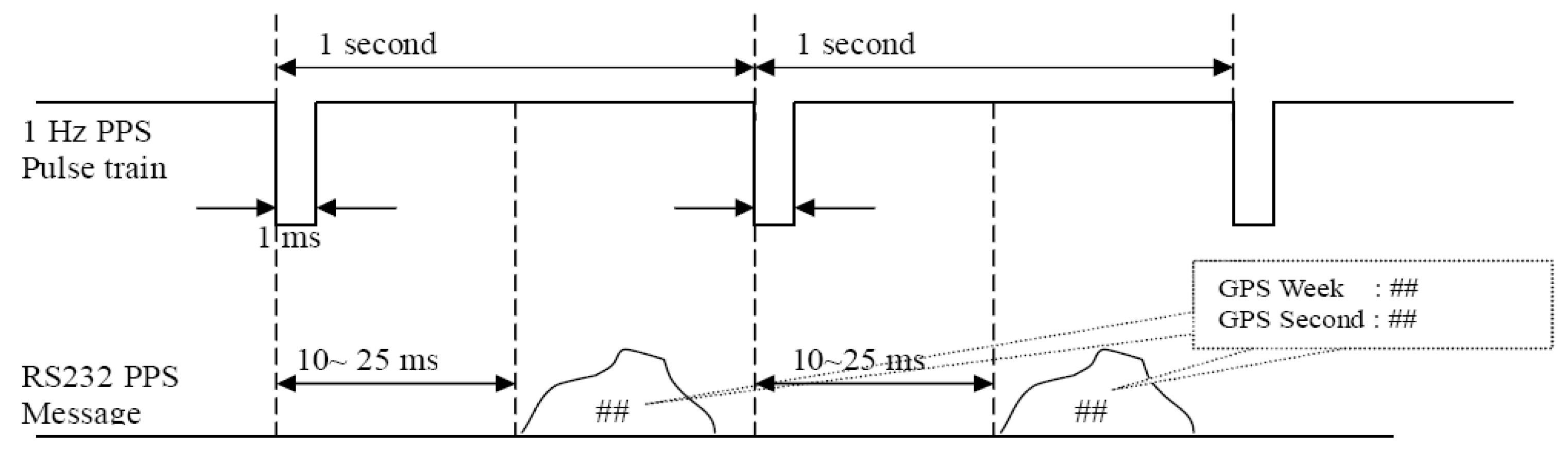
Nowadays the GPS time is a popular time frame for multisensor integrated navigation systems because the high-accuracy 1 Hz PPS hard signal can be easily retrieved from a GPS unit, for example, 50 ns accuracy from the NovAtel GPS OEM unit. Physically, the 1 Hz PPS signal (
Figure 5) as the timing signal is nothing but a square wave (pulse) with 1 ms width [
18]. The absolute GPS time corresponding to the left dropping edge is conveyed in the special PPS message dispatched from the GPS receiver. Subsequently, the GPS time for data acquired from other sensors can be computed as follows:
where Tsensor is the sensor data time stamp in the GPS time frame, tlocal is the local computer time stamp in the sensor data packet, tPPS is the local computer time stamp for 1 Hz PPS pulse, and TPPS is the time stamp in the GPS time frame corresponding to the 1 Hz PPS.
Figure 5.
PPS signal and message diagram (Adapted from [
21]).
Figure 5.
PPS signal and message diagram (Adapted from [
21]).
In general, two tasks need to be completed for the time synchronization: GPS time import into our system whenever the GPS time is available and time tagging the sensor data using GPS time.
5.2. GPS Time Import
In our navigation system, a global variable named “PPS_struct” is normally updated at 1 Hz, for instance, in order to maintain the relationship between the true GPS time and the synchronous local computer time. Through interpreting the 1 Hz PPS signal using both the local computer time and the GPS time, the GPS time import is accomplished and the clock drift is restrained. Two different methods for two different hardware platforms are given below in this section respectively.
5.2.1. Mini Control Board
On the Jetway mini control board platform, the PPS signal is hardwired into the pin #10 of the parallel port to trigger the interrupt IRQ7, whose handler retrieves the current local computer time using the Linux system API function “clock_gettime” and assigns it into the variable “PPS_struct”. This time stamp with a lag of a few tens of microseconds due to the interrupt response delay (10~30 μs) is the most accurate representation of the PPS signal in the local computer frame. The GPS time of the PPS signal is then captured through the RS232 serial port later (e.g., about 20 ms with NovAtel OEM GPS receivers). Herein lies the connection between the GPS time and the computer time.
5.2.2. Dell Laptop XPS1530
As the Dell laptop XPS1530 does not have accessibility to the external hardware interrupt, the 1 Hz PPS hard signal is directly hardwired into the CTS pin of a dedicated RS232 serial port in the express-card serial port adapter. Instead of passively waiting for the PPS interrupt signal, the PPS hard signal is actively detected by periodically reading the electronic signal level on the CTS pin triggered by a 50 μs RTAI timer. Because the jitter of the RTAI timer (the duration change of a timer period) is approximately 30 μs~50 μs, the GPS time import using the serial port can achieve an accuracy of 100 μs, which is practically good enough for our low cost kinematic positioning and navigation system according to the analysis in Section III of [
22]. For a land vehicle, the effect of the maximum jerk of 4 m/s
3 on the predicted state vector in the Kalman filter is too small to bias the final navigation solution because the product of the timing error and the jerk of a moving vehicle is ten times smaller than the absolute magnitude of the system innovation in the loosely-coupled GPS-aided integrated Kalman filter. As a result, the error in the final navigation solution could become numerically ignorable. For the same reason, that timing error can also be ignored in the INS mechanization module.
5.3. Sensor Data Time Stamp
In the second stage of time synchronization, a time stamp for the sensor measurement needs to be tagged at the exact time instant when the sensor measurements are taken. This job has been done in the GPS receivers for all GPS measurements while it has to be taken by the control unit for all IMU data acquired either from a RS232 serial port or the analog signal pins. Without loss of generality, only the time synchronization solution for the Crossbow MEMS IMU units is discussed here. Two types of measurements are supported with the Crossbow MEMS IMU sensors: continuous analog signal and digital data packet. In both situations, the time delay due to data acquisition and transmission has to be taken into account.
According to the Crossbow DMU (Dynamic Measurement Unit) manuals [
23,
24], the digital data packet mode will sequentially experience three stages: sampling (T1), processing (T2) and transferring (T3). Whereas the sensor data are presented immediately on the analog output pins after the processing step (T2) is over when a Crossbow DMU is working in the continuous analog signal mode. The analog output has a time delay of 2.3 ms with the 400 Hz output rate while the scaled digital packet has a time delay of 6.4 ms with the working frequency 156 Hz (
Table 1).
Table 1.
IMU300 Series, IMU400 Series and VG300CB Timing (Data from [
24]).
Table 1.
IMU300 Series, IMU400 Series and VG300CB Timing (Data from [24]).
| Operating Mode | Sampling | Processing | Transferring | Total delay | Max Rate |
|---|
| Voltage | 0.8 ms | 0.5 ms | 4.7 ms | 6.0 ms | 166 Hz |
| Scaled | 0.8 ms | 0.9 ms | 4.7 ms | 6.4 ms | 156 Hz |
| VG(VGX only) | 0.8 ms | 1.5 ms | 5.2 ms | 7.5 ms | 133 Hz |
| Analog Output | 0.8 ms | 1.5 ms | - | 2.3 ms | 400 Hz |
In our low cost system, the initial local computer time stamps are assigned to the packets when the digital IMU data are acquired from the serial port. In theory, three strategies can be used for further calibration of these initial time stamps: hardware alignment [
25], software processing [
26,
27] and online correction with known constants. In our system, the known timing error constant (
Table 1) is directly applied to the initial time stamp of the raw IMU measurements according to the same analysis of the timing error presented in the
Section 5.2.2.
6. Road Tests and Results
6.1. System Setup
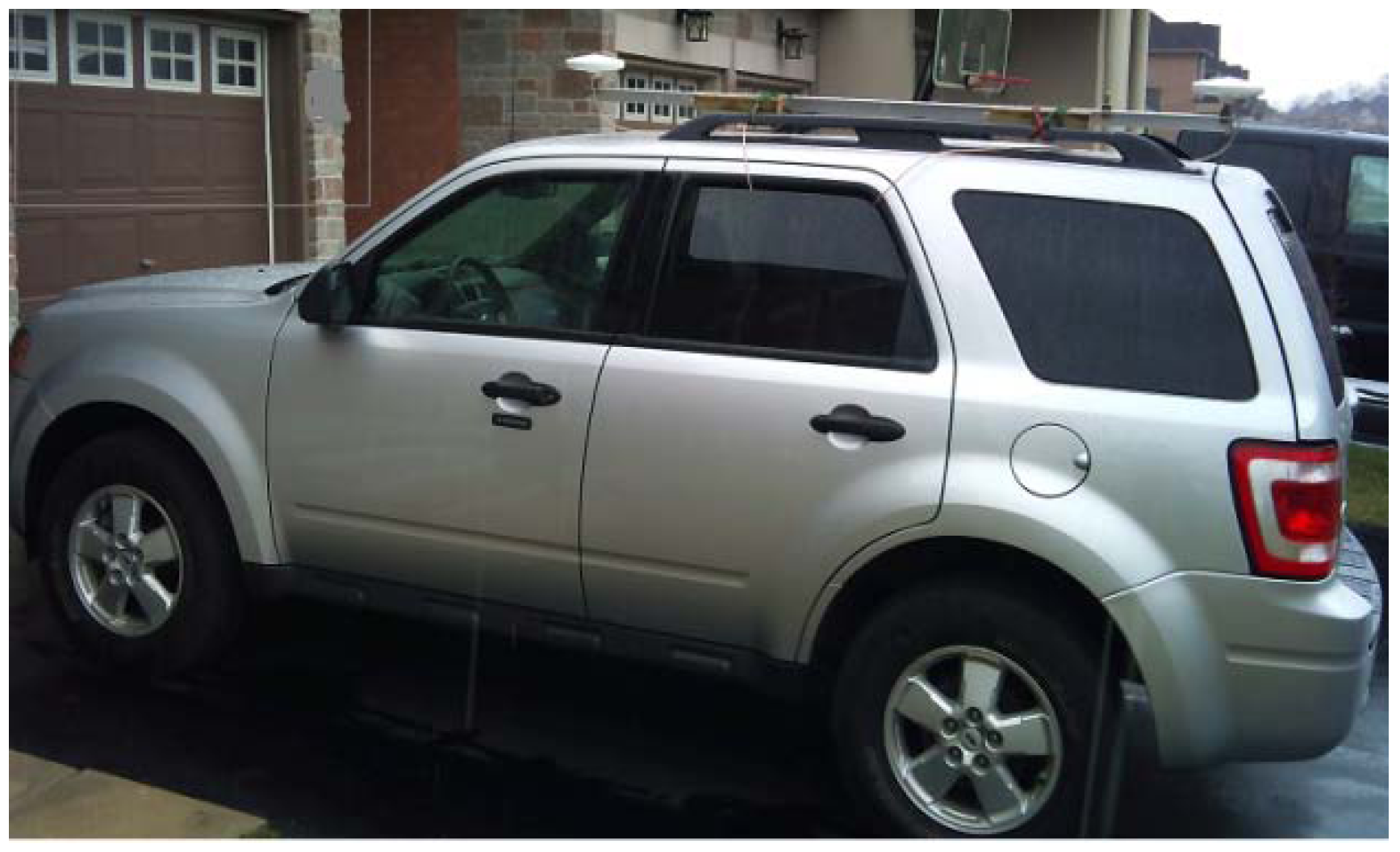
With the development of the low-cost GPS-aided inertial navigation system at York’s EOL laboratory, a number of road tests have been performed. The results from two latest road tests with Crossbow IMU400CA and IMU800CA respectively are presented in this section. One Leica GPS1200 receiver located at the start location was configured as the static base station. Another two NovAtel OEM GPS receivers, an OEM4 in the front as primary and an OEM3 in behind as secondary, were rigidly bound to one metal bar on the vehicle roof (
Figure 6) while the IMU unit was placed on the top of the console box between the driver seat and the passenger seat. The lever arm parameters were manually measured at an accuracy of ±0.5 cm.
The trajectory was designed to avoid bridges and narrow road sections to minimize the possible GPS signal blockages. The maximum baseline length was 5 km in both tests. No reverse vehicle motion occurred during the two road tests. In each road test, the vehicle first stayed stationary for 5 minutes close to the base station where more than seven GPS satellites could usually be tracked by both rover GPS receivers on the roof of the vehicle. After subsequent 30~40 minutes of driving along the selected trajectory, the vehicle returned back to the start point and remained static for 5 minutes again. The raw GPS observables including pseudo range, Doppler and carrier phase measurements were collected at 1 Hz for all GPS receivers whilst the IMU units were outputting the angular rates and the specific forces at 100 Hz. The maximum speed of the vehicle was up to 80 km/h. The specifications of two Crossbow IMU sensors used in the road tests are shown in
Table 2. In the following sections, the post-processed navigation solutions are presented because our goal is to achieve post-processed kinematic positioning and navigation solutions at an accuracy level of centimeters for the direct geo-referencing in mobile mapping.
Figure 6.
Vehicle snapshot.
Figure 6.
Vehicle snapshot.
Table 2.
IMU Specification Data.
Table 2.
IMU Specification Data.
| | | 440CA | 800CA |
|---|
| Angular Rate | Bias Stability [deg/hour] | <10.0 | <3.0 |
| | Angle Random Walk [deg/sqrt(hour)] | < 4.5 | <0.1 |
| Acceleration | Bias Stability[mg] | <1.0 | <1.0 |
| | Velocity Random Walk [m/s/sqrt(hour)] | <1.0 | <0.5 |
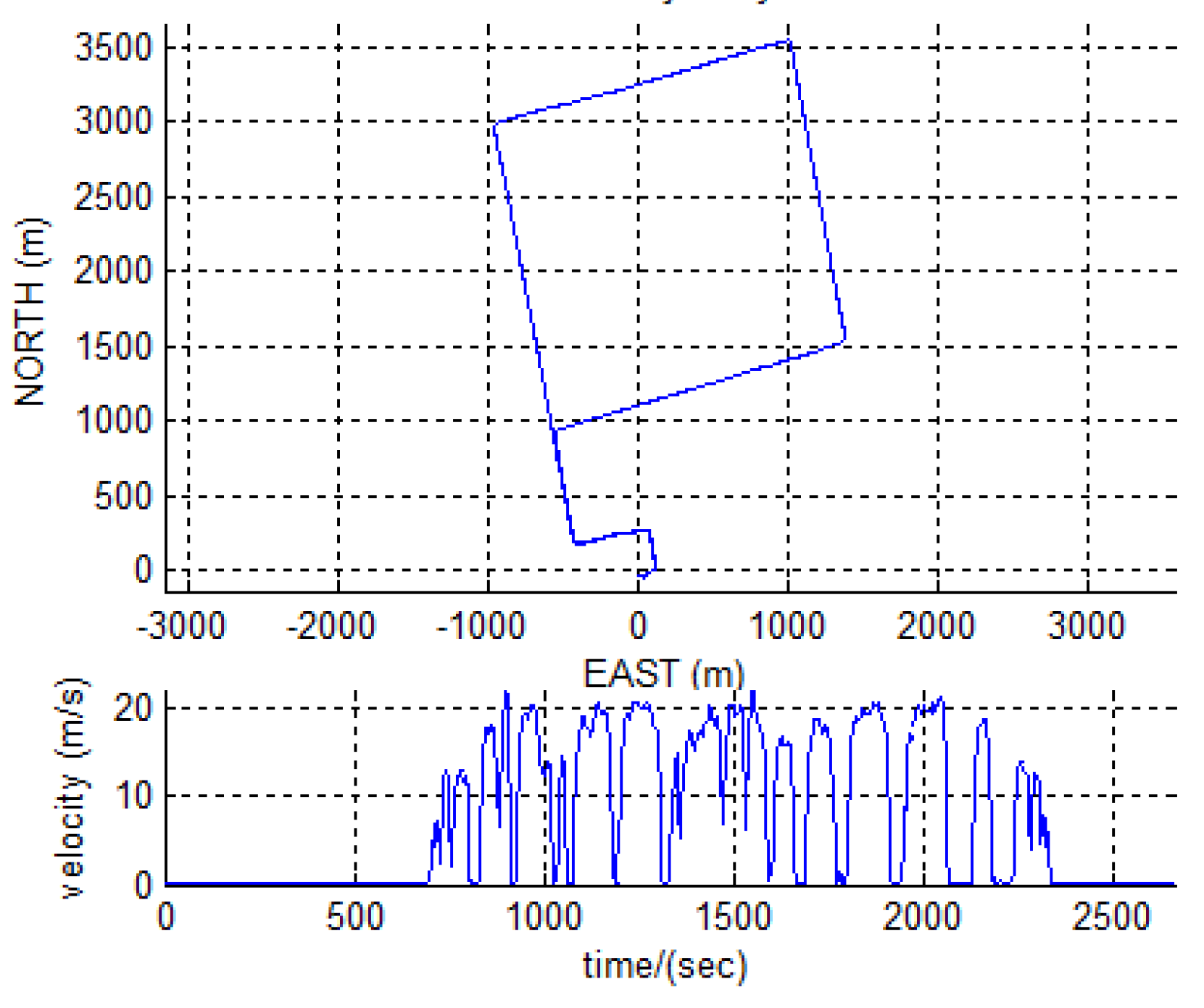
6.2. Solutions with IMU440CA
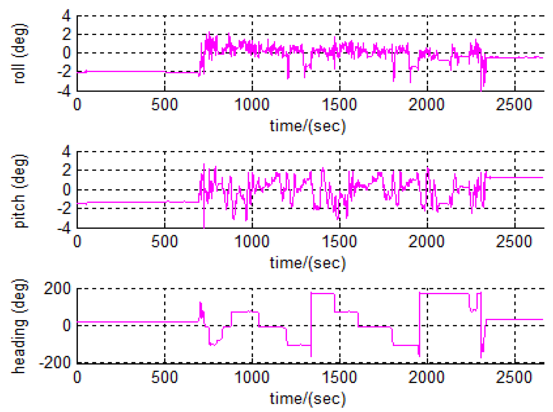
The 2D top view of the vehicle trajectory and the velocity profile are given in
Figure 7. The attitude (roll, pitch and heading) profiles are presented in
Figure 8.
Figure 7.
IMU position and velocity profiles.
Figure 7.
IMU position and velocity profiles.
Figure 8.
Attitude profiles.
Figure 8.
Attitude profiles.
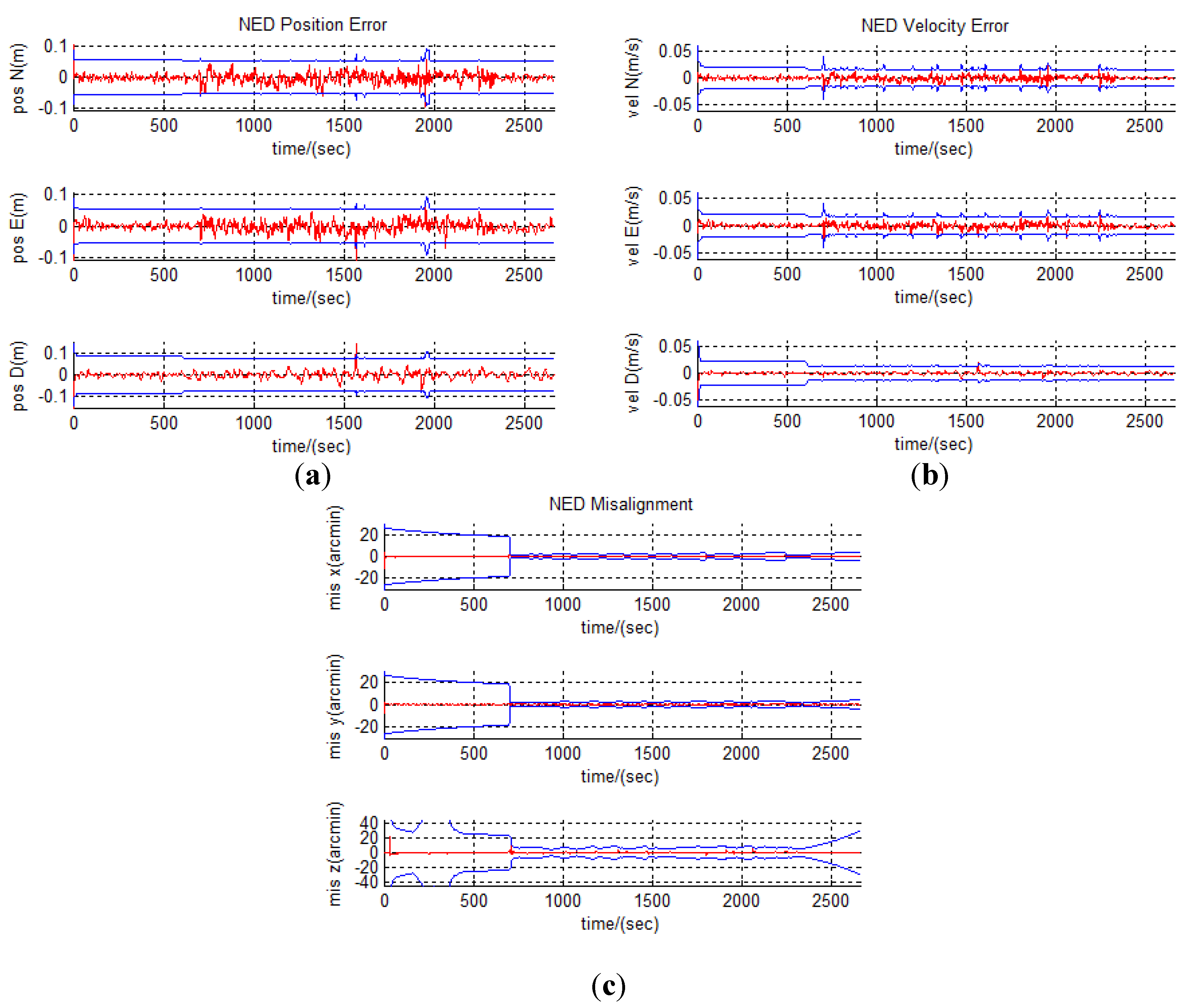
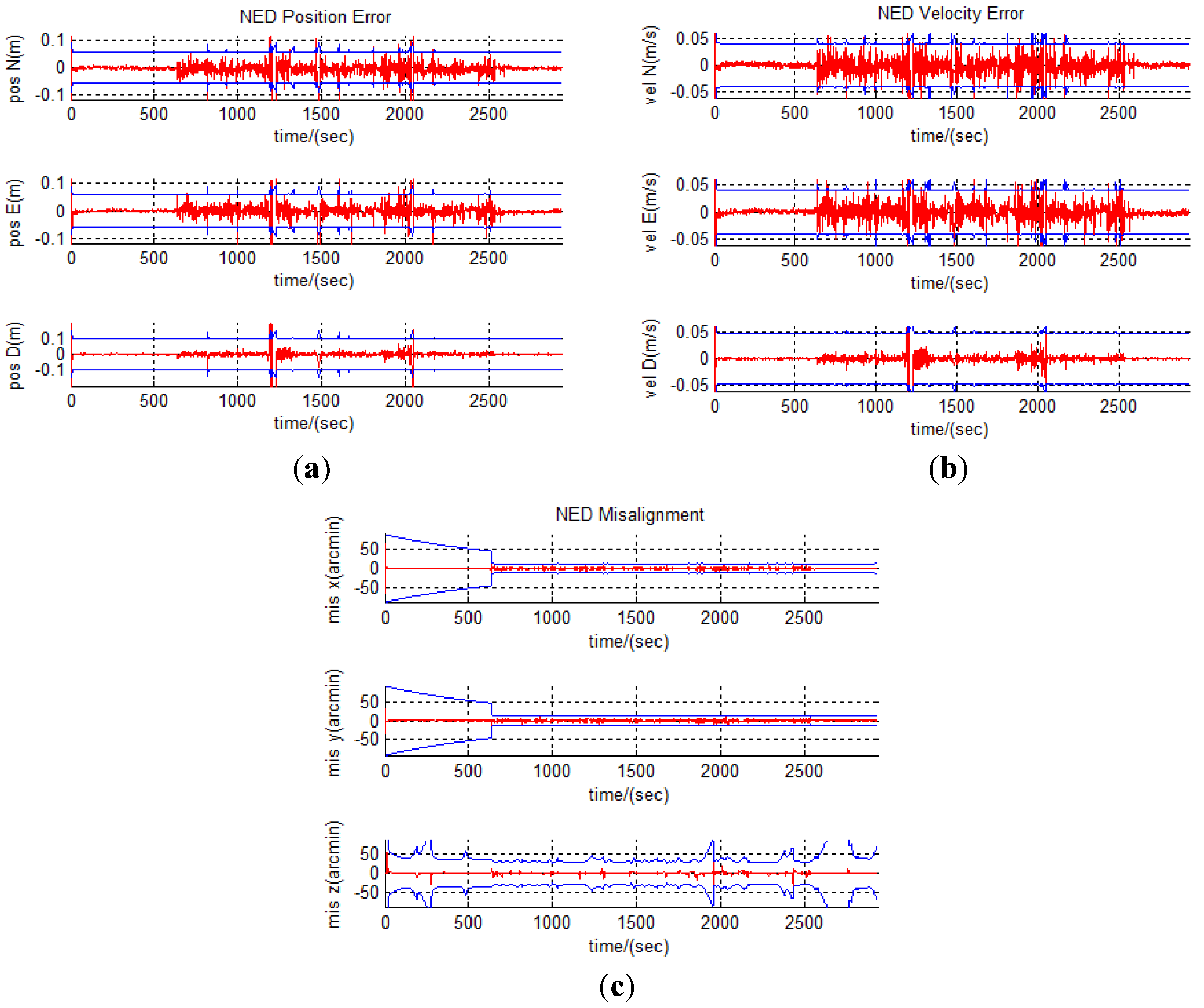
As shown in
Figure 9(a), the loosely coupled GPS-aided inertial integration reduces the inertial position error down to 2~3 cm. The two biggest spikes in
Figure 9(a,b) are due to the sub-meter accuracy of the C/A differential GPS solution during the GPS carrier phase data gap. With the aid of DGPS heading solution, the heading solution in the integration reaches an accuracy of 0.5 degree for most of the time (
Figure 9(c)).
Figure 9.
The estimated error states with IMU440CA (3-sigma envelope accuracy in blue). (a) Position Errors. (b) Velocity Errors. (c) Attitude Errors.
Figure 9.
The estimated error states with IMU440CA (3-sigma envelope accuracy in blue). (a) Position Errors. (b) Velocity Errors. (c) Attitude Errors.
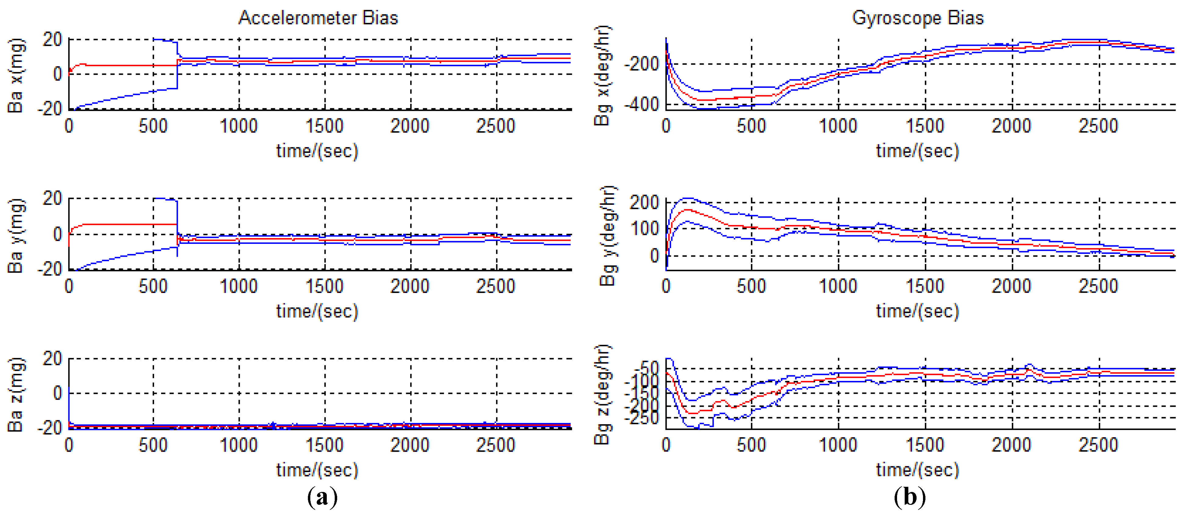
Furthermore, the IMU bias estimates are presented in
Figure 10(a,b). The IMU sensor bias on accelerometer and gyroscope measurements is modeled as the first order Gauss-Markov process. The correlation time constants and standard deviations of the driving noises are determined by tuning the results from lab calibration.
Figure 10.
The estimated IMU biases with IMU440CA (3-sigma envelope accuracy in blue). (a) Accelerometer Biases. (b) Gyroscope Biases.
Figure 10.
The estimated IMU biases with IMU440CA (3-sigma envelope accuracy in blue). (a) Accelerometer Biases. (b) Gyroscope Biases.
6.3. Solutions with IMU800CA
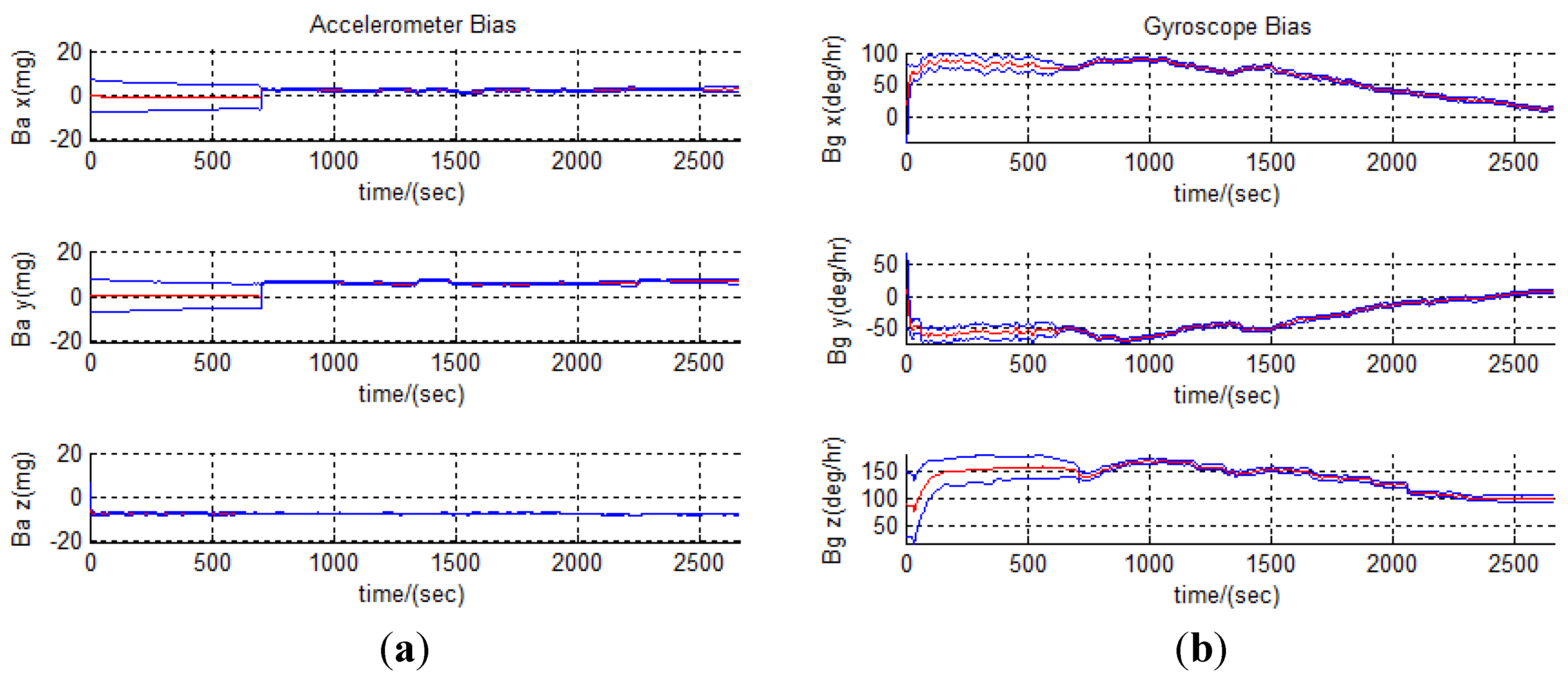
For the second road test, the trajectory and all system configurations remained as in the previous road test except for the replacement of the IMU440CA sensor by an IMU800CA sensor. In order to avoid duplication of similar plots as from the previous test, only fifteen error states are presented in
Figure 11 and
Figure 12, from which the smaller amplitudes of the error states can be observed because of the superiority of IMU800CA over IMU440CA.
Figure 11.
The estimated error states with IMU800CA (3-sigma envelope accuracy in blue). (a) Position Errors. (b) Velocity Errors. (c) Attitude Errors.
Figure 11.
The estimated error states with IMU800CA (3-sigma envelope accuracy in blue). (a) Position Errors. (b) Velocity Errors. (c) Attitude Errors.
Figure 12.
The IMU biases with IMU800CA (3-sigma envelope accuracy in blue). (a) Accelerometer Biases. (b) Gyroscope Biases.
Figure 12.
The IMU biases with IMU800CA (3-sigma envelope accuracy in blue). (a) Accelerometer Biases. (b) Gyroscope Biases.
6.4. Solution Summary
The accuracies of the position, velocity and attitude solutions are quantitatively summarized in
Table 3 through their mean, standard deviation (STD) and root-mean-square (RMS) based on their error estimates. As a result, the accuracies of the solutions can be observed from the “STD” column in
Table 3.
Table 3.
Statistics for error states in loosely-coupled GPS/IMU Kalman filter.
Table 3.
Statistics for error states in loosely-coupled GPS/IMU Kalman filter.
| | IMU440 | IMU800 |
|---|
| | mean | STD | RMS | mean | STD | RMS |
| Pos.North (m) | −0.004 | 0.070 | 0.070 | −0.003 | 0.014 | 0.014 |
| Pos. East (m) | −0.002 | 0.063 | 0.063 | −0.002 | 0.015 | 0.015 |
| Pos. Down (m) | −0.001 | 0.046 | 0.046 | −0.001 | 0.022 | 0.022 |
| Vel. North (m/s) | −0.001 | 0.021 | 0.021 | −0.001 | 0.004 | 0.004 |
| Vel.East (m/s) | −0.002 | 0.020 | 0.020 | 0.000 | 0.004 | 0.004 |
| Vel.Down (m/s) | 0.000 | 0.018 | 0.018 | 0.000 | 0.003 | 0.003 |
| Mis. x (arcmin) | 0.174 | 2.500 | 2.505 | 0.013 | 0.353 | 0.353 |
| Mis.y (arcmin) | 0.054 | 1.991 | 1.991 | −0.016 | 0.255 | 0.255 |
| Mis.z (arcmin) | −0.073 | 2.240 | 2.241 | 0.023 | 0.712 | 0.712 |
7. Conclusions
Aiming at building a low cost real-time kinematic positioning and navigation system with Linux/RTAI for the purpose of direct geo-referencing of mobile mapping sensors, a GPS-aided inertial navigation system using loosely coupled architecture was successfully developed at the York’s EOL. In addition, the LXRT service was validated in order to simplify the development of the Linux/RTAI system. For the time synchronization of the data from multiple sensors, GPS time was imported into the system with the aid of the PPS pulse and the PPS message from the NovAtel GPS unit because of its high accuracy and convenient accessibility. The results from the road tests further confirmed the success of our multisensor kinematic positioning and navigation system with Linux/RTAI. As the road tests demonstrated, the developed system could provide 3D position solutions with 5 cm accuracy and attitude solutions with 0.5 degree accuracy. In conclusion, Linux/RTAI is a suitable and economic alternative as a hard real-time operating system for multisensor integrated navigation systems in terms of hard real-time performance, degree of development difficulty, hardware compatibilities and system expenses.


