Review

Advances in Finger and Partial Hand Prosthetic Mechanisms

1
Department of Mechanics, Mathematics and Management, Politecnico di Bari, via Orabona 4, 70126 Bari, Italy
2
BionIT Labs Company, Via Cracovia 1, 73010 Soleto, Italy
*
Author to whom correspondence should be addressed.
Robotics 2020, 9(4), 80; https://doi.org/10.3390/robotics9040080
Submission received: 25 August 2020 / Revised: 28 September 2020 / Accepted: 29 September 2020 / Published: 1 October 2020
(This article belongs to the Special Issue Feature Papers 2020)

Abstract

:
Approximately 70% of the upper extremity amputations refers to partial hand loss with the involvement of one or more fingers. Historically, this type of limb amputation has been addressed adopting simple opposition designs that use the movement of the residual digit for grasping against a fixed device. Nevertheless, in the last few years, technological advances, and the introduction of modern computer-aided tools for the synthesis and functional design of mechanisms have led to the development of smaller, more robust systems that are constantly improving body-powered and electrically-powered prototypes. This paper surveys cutting-edge solutions proposed in research or available on the market for single finger or partial hand prostheses. First, the main design requirements are outlined. Then, a wide number of prototypes are detailed underlying advantages and drawbacks. The overall goal is to create a solid starting point for the study and development of the next generation of prostheses that can be developed to advance the current state-of-the-art.

1. Introduction

The development of a prosthetic finger or partial hand must necessarily have as its foundation the anatomical study of the human counterpart allowing the complete recovery of the natural functions of the latter’s residual limb. The complexity of the hand, and consequently of the fingers, lies in the compactness and small size that it presents in front of a high dexterity, through which numerous grasping modes are allowed. These features are implemented by the human hand with tendons that transmit the motion generated by remote muscles, located in the forearm, to the various joints of the finger phalanges, as explained in more detail in Section 2. Whereas many recent reviews have been presented that refer to the design of complete robotic hands [1,2,3,4] and grasping research trends [5,6], to the best of the authors’ knowledge a survey devoted specifically to the mechanisms used for finger and partial hand prosthetic or rehabilitation has not been presented in the literature. Various cutting-edge solutions that use both in body-powered and extracorporeal energy prostheses will be surveyed: the objective is to generate a solid knowledge base about the multitude of existing systems detailing advantages and disadvantages. It represents the starting point for the study and development of all prosthetic solutions that can be developed to advance the current state-of-the-art. To this aim, mechanisms derived from full prosthetic hands and that can be of interest for single finger implementations are also listed.
In this research, the existing devices have been broadly classified in three categories: one-degree of freedom (dof) mechanisms (described in Section 3), two-dofs mechanisms with one degree of underactuation (Section 4), and multi-dofs mechanisms (Section 5). Section 6 describes miscellaneous solutions. Finally, relevant conclusions and indications for future trends are drawn in Section 7.

2. Technical Requirement Definition and Analysis

The key point for a good system design is to identify well what are the customer’s problems and requests, and the technical requirements with which to fulfill them. Accordingly, a review of the artificial fingers proposed in the academic and research field or already-available on the market is necessary. Through an in-depth reading of patents and research articles, the criteria for evaluating the performance of the mechanisms underlying the finger and partial hand prostheses have been obtained. They can be divided into functional, grasp and physical characteristics.

2.1. Functional Characteristics

There are three major types of bones in the hand [7,8] including: phalanges, metacarpal and carpal bones. Numerous muscles, ligaments, tendons, and sheaths can be found within the hand. The muscles are the structures that can contract, allowing movement of the bones in the hand. The ligaments are fibrous tissues that help bind together the joints in the hand. The sheaths are tubular structures that surround part of the fingers. The tendons connect muscles in the arm or hand to the bone to allow movement. In addition, there are arteries, veins and nerves within the hand that provide blood flow and sensation to the hand and fingers. The high dexterity of the hand and fingers is implemented through tendons that transmit the motion generated by remote muscles, located in the forearm, to the various joints of the finger phalanges (Figure 1). The fibrous sheaths hold tendons in position and close to the bones.
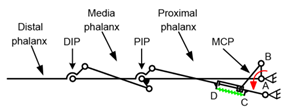
Setting aside medical/anatomical aspects that can be found in many dedicated references, e.g., [9,10] and in the pursue of an engineering functional scheme, each of the hand fingers can be seen as composed of three phalanges, except for the thumb which has two but in addition it shows a more complex mobility solution thanks to the two dofs of the trapeziometacarpal joint. All the digits are connected to the metacarpals by five MCP (metacarpophalangeal) joints. What previously said results in a model of hand that features twenty-one degrees of freedom (dofs), without the six dofs needed to position and orientate the hand in the reference system, three of which in the wrist, since the following exposition will focus on the fingers.
Amputation of a part of a hand may involve functional limitations for the amputee that are not easy to recover by orthoses or prostheses [11]. Loss of portion of hand occurs through trauma or congenital skeletal deficiencies: the former usually occurs along a straight line instead for the latter case the pattern of absence is quite variable but usually different. Patients who suffer transphalangeal amputation need no device but may desire cosmetic fingers; thumb amputation can be recovered with prosthetic thumb; distal transmetacarpal amputee search both cosmetic hands and functional devices same as proximal metacarpal amputation patients. The conventional approach to designing anthropomorphic prosthesis often involves mechanizing biological parts. This method inevitably introduces undesirable discrepancies between the human and robotic hands. The larger the level of finger amputation, the higher the extent of dexterity loss.
During manual activities, fingers are typically used to push, pull, and manipulate objects. The finger force is demonstrated to vary in a range of 30 to 110 N, respectively, from the little finger to the thumb capable of exerting the maximum force [12]. In fact, it can be estimated that the relative contribution of each finger to the total four finger force was approximately 41% (index), 32% (second), 20% (third) and 7% (fourth). In addition, a simple qualitative analysis of the hand structure reveals that the fingers are all different length and widths [13]. In addition, there is not an equal distribution of surface area on each finger and this may affect the contact stress, and subsequent force contributions of each digit.

2.2. Grasp Characteristics

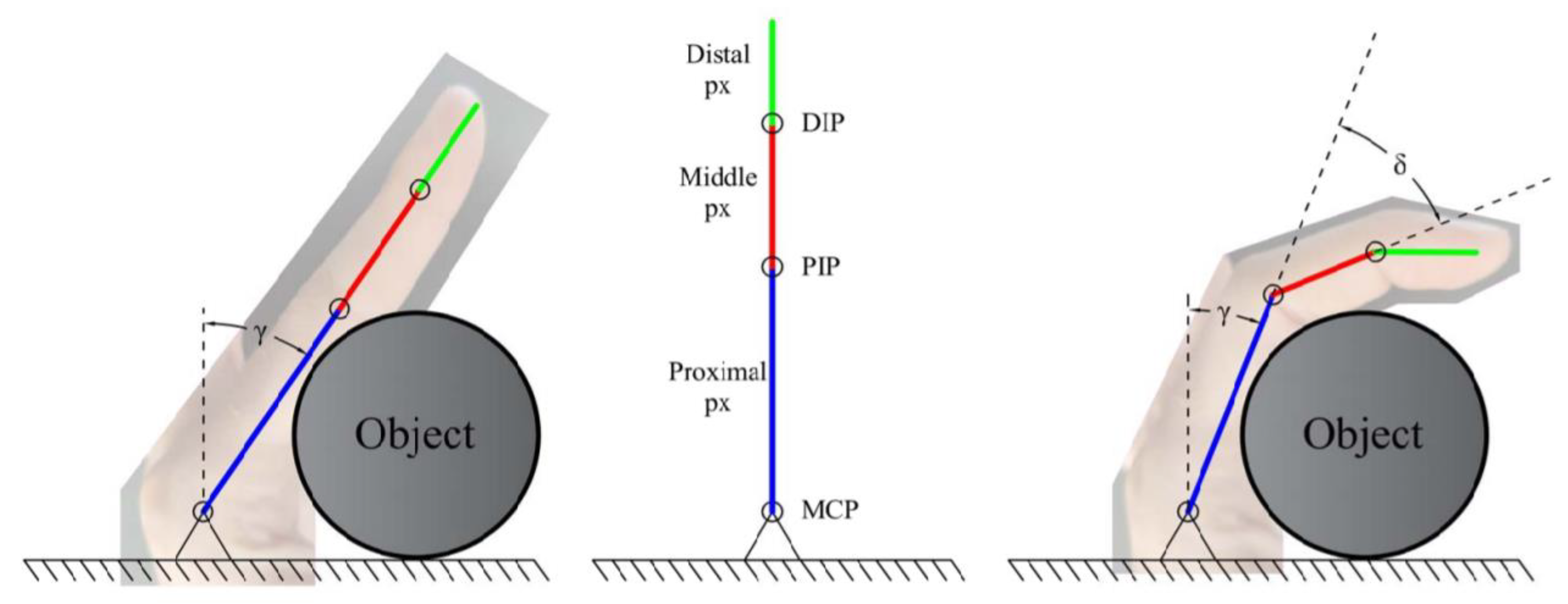
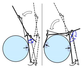
  • Natural motion: the prosthesis must emulate the closure as much as possible than an anthropomorphic hand. This ability is referred to as pre-shaping of the finger when contacting with an object (Figure 2).
  • Shape-adaptivity: the stability of each grasp pattern greatly depends on this characteristic that is often obtained with an underactuated mechanism.
  • Pinching motion: the distal phalanx remains straight or rotates in counterclockwise direction; so, the fingertips of index and thumb are in front of each other. It results in an efficient grasp for thin objects like keys or papers (Figure 3).
  • Stability: objects need to be grasped and manipulated safely with different shapes and surfaces without failures, avoiding the ejection phenomenon (i.e., negative contact forces).
  • Force isotropy: grasping should be fulfilled with a uniform distribution of forces, which allows for example a light and stable grip of fragile objects. It is a significant feature for the prosthetic finger mechanisms that adapt to the shape of the object’s body.
  • Workspace: it depends on the number and length of the phalanges with which the prosthetic finger is modeled. Most prostheses show a planar movement.
  • Stiffness: it is the relationship between the actuation torque and the phalanx movement considering the forces exerted by the object.
  • Bond and adjustment (for body-powered devices): the residual finger must be wrapped effectively by the prosthesis and be able to drive the prosthetic finger as a natural extension with an efficiency ratio as close as possible to the unit.
  • Accuracy in the required tasks.
  • Time of extension and bend motion.

2.3. Physical Characteristics

  • Weight: the lighter the better.
  • Number of phalanges: it results from a trade-off between the increase in the number of components making up the prosthesis, the improvement of the setting performance and the increase in complexity.
  • Compactness: it is defined as the ratio between the width and length of a finger. It is ideal to achieve a ratio like human finger.
  • Design flexibility: it is recommended versatility to the uniqueness of the user (finger size, size of components making up the prosthesis).
  • Biocompatible materials that avoid irritation due to prolonged use.
  • Appearance: the amputation of the upper extremities involves a change in the external appearance that can lead to psychological problems in the acceptance of one’s condition.
  • Manufacturing process: it provides a prosthesis with the best values of the above parameters at the most competitive cost considering the various production processes.
  • Noisiness: the purpose of all prosthesis is to provide the functional result without attracting undue attention to the user.

3. One-Dof Mechanisms

Most of the existing prosthetic fingers belong to the category of one-degree of freedom mechanisms, whose different embodiments are collected in Table 1 and following tables. They generally rely on a single or cascades of four-bar linkages, and consequently one general drawback is that the movement of the whole finger stops if one of the phalanxes meets the surface of an object. In other words, the one-dof mechanisms are hardly shape-adaptive.
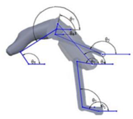
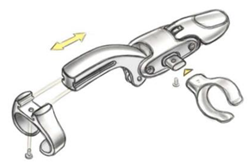
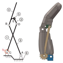
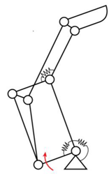
The first considered solution is shared by two devices proposed independently by [14], that is shown in the first row of Table 1, and [15]. The proposed four-bar comprises two crossing rockers connected to the ends of a rod, which allows the distal phalanx, represented by a segment with a fixed angle respect to the rod, to rotate. The prosthetic finger developed by Yeong-Jin Choi [16] uses as well a four-bar linkage (FBL), and it takes advantage of the natural finger’s movement next to it. The proximal ring serves as the anchoring point to the stump, while the middle ring drives the cross four bar linkage.
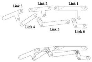
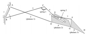
The Toronto Bloorview MacMillan (TBM) model has been developed by [17] and it is shown in the second row of Table 1. It consists of two coupled four-bar linkages with 3 phalanges, 6 links, 9 joints. Components 1, 2 and 3 embody the 3 phalanges, whereas link 4, 5 and 6 are connecting elements, which provide a natural motion to the prosthesis. The mechanism is implemented for each finger of the TBM Hand which uses a single motor to actuate all digits.
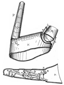
About the work [18] that traces back to the end of 1900, the stub is placed in the socket B (refer to the second row of Table 1). By bringing it towards the palm, the rock-shaft D raises all the levers H, I and K. They actuate the ratchet L which in turn lifts the lever G and allows the second phalanx to rotate relative to the first one. As the second joint is flexed, it operates the lever O obtaining the bending motion of the third joint. The aim of dog N is to lock the finger in any desired position until released by further movement of D.
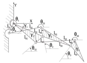
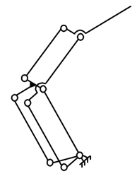
The coupling of two four-bar linkages has been also discussed in [19,20] using 3 phalanges, 5 links and 7 joints. About the finger [19], a first iteration of a five-fingered hand 3D printed prototype was developed. A slightly more complex embodiment [21] has been proposed that features 3 phalanges, 20 links, 28 joints as shown in the third row of Table 1.
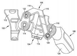
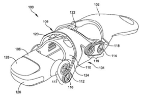
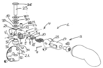
More recent and advanced finger mechanisms have been proposed by Thompson’s research team through a portfolio of significant patents that are collected in the focused Table 2. The first solution [22] is reported in the first row of Table 2 showing a four-bar linkage with 2 phalanges, 4 components, and 4 joints. This prosthesis is aimed at subjects with fingers that do not present the distal interphalangeal joint (DIP) articulation. This prosthesis is therefore named Proximal InterPhalangeal (PIP) driver. The proximal ring 112 is configured to be anchored onto the proximal phalanx. It also presents a thinner version with only 3 elements and two cage rings to retain the distal and proximal area of the PIP articulation. The residual part of the finger is wrapped and protected by the prosthesis that develops externally. Note in this regard the H-shaped rocker 108. The latter can assume any shape and configuration to better adapt to the needs of the user. In fact, there is a patent of the same inventors [23], which uses instead a Y-shaped rocker (not shown in Table 2) aimed to reduce the overall bulk of the prosthesis, gaining in compactness, slenderness and weight, but it shows the drawback of a lesser versatility with respect to the size of the user’s residual finger (solution adopted only for users with a relatively short intermediate phalanx or a limited residual part). In both patents, the proximal 112 and the intermediate 104 components are designed with a circular section for retaining the finger but they do not fit very well in some cases. The verification procedure requires the insertion of shims to reduce the aforementioned gaps and prevent blurring and/or relative movements between the finger and prosthesis.
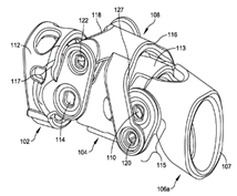
A PIP driver prototype [24] has been also proposed, as showed in the first row of Table 2, with therapeutic and/or protective aim for individuals, who have suffered an injury or any type of inhibited articulation functionality to a finger segment with a very limited amputation or no amputation at all; it ends with an opening 107 and allows the end of the digit to come out. For a feeling of greater safety, the assembly is provided with the coupling tip 106b (not shown here) with a hollow recess 123, suitable for accommodating the residual part of the finger and avoiding further injuries and hypersensitivity. To avoid hyperextension, the prosthesis may be outfitted with hard-stops (an example is the Y-shaped rocker 127).
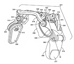
A third more sophisticated prototype shows the connection of two inverse four-bar linkage [25]: the proximal one consisting of two symmetrical rockers 318 and the tendon ring 328, and a “suspended” one that is interposed between the latter and the distal part 316 with a proximal coupler 356 and a rocker 358 passing through it. The links between the various elements and the hinged connections are proposed below to make the images more explanatory:
310 (frame) → 324 → 318 (proximal rocker) → 322 → 356 → 360 → 316
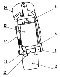
Thompson et al. [26] have presented also a similar embodiment of MCP driver prosthesis for the thumb. It has an anchor plate 102 that can be positioned above and adjacent the MCP joint by means of a hand strap on the user’s palm to ensure the proper position of the prosthesis. The hand strap and anchor plate are essential for the most important finger of the hand, responsible for the success of any grasp. Quoting John Napier [27] “a hand without a thumb is at worst nothing but an animated spatula and at best a pair of forceps whose points don’t meet properly”. In the same patent, reference is made to a second simpler and less cumbersome or invasive prototype of the MCP driver type, composed of one less element (therefore 3). The extreme distal part of the prosthesis is fixed and can only be configured with secondary procedures and by tightening the screw 220. In common with the previously reported versions, however, the distal ring 222, which must concentrically receive and retain the user’s residual thumb, can be moved longitudinally along the slot 224 to accommodate the user dimensions.
Most of Thompson’s patents are implemented with a pad in the lower part of the distal component, which has a texture in silicone or other material to mimic the natural soft touch and provide a better grip. In some cases, it is possible to install a touch screen mechanism that allows the user to interact with capacitive touch screens which react to the body’s natural electrical current.
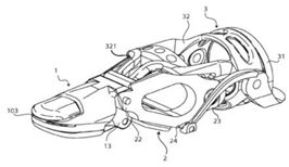
Besides Naked Prosthetics’ solutions, other thump prostheses have been proposed, as shown in Table 3. The PIP driver prosthetic thumb [28], showed in the first row of Table 3, includes 4 components coupled by hinged connections forming an inverse four-bar linkage with one dof. The substantial differences from the previous solutions are the proximal element 3 and the addition of a cable 9 designed to give a more realistic curling motion.
Cable 9 starts from element 32 and reaches to the lower surface of the distal tip helping the flexion. The inventor suggests the use of the patent as a brace by removing the wishbone-rocker 321, or as an orthopedic implant. For the other fingers, the corresponding PIP driver is presented [26], along with the MCP driver version (not shown here) comprising the driving component coupled through a ring element to the anchoring system elements.
Patent BPFF (bio-mechanical prosthetic full finger) [29] comprises the MCP driver full finger prosthesis consisting of 2 four-bar linkages. The proximal phalanges and the yoke element, which drive the middle phalanges and make prosthesis to flex are added to the original mechanism. A thumb strap connects the articulation component to the anchoring system. For more details, the reader is referred directly to the figures in [29].
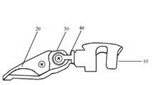
Developed by Hunter et al. [30], the drawing shown in the second row of Table 3 is fairly self-explanatory: a motor 26 causes rotation of a screw and moves longitudinally to the proximal element 24, along the slot 42, the screw nut boss 22 (hinge 21) forcing to flex the distal body 38 around the hinge 36. In addition, in this case, a simple inverse four-bar system is used.
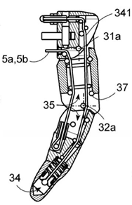
Section of the prototype [31], which does not entirely show the joint lock 218, which can be activated manually, to switch from the flexing mode of the finger to that of gripping by means of the pincer system constituting the distal component 202.
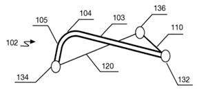
The novelty introduced by Akhtar et al. [32] (third row) is to use a three-bar system and to exploit the bending stiffness of element 104 as a third joint. A reduction of the mechanical hysteresis, greater compactness and weight reduction is obtained especially by using a single body 100. This innovative PIP joint achieves, besides the above-mentioned advantages, less energy dissipation by friction in the hinges, better ease in manufacturing process of the single pieces and no need for lubrication.

4. Two-Dofs Mechanisms with One Degree of Under-Actuation

A mechanism is referred to as underactuated if it uses fewer actuators than the actual number of dofs. The traditional actuators are replaced in these cases by passive elements including springs or mechanical limits that, by definition, cannot be controlled but having small size and high simplicity lead to a substantial reduction in the number of degrees of freedom and therefore the number of actuators [33,34]. The underactuated joint of most of the proposed prostheses corresponds to the DIP joint [35].
In the Southampton finger [36] (first row of Table 4), underactuation is implemented only for the second phalanx through a wiffle-tree mechanism. The body has 3 components, 5 links and 9 joints. The fingers of the Southampton Hand have been linked via the whiffle-tree equalizing mechanism too. The finger of the TUAT (Tokyo University of Agriculture and Technology) Karlsruhe hand [37] has 3 phalanges, 6 elements and no relative rotation before contact with the object. Bar A pulls plate D and rotates the entire finger until the proximal phalanx reaches the surface of the body to be grasped. At that point, plate D moves independently while the middle part is moved by rod B, then the four-bar managed by rod C will allow a better grip. Based on this mechanism, the inventors constructed an experimental model of the humanoid hand.
Developed by G. Puchhammer et al. [38], a prosthetic finger is presented composed by three phalanges and actuated by one motor. Inside the proximal member 10, there is a motor which through the gears and a transmission clutch drives the spindle nut 85 mounted on the recirculating ball spindle 80. The balancing arm 90 is fixed onto 85 and provides recesses 95 for levers 91 and 93. The spring 94 is the passive element that generates underactuation in the event that the intermediate member 20 (not shown) encounters an obstacle, and its rotation is stopped; as soon as the elastic torsional resistance threshold is exceeded, the spring deforms and the balance arm 90 rotates allowing the distal member 30 to flex, and correspondingly a more stable grasp. The invention [39] comprises three main segments and a linear electric motor 132. The latter drives the slider case 40 implicating rods 42 and 43 to activate the overall mechanism with regards to the pre-tightening force due to the springs inside 40 and anchored to one side with the previous rods. Rod 43 is hinged connected to a second segment and makes it rotate, while rod 42 makes third tip segment follow same movement by means of the second trace 32, which is pivotally coupled with pin 22. Thanks to the presence of passive elements (the springs), if an object hampers the second segment, the rotation is not stopped, and the additional force applied by the linear motor allows the third segment to wrap around the object. Second and third segment, rods 31 and 32 create a four-bar linkage.
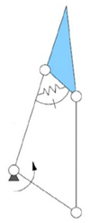
Embodiment of only two phalanges with a single four-bar has been proposed in the SARAH (self-adapting robotic auxiliary hand) prototype [40]: it has two dofs and only one actuator indicated by the circular arrow, thus a spring is installed and keeps the finger stretched until the first phalanx does not come into contact with an object. At that moment, the spring is extended allowing the relative rotation of the two phalanges. The first aim was to develop a hand for space applications.
LISA (linkage indirectly self-adaptive under-actuated) [41] has a linear spring that keeps the sliding block 4 in position. Under the pressure of the object, the plate 4 slides causing the distal 3 to rotate around joint axis 2. There are four components making up the system that represents two phalanges. This mechanism together with [40] does not provide a natural motion of the phalanges before the contact with the body. The LISA Hand has 5 fingers, 14 joint DOFs and only 5 motors: the thumb has two joints, and each of the other four fingers has three joints.
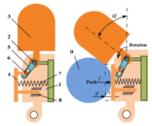
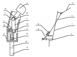
The prototype [42] is a two-joint prosthesis capable to adapt to different shape objects. When the output shaft of the motor 11 rotates, it makes the screw rod nut 51 to push linearly rod 5. Because of the spring 9, the components 9 and 6 seem to be fixed together so they rotate for a certain angle. The motion of rod 5 causes the second finger segment 4 to rotate around the joint axis 31. When an object hampers first finger segment 3, the linear translation of the screw nut, and by means of it, the rod 5 can continue its driving effect. Even in this case, the underactuation is activated by the deformation of a spring (component 9 in this case).
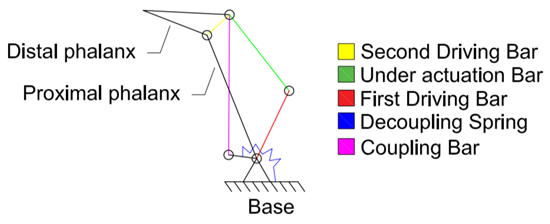
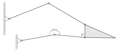
The first row of Table 5 shows the coupled and self-adaptive (COSA) finger [43]. It is obtained from the combination of two consolidated rod systems: a rigid coupled linkage and a self-adaptive underactuated linkage with the spring at the bottom. The first driving bar pushes the entire rigid system to rotate, but when it approaches the object, the shape-adaptive function is activated. Embodiment comprises two phalanges and 6 links: two more than [40] but ensuring a more natural movement. The two-phalanx prototype developed by Stavenuiter et al. [44] shows a ternary system of rods at the base in addition to [43] in order to change the level of adaptability of the mechanism. It reaches that by means of adjusting the compliance, based on rotational stiffness of the input ternary links. The derived grasper can increase its robustness against external force perturbations. The UnderActuated UA finger [45] presented in the second row of Table 5 uses as the driving input the mechanical torque applied to link 1 (it does not have the interchangeability that characterizes the patent [43]). A and B are the MCP and PIP joints and once the link 3 is in contact with the object, the torsion spring 5 allows under actuation to be activated (in this case BE and ED are collinear). A hand prototype with only three fingers is proposed and analyzed.
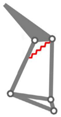
With reference to the next row of Table 5, prostheses that take advantages of adaptive bar linkage as the main element for underactuation are collected. Developed by Cheng et al. the artificial finger [46] is composed by 3 phalanges and 8 components. It results in a two-dof (MCP and PIP joints) model with passive DIP joint. Rod AB transmits the torque so the adaptive four-bar has a zero offset CD (spring with zero deformation) as long as the proximal phalanx does not come into contact. With the proximal phalanx blocked, the torque successively involves a translation of C, an extension of the spring, and a rotation of the middle phalanx. The invention [47] is an FBL (10–13) body-powered prosthesis. It uses the natural driving motion of an intact finger that wears the components 3–7. The most interesting element in this solution is the elastic link 12, whose elongation allows the prosthesis to follow the curling motion of the natural finger even if ring 3 is hindered by an object.
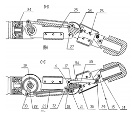
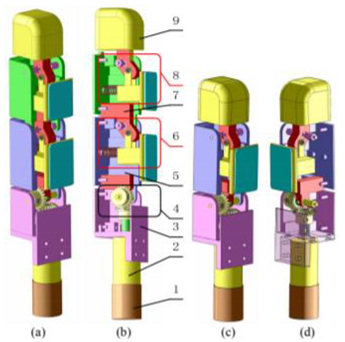
The adaptive finger [48] has been developed by Yang et al., and it is a combination of the prostheses [40,43] featuring 3 phalanges and 6 links. It performs a curling motion similar to the one of finger [37]. The driving motion of the fingers [49] is achieved by two four-bar linkages and a torque motor with bevel gear transmission. The first one is composed by the base joint torque sensor 22, the proximal knuckle link 23, the middle joint shaft 17 and the proximal knuckle 25. Therefore, when link 23 is moved forward, the remaining two segments rotate. By means of the cross four-bar linkage, made up of middle joint shaft 17, a coupling link 28, a fingertip 14 and a middle knuckle plate 26, the third segment rotates relative to second one.
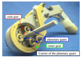
Next, solutions using gears and/or belts are considered in Table 6 that are usually adopted to provide precise grasp and transmission ratio at the cost of increased bulk volume. The finger developed by Koganezawa [50] is reported in the first row of Table 6. The mechanism is composed of the DPGS (double planetary gear system) and the compound closed linkage system assembled to form the three phalanges of the underactuated finger. The shaft of solar gear transmits the rotation torque. The other elements are the inner gear and the 3 planetary gears integrated in the carrier that keeps them at a fixed angular distance. A spring system counteracts the carrier of the planetary gears to sustain the weight of the finger and refrain the carrier from rotation under no external force loading (a). The clock-wise rotation of the solar gear gives rise to the counter clock-wise rotation of the inner gear, coupled to link 1, via the rotation of the planetary gears about their axes. Once the motion of the link 1 is hampered by an object, further clock-wise rotation of the solar gears give rise to the orbital rotation of the planetary gears around the solar gear along with the rotation of the carrier. Thus, link 2 is pushed forward causing link 4 and 5 to wrap around the object.
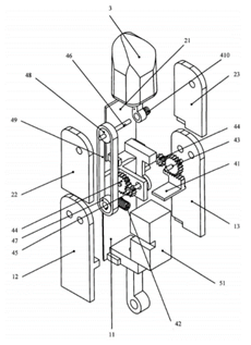
The patent [51] (last row of Table 6) is an underactuated finger prosthesis. It mainly comprises racks, gears, pinions, belts, and torsional springs. The prosthetic prototype is started when the active slider 51 inside first segment 11 comes into contact with an object: the rack 41 drives the gear 43. The spring 410 reacts in case the second segment 21 is obstructed, and further driving force given by belt 49 allows curling motion of the third segment 3. The spring 42 may be incorporated only if one wants a prosthesis that returns in the starting position after the interaction with an object.

5. Multi-Dof Under-Actuated Mechanisms

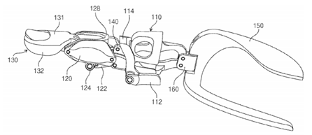
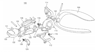
Some of the prototypes in this category are obtained simply by adding other elements to the two-dofs mechanisms described in previous Section 4. These devices are collected in Table 7 and the following tables. The first row shows the only MCP driver prosthesis, as proposed by the patent [52], which has three phalanges with three dofs based on an underactuated mechanism that allows a natural flexion of the prosthesis before coming into contact with the object, and it is finally implemented by the residual part of the user’s finger (body-powered). The system consists of two five-bar mechanisms and a four-bar linkage: the main elements are (upper figure) the proximal phalanx 110, the middle phalanx 120 and the distal 130 connected directly or indirectly through the auxiliary bracket 140, which is the centerpiece of the prosthesis. The underactuation is carried out with two pairs of torsion springs 116 and 126, which join the ends of proximal phalanx links 112–114 and middle phalanx links 122–124. Completing the entire body, 100 is the third middle phalanx link 128, which assists the rotation of the PIP and DIP joints and the connection bracket 160. The latter connects the palm fixing part 150 and it allows adduction and abduction.
The natural movement of flexion and extension is ensured by both the connecting pins and the angles between the two pairs of links 112–114 and 122–124 (marked by the two arches), which are limited by the spring elements so that two dashed virtual links are formed. When the system comes in contact with an object, first, the proximal bar 112 and, then, the middle one 122 counteract the opposite forces of the body M, resulting in an increase of the aforementioned angles; an extension of the virtual links are extended, and, consequently, a relative rotation of the auxiliary bracket 140 is obtained, enabling a shape-adaptive grasping. The same patent describes a robotic version (lower part of Table 7) implemented with an electric motor that promotes the translation of point A along the x-axis. The system is composed of a stacked four-bar linkage, a connecting rod-crank transmission mechanism, three phalanges, three dofs, and as many as twenty elements involved.
The finger architecture derived from the LISA hand [41] has 3 phalanges, 3 dofs, 7 links and no natural movement before contact (first row, Table 8). It corresponds to the modular version of the mechanism previously encountered. On the left, the index, whereas on the right the thumb with two phalanges SARAH hand’s finger [40] has 3 phalanges, 3 dofs, 7 links forming two underactuated four-bar linkages and no natural movement before contact. Underactuated fingers are not efficient for precise grasping of objects with different shapes, while one tries to have the distal phalanx parallel to the others. A system that achieves this purpose is proposed alongside by combining two parallelograms in series, and moving on a parallel plane respect to the shape-adaptive mechanism. Two springs at the tip and at the bottom are used to allow the transition to the shape-adaptive grip. Developed by Azlan et al. [53], the proposed prototype has 3 phalanges, 3 dofs, two underactuated four-bar linkage implemented and 15 elements. It is a design oriented to develop a precision grip as well as shape-adaptive. The mechanism is based on that of SARAH [40]. Activation of the micromotor causes the distal phalanx pin to slide along the slot from point C to point B, and correspondingly a counterclockwise rotation of both the proximal and intermediate phalanges. The underactuated grasp capable of adapting to the shape of the object is achieved by keeping the pin in point C. In all cases, the torque is transmitted to link 2.
The fourth row of Table 8 shows the finger solution developed by Mu et al. [54]. It results in 3 phalanges, 3 dofs, 10 rods prototype assembled with parallelogram connection. It is the only finger in this category where all degrees of freedom are implemented and it is included in this report for completeness.
The model developed by Tae-Uk et al. [55] is showed in fifth row. It is a compound of 3 phalanges, 4 dofs, two underactuated four-bar linkages and a five-bar system with spherical joints resulting in a total of 11 elements. It does not perform natural movement before contact. It is mainly based on the mechanism SARAH showed in second row of Table 8, and it allows abduction and adduction movements. A similar model is described in [56] where a 3 dofs grasper is developed with articulated active rollers at the fingertips, which provide steerable active surfaces. This allows unbounded rotation of a grasped object without the need for finger gaiting.
The last row of Table 8 shows the Ca.U.M.Ha (Cassino-underactuated-multifinger-hand) [57] finger. It has 3 phalanges, 3 dofs, two underactuated four-bar linkages coupled with a slider-crank mechanism; the model results in 7 elements and no natural movement before contact. It is also based on the prototype SARAH [40] and it differs from the latter exclusively for the connecting rod-crank system. According to the proposed mechatronic finger design, a prototype robotic hand has been built.
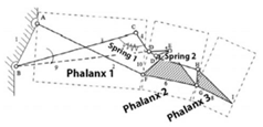
A modified LARM hand [58] is proposed in the first row of Table 9. It results in 3 phalanxes, 3 dofs, two underactuated four-bar linkages with connecting rod-crank system and 6 components. Two springs, one torsional and the other linear, ensure fixed angles as long as the prosthesis does not come into contact with an object. When phalanx 1 is hampered by an object, torque on link 3 allows the rotation of the phalanx 2, until it stops. The actuation force now is distributed onto the sliding element 5, which involves the motion of phalanx 3.
Another mechanism modeled on that used in [20] is the one developed by Li et al. [59] that presents 3 phalanges, 3 dofs, two underactuated four-bar linkages and 8 elements. It differs, with respect to that of Licheng et al. [58], for the adoption of a torsional spring.
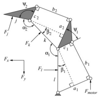
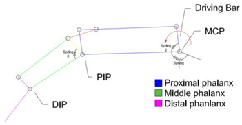
The second row of Table 9 shows the finger developed by Gopura et al. [60]: 3 phalanges, 3 dofs and two underactuated four-bar linkage with 9 elements and 3 torsional springs. The underactuation is calibrated by the different elastic constants of the finger springs (e.g., for the index 6:4:10:1). The driving torque is applied to the driving bar. Upon compression of the first spring which increases its resistance and hampers rotation of the proximal phalanx, as soon as the torsional resistance threshold of spring 2 is exceeded, the intermediate phalanx performs a relative rotation with respect to the proximal one. Once even the intermediate one is prevented by the object, compression of the third spring (with an elastic constant lower than the first two) will cause the rotation of the distal phalanx.
In the third row of Table 9 the models developed, respectively, by Hirano et al. [61] and D. Zhao [62] are shown. The first one, derived from a hand grasper, has 3 phalanges, 3 dofs, two underactuated four-bar linkages with 7 components. Furthermore, it does not perform natural movement before contact with an object if the mechanism does not include the spring 0. It has a partial similarity with the SARAH mechanism [40].
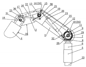
The second prosthesis [62] is a three joints version of the previously described prototype COSA [43]. It has an underactuated mechanism similar to that used by Y. Choi e D. Yoon for their prosthetic finger [52]. The driving bar is 11, the rest of the working motion is self-explanatory. Developed by Khakpour H. e L. Birglen, the prosthesis [63] has 3 phalanges, 3 dofs, rod transmission with 5 elements and no natural movement before contact. Finally, the embodiment proposed in [64] describes a underactuated human-like finger capable of multi-mode under-actuated grasping function. The switch element is the telescopic link 24–26 between one mode and the other. If component 24 is locked, the rotation of the large bevel gear 7 causes the near knuckle 2, middle knuckle 3, and far knuckle 4 to rotate as a whole entity. When an object hampers the motion, the underactuation mechanism is enabled by passive elements that are the torsional springs on the rotation hinges 9, 13 and 18.
If the locking mechanism 26 is activated, the motion of finger resembles an anthropomorphic rotation and facilitates the wrapping of the envelope of the object. This prosthesis presents the adaptive bar of [46,47], coupled with torsional springs for each joint as [61,62].

6. Miscellaneous Mechanisms

In this section, prostheses that do not fall in the previous categories are discussed. The first example (first row of Table 10) is the VINCENT System active patent [65] with a motor which allows rotation of one four-bar linkage finger. Distal bend is obtained by the spring bar connections 8. The VINCET passive patent [66] is showed as well to the right. It comprises one or two passive joints which rotate around the 4′ axis.
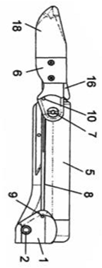
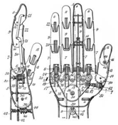
The second row collects passive prosthesis ([67,68]): the flexion is done by assistance of another hand or any rigid surface. In one embodiment of [68], the interlocking mechanism in the joint 30 comprises a rebounded type progressive hinge lock; when the bending angle exceeds 90-degree, it rebounds and returns smoothly to starting point. The overall embodiment (full hand TBM) [69] proposed in the third row of Table 10 take advantage from the sprockets and coupling worm gears engaging each other. The picture is already self-explanatory: upon turning of worm 25 in one direction or the other, the first finger section will be turned either into its open or closed position. That happens because of lever 20, which is pivotally mounted to the worm-gear 24 by means of pin 18 and translates lengthwise.
The thumb mechanism is obtained in the same way, but it presents a differential bevel gear system 62, which engages worm-gear thumb thanks to a conical friction face 54 and spring 57. Chain-belt 35 passes around the main sprocket wheel 24 that drives all fingers by means of the differential mechanism.
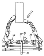
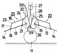
The embodiment developed by Guongling G. et al. [70] is a three-finger hand able to conform to the different shape of objects being handled with only one drive motor. Shape adaptation is gained through the pivotal connection of the central plate actuator 40 to the drive arm 58. The curling motion of each finger is obtained by coupled gears whose motion is driven by arm 32 by means of the gear wheel 42 at its end. The last model of the third row of Table 10 is a mechanical hand [71] that comprises two finger elements 13 and 14. It may grip an object 11 only if the rods 28 of the actuator 27 are driven downwardly. Consequently, the rods 25 are diverged and the mechanical fingers can pivotally turn around the joints 15 making the forward ends 14 move. The latter collide into a table top so while the rods 28 are further driven downwardly, the movements of elements 14 are hampered and the closed link mechanisms 20 begin to modify their shape allowing the forward ends of the second finger elements 14 to overcome the table top and eventually grip the object 11. Even if the object 11 is positioned in a concavity, the current mechanism can grasp it.
Adequate treatment was not reserved for the cable driven systems collected in the last row of Table 10 ([72,73,74,75,76,77,78,79,80,81,82]), mostly dedicated to full hand devices, since they mostly speculate on the method of implementation than describing a real challenge for a new synthesized mechanism. The main problem from which the various solutions were born is the routing scheme inside the prosthetic finger. Notable examples of tendon-driven mechanisms for anthropomorphic robotic fingers can be found in [83], where the equivalent actuator and tendon arrangement of the human lumbrical (LU) muscle is achieved, and in [84], which implements tendon sheaths that work as a series of elastic pulleys to help efficiently transmit flexion forces from the muscles to the joints.

7. Discussion and Conclusions

The essential aspects drawn from the described prototypes have been reported in the previous sections, highlighting their advantages and disadvantages in the projection of the future generation prostheses to be developed. The summary Table 11, Table 12, Table 13 and Table 14 provide at-a-glance view for the four categories used in this review. In all tables, the second column highlights the type of actuation if externally powered (EP) or body-powered (BP), providing information, where appropriate, about the driving joint (MCPd, PIPd). The third column reports each type and number of assembled mechanisms (C-FBL: coupled four-Bar linkage; U-FBL: underactuated four-bar linkage), whereas the fourth column counts how many phalanges and links/components are mated in the assembly. The next two are check columns where SA stands for shape-adaptive and NM for natural motion; both are useful evaluation criteria adopted for the survey. The seventh and eighth columns lists the pros and cos of each solution. The last part of the table is adopted for further notes.
As highlighted throughout this paper, the hand is a very important limb for the human being, its ability and dexterity that allow the individual to carry out most of the daily activities severely penalizes those who have amputations. The refusal to use some of the prostheses already available on the market derives from the failure to align to the customer’s needs the requirements offered by the product in terms of functionality, aesthetic recovery, weight, and cost.
All prosthetic fingers described in this survey can be further categorized based on the specific actuation mechanism that can take advantage on: either body-powered or externally powered energy. The former inevitably include additional elements required to: wrap the residual part of the finger, be as comfortable as possible, and guarantee their connection in a stable way (for example the circular shims used in [22,23,24,25,26] may be not efficient enough) sacrificing the compactness of the device and the aesthetic-psychological impact that this could entail. Rigid body mechanisms are often used, in body-powered prosthesis with their multitude of feasible configurations and integrations (for example with cables as in [28,29]), allowing the transmission of larger grasping forces and a back-drivable characteristic. On the contrary, the externally powered prostheses tend to use elements that are more similar to human nature like cables for the transmission. In this way, they obtain a considerable gain in the volume of space occupied by the prosthesis but produce lower forces and introduce significant elasticity and friction. Both issues have an impact on the transmission efficiency and the theoretical-physical modeling of the system.
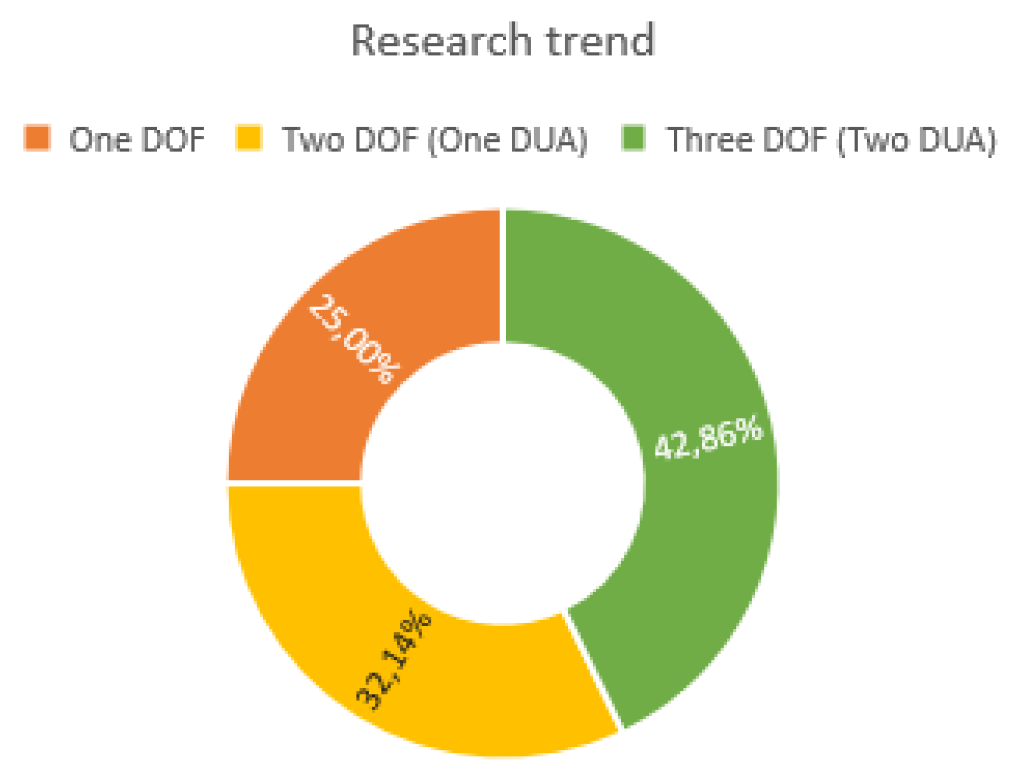
In an attempt to create a simpler, more compact and lighter prosthesis that imitates the appearance and natural movement of the fingers, many researchers have tried to reduce the dofs taking advantage of the potential of the underactuated differential mechanisms. It is in this direction that researchers have been moving in the past twenty years as the plots in Figure 4 and Figure 5 testify.
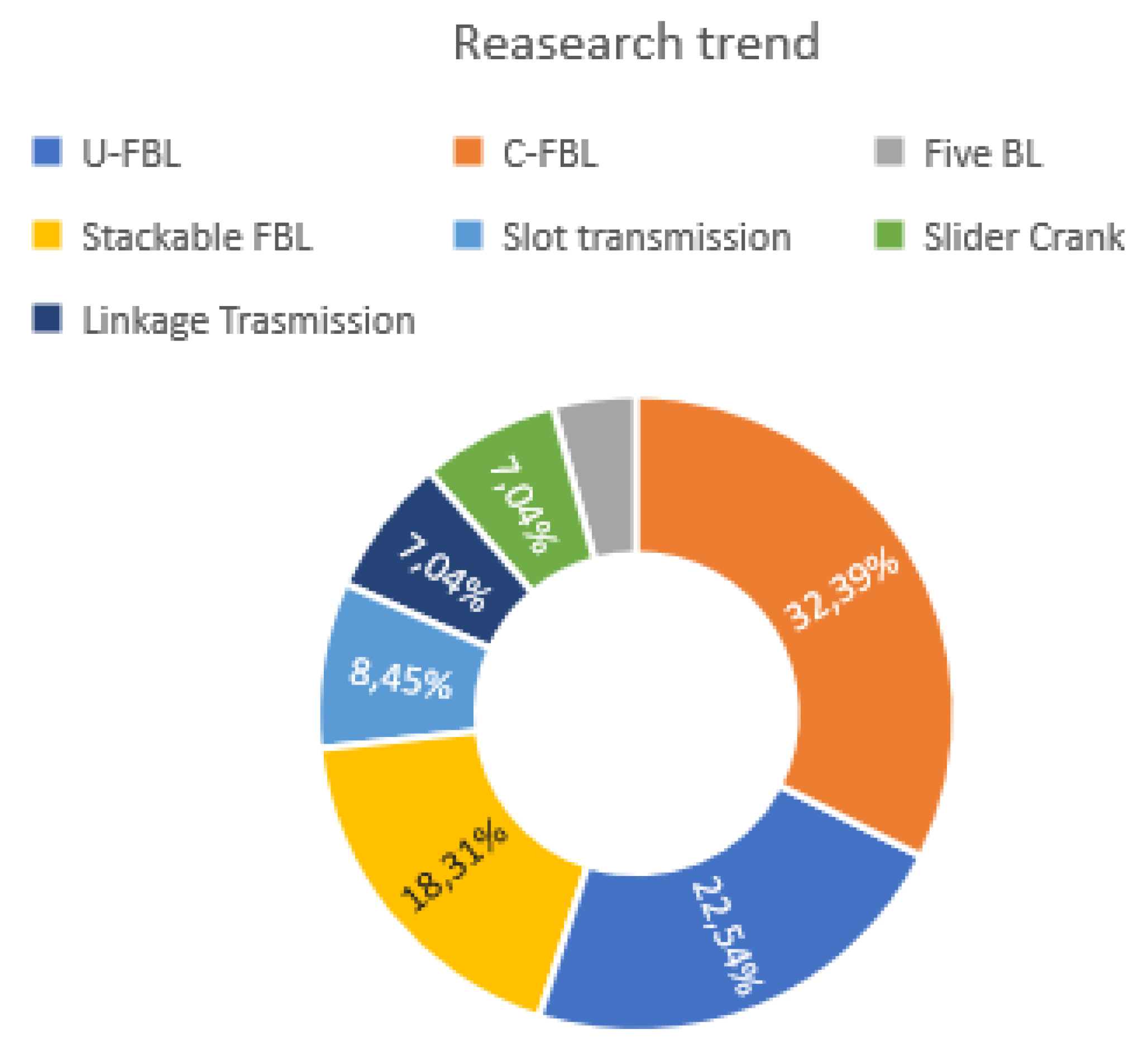
The latest research trend is to adopt a two/three-phalange device with a single controlled movement, whereas the other degrees of motion are underactuated; furthermore the tendency (Figure 5) reveals the use of multiple mechanisms, stacked and integrated with springs and hard stops so as to create different grasping configurations, and rehabilitate the amputated part.
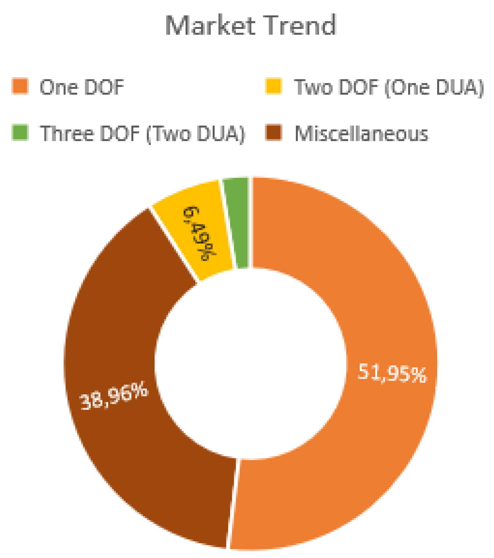
It is worth mentioning that Figure 4 and Figure 5 do not consider explicitly the users who have suffered from partial finger amputation. Therefore, research trends may not fully reflect the real market needs. In this respect, only about 15% of the research prostheses have turned into a market product and adopted by medical operators, and among them the most adopted solution is that using one-dof and underactuation (Figure 6). By collecting the impressions from interviewed clinicians and medical operators, the main issues that ready-to-market solutions need to fulfill are: functionality that is preferred by users over cosmetics, readily available and easily replaceable spare parts, lightness and robustness, and the customization in response to the uniqueness of the user finger.
In general, increasing the degrees of freedom usually leads to fingers that are shape-adaptive but also leads to an absence of natural movement. However, there are prostheses that integrate both abilities, although testing and data collection have proved them commercially inappropriate. It is also clear that as the components making up the prosthesis increase, and so the complexity, the ease in making stable and functional grips decreases as well [41].
Regarding the addition of elastic elements, mechanical limit stops, and guiding slots, the superiority of the latter against the introduction of undesired physical phenomena such as non-linearities and permanent deformations of the former is undoubted, which ensures as well less maintenance and/or repair and/or replacement.
It should be noted that the driver mechanism, which allows the finger motion, should preferably be on the upper side of the phalanges. This is to avoid any mechanical interference between the object under grasp and the mechanism [57].
Finally, in some patents (for example those presented in Table 2) simpler, lighter, less bulky secondary models are available featuring a smaller number of elements and lower costs. However, they are less protective, less robust, asymmetrical, and eccentric in some cases, and they certainly do not introduce an aesthetical improvement (e.g., double ring that allows actuation with the help of adjacent healthy fingers [16,25]).
One of the main advantages of the body-powered prostheses, which must be preserved in future models, is the high versatility to the size of the customer’s fingers and to the degree of disability, e.g., the type of actuation has been referred to as MCP or PIP driver to indicate the presence of the corresponding joint in the residual part of the finger.
In conclusion, future research should be devoted to develop new body-powered prototypes that can outperform existing state-of-the-art solutions. One notable example is that developed by Y. Choi e D. Yoon [52], showed in the first row of Table 7, that is the only one-dof body-powered prosthesis, which ensures both a natural motion and a shape-adaptive grasp thanks to its underactuated mechanism. However, the patent results in a bulky, asymmetrical solution, and it is not suitable for manipulate fragile objects. As matter of fact, the success of grasping largely depends on the bearable critical load of the torsional springs before they compress and permit curling motion.
The second prototype family of interest is that developed by Naked Prosthetics (collected in Table 2), which provides a different solution for what concerns the number of digits, price, drive joint, aesthetic appearance, and anchoring. They are not as complex as the one strengthened by Y. Choi e D. Yoon even though they permit natural motion with a lower number of components, earning in compactness and lightness. These devices try to solve the wrap problem of residual fingers with the use of circular shims that represents a potential weakness and a field for future improvement. All Naked Prosthetics devices comprise a linkage system, tip pad for interaction with touch screens, nails for both aesthetic appearance recovery and rehabilitation of scratching and peeling functionalities.
Shape-adaptability in [52] is achieved via underactuation using springs. The set of solutions to achieve the same goal is wide. An alternative and maybe better proposition could be the use of different type of passive elements that overcome the disadvantages of springs or adopt an hybrid solution like the DPGS by Koganezawa [50] or the one by MacDuff ([28,29]) that integrate tendon-cables to improve curling motion. Furthermore, only few prototypes have implemented a precision pinching grasp ([40,53]) but all of them are externally powered.
Therefore, future prostheses will have to face the challenge to design a solution that addresses all the above-mentioned aspects.

Author Contributions

Conceptualization and Methodology, E.D., G.Z., G.M., G.R.; writing—original draft preparation, E.D., G.R.; writing—review and editing, G.Z., G.M. All authors have read and agreed to the published version of the manuscript.

Funding

The financial support of the projects: Autonomous DEcision Making in Very Long Traverses (ADE), H2020 (Grant No. 821988), and Agricultural inTeroperabiLity and Analysis System (ATLAS), H2020 (Grant No. 857125), is gratefully acknowledged.

Conflicts of Interest

The authors declare no conflict of interest.

References

  1. Neha, E.; Suhaib, M.; Mukherjee, S. Design Issues in Multi-finger RoboticHands: An Overview. In Advances in Engineering Design; Springer Nature Singapore Pte Ltd.: Delhi, India, 2019; pp. 335–343. [Google Scholar]
  2. Sarac, M.; Solazzi, M.; Frisoli, A. Design Requirements of Generic Hand Exoskeletons and Survey of Hand Exoskeletons for Rehabilitation, Assistive or Haptic Use. IEEE Trans. Haptics 2019, 1, 99. [Google Scholar] [CrossRef] [PubMed] [Green Version]
  3. Rashid, A.; Hasan, O. Wearable technologies for hand joints monitoring for rehabilitation: A survey. Microelectron. J. 2018, 88, 173–183. [Google Scholar] [CrossRef]
  4. Piazza, C.; Grioli, G.; Catalano, M.G.; Bicchi, A. A Century of Robotic Hands. Annu. Rev. Control. Robot. Auton. Syst. 2019, 2, 1–32. [Google Scholar] [CrossRef]
  5. Graña, M.; Alonso, M.; Izaguirre, A. A Panoramic Survey on Grasping Research Trends and Topics. Cybern. Syst. 2019, 50, 40–57. [Google Scholar] [CrossRef]
  6. Li, R.; Qiao, H.; Knoll, A. A Survey for Methods and Strategies for High-precision Robotic Grasping and Assembly Tasks—Some New Trends. IEEE/ASME Trans. Mechatron. 2019, 24, 2718–2732. [Google Scholar] [CrossRef]
  7. Health. Available online: https://www.hopkinsmedicine.org/health/treatment-tests-and-therapies/anatomy-of-the-hand (accessed on 30 September 2020).
  8. Getting the Finger. Available online: https://mddirect.org/tag/finger-anatomy/ (accessed on 30 September 2020).
  9. Thompson, J.C. Netters Concise Orthopaedic Anatomy, 2nd ed.; Saunders Elsevier: Philadelphia, PA, USA, 2010. [Google Scholar]
  10. Doyle, J.R. Anatomy of the finger flexor tendon sheath and pulley system. J. Hand Surg. 1988, 13, 473–484. [Google Scholar] [CrossRef]
  11. Bender, L.F.; Koch, R.D. Meeting the challenge of partial hand amputations. Ortothics Prosthet. 1976, 30, 3–11. [Google Scholar]
  12. Bretz, K.J.; Jobbagy, Á.; Bretz, K. Force measurement of hand and fingers. Biomech. Hung. 2010, 3, 61–66. [Google Scholar] [CrossRef]
  13. Buryanov, A.; Kotiuk, V. Proportions of Hand Segments. Int. J. Morphol. 2010, 28, 755–758. [Google Scholar] [CrossRef] [Green Version]
  14. Leal-Naranjo, J.A.; Torres-San Miguel, C.R.; Carbajal-Romero, M.F.; Martínez-Sáez, L. Structural numerical analysis of a three fingers prosthetic hand prototype. Int. J. Phys. Sci. 2013, 8, 526–536. [Google Scholar] [CrossRef]
  15. Imbinto, I.; Montagnani, F.; Bacchereti, M.; Cipriani, C.; Davalli, A.; Sacchetti, R.; Gruppioni, E.; Castellano, S.; Controzzi, M. The S-Finger: A Synergetic Externally Powered Digit with Tactile Sensing and Feedback. IEEE Trans. Neural Syst. Rehabil. Eng. 2018, 26, 1264–1271. [Google Scholar] [CrossRef] [PubMed]
  16. Choi, Y.-J. Finger Prosthesis. K.R. Patent 1020180096088A, 1 September 2016. [Google Scholar]
  17. Dechev, N.; Cleghorn, W.; Naumann, S. Multiple finger, passive adaptive grasp prosthetic hand. Mech. Mach. Theory 2001, 36, 1157–1173. [Google Scholar] [CrossRef]
  18. Bashore, I. Automatic Artificial Finger. U.S. Patent 319,776, 9 June 1885. [Google Scholar]
  19. Omarkulov, N.; Telegenov, K.; Zeinullin, M.; Begalinova, A.; Shintemirov, A. Design and analysis of an underactuated anthropomorphic finger for upper limb prosthetics. In Proceedings of the 2015 37th Annual International Conference of the IEEE Engineering in Medicine and Biology Society (EMBC), Milan, Italy, 25–29 August 2015; Volume 2015, pp. 2474–2477. [Google Scholar]
  20. Rodriguez, N.E.; Carbone, G.; Ceccarelli, M. Optimal Design of driving mechanism in a 1-D.O.F. anthropomorphic finger. Mech. Mach. Theory 2006, 41, 897–911. [Google Scholar] [CrossRef]
  21. Jang, G.; Lee, C.; Lee, H.; Choi, Y. Robotic index finger prosthesis using stackable double 4-BAR mechanisms. Mechatronics 2013, 23, 318–325. [Google Scholar] [CrossRef]
  22. Thompson, R.; Bengtsson, J.; Peto, A.C.; Macduff, C.C.; Minnis, S.T.; Klumper, E.D.; Crittenden, B.A. Bio-Mechanical Prosthetic Finger with H-Shape Rocker. U.S. Patent 0239068 A1, 24 August 2017. [Google Scholar]
  23. Thompson, R.; Bengtsson, J.; Peto, A.C.; Macduff, C.C.; Minnis, S.T.; Klumper, E.D.; Crittenden, B.A. Bio-Mechanical Prosthetic Finger with Y-Shape Rocker. U.S. Patent 296361 A1, 19 October 2017. [Google Scholar]
  24. Thompson, R.; Bengtsson, J.; Peto, A.C.; Macduff, C.C.; Minnis, S.T.; Klumper, E.D.; Crittenden, B.A. Biomechanical Finger Brace Assembly. U.S. Patent 0020691 A1, 26 January 2017. [Google Scholar]
  25. Thompson, R.; Bengtsson, J.; Peto, A.C.; Macduff, C.C.; Minnis, S.T.; Klumper, E.D.; Crittenden, B.A. Bidirectional Biomechanical Prosthetic Full Finger Configured for Abduction and Adduction with MCP Pivot and Multiple Finger-Ring. U.S. Patent 181870 A1, 29 June 2017. [Google Scholar]
  26. Thompson, R.; Bengtsson, J.; Peto, A.C.; Macduff, C.C.; Minnis, S.T.; Klumper, E.D.; Crittenden, B.A. Bio-Mechanical Prosthetic Thumb. W.O. Patent 035387 A1, 2 March 2017. [Google Scholar]
  27. Napier, J.; Russell, N.J.; Russell, T. Hands; Princeton University Press: Princeton, NJ, USA, 1993; Volume 55. [Google Scholar]
  28. Macduff, C.C. Bio-Mechanical Prosthetic Thumb. U.S. Patent 0303750 A1, 9 October 2014. [Google Scholar]
  29. Macduff, C.C. Bio-Mechanical Prostetic Full Finger. U.S. Patent 0303749 A1, 9 October 2014. [Google Scholar]
  30. Hunter, M.; Del Rey, M. Mechanical Finger. U.S. Patent 0235555 A1, 18 August 2016. [Google Scholar]
  31. Martinez-Luna, C.H.; Michael, A.I.D.; Taylor, R.D.; Todd, R.F.; Thane, R.H.; Craig, M.K.; Kevin, E.K.; Carlton, W.K.; Benjamin, D.P.; Todd, W.R.; et al. Prosthetic Fingertips End Effector. W.O. Patent 075031 A1, 18 April 2019. [Google Scholar]
  32. Choi, K.Y.; Akhtar, A.; Bretl, T. Compliant Four-Bar Linkage Mechanism for a Robotic Finger. U.S. Patent 0328550 A1, 31 October 2019. [Google Scholar]
  33. Massa, B.; Roccella, S.M.; Carrozza, M.C.; Dario, P. Design and development of an underactuated prosthetic hand. Mech. Sci. 2002, 1, 19–26. [Google Scholar]
  34. Zappatore, G.A.; Reina, G.; Messina, A. Analysis of a Highly Underactuated Robotic Hand. Int. J. Mech. Control 2017, 18, 17–24. [Google Scholar]
  35. Zappatore, G.A.; Reina, G.; Messina, A. A Toolbox for the Analysis of the Grasp Stability of Underactuated Fingers. Robotics 2019, 8, 26. [Google Scholar] [CrossRef] [Green Version]
  36. Kyberd, P.J.; Light, C.; Chappell, P.H.; Nightingale, J.M.; Whatley, D.; Evans, M. The design of anthropomorphic prosthetic hands: A study of the Southampton Hand. Robotica 2001, 19, 593–600. [Google Scholar] [CrossRef]
  37. Fukaya, N.; Toyama, S.; Asfour, T.; Dillman, R. Design of the TUAT/Karlsruhe Humanoid Hand. In Proceedings of the International Conference on Intelligent Robots and Systems, Takamatsu, Japan, 31 October–5 November 2000. [Google Scholar]
  38. Puchhammer, G.; Haslinger, M. Prosthetic Finger. U.S. Patent 0191343 A1, 29 July 2010. [Google Scholar]
  39. Hua, L.; Sheng, X.J.; Zhu, X.Y. Underactuated Mechanical Finger with Self-Adaption to Shapes. C.N. Patent 103786161A, 14 May 2014. [Google Scholar]
  40. Laliberté, T.; Gosselin, C. Underactuation in Space Robotic Hands. In Proceedings of the International Symposium on Artificial Intelligence and Robotics & Automation in Space, Montreal, QC, Canada, 18–22 June 2001. [Google Scholar]
  41. Li, G.; Jin, J.; Deschamps-Berger, S.; Sun, Z.; Zhang, W.; Chen, Q. Indirectly self-adaptive underactuated robot hand with block-linkage mechanisms. Int. J. Precis. Eng. Manuf. 2014, 15, 1553–1562. [Google Scholar] [CrossRef]
  42. Pan, Z.H.; Zhang, W.Z. Connection Rod Key Slot Type Coupling Under-Actuated Double-Joint Robot Finger Device. C.N. Patent 102935642A, 20 February 2013. [Google Scholar]
  43. Zhang, W.; Zhao, D.; Zhou, H.; Sun, Z.; Du, D.; Chen, Q. Two-DOF coupled and self-adaptive (COSA) finger: A novel underactuated mechanism. Int. J. Humanoid Robot. 2013, 10, 1330001. [Google Scholar] [CrossRef]
  44. Stavenuiter, R.A.; Birglen, L.; Herder, J. A planar underactuated grasper with adjustable compliance. Mech. Mach. Theory 2017, 112, 295–306. [Google Scholar] [CrossRef]
  45. Li, X.; Huang, Q.; Chen, X.; Yu, Z.; Zhu, J.; Han, J. A novel under-actuated bionic hand and its grasping stability analysis. Adv. Mech. Eng. 2017, 9. [Google Scholar] [CrossRef] [Green Version]
  46. Cheng, M.; Jiang, L.; Ni, F.; Fan, S.; Liu, Y.; Liu, H. Design of a Highly Integrated Underactuated Finger towards Prosthetic Hand. In Proceedings of the IEEE International Conference on Advanced Intelligent Mechatronics, Munich, Germany, 3–7 July 2017. [Google Scholar]
  47. Zou, H.Y.; Song, H.X.; Zhang, H.M.; Sun, J.N.; Zhang, J.R.; Sun, J.; Wang, Q.; Yuan, B. Functional Finger Prosthesis. CN104825259A, 30 April 2015. [Google Scholar]
  48. Yang, D.P.; Zhao, J.D.; Gu, Y.K.; Wang, X.Q.; Li, N.; Jiang, L.; Liu, H.; Huang, H.; Zhao, D.-W. An Anthropomorphic Robot Hand Developed Based on Underactuated Mechanism and Controlled by EMG Signals. J. Bionic Eng. 2009, 6, 255–263. [Google Scholar] [CrossRef]
  49. Huang, H.; Liu, H.; Zhao, J. Under-Actuated Coupling Transmission Type Imitation Human Finger Mechanism. C.N. Patent 101190528A, 4 June 2008. [Google Scholar]
  50. Koganezawa, K.; Kunugi, N.; Niikura, R. Backdrivable mechanism for artificial finger. IFAC Proc. Vol. 2011, 44, 8095–8100. [Google Scholar] [CrossRef] [Green Version]
  51. Tián, L.; Zhāng, W.Z.; Chén, Q.; Dōu, D.; Sūn, Z.G. Underactuated Drive Finger Device of Imitating Cascaded Connection of Hand of Robot. C.N. Patent 101049695A, 10 October 2007. [Google Scholar]
  52. Yoon, D.; Choi, Y. Adaptive Robotic Finger Prosthetis for Grasping Arbitrary Object Shape. U.S. Patent 0235782 A1, 23 August 2018. [Google Scholar]
  53. Azlan, N.; Yamaura, H. Anthropomorphic finger with optimized geometric parameters for pinching and grasping tasks. Mech. Mach. Theory 2012, 49, 52–66. [Google Scholar] [CrossRef]
  54. Mu, D.; Huang, Z. A new type of paralle finger mechanism. In Proceedings of the International Conference of Robotics and Biomimetics, Sanya, China, 15–18 December 2007. [Google Scholar]
  55. Tae-Uk, K.; Yonghwan, O. Design of spatial adaptive fingered gripper using a spherical five-bar mechanism. In Proceedings of the 2014 International Conference on Advanced Mechatronic Systems, Kumamoto, Japan, 10–12 August 2014. [Google Scholar]
  56. Yuan, S.; Epps, A.D.; Nowak, J.B.; Salisbury, J.K. Design of a Roller-Based Dexterous Hand for Object Grasping and Within-Hand Manipulation. In Proceedings of the IEEE International Conference on Robotics and Automation (ICRA), Paris, France, 31 May–4 June 2020; pp. 8870–8876. [Google Scholar]
  57. Rea, P. On the Design of Underactuated Finger Mechanisms for Robotic Hands. Adv. Mechatron. 2011, 6, 131–150. [Google Scholar]
  58. Wu, L.; Carbone, G.; Ceccarelli, M. Designing an underactuated mechanism for a 1 active DOF finger operation. Mech. Mach. Theory 2009, 44, 336–348. [Google Scholar] [CrossRef]
  59. Li, X.; Lan, T.; Wu, L. Kinematics simulation for a new kind of underactuated robotic finger. Int. J. Model. Simul. 2017, 37, 234–240. [Google Scholar] [CrossRef]
  60. Gopura, R.A.R.C.; Bandara, D.S.V.; Gunasekera, N.P.A.; Hapuarachchi, V.H.; Ariyarathna, B.S. A prosthetic hand with self-adaptive fingers. In Proceedings of the 2017 3rd International Conference on Control, Automation and Robotics (ICCAR), Nagoya, Japan, 22–24 April 2017. [Google Scholar]
  61. Hirano, D.; Nagaoka, K.; Yoshida, K. Design of underactuated hand for caging-based grasping of free-flying object. In Proceedings of the 2013 IEEE/SICE International Symposium on System Integration, Kobe, Japan, 15–17 December 2013. [Google Scholar]
  62. Zhang, W.Z.; Zhao, D.Y.; Chen, Q.; Dou, D.; Sun, Z.G. Coupling Under-Actuated Integrated Three-Joint Robot Finger Device. C.N. Patent 101722514A, 9 June 2010. [Google Scholar]
  63. Khakpour, H.; Birglen, L. Numerical Analysis of the Grasp Configuration of a Planar 3-DOF Linkage-Driven Underactuated Finger. J. Comput. Nonlinear Dyn. 2012, 8, 021010. [Google Scholar] [CrossRef] [Green Version]
  64. Deng, H.; Duan, X.G.; Zhang, Y. Multimode Under-Actuated Human Finger Simulation Device with Quick Reflex Grabbing Function. C.N. Patent 102873689A, 16 January 2013. [Google Scholar]
  65. Schulz, S. Finger Element. D.E. Patent 10 2008 056 520, 3 May 2012. [Google Scholar]
  66. Schulz, S. Finger Element with a Passive Joint. D.E. Patent 10214011554 A1, 2 November 2016. [Google Scholar]
  67. Point Design LLC. Available online: https://pointdesignsllc.com/products/prosthetic-fingers/ (accessed on 30 September 2020).
  68. Fong, T.D. Finger Prosthesis. U.S. Patent 0330432 A1, 27 December 2012. [Google Scholar]
  69. Alberto, P.; Vincent, P.; Apel, F.H. Artificial Limb. U.S. Patent 1507682, 9 September 1924. [Google Scholar]
  70. Guo, G.L.; Qian, X.K.; Gruver, W.A. Multi-Function Mechanical Hand. U.S. Patent 5378033A, 3 January 1995. [Google Scholar]
  71. Itoh, H. Mechanical hand. U.S. Patent 3927424, 21 January 1974. [Google Scholar]
  72. Jaworski, E. Humanlike Mechanical Finger for Prosthetic Hands and Massaging Device. U.S. Patent 0160873, 30 June 2011. [Google Scholar]
  73. Traverso, S.; Lince, A.; Laffranchi, M.; de Michieli, L.; Boccardo, N. An Underactuated Prosthetic Hand. W.O. Patent 215577 A1, 14 November 2019. [Google Scholar]
  74. Masahiro, I.; Hiroshi, Y. Prosthetic Finger. J.P. Patent 146998A, 20 August 2015. [Google Scholar]
  75. Akyürek, E.; Kalganova, T.; Mukhtar, M.; Paramonov, L.; Steele, L.; Simko, M.; Kavanagh, L.; Nimmo, A.; Huynh, A. Design and Development of Low Cost 3D Printed Ambidextrous Robotic Hand Driven by Pneumatic Muscles. Int. J. Eng. Tech. Res. 2014, 2, 179–188. [Google Scholar]
  76. Laliberte, T.; Baril, M.; Guay, F.; Gosselin, C. Towards the design of a prosthetic underactuated hand. Mech. Sci. 2010, 1, 19–26. [Google Scholar] [CrossRef]
  77. Baril, M.; Laliberte, T.; Gosselin, C.; Routhier, F. On the Design of a Mechanically Programmable Underactuated Anthropomorphic Prosthetic Gripper. J. Mech. Des. 2013, 135, 121008. [Google Scholar] [CrossRef]
  78. George, L.E. Artificial Finger. U.S. Patent 2867819, 13 January 1959. [Google Scholar]
  79. Carrozza, M.; Suppo, C.; Sebastiani, F.; Massa, B.; Vecchi, F.; Lazzarini, R.; Cutkosky, M.; Dario, P. The SPRING Hand: Development of a Self-Adaptive Prosthesis for Restoring Natural Grasping. Auton. Robot. 2004, 16, 125–141. [Google Scholar] [CrossRef]
  80. Partial M Finger. Available online: https://www.college-park.com/partial-m-finger (accessed on 30 September 2020).
  81. Liberating Technologies. Available online: https://liberatingtech.com/ (accessed on 30 September 2020).
  82. Massey, P.L.; Stormon, L.T. Hand and Forearm Prostheses. U.S. Patent 4291421, 29 September 1981. [Google Scholar]
  83. Shirafuji, S.; Ikemoto, S.; Hosoda, K. Development of a tendon-driven robotic finger for an anthropomorphic robotic hand. Int. J. Robot. Res. 2014, 33, 677–693. [Google Scholar] [CrossRef]
  84. Xu, Z.; Todorov, E. Design of a Highly Biomimetic Anthropomorphic Robotic Hand. In Proceedings of the IEEE International Conference on Robotics and Automation (ICRA), Stockholm, Sweden, 16–21 May 2016; pp. 3485–3492. [Google Scholar]
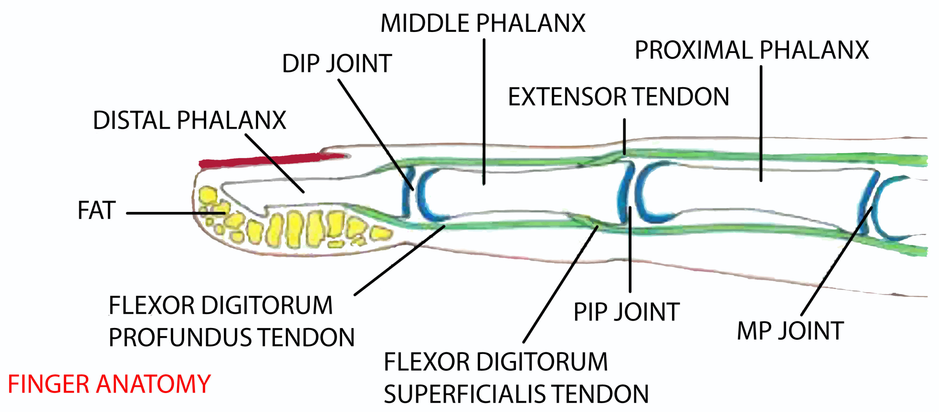
Figure 1. Finger anatomy [8].
Robotics 09 00080 g001
Figure 2. Prosthetic finger without (left) and with pre-shaping ability (right).
Robotics 09 00080 g002
Figure 3. Pinching grasp modality.
Robotics 09 00080 g003
Figure 4. Types of single finger prostheses developed in research during the last 20 years. DUA: degree of underactuation.
Robotics 09 00080 g004
Figure 5. U-FBL: underactuated four bar linkage; C-FBL: coupled-FBL; BL: bar linkage.
Robotics 09 00080 g005
Figure 6. Types of single finger prostheses available on the market.
Robotics 09 00080 g006
Table 1. Overview of one-degree of freedom (dof) actuated finger prostheses.
ReferenceMechanismNotes
[14,15,16] Robotics 09 00080 i001
[14]
Robotics 09 00080 i002
[16]
One crossed FBL
[17,18] Robotics 09 00080 i003
[17]
Robotics 09 00080 i004
[18]
Quite similar leverages
[19,20,21] Robotics 09 00080 i005
[20]
Two coupled FBL
Table 2. Patent family by Naked Prosthetics (https://www.npdevices.com/).
ReferenceMechanismNotes
[22,23,24] Robotics 09 00080 i006
[22]
Robotics 09 00080 i007
[24]
[25,26] Robotics 09 00080 i008
[25]
Robotics 09 00080 i009
[26]
Table 3. Prosthetic mechanisms designed for thumb prosthesis.
ReferenceMechanismNotes
[28,29] Robotics 09 00080 i010 Robotics 09 00080 i011
[28]
[30,31] Robotics 09 00080 i012
[30]
Robotics 09 00080 i013
[31]
Guiding slot
[32] Robotics 09 00080 i014 Robotics 09 00080 i015Three-Bar linkage
Table 4. Underactuated prostheses with 2-dof.
ReferenceMechanismNotes
[36], adapted from [37,38,39] Robotics 09 00080 i016 Robotics 09 00080 i017 Robotics 09 00080 i018 Robotics 09 00080 i019Presence of a passive rotative driving element
[36]adapted from [37] [38][39]
[40] Robotics 09 00080 i020
[41,42] Robotics 09 00080 i021 Robotics 09 00080 i022Both with linear rod and torsional spring
[41][42]
Table 5. Underactuated prostheses with 2-dof that combine more than one type of mechanisms.
Adapted from [43] Robotics 09 00080 i023
[44,45] Robotics 09 00080 i024 Robotics 09 00080 i025Passive element on coupler. One FBL
Adapted from [44][45]
Adapted from [46,47] Robotics 09 00080 i026 Robotics 09 00080 i027Adaptive bar linkage
Adapted from [46][47]
[48,49] Robotics 09 00080 i028 Robotics 09 00080 i0292 FBL: one is crossed
[48][49]
Table 6. Underactuated prostheses with 2-dof that use gears and/or belts.
[50] Robotics 09 00080 i030 Robotics 09 00080 i031
© 2020 IFAC. Reproduced with permission from IFAC-Proceedings Volumes, 44,1, pg 8097.
[51] Robotics 09 00080 i032
Table 7. Underactuated multi-dof solutions.
ReferenceMechanismNotes
[52] Robotics 09 00080 i033
Robotics 09 00080 i034
Robotics 09 00080 i035
Table 8. Underactuated multi-dof modular solutions.
[41] Robotics 09 00080 i036
[40] Robotics 09 00080 i037
[53] Robotics 09 00080 i038
Adapted from [54] Robotics 09 00080 i039
Adapted from [55] Robotics 09 00080 i040
[57] Robotics 09 00080 i041
Table 9. Underactuated multi-dof linkage solutions.
[58,59] Robotics 09 00080 i042 Robotics 09 00080 i043modified LARM hand
[58][59]
Adapted from [60] Robotics 09 00080 i044
Adapted from [61,62] Robotics 09 00080 i045 Robotics 09 00080 i046
Adapted from [61][62]
Adapted from [63] Robotics 09 00080 i047
[64] Robotics 09 00080 i048
Table 10. Miscellaneous mechanisms.
ReferenceMechanismNotes
[65,66] Robotics 09 00080 i049 Robotics 09 00080 i050
[65][66]
[67,68] Robotics 09 00080 i051 Robotics 09 00080 i052Passive prosthesis with back-drivable mechanism
[67][68]
[69,70,71] Robotics 09 00080 i053 Robotics 09 00080 i054 Robotics 09 00080 i055Under actuation from the wrist using gears and leverages
[69][70][71]
[72,73,74,75,76,77,78,79,80,81,82] Robotics 09 00080 i056 Robotics 09 00080 i057 Robotics 09 00080 i058Cable driven prosthesis
[72][73][74]
Table 11. Review at-a-glance one-dof prostheses.
IndexTypeMechanismN. Phalanges–LinksSANMProsConsNotes
One dof mechanism[14]EPOne C-FBL2–3 BasicNo High force
[15]EPOne C-FBL2–3 No back-drivable mechanism limits Force
[16]BP MCPdOne C-FBL2–4 Follow NM of finger next to it, BasicIts motion is completely dependentSimilar to [31] and [36]
[17]EPTwo C-FBL3–6 Mimic NM
[18]BP MCPdOne C-FBL3–6 Dog “N” locking systemSimilar to [41]
[19]EPTwo C-FBL3–5 Hook grasp, 3DPEasy Ejection
[20]EPTwo C-FBL3–5 Mimic NM Similar to [44]
[21]EPStackable FBL3–20 Mimic NMComplex
[22,23]BP PIPdOne C-FBL2–4 Compact, wrap around, 3DP, adaptable, slenderness (Y-shaped), hard-stopsShims, limit adaptability (Y-shaped)
[25]BPTwo C-FBL3–6 Same as [22], improved NMMore complex
[28]BP PIPdOne C-FBL2–4 Same as [22], Cable and spring hinges for improving NMSame disadvantages of Y-shaped [22]
[30]EPOne C-FBL2–3 Accurate motionWear of guiding slot
[31]EPOne C-FBL2–4 Joint lock to switch mode
[32]EPOne C-3BL2–3 Less energy dissipation, compact, lightNarrow range of adaptability due to link’s stiffness
Table 12. Review at-a-glance two-dof underactuated prostheses.
IndexTypeMechanismN. Phalanges–Links SANMProsConsNotes
One underactuated dof mechanism[36]EPTwo C-FBL3–5Light, compact, whiffle-tree SA mechanismSA between only two phalanges, no natural uncurling motion
[37]EPOne C-FBL, One multi-bar3–6Good graspSA and NM between only two phalanges
[38]EPOne U-FBL, One C-FBL, One DPGS3–7Accurate motionBulky, UA strongly depend on spring property
[39]EPOne FBL (balancing arm, slider)3–7Whiffle-tree SA mechanismSA between only two phalangesSimilar to [36], [37] and 25
[40]EPOne U-FBL2–4 Basic, lightUA strongly depends on spring property
[41]EPSliding Block2–4 Indirect UABulky
[42]EPScrew nut and a slider2–6CompactComplicated assembly: too mates in narrow spaceSimilar to [41]
[43]EPOne U-FBL, One C-FBL2–6Mimic NM, can switch drive linkSame as [40] about spring, bulky
[44]EPOne U-FBL2–4 Adjustable compliance
[45]EPOne U-FBL, One C-FBL2–4 Same as [43], unable to switch drive link, limited range of motion
[46]EPOne adaptive C-FBL, One C-FBL3–8Performs precision and power graspSame as [43], SA between only two phalanges
[47]BPOne FBL2–4Ease of useSA between only two phalangesSimilar to [46]
[48]EPOne U-FBL, One C-FBL3–6 Same as [43]
[49]BPRack, gears, belts, slider3–8 Accurate UA motionUA strongly depend on spring property, complicated assembly
[50]EPOne spingle and nut, One balancing arm3–7Accurate motionDepends on torsional spring property
[51]BPTwo C-FBL3–7Accurate motion, compactSA between only two phalangesSimilar to [48]
Table 13. Review at-a-glance multi-dof underactuated prostheses.
IndexTypeMechanismN. Phalanges–Links SANMProsConsNotes
Multi-dof mechanism[40]EPTwo U-FBL3–7 Performs precision and power grasp Modular embodiment of model [40]
[41]EPSliding Block3–7 No NMModular embodiment of model [41]
[52]BP MCPdTwo U-5BL, One C-FBL 3–9SA and NM with a BP prosthesesUnable to perform grasp of fragile object, UA depends on torsional springs properties
[53]EPTwo U-FBL and a guiding slut3–15Performs precision and power grasp Bulky, complexUse a micro-motor to switch grasp type
[54]EPParallelogram linkage3–10 All DOFs are actuated by motors
[55]EPTwo U-FBL, One spherical 5BL3–11 4 DOFs allow abduction and adductionComplex
[57]EPTwo U-FBL3–7 Highly adaptive mechBulky
[58]EPTwo U-FBL3–8Good SABulky and complexUpgraded version of LARM [20]
[59]EPTwo slider-crank FBL3–6Less bulky than [59], more ease solutionUA strongly depends on spring propertyUpgraded version of LARM [20]
[60]EPTwo U-FBL3–9 UA strongly depends on three springs properties and their compliance ratio
[61]EPTwo U-FBL3–7 UA strongly depends on three springs properties, bulkyNM conf. named caging grasp
[62]EPLinkage system3–11Mimic NM, can switch drive linkBulky, spring depending propertiesThree-joints version of [41], similar to [61]
[63]EPLinkage system3–5 Less complex and bulkyUA strongly depends on two springs propertiesSimilar to [40]
[64]EPLinkage and gear system3–10Accurate motion, NM and SA if switch element is activatedSosfisticated, no NM if switch element is locked
Table 14. Review at-a-glance miscellaneous prostheses.
IndexTypeMechanismN. Phalanges–Links SANMProsConsNotes
Miscellaneous[65,66]EPOne C-FBL2–3 Compact, basic Passive version with one or two joints
[67]BPSpring joints linkage3–3 AdaptablePassive
[68]BPInterlocking mech.1 Slenderness, compact, light, ease solutionFriction, passive
[69]EPLinkage and gears system3 Basic, ease solutionMotion comes from gears on palm
[70]EPOne FBL. Gears3Accurate motionSame as 40, easy ejection, bulkySA obtained by wrist
[71]EPLinkage system2/3–15/17Able to avoid obstaclesBulky, ease ejection
[72,73,74,75,76,77,78,79,80,81,82]BPTendon-actuated3Slenderness, compact, light, ease solutionComplex routing scheme and manufacturing process
[81]BPTendon-actuated3Slenderness, compact, light, ease solutionAesthetic not recovered