1. Introduction
Direct-contact mechanisms, such as gear and cam mechanisms, are mechanisms with higher pairs. The simplest direct-contact mechanism consists of a frame, a driving link, and a driven link, in which the driving and driven links are in contact with each other to transmit motion and force. Kinematic analysis for such a three-link direct-contact mechanism can sometimes be replaced by its equivalent four-bar linkage in order to calculate the velocity and acceleration at a particular instant [
1,
2,
3,
4,
5]. Although there might be an infinite number of equivalent four-bar linkages for a three-link direct-contact mechanism, the one with its coupler connecting the centers of curvature of the driving and driven links is referred to as the “representative equivalent four-bar linkage” [
2]. Alaci et al. [
6] applied the concept of equivalent linkage to derive the analytical expressions for the relative motion between the members of a higher pair in a planar three-link mechanism; the characteristics for the relative velocity and relative acceleration, depending on the local geometry of the pair of profiles in contact with each other can be analytically obtained by using their presented method. Some applications in the aspect of reverse engineering may also be carried out based on the theoretical development. That is, for an existing direct-contact mechanism with an unknown input-output relation, when the geometric information for the members of the existing higher pair (such as measured coordinates or curved-fitted equations of their actual profiles, and also some measured link-length related dimensions) is known, the contact points for the existing higher pair as well as their corresponding radii of curvature can be accordingly obtained. Subsequently, the kinematic analysis for the existing direct-contact mechanism can be indirectly performed through the concept of equivalent linkage without solving cumbersome equations for the higher-pair contact analysis [
7,
8,
9]. Furthermore, when the physical properties for the members of the existing higher pair (such as their masses, centers of masses, and mass moments of inertia) are known, dynamic force analysis for the existing direct-contact mechanism can also be performed, for which the indirectly obtained accelerations for the existing higher pair can be used for calculating their inertia forces and moments. Thus, the shaking forces and moments [
5] in the existing direct-contact mechanism can be evaluated.
The concept of equivalent linkage has also been adopted in some practical applications. Wu et al. [
10] propose a simplified graphical method for determining the radii of curvature of disk cam profiles, which is based on the construction of the equivalent four-bar linkage for a disk cam mechanism through Freudenstein’s third theorem. Chang and Wu [
11,
12,
13] analyze the mechanical errors in disk cam mechanisms and in planar cam-modulated linkages by transforming each cam-and-follower mechanism (or sub-mechanism) into its equivalent four-bar linkage (or sub-linkage) in order to derive the analytical equations for the positioning errors of the driven link(s). In addition, Chang and Wu [
14] and Chang et al. [
15] introduce some specially designed measuring fixtures for inspecting the profile errors of conjugate disk cams, respectively, whose principles are based on the conjugate condition analysis via the equivalent linkage of an assembled conjugate cam mechanism consisting of a pair of inspected conjugate disk cams and a measuring fixture. In these practical applications, the concept of equivalent linkage is quite helpful in developing systematic approaches.
McPhate and Daniel [
1] provided a proof to show that the equivalent four-bar linkage can give correct values of velocity and acceleration. However, the equivalent four-bar linkage cannot give a correct value of the time rate of change of acceleration, called the jerk or pulse. Such a situation is described in most textbooks for kinematics of machinery, but without giving proofs or demonstrations. Chang and Yang [
16] discussed the inequivalence of the direct-contact mechanisms and their equivalent four-bar linkages in the aspect of jerk analysis through two case studies. Their results show that the equivalent four-bar linkage indeed cannot give a correct value of jerk for most situations in the two case studies, but the major cause of the infeasibility is still not discussed in detail.
This paper aims at extending Chang and Yang’s work [
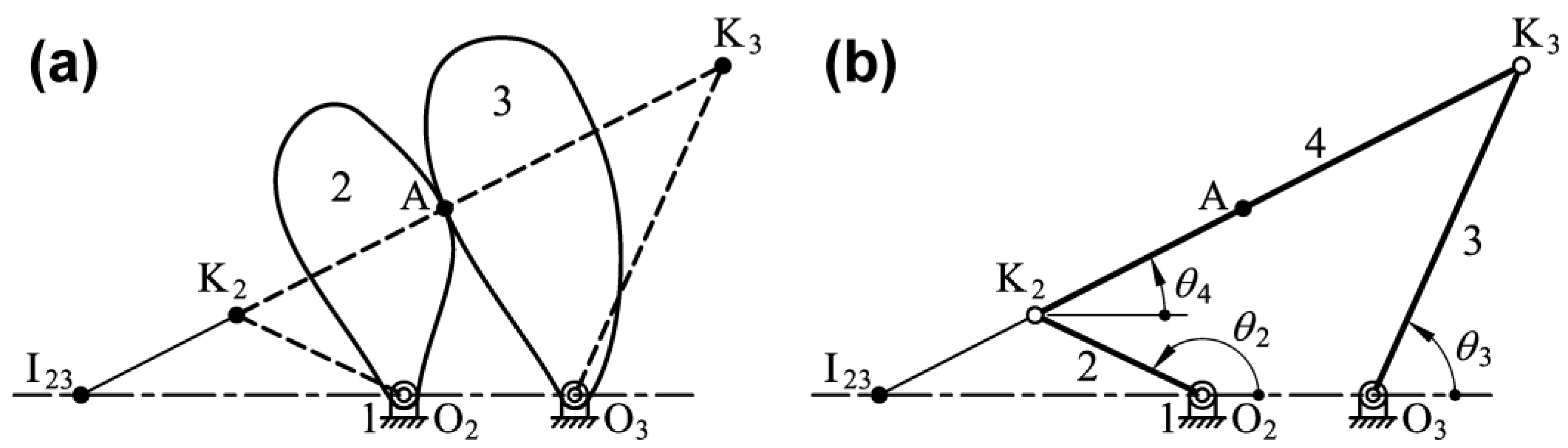
16] to present a more complete study on the inequivalence of the direct-contact mechanisms and their equivalent four-bar linkages in the aspect of jerk analysis. The direct-contact mechanisms consisting of higher pairs are classified into three classical types: (a) higher pairs with permanently invariant curvature centers, (b) higher pairs with suddenly changed curvature, and (c) higher pairs with continuously varying curvature; and their representative case studies are presented. Subsequently, the concept of “equivalent six-bar linkage” for direct-contact mechanisms is proposed in order to discuss the infeasibility of the equivalent four-bar linkage for jerk analysis in detail.
3. Kinematic Analysis for Direct-Contact Mechanisms Consisting of Higher Pairs with Permanently Invariant Curvature Centers: Planar Gear Mechanisms with Involute Spur Gears
For a direct-contact mechanism consisting of higher pairs with permanently invariant curvature centers, its equivalent four-bar linkage can also maintain a permanently invariant configuration at all instants. The planar gear mechanism with involute spur gears is a representative one of this type of direct-contact mechanisms. Thus, kinematic analysis for such a planar gear mechanism is presented in this Section.
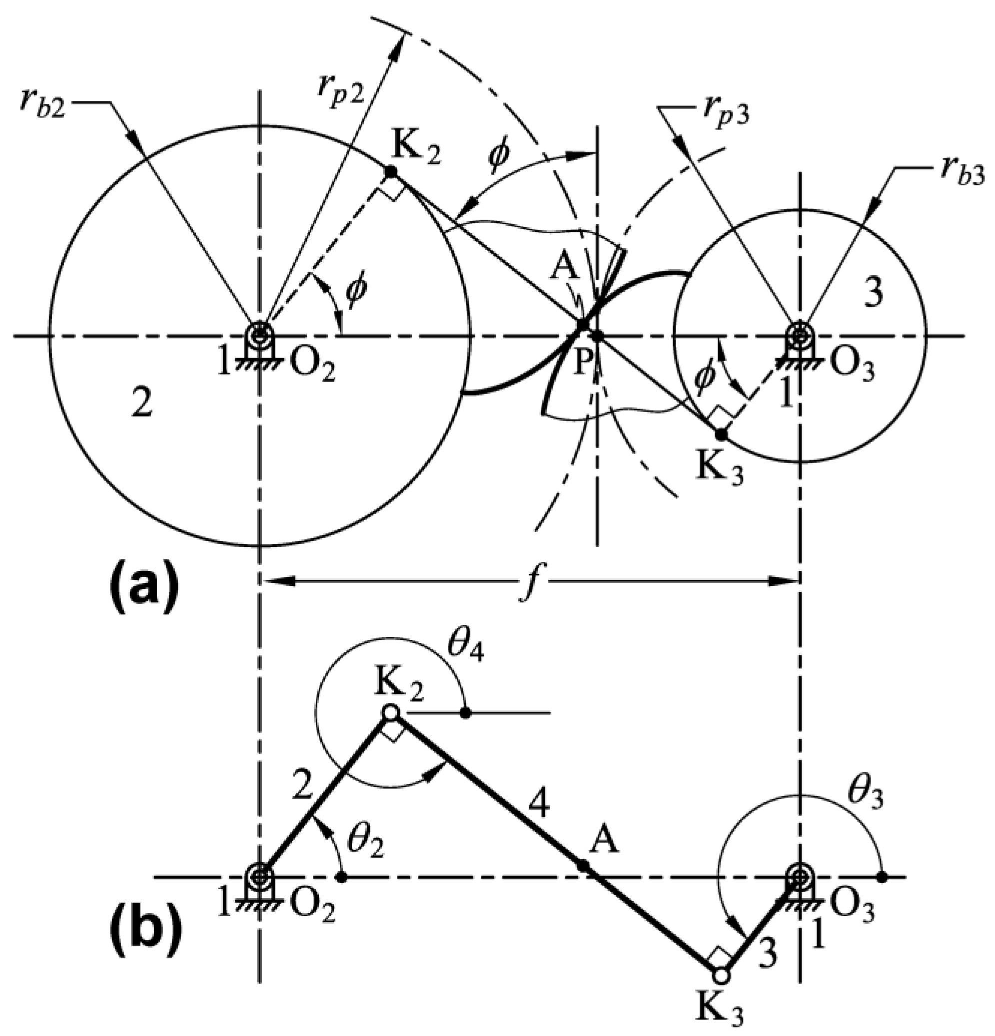
Figure 2a illustrates a planar gear mechanism, consisting of a frame (link 1), a driving gear (link 2), and a driven gear (link 3). The driving and driven gears are pivoted to the frame on points O
2 and O
3, respectively, while the center distance is
f. The driving and driven gears are both typically involute spur gears that have involute tooth profiles generated from their base circles with radii of
rb2 and
rb3, respectively. Thus, a constant angular velocity ratio between the two mating gears can be determined through the radii of their pitch circles
rp2 and
rp3. Points K
2 and K
3 are the centers of curvature of a pair of involute tooth profiles in contact at point A, respectively. The common normal at the contact point A (i.e. the line of action) must always pass through points K
2, K
3 and also the pitch point P. It is known that the line of action must always be the interior common tangent of the base circles of the two mating gears, while points K
2 and K
3 must always be coincident to the two points of tangency regardless of any positional change of the contact point A. Additionally, lines O
2K
2 and O
3K
3 are always parallel to each other, and the subtending acute angle between each of them and line O
2O
3 is always equal to the pressure angle
ϕ of the gear mechanism. As a result, the equivalent linkage of this planar gear mechanism is the four-bar linkage O
2K
2K
3O
3 shown in
Figure 2b, in which the coupler (link 4) of the linkage connects the centers of curvature of a pair of involute tooth profiles. The configuration of the equivalent four-bar linkage O
2K
2K
3O
3 shown in
Figure 2b is a permanently invariant crossed quadrilateral at all instants, according to the geometric characteristics of involute tooth profiles.
For the four-bar linkage that is shown in
Figure 2b, its link lengths are
r1 = O
2O
3 =
f,
r2 = O
2K
2 =
rb2 =
rp2cos
ϕ,
r3 = O
3K
3 =
rb3 =
rp3cos
ϕ, and
r4 = K
2K
3 =
f sin
ϕ, and the angular positions of links,
θ2,
θ3, and
θ4, are measured counterclockwise from line O
2O
3. Since the equivalent four-bar linkage is a permanently invariant crossed quadrilateral at all instants, thus the angular positions are invariantly
θ2 =
ϕ,
θ3 =
ϕ + 180°, and
θ4 =
ϕ + 270°. By substituting the values of
θ2,
θ3, and
θ4 into Equations (1) and (2), the angular velocities of links 3 and 4 of the equivalent linkage can be expressed as
Equation (8) shows that the angular velocity of the coupler (link 4) is zero, which agrees with the kinematic property of the stationary common normal. Afterwards, by substituting the values of
θ2,
θ3, and
θ4, and also
ω4 = 0 into Equations (3) and (4), the angular accelerations of links 3 and 4 of the equivalent linkage can be expressed as
Equation (10) shows that the angular acceleration of the coupler (link 4) is always greater than zero, which does not agree with the kinematic property of the stationary common normal. Furthermore, by substituting the values of
θ2,
θ3, and
θ4 and also
ω4 = 0 into Equations (5) and (6), the angular jerks of links 3 and 4 of the equivalent linkage can be expressed as
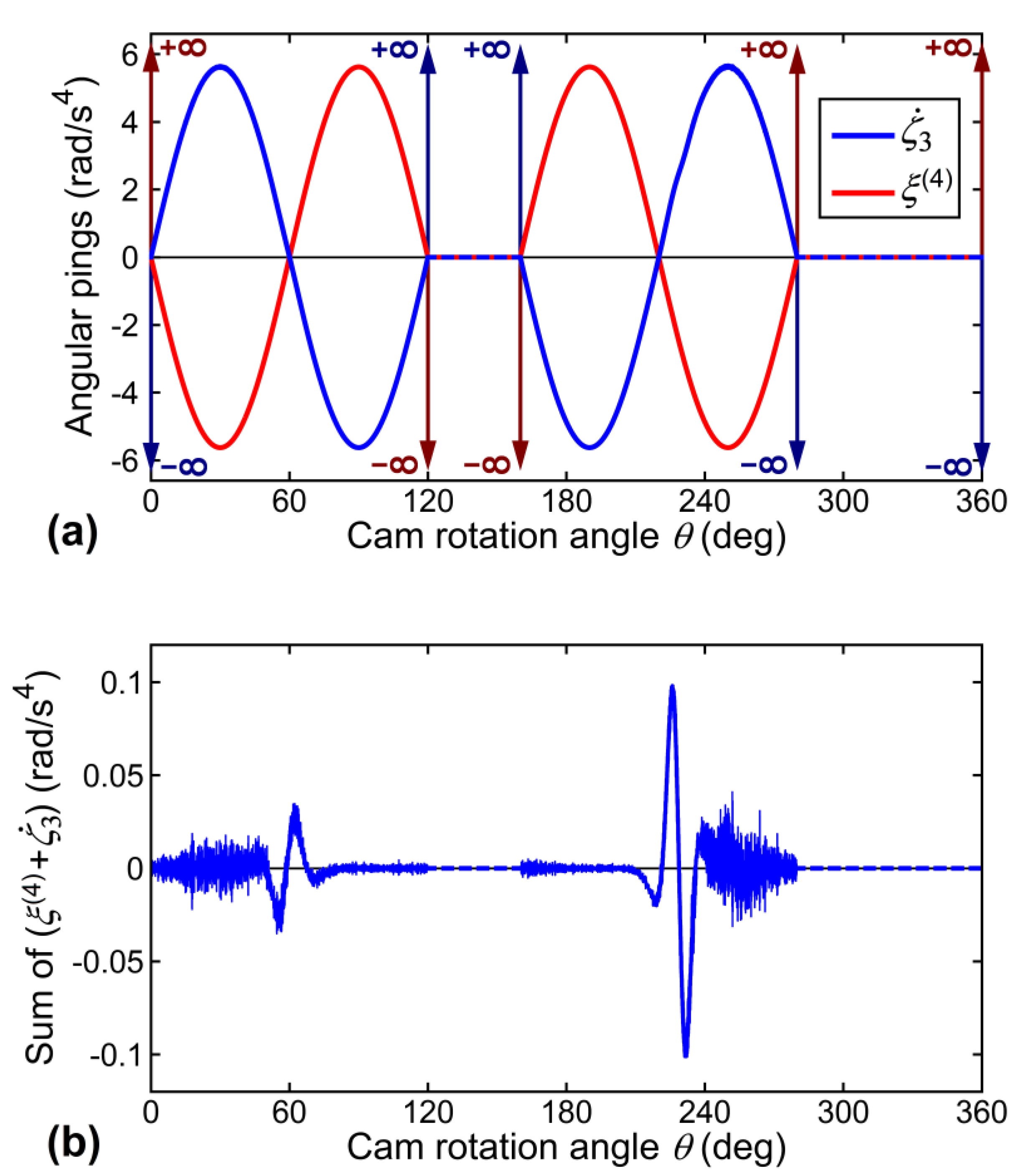
Equation (12) shows that the angular jerk of the coupler (link 4) is zero if and only if
α2 =
α3 = 0 when
ω2 ≠ 0 and
ω3 ≠ 0, otherwise it does not agree with the kinematic property of the stationary common normal.
When considering that the driving gear rotates at a constant angular velocity
ω2, its angular acceleration and jerk are
α2 = 0 and
ζ2 = 0, respectively. The driven gear will also rotate at a constant angular velocity
ω3, and its angular acceleration and jerk should be
α3 = 0 and
ζ3 = 0, respectively. From Equation (7), it is found that
Equation (13) undoubtedly agrees with the fundamental law of gearing [
17], which is, the angular velocity ratio between links 2 and 3 of the equivalent linkage is equal to that between the mating driving and driven gears. Hence, the equivalent four-bar linkage of the planar gear mechanism can give a correct value of angular velocity. Subsequently, by substituting
α2 = 0 into Equation (9), the angular acceleration of link 3 of the equivalent linkage is
It shows that the angular acceleration of link 3 of the equivalent linkage is zero, which is equal to that of the driven gear. Hence, the equivalent four-bar linkage of the planar gear mechanism can provide a correct value of angular acceleration. Furthermore, by substituting
α2 = 0,
α3 = 0, and
ζ2 = 0 into Equations (11) and (12), the angular jerks of links 3 and 4 of the equivalent linkage are
From Equations (7) and (15), the angular jerk of link 3 of the equivalent linkage can be further expressed as
From Equation (17), it can be found that
It shows that the angular jerk of link 3 of the equivalent linkage is zero if and only if
r2 =
r3. In other words, the angular jerk of link 3 of the equivalent linkage is equal to that of the driven gear if, and only if,
rp2 =
rp3. Hence, only when the angular velocity ratio between the two mating gears (
ω3/
ω2) is exactly negative one (−1), the equivalent four-bar linkage of the planar gear mechanism can give correct values of angular velocity, acceleration, and jerk. Otherwise, the equivalent four-bar linkage of the planar gear mechanism can only give correct values of angular velocity and acceleration.
In this case study, it is found that the equivalent four-bar linkage of a planar gear mechanism with a pair of involute spur gears is not able to give a correct value of jerk, unless the angular velocity ratio between the two mating gears is exactly negative one (−1).
4. Kinematic Analysis for Direct-Contact Mechanisms Consisting of Higher Pairs with Suddenly Changed Curvature: Disk Cam Mechanisms with a Circular-Arc Cam and an Oscillating Roller Follower
For a direct-contact mechanism consisting of higher pairs with suddenly changed curvature (i.e., discontinuous curvature), two equivalent four-bar linkages may simultaneously exist at a certain instant. The disk cam mechanism with a circular-arc cam and an oscillating roller follower is a representative one of this type of direct-contact mechanisms. Thus, kinematic analysis for such a disk cam mechanism is presented in this Section.
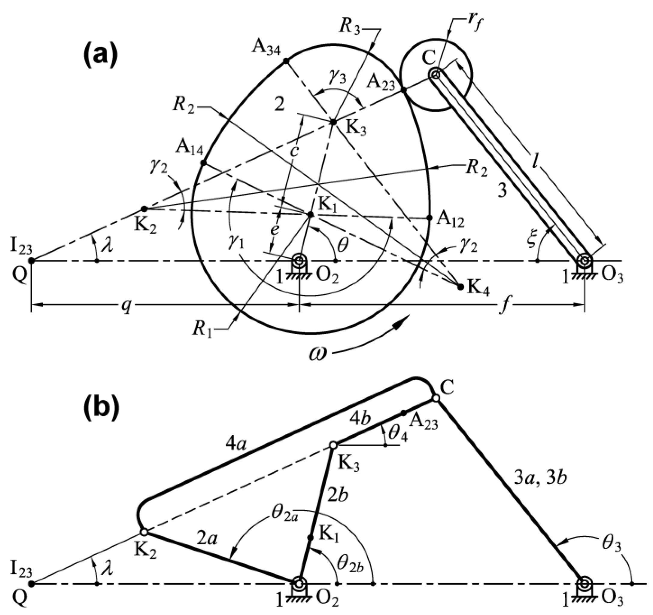
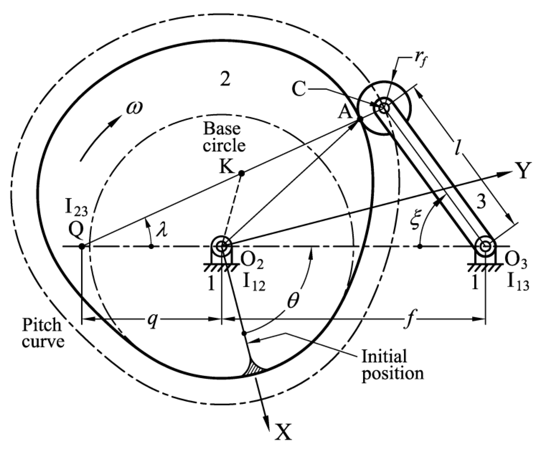
Figure 3a illustrates a disk cam mechanism, consisting of a frame (link 1), a circular-arc cam (link 2), and an oscillating roller follower (link 3). The cam and the follower are pivoted to the frame on points O
2 and O
3, respectively, while the center distance is
f. The profile of the circular-arc cam is essentially composed of four circular arcs with three radii
R1,
R2, and
R3, respectively. Points K
1, K
2, K
3, and K
4 are the circular centers (also the centers of curvature) of the four circular arcs, respectively. Points A
12, A
23, A
34, and A
14 on the cam profile are the points of tangency of each two adjacent circular arcs, respectively. The circular arc between points A
12 and A
14 has a radius of
R1 and a circular-arc angle of
γ1, the circular arc between points A
12 and A
23 or between points A
14 and A
34 has a radius of
R2 and a circular-arc angle of
γ2, and the circular arc between points A
23 and A
34 has a radius of
R3 and a circular-arc angle of
γ3. In this case, points O
2, K
1, and K
3 are collinear, while the distance between points O
2 and K
1 is
e, and that between points K
1 and K
3 is
c. The follower has an arm length of
l and a roller radius of
rf. The cam rotation angle
θ is measured counterclockwise from line O
2O
3 to line O
2K
1, while the angular position of the follower
ξ is measured clockwise from line O
2O
3 to line O
3C for point C being the roller center. When the values of
R1,
R2,
R3, and
c are given, then from ΔK
1K
2K
3 (or ΔK
1K
3K
4) and the cosine law, the circular-arc angles
γ1,
γ2, and
γ3 can be determined by
It should be noted that the geometric relation of
γ1 + 2
γ2 +
γ3 = 360° must be satisfied. Once the cam profile has been designed, the angular position of the follower
ξ =
ξ(
θ) can be accordingly determined. The contact normal can also be determined by locating instant center I
23. By labeling instant center I
23 as Q and O
2Q =
q, as shown in
Figure 3a, point Q can be located by [
11,
12,
17]
From ΔO
3QC and the cosine law, line QC, which is collinear with the contact normal, can then be determined by
Thus, from ΔO
3QC and the sine law, the angular position of the contact normal
λ, measured counterclockwise from line O
2O
3 to line QC, can be expressed as
The equivalent linkage of this disk cam mechanism is a four-bar linkage whose coupler connects the circular center of one of the four circular-arc profiles and the roller center. The equivalent linkage corresponding to each circular-arc profile is an invariant one (i.e., its link lengths are invariant). Thus, the disk cam mechanism can be successively replaced by four invariant equivalent linkages (with different constant link lengths), as the circular-arc cam rotates a complete cycle. However, when considering a special situation that the contact point between the cam and the follower is point A
23 (or one of the remaining three points of tangency), the equivalent four-bar linkages at that instant are shown in
Figure 3b. It can be observed that two equivalent four-bar linkages O
2K
2CO
3 and O
2K
3CO
3 simultaneously exist at that instant. For clarity of illustration, the four-bar linkage O
2K
2CO
3 consists of links 1, 2
a, 3
a, and 4
a, and the four-bar linkage O
2K
3CO
3 consists of links 1, 2
b, 3
b, and 4
b. The links 3
a and 3
b overlap with each other. The couplers 4
a and 4
b, also overlapping with each other, are collinear with the common normal at the contact point A
23 that passes through points Q, K
2, K
3, and C at that instant.
For the four-bar linkages that are shown in
Figure 3b, their link lengths are
r1 = O
2O
3 =
f,
r2a = O
2K
2,
r2b = O
2K
3 =
e +
c,
r3a =
r3b = O
3C =
l,
r4a = K
2C =
R2 +
rf and
r4b = K
3C =
R3 +
rf. The angular positions of links,
θ2a,
θ2b,
θ3, and
θ4, are measured counterclockwise from line O
2O
3. From ΔO
2K
2K
3 and the cosine law, the link length of
r2a can be further determined by
From ΔO
2K
3C and the cosine law, the distance O
2C at that instant can be determined by
Hence, from ΔO
2K
3C, ΔO
2O
3C, and the cosine law, the values of the cam rotation angle
θ and the angular position of the follower
ξ at that instant can be determined by
Subsequently, the values of
θ2a and
θ2b at that instant can be determined by
Additionally, the values of
θ3 and
θ4 at that instant can be determined by
It is known that when the circular-arc cam rotates a complete cycle, the follower will instantaneously undergo non-continuous accelerations and infinite jerks as the circular-arc cam is in contact with the follower at one of the four points of tangency (i.e., points A
12, A
14, A
34, and A
23) successively, although the velocity of the follower can be continuous at those instants. A practical example is given in order to evaluate such phenomena. A circular-arc cam with
R1 = 50 mm,
R2 = 120 mm,
R3 = 32.5 mm,
c = 40 mm, and
e = 20 mm is designed to drive an oscillating roller follower with
l = 100 mm and
rf = 15 mm, while the center distance is
f = 120 mm. From Equations (19) to (21), the circular-arc angles are
γ1 = 203.832°,
γ2 = 26.570°, and
γ3 = 103.028°. Such a disk cam mechanism is proportionally shown in
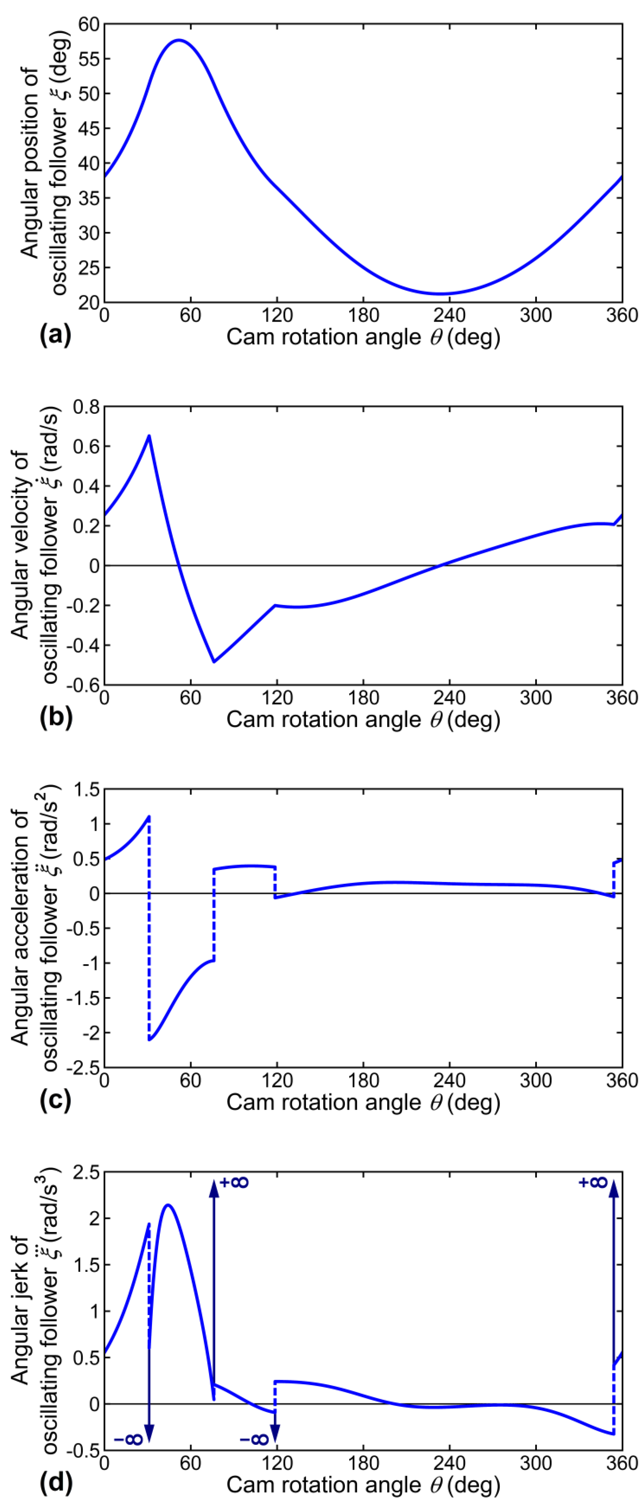
Figure 3a. The circular-arc cam is specified to rotate counterclockwise with a constant angular velocity of
ω = 1 rad/s. The angular position of the follower,
ξ, in a complete cam rotation cycle is shown in
Figure 4a, while its corresponding time derivatives (i.e., the angular velocity
acceleration
and jerk
obtained through the use of numerical differentiation, are shown in
Figure 4b–d. The follower obviously undergoes non-continuous accelerations and infinite jerks when
θ = 31.076°, 76.168°, 118.6°, and 354.043°. Additionally,
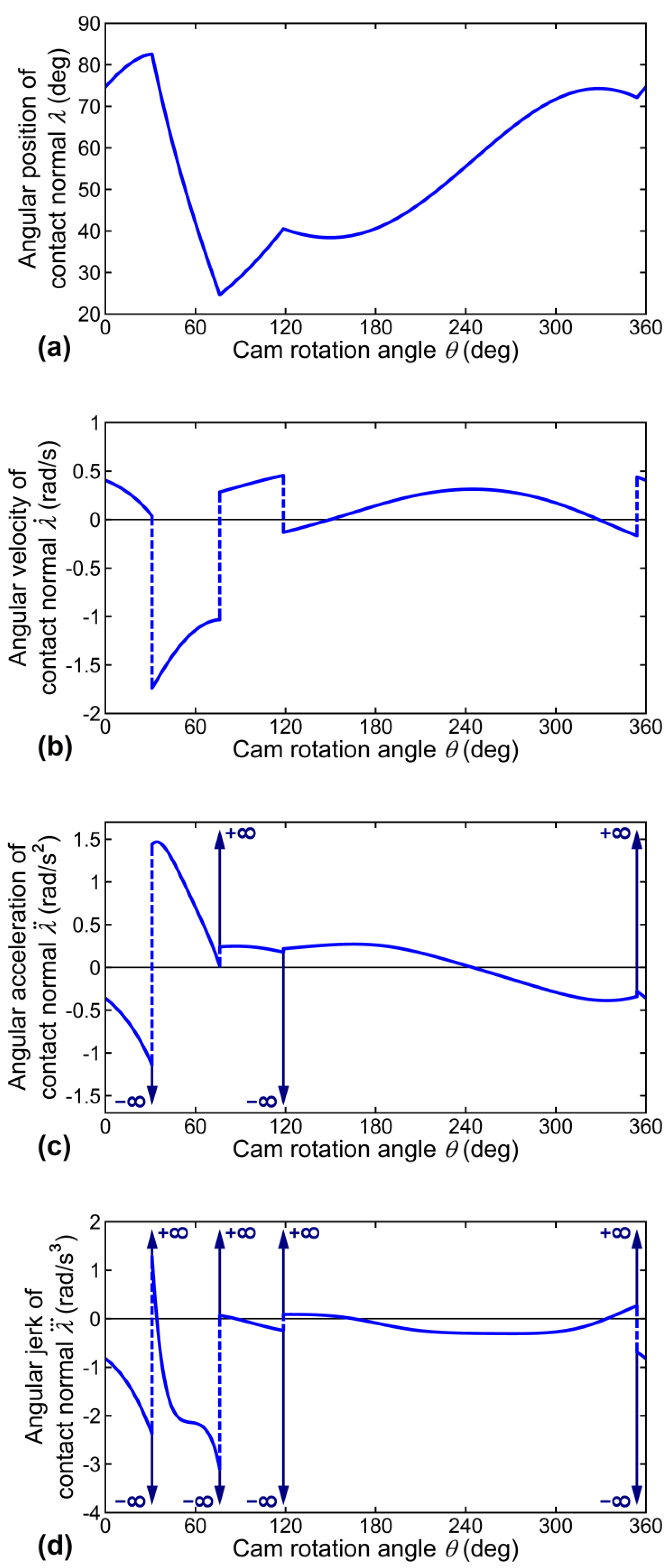
Figure 5a shows the angular position of the contact normal,
λ, in a complete cam rotation cycle, while its corresponding time derivatives (i.e., the angular velocity
acceleration
and jerk
obtained through the use of numerical differentiation, are shown in
Figure 5b–d. Although the contact normal can have continuously varying angular positions, it obviously undergoes non-continuous velocities and infinite accelerations and jerks when
θ = 31.076°, 76.168°, 118.6°, and 354.043°. When the contact point between the cam and the follower is point A
23 as shown in
Figure 3a, link lengths of the equivalent four-bar linkages shown in
Figure 3b are
r1 =
f = 120 mm,
r2a = O
2K
2 = 68.716 mm [from Equation (25)],
r2b = O
2K
3 =
e +
c = 60 mm,
r3a =
r3b = O
3C =
l = 100 mm,
r4a = K
2C =
R2 +
rf = 135 mm, and
r4b = K
3C =
R3 +
rf = 47.5 mm. At that instant, from Equations (27) to (31),
θ = 76.168°,
ξ = 51.328°,
θ2a = 161.538°,
θ2b = 71.168°,
θ3 = 128.672°, and
θ4 = 24.654° can be obtained. For the equivalent four-bar linkage O
2K
2CO
3 (consisting of links 1, 2
a, 3
a, and 4
a), its angular velocities, accelerations, and jerks at that instant, calculated by using Equations (1) to (6) with
ω2 = 1 rad/s,
α2 = 0 rad/s
2, and
ζ2 = 0 rad/s
3, are
For the equivalent four-bar linkage O
2K
3CO
3 (consisting of links 1, 2
b, 3
b, and 4
b), its angular velocities, accelerations, and jerks at that instant, calculated by using Equaions (1) to (6), are
It is found that
ω3a =
ω3b = 0.484 rad/s and
α3a ≠
α3b, which agree with the situations that are shown in
Figure 4b,c that the follower undergoes a non-continuous angular acceleration, although its angular velocity can be continuous at that instant. However, it is also found that
ζ3a = −0.209 rad/s
3 and
ζ3b = −0.047 rad/s
3 are finite values, which cannot correctly reflect an instantaneously infinite follower jerk as that shown in
Figure 4d. As to the results of the coupler, it can be found that
ω4a ≠
ω4b, which agrees with the situation shown in
Figure 5b that the contact normal undergoes a non-continuous angular velocity, although its angular position can be continuous at that instant. However, the remaining results of
α4a = 0.242 rad/s
2,
α4b = 0.018 rad/s
2,
ζ3a = −0.209 rad/s
3, and
ζ3b = −0.047 rad/s
3 are all finite values, which cannot correctly reflect the instantaneously infinite acceleration and jerk as those shown in
Figure 5c,d.
In this case study, when the circular-arc cam is in contact with its follower at a point of tangency of two adjacent circular arcs, the coupler acceleration of the equivalent linkage, α4, does not agree with the angular acceleration of the contact normal, at that instant. Unreasonable values of α4 obtained in acceleration analysis [with the use of Equation (4)] unavoidably lead to incorrect values of ζ3 and ζ4 when performing jerk analysis because α4 is involved in both Equations (5) and (6).
In addition, if a special case of
R1 =
R2 =
R3 and
c = 0 is given, the circular-arc cam will degenerate to an eccentric circular cam, while points K
1, K
2, K
3, and K
4 will coincide with the circular center of the eccentric circular cam. It is known that an eccentric circular cam mechanism has an invariant equivalent four-bar linkage (without link-length variations) that can completely duplicate the motion transmission between the cam and the follower [
3]. Such an invariant equivalent four-bar linkage can give correct values of angular velocity, acceleration, and jerk for all instants. As compared with the eccentric circular cam profile having constant curvature, the curvature of the circular-arc cam is suddenly changed at the points of tangency of each two adjacent circular arcs. As the circular-arc cam and its follower are in contact at such a point of tangency, the suddenly changed curvature of the cam profile is not considered in sudden link-length variations of the equivalent four-bar linkages. Thus, the two equivalent four-bar linkages simultaneously existing at that instant are both not able to correctly reflect an infinite jerk of the follower.
5. Kinematic Analysis for Direct-Contact Mechanisms Consisting of Higher Pairs with Continuously Varying Curvature: Disk Cam Mechanisms with a Double-Dwell Cam and an Oscillating Roller Follower
For a direct-contact mechanism consisting of higher pairs with continuously varying curvature, some link lengths of its equivalent four-bar linkage may continuously vary during the whole motion cycle. The disk cam mechanism with a double-dwell cam and an oscillating roller follower is a representative one of this type of direct-contact mechanisms. Thus, kinematic analysis for such a disk cam mechanism is presented in this Section.
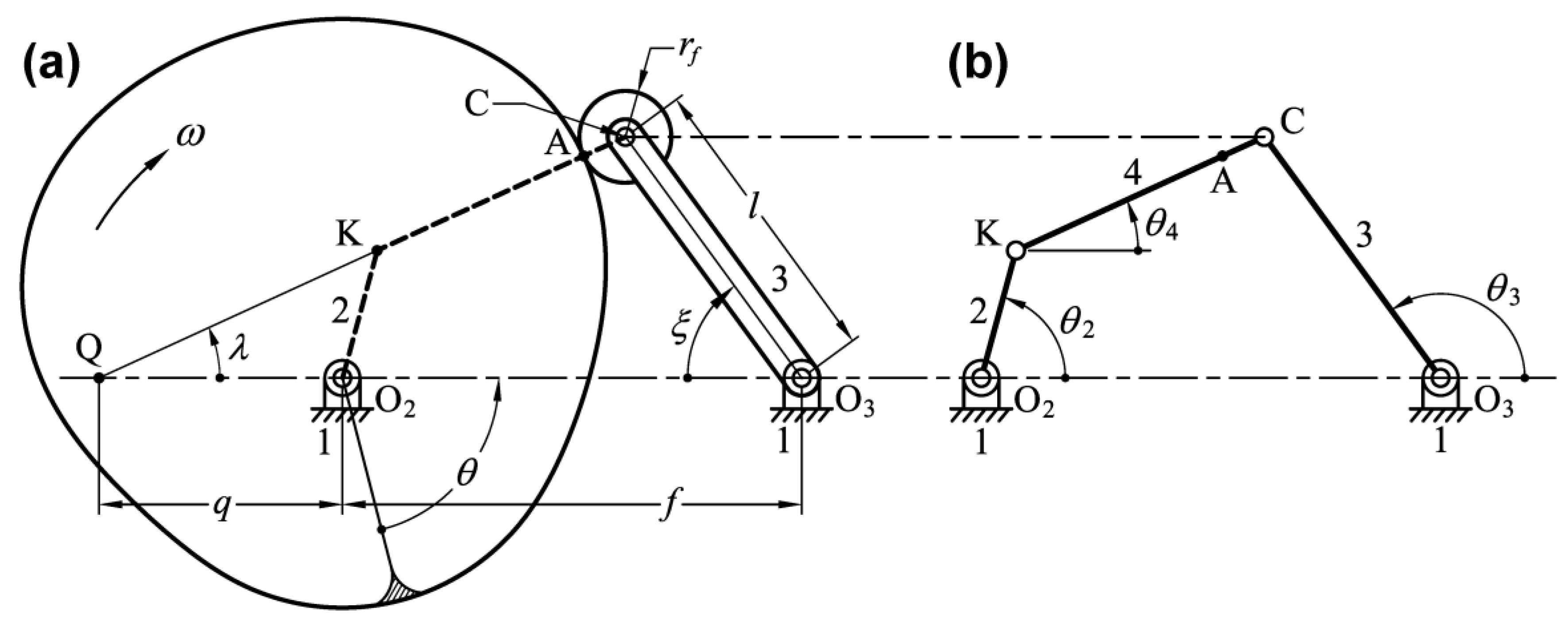
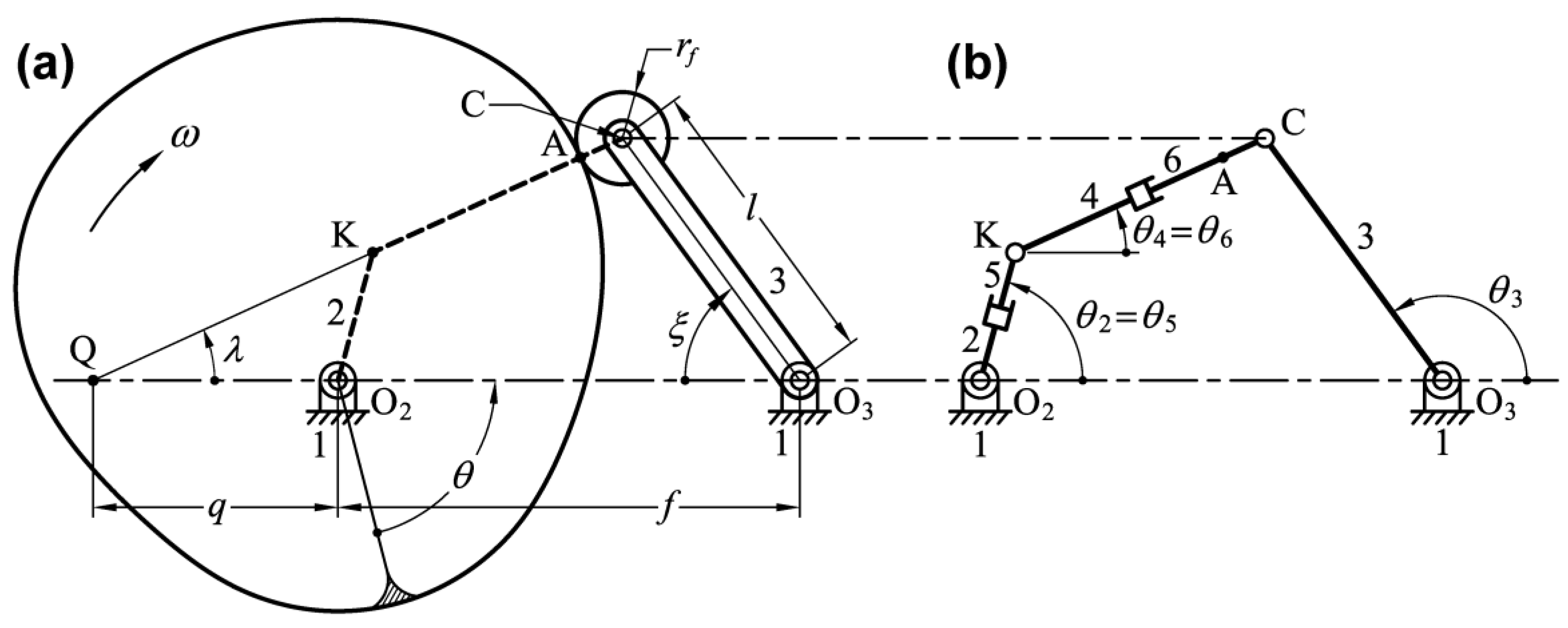
Figure 6 illustrates a disk cam mechanism, consisting of a frame (link 1), a double-dwell cam (link 2), and an oscillating roller follower (link 3). The cam and the follower are pivoted to the frame on points O
2 and O
3, respectively, while the center distance is
f. The follower has an arm length of
l and a roller radius of
rf. The contact normal always passes through the roller center C, the contact point A, the center of curvature of the cam profile K, and also the instant velocity center I
23. By setting up a Cartesian coordinate system X-Y fixed on the cam and with its origin at the fixed pivot O
2, the cam profile coordinates may be expressed in terms of the cam rotation angle
θ, which is measured against the direction of cam rotation from the reference radial on cam to line O
2O
3. The cam is to rotate clockwise with a constant angular velocity of
ω rad/s. By labeling instant center I
23 as Q and O
2Q =
q, the parametric vector equations of the theoretical cam profile coordinates can be expressed as [
12,
17,
18]
where
in which,
ξ(
θ) is the angular displacement function of the oscillating follower [
12,
17,
18]:
where,
rb is the radius of the base circle and
s(
θ) is the prescribed angular displacement program (or called displacement curve [
17]) of the follower. Thus,
v(
θ) [=
ds(
θ)/
dθ] in Equation (35) is the angular velocity curve of the follower (in unit of rad/rad or dimensionless). It can be seen that line QC is the contact normal between the cam and the roller follower. Additionally, the parametric vector equations of the pitch curve coordinates can be expressed as [
18]
The radius of curvature of the pitch curve,
ρC, can then be determined by [
18]
where,
a =
a(
θ) [=
dv(
θ)/
dθ] is the angular acceleration curve of the follower (in unit of rad/rad
2 or 1/rad). Therefore, the radius of curvature of the cam profile,
ρ, can be obtained by [
18]
The equivalent linkage of this disk cam mechanism is a four-bar linkage whose coupler connects the center of curvature of the cam profile, K, and the roller center, C, as shown in
Figure 7. For the four-bar linkage O
2KCO
3 shown in
Figure 7b, its link lengths are
r1 = O
2O
3 =
f,
r2 = O
2K,
r3 = O
3C =
l, and
r4 = KC =
ρC =
ρ +
rf, and the angular positions of links,
θ2,
θ3, and
θ4, are measured counterclockwise from line O
2O
3. It must be noted that the values of
ρC and
ρ are positive when the corresponding cam profile is convex, as the figure shows. When part of the cam profile is concave, the corresponding values of
ρC and
ρ are negative, and the corresponding coupler length will be
r4 = KC = −
ρC = −(
ρ +
rf). From ΔO
2QK and the cosine law, the link length of
r2 can be further determined by
in which, the length QK corresponding to a convex cam profile, as shown in
Figure 7a, is
Subsequently, the values of
θ2,
θ3, and
θ4 can be determined by
Because the double-dwell cam profile is with continuously varying curvature, the link lengths
r2 and
r4 of its equivalent linkage therefore continuously vary with respect to the cam rotation angle
θ.
A practical example is given in order to evaluate the kinematic characteristics of the equivalent four-bar linkage. A cam system requires the oscillating roller follower to oscillate 25° clockwise with cycloidal motion [
17,
19] while the cam rotates clockwise from 0° to 120°, dwell for the next 40°, return with cycloidal motion [
17,
19] for 120° cam rotation, and dwell for the remaining 80°. The design parameters for the cam mechanism are:
f = 80 mm,
l = 52 mm,
rb = 40 mm, and
rf = 8 mm. Such a disk cam mechanism is proportionally shown in
Figure 6 and
Figure 7a. The double-dwell cam is specified to rotate clockwise with a constant angular velocity of
ω = 1 rad/s.
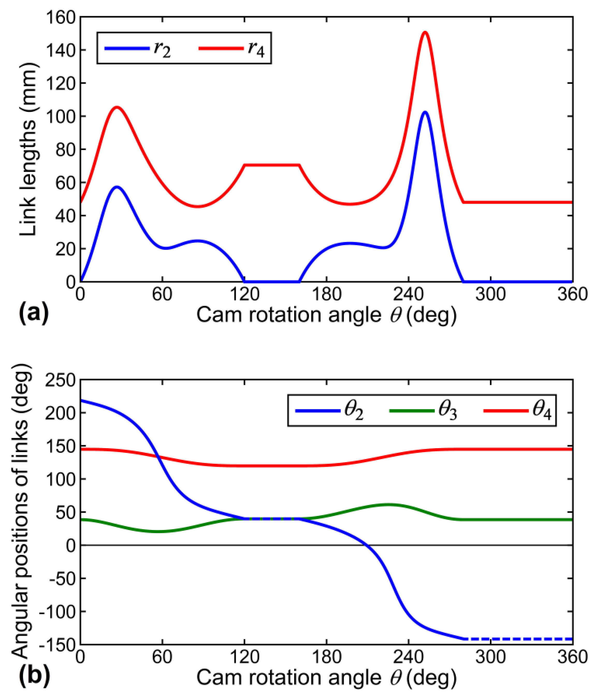
Figure 8 shows the variations of link lengths and angular positions for the equivalent linkage of the disk cam mechanism. As seen, the link lengths of
r2 and
r4 are continuously variable. The link length of
r2 is zero when
θ = 120°~160° and
θ = 280°~360°, for which the follower dwells. The link length of
r4 essentially agrees with the radius of curvature of the pitch curve,
ρC. The variational curve of
θ2 is specially drawn by dashed lines when
θ = 120°~160° and
θ = 280°~360°, since the situations of
r2 = 0 and QK = 0 simultaneously occur to yield an undefined result of tan
−1(0/0) in Equation (44). Additionally, the variational curves of
θ3 and
θ4 essentially agree with the variational trends of (180° −
ξ) and
λ, respectively.
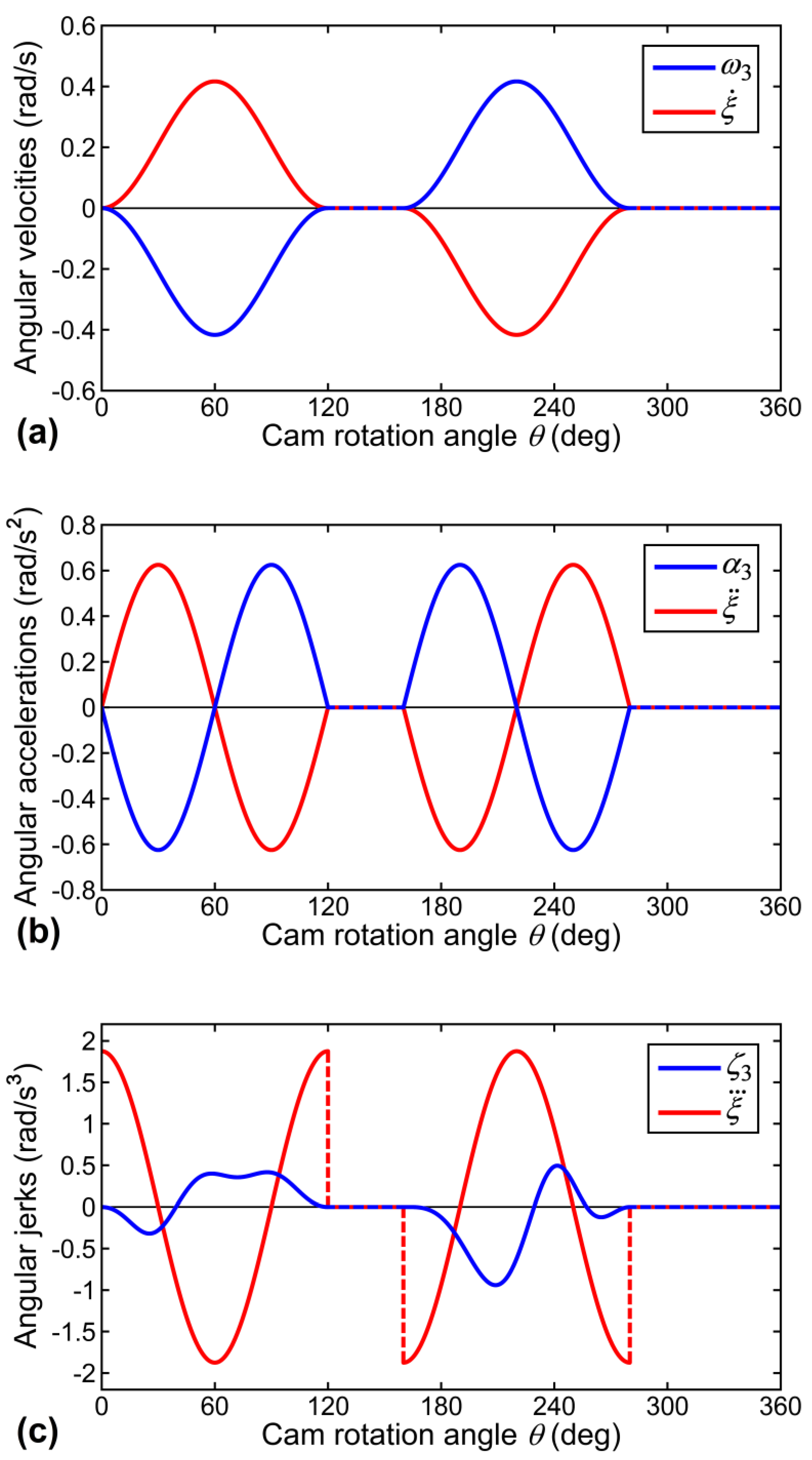
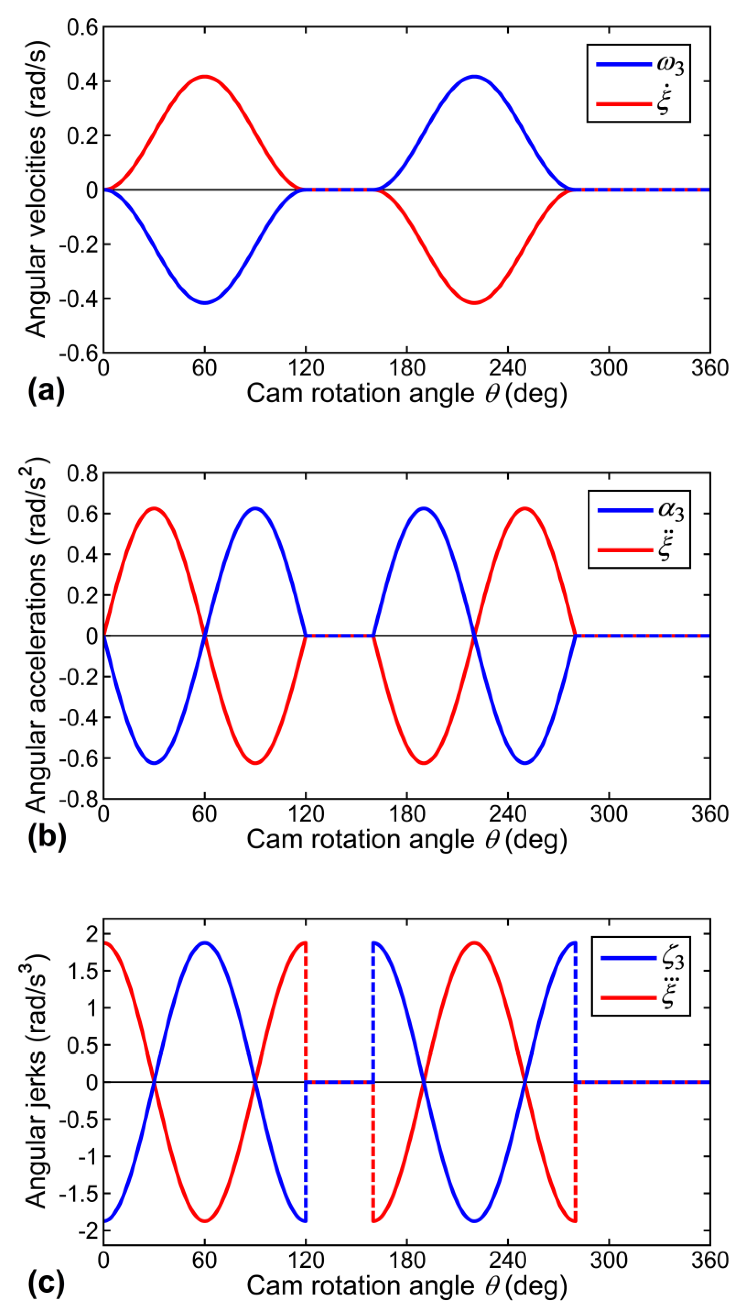
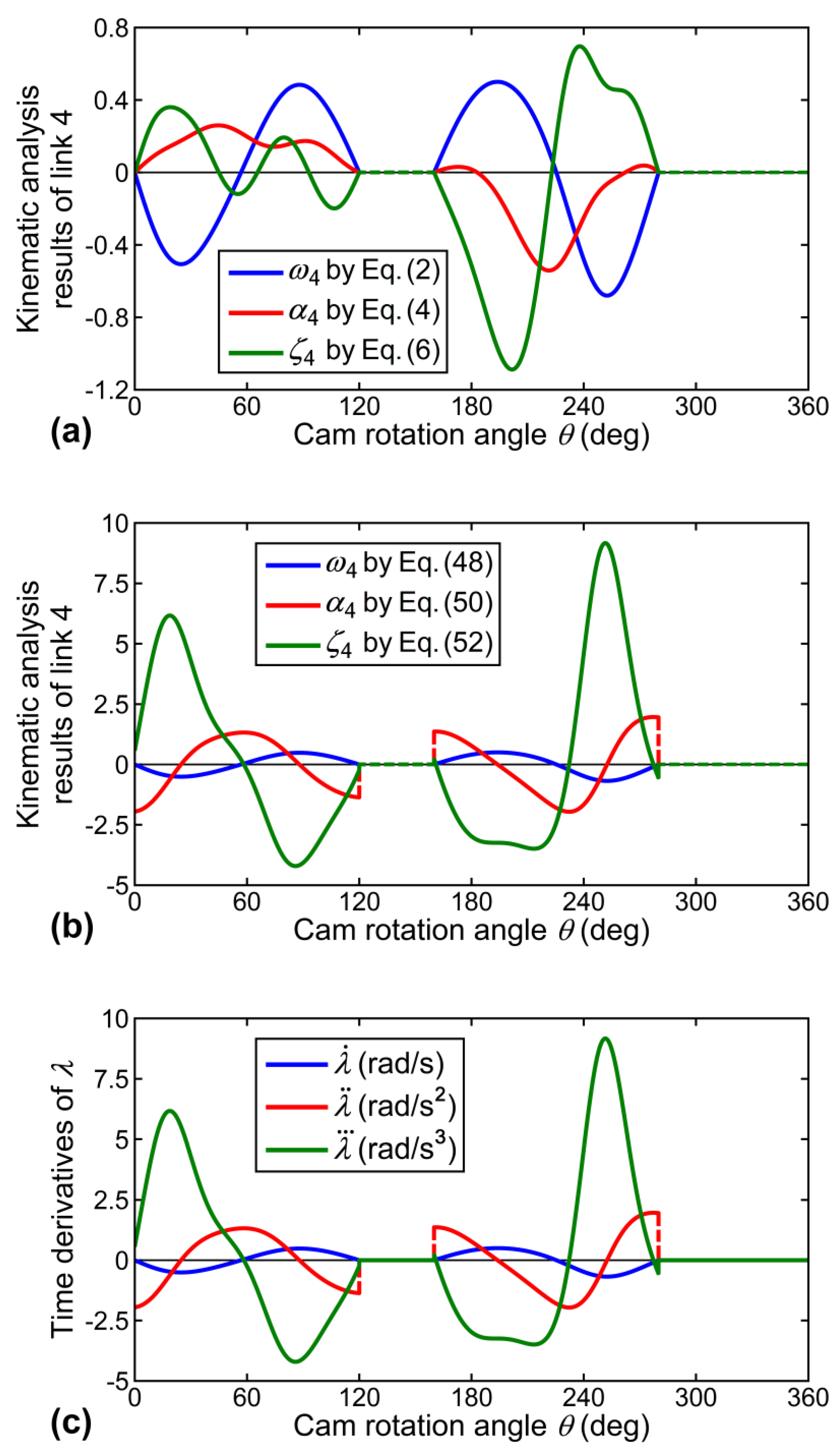
The kinematic analysis results for the equivalent four-bar linkage [calculated by using Equations (1), (3), and (5) with
ω2 = 1 rad/s,
α2 = 0 rad/s
2 and
ζ2 = 0 rad/s
3], as well as the angular velocity
acceleration
and jerk
of the follower, are all shown in
Figure 9. The situations of
and
can be intuitively observed in the figure. Comparison results between the obtained motion curves are presented in
Figure 10 in order to justify the situations. The numerical result for sum of
merely ranges between ±1 × 10
−15 rad/s, and that for sum of
also merely ranges between ±8 × 10
−15 rad/s
2. The negligible numerical errors can justify the correctness of
and
However, the numerical result for sum of
considerably ranges between ±1.88 rad/s
3. As a result, the equivalent four-bar linkage of the presented disk cam mechanism with a double-dwell cam and an oscillating roller follower is not able to give a correct value of jerk.
The double-dwell cam that is presented in this case study is an ordinary disk cam profile with continuously varying curvature. Thus, its equivalent four-bar linkage corresponding to two infinitesimally closed profile points in contact with the follower cannot exactly have identical link lengths. For most disk cam mechanisms, it can be deduced that their equivalent four-bar linkages should not be able to give a correct value of jerk, because the continuously varying curvature of the cam profiles is not considered in continuous link-length variations of their equivalent four-bar linkages.
6. Kinematic Analysis for Direct-Contact Mechanisms Consisting of Higher Pairs with Continuously Varying Curvature via the Concept of Equivalent Six-Bar Linkage
In the above three case studies, almost all of the results indicate that the equivalent four-bar linkage for a direct contact mechanism cannot give a correct value of jerk. Especially the two case studies for disk cam mechanisms both indicate that the influence of suddenly changed or continuously varying curvature of the cam profile on sudden or continuous link-length variations of the equivalent four-bar linkage is not considered, which could be a major cause of incorrectness in jerk analysis. In order to justify this deduction, the concept of “equivalent six-bar linkage” for disk cam mechanisms considering the time rate of change of the cam profile curvature is presented in this Section. Kinematic analysis of the equivalent six-bar linkage for the disk cam mechanism that is presented in
Section 5 is performed in order to evaluate whether the equivalence of a disk cam mechanism and its equivalent six-bar linkage in jerk analysis can exist.
For the disk cam mechanism that is shown in
Figure 11a (the same as those shown in
Figure 6 and
Figure 7a), its equivalent six-bar linkage shown in
Figure 11b consists of a frame (link 1), a frame-pivoted linear actuator (links 2 and 5), a floating linear actuator (links 4 and 6), and a frame-pivoted arm (link 3). Each linear actuator essentially consists of two links that are connected by a prismatic joint, such as a slider in its guide, so that the two links can have a relative translation in one direction. Links 4 and 5 in the linear actuators are pinned on the center of curvature of the cam profile, K, while links 2 and 6 in the linear actuators are pinned on the fixed pivot O
2 and on the roller center C, respectively. The link lengths of the six-bar linkage are defined as
r1 = O
2O
3 =
f,
r2 = O
2K,
r3 = O
3C =
l, and
r4 = KC =
ρC =
ρ +
rf, and the angular positions of links,
θ2,
θ3,
θ4,
θ5, and
θ6, are measured counterclockwise from line O
2O
3. Although the configuration of the six-bar linkage is identical to that of the four-bar linkage shown in
Figure 7b, its link lengths of
r2 and
r4 are both variables that can exactly reflect the time rate of change of the cam profile curvature. That is, at any instant,
r2 is a variable that describes the relative displacement in the frame-pivoted linear actuator (links 2 and 5) between points O
2 and K, and
r4 is a variable that describes the relative displacement in the floating linear actuator (links 4 and 6) between points K and C. For such a single-loop six-bar linkage with three degree-of-freedom, by specifying
θ2,
r2, and
r4 as the three input parameters, a constrained motion can be achieved. Since
θ2 =
θ5 and
θ4 =
θ6, by using the vector loop method, the two unknowns
θ3 and
θ4 in displacement equations can be solved simultaneously. Alternatively, Equations (40) to (46) can also be used to determine the values of
r2,
r4,
θ2,
θ3, and
θ4.
By using the vector loop method to solve the velocity equations simultaneously, the analytical expressions of the angular velocities of link 3 (
ω3) and links 4 and 6 (
ω4) can be derived as
in which,
ω2 and
are the known input velocities, which can be determined through the first time derivatives of
θ2,
r2, and
r4 shown in Equations (40) to (44). Subsequently, by using the vector loop method to solve the acceleration equations simultaneously, the analytical expressions of the angular accelerations of link 3 (
α3) and links 4 and 6 (
α4) can be derived as
in which,
α2 and
are the known input accelerations, which can be determined through the second time derivatives of
θ2,
r2, and
r4 shown in Equations (40) to (44). Furthermore, by using the vector loop method to solve the jerk equations simultaneously, the analytical expressions of the angular jerks of link 3 (
ζ3) and links 4 and 6 (
ζ4) can be derived as
in which,
ζ2 and
are the known input jerks, which can be determined through the third time derivatives of
θ2,
r2, and
r4 shown in Equations (40) to (44). The derived analytical expressions can be used to evaluate the kinematic characteristics of the equivalent six-bar linkage obtained from a direct-contact mechanism.
The practical example that is given in
Section 5 is adopted again in order to evaluate the kinematic characteristics of the equivalent six-bar linkage. The variations of link lengths and angular positions for the equivalent six-bar linkage are the same as those shown in
Figure 8. It must be noted that, according to the influence of the time rate of change of the cam profile curvature on the link-length variations, the angular velocity of the frame-pivoted linear actuator (
ω2) and the linear velocities of both linear actuators
and
should not be constants while the cam rotates clockwise with a constant angular velocity of
ω = 1 rad/s (this situation can also be directly observed in
Figure 8 that the variation curves of
θ2,
r2, and
r4 are not horizontals). Thus, the variations of
ω2,
and
with respect to the cam rotation angle
θ (that is proportional to time), as well as those for
α2,
ζ2,
and
are all estimated through numerical differentiation in this case study, since cumbersome equations must be dealt with for deriving their analytical expressions.
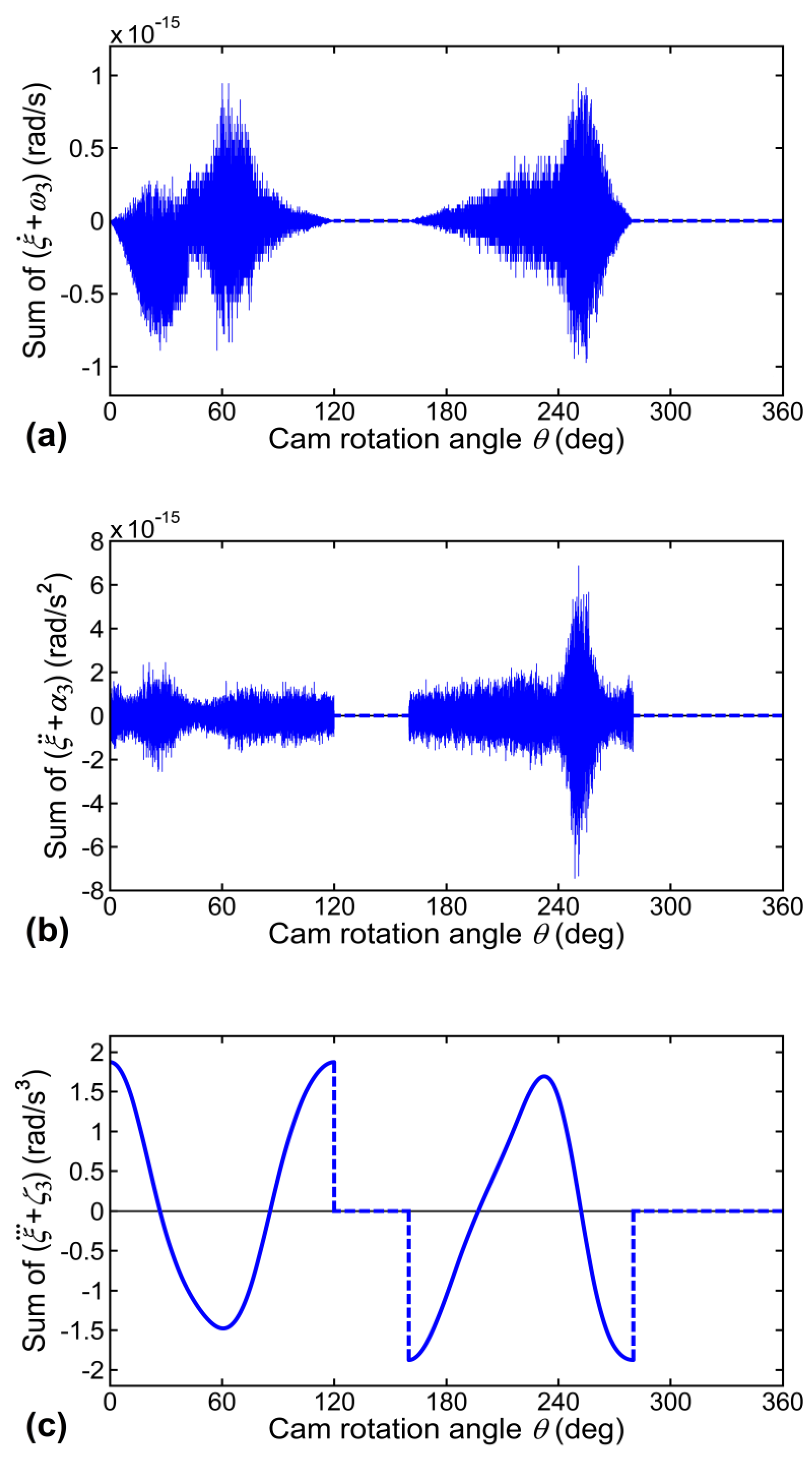
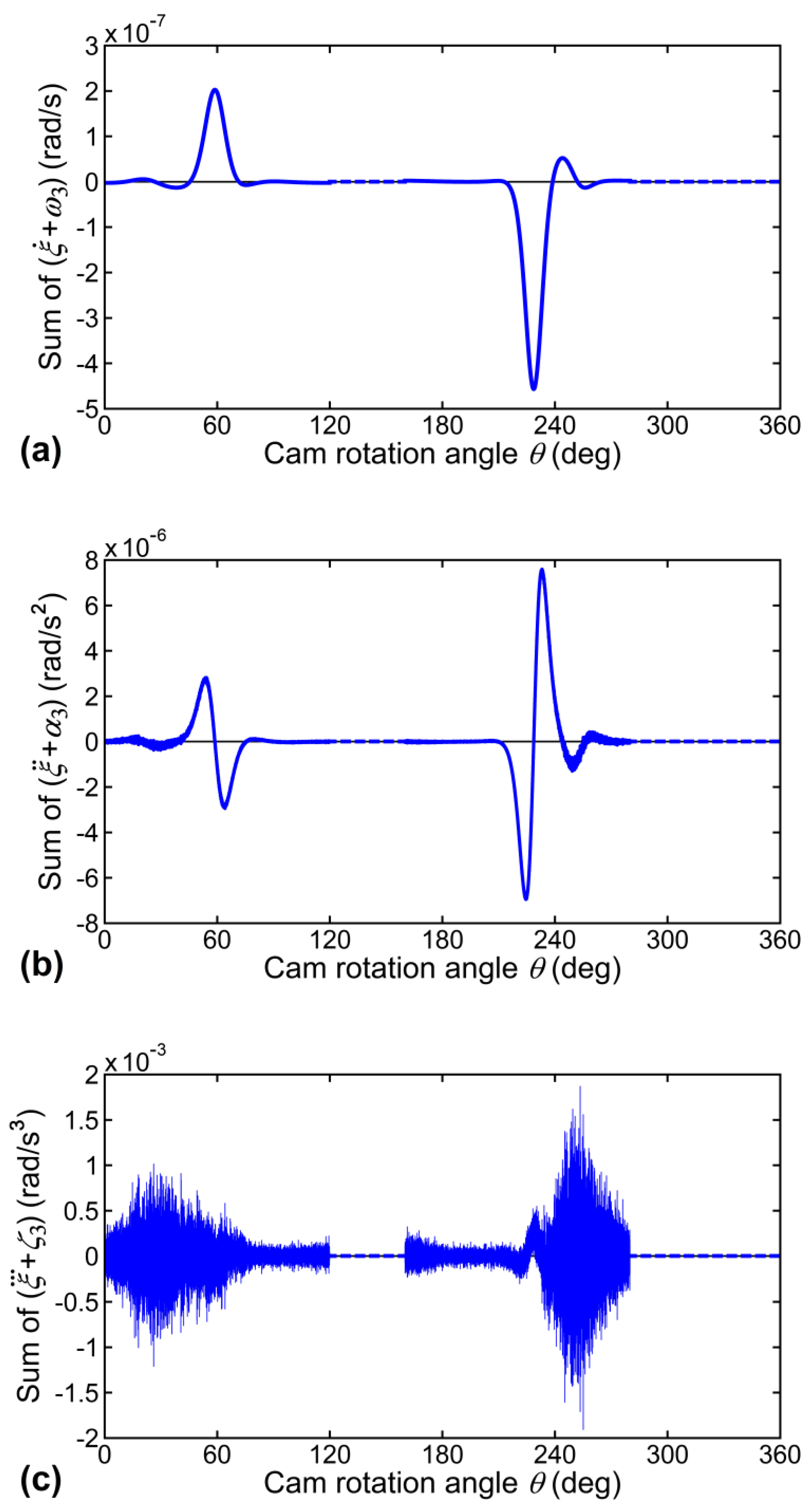
The kinematic analysis results for the equivalent six-bar linkage [calculated by using Equations (47), (49), and (51)], as well as the angular velocity
acceleration
and jerk
of the follower, are all shown in
Figure 12. The situations of
and
can be intuitively observed in the figure. Comparison results between the obtained motion curves are presented in
Figure 13 in order to justify the situations. The numerical result for sum of
merely ranges between −4.57 × 10
−7 and 2.03 × 10
−7 rad/s, and that for sum of
also merely ranges between −7 × 10
−6 and 7.6 × 10
−6 rad/s
2. As to the numerical result for sum of
it meaningfully ranges between −1.91 × 10
−3 and 1.87 × 10
−3 rad/s
3, although the accuracy of
ζ3 [calculated by using Equation (51)] is unavoidably influenced by the cumulative errors of
ζ2,
and
(estimated through numerical differentiation). The quite slight numerical errors can justify the correctness of
and
In this case study, it is found that the equivalent six-bar linkage of a disk cam mechanism with a double-dwell cam and an oscillating roller follower is able to give a correct value of jerk. Likewise, the equivalence of most disk cam mechanisms and their equivalent six-bar linkages in jerk analysis can exist.
According to the presented case study, the reasonability of the deduction mentioned above can therefore be justified because the link-length variations of the equivalent six-bar linkage can exactly reflect the time rate of change of the cam profile curvature and result in the correctness in jerk analysis.

