Static Balancing of Wheeled-legged Hexapod Robots

 , and
, and 
Abstract
1. Introduction
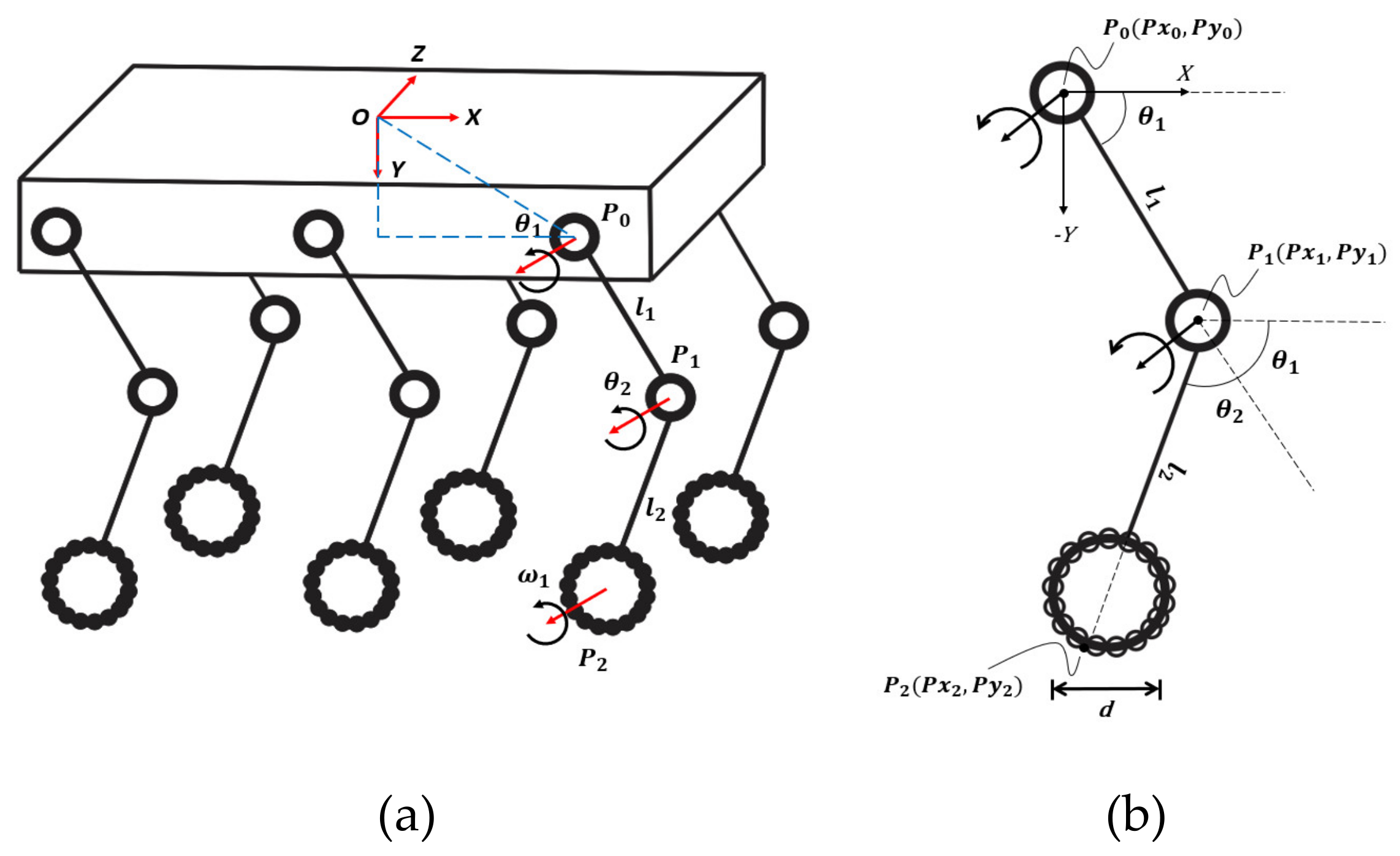
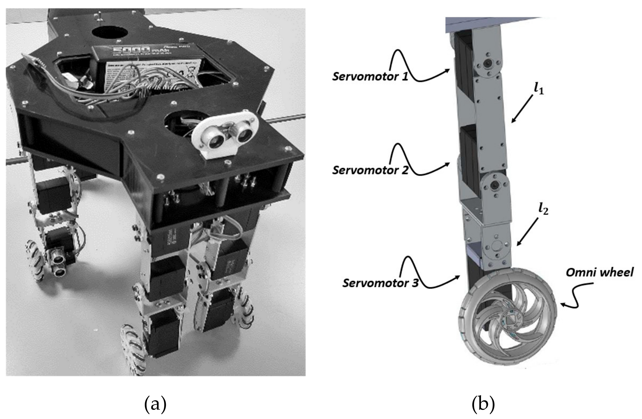
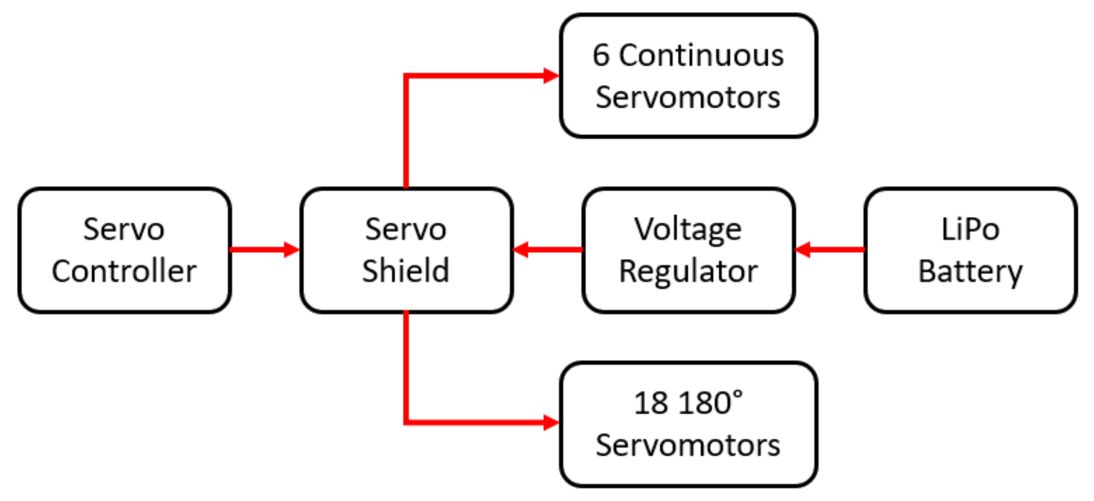
2. A Wheeled-Legged Hexapod Robot
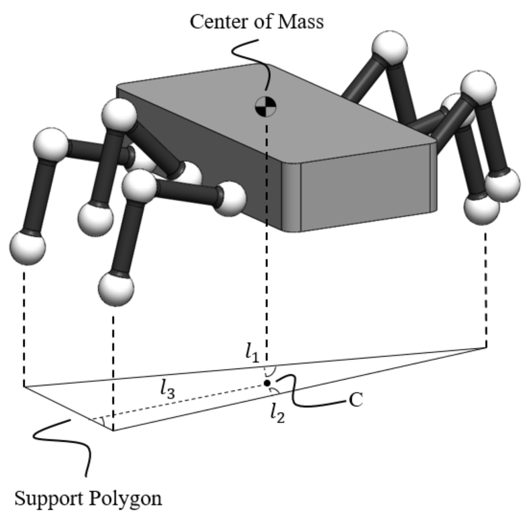
3. Static Balancing
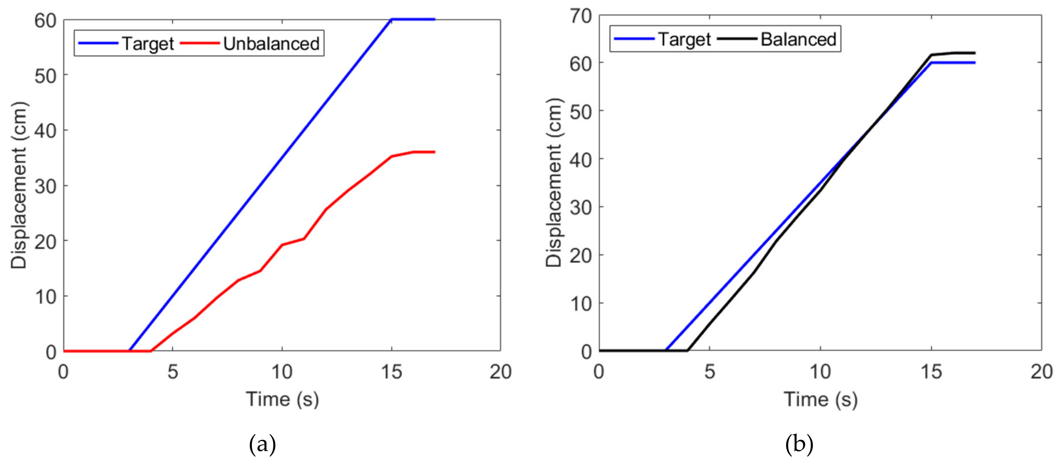
3.1. Balancing Issues in Motion Operation
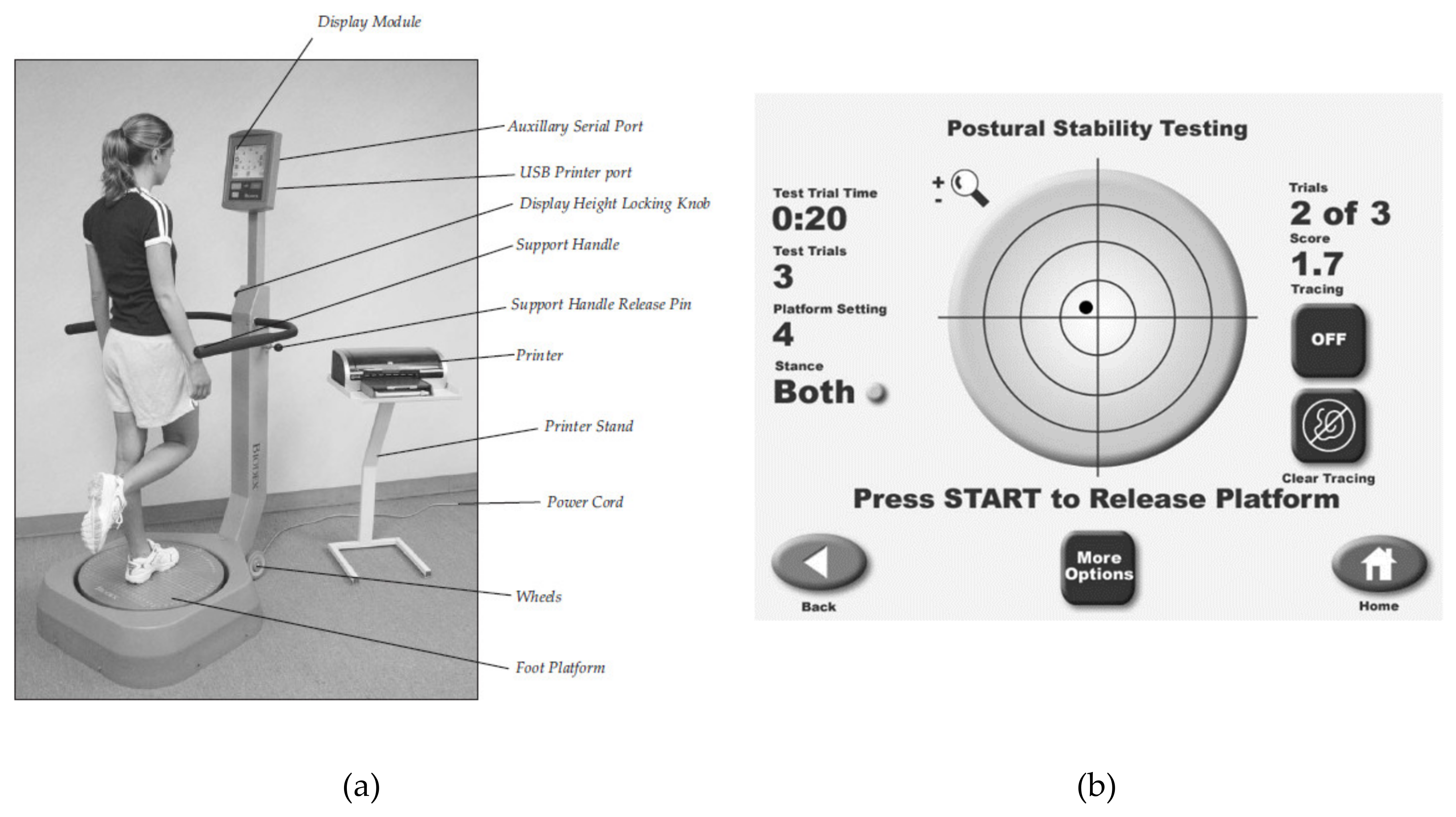
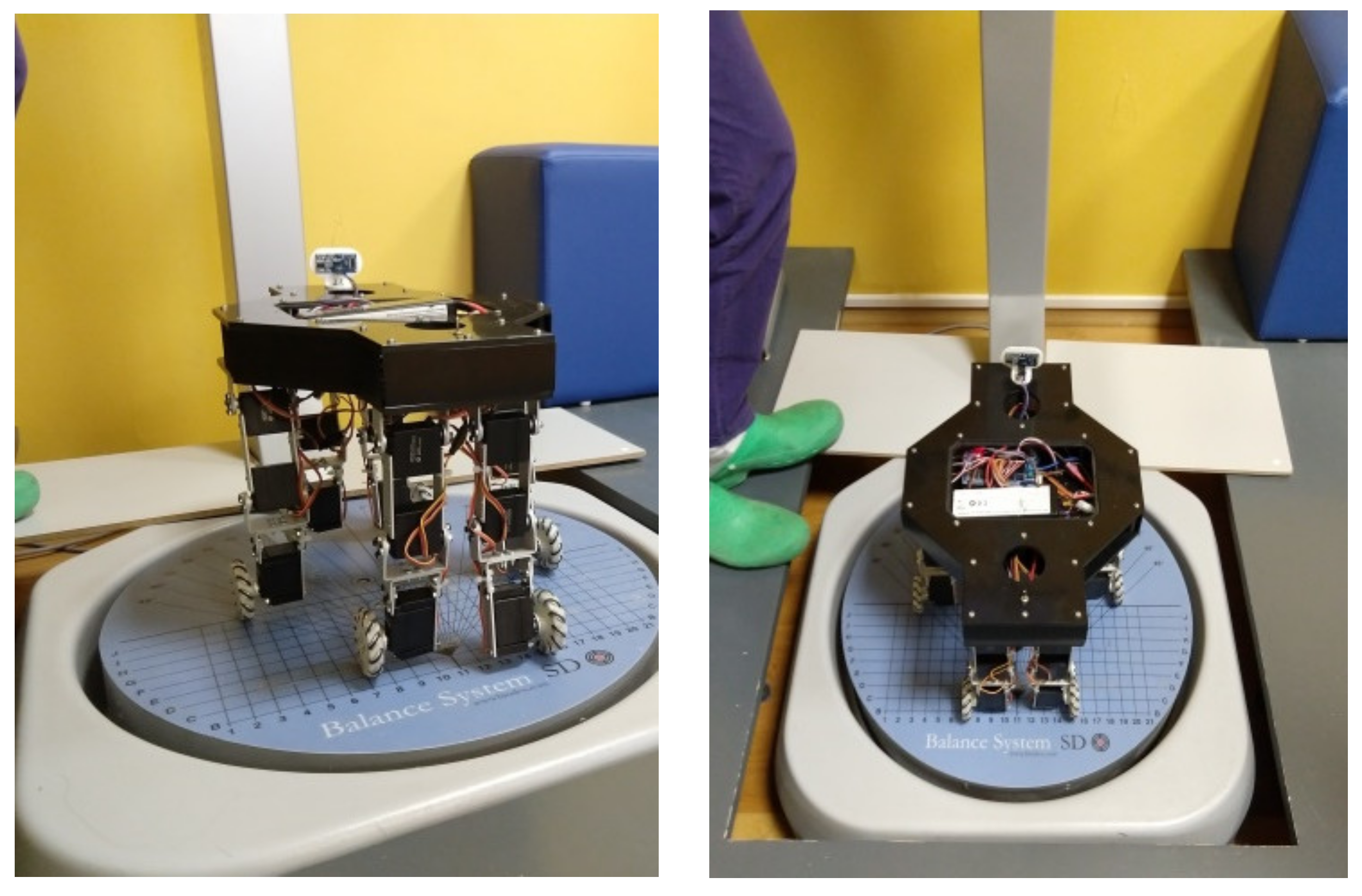
3.2. Biodex Balance System SD
Tests
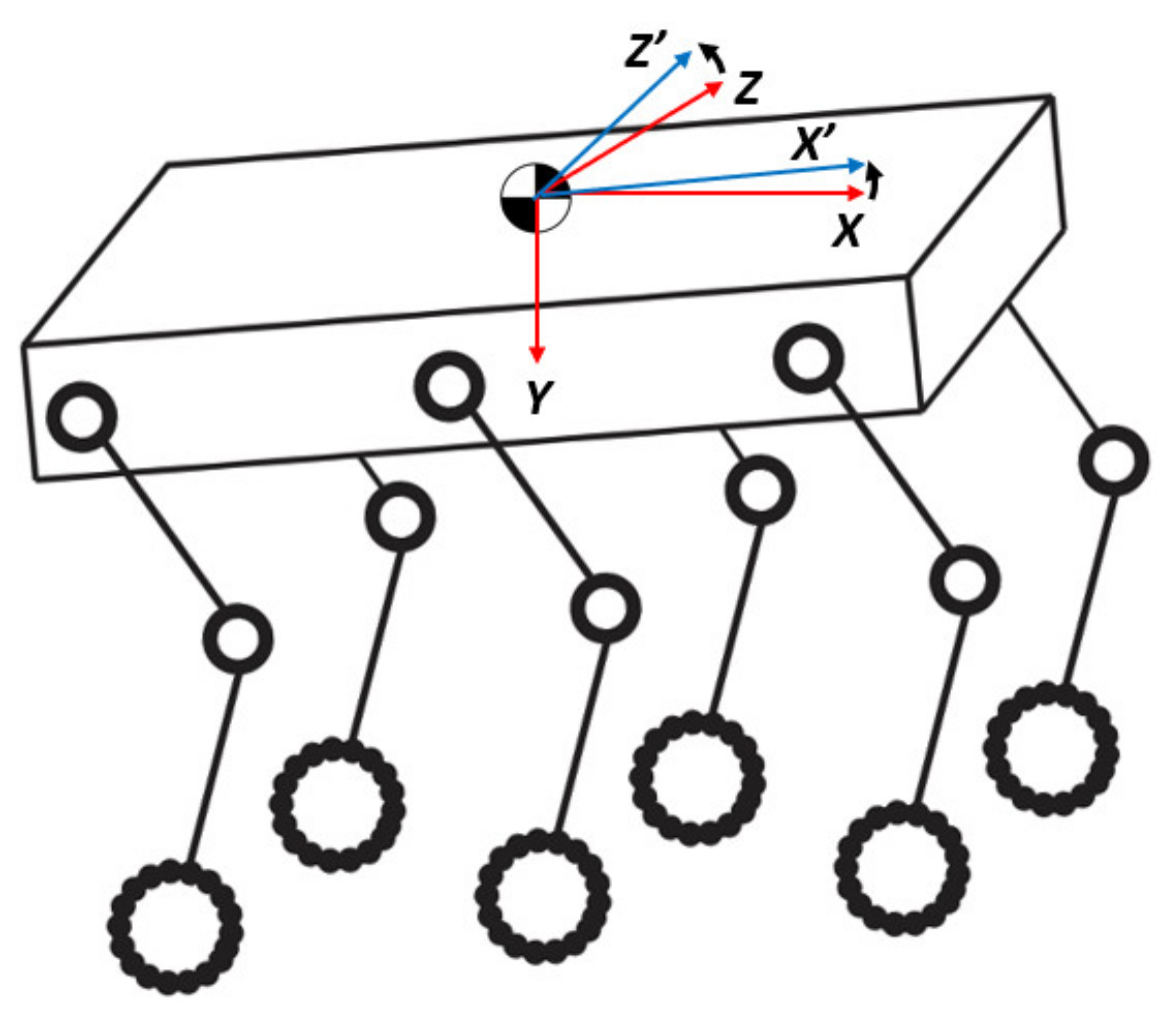
3.3. Zero Moment Point Criterion
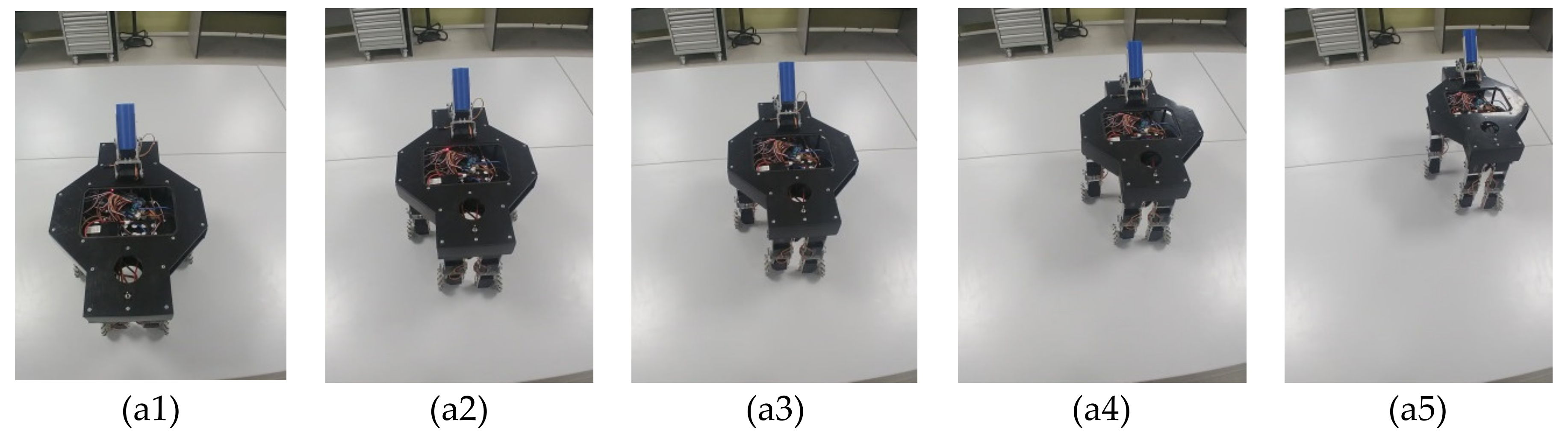
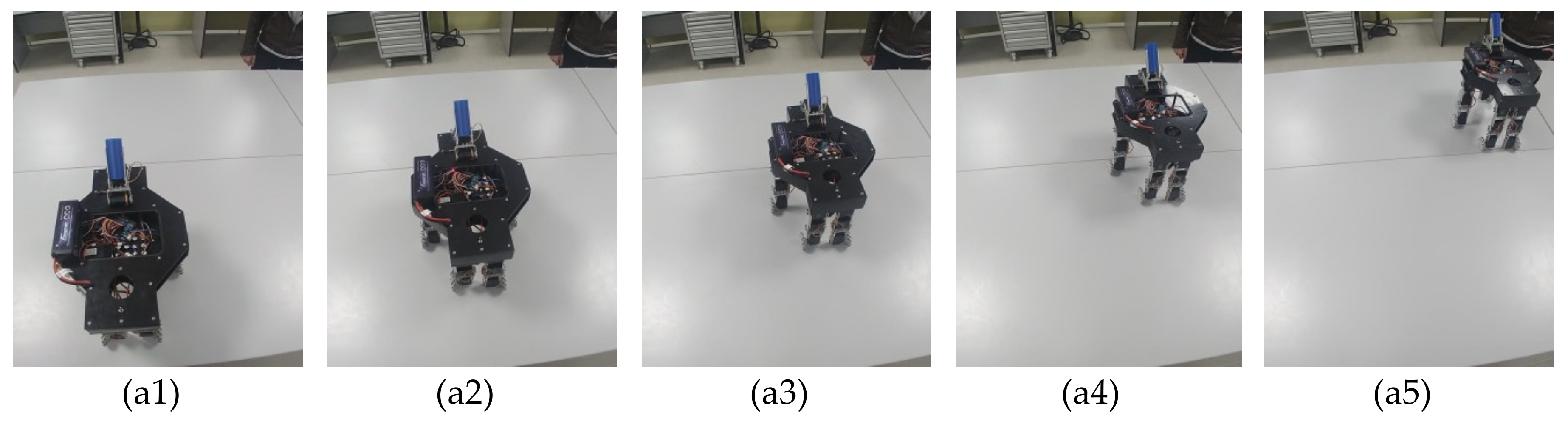
4. Experimental Tests
5. Conclusions
Author Contributions
Funding
Acknowledgments
Conflicts of Interest
References
- Orozco-Magdaleno, E.C.; Cafolla, D.; Castillo-Castañeda, E.; Carbone, G. A Service Hexapod Robot as Hospital Guide. Int. J. Mech. Control. 2019, 20, 121–126. [Google Scholar]
- Schwarz, M.; Rodehutskors, T.; Schreiber, M.; Behnke, S. Hybrid driving-stepping locomotion with the wheeled-legged robot Momaro. In Proceedings of the 2016 IEEE International Conference on Robotics and Automation (ICRA); 2016; pp. 5589–5595. [Google Scholar]
- Carbone, G.; Gomez-Bravo, F. Motion and Operation Planning of Robotic Systems: Background and Practical Approaches; Springer: Dordrecht, The Netherlands, 2015. [Google Scholar]
- De Viragh, Y.; Bjelonic, M.; Bellicoso, D.; Jenelten, F.; Hutter, M. Trajectory Optimization for Wheeled-Legged Quadrupedal Robots Using Linearized ZMP Constraints. IEEE Robot. Autom. Lett. 2019, 4, 1633–1640. [Google Scholar] [CrossRef]
- Carbone, G.; Shrot, A.; Ceccarelli, M. Operation Strategy for a Low-Cost Easy-Operation Cassino Hexapod. Appl. Bionics Biomech. 2007, 4, 149–156. [Google Scholar] [CrossRef]
- Copilusi, C.; Ceccarelli, M.; Carbone, G. Design and numerical characterization of a new leg exoskeleton for motion assistance. Robotica 2014, 33, 1147–1162. [Google Scholar] [CrossRef]
- Copilusi, C.; Ceccarelli, M.; Dumitru, N.; Carbone, G. Design and Simulation of a Leg Exoskeleton Linkage for a Human Rehabilitation System. In The 11th IFToMM International Symposium on Science of Mechanisms and Machines. Mechanisms and Machine Science; Visa, I., Ed.; Springer: Cham, Germany, 2014; Volume 18, pp. 117–125. [Google Scholar]
- Chen, W.-H.; Lin, H.-S.; Lin, Y.-M.; Lin, P.-C. TurboQuad: A Novel Leg–Wheel Transformable Robot With Smooth and Fast Behavioral Transitions. IEEE Trans. Robot. 2017, 33, 1025–1040. [Google Scholar] [CrossRef]
- Bai, L.; Hu, H.; Chen, X.; Sun, Y.; Ma, C.; Zhong, Y. CPG-Based Gait Generation of the Curved-Leg Hexpod Robot with Smooth Gait Transition. Sensors 2019, 19, 3705. [Google Scholar] [CrossRef]
- Bjelonic, M.; Bellicoso, D.; De Viragh, Y.; Sako, D.; Tresoldi, F.D.; Jenelten, F.; Hutter, M. Keep Rollin’—Whole-Body Motion Control and Planning for Wheeled Quadrupedal Robots. IEEE Robot. Autom. Lett. 2019, 4, 2116–2123. [Google Scholar] [CrossRef]
- Carbone, G.; Ceccarelli, M. A Low-Cost Easy-Operation Hexapod Walking Machine. Int. J. Adv. Robot. Syst. 2008, 5, 21. [Google Scholar] [CrossRef]
- Giordano, P.R.; Fuchs, M.; Albu-Schaffer, A.; Hirzinger, G. On the kinematic modeling and control of a mobile platform equipped with steering wheels and movable legs. In Proceedings of the 2009 IEEE International Conference on Robotics and Automation, Kobe, Japan, 12–17 May 2009; Institute of Electrical and Electronics Engineers (IEEE): Piscataway, NJ, USA; pp. 4080–4087. [Google Scholar]
- Tedeschi, F.; Carbone, G. Design of a Novel Leg-Wheel Hexapod Walking Robot. Robotics 2017, 6, 40. [Google Scholar] [CrossRef]
- Sentis, L.; Petersen, J.; Philippsen, R. Implementation and stability analysis of prioritized whole-body compliant controllers on a wheeled humanoid robot in uneven terrains. Auton. Robot. 2013, 35, 301–319. [Google Scholar] [CrossRef]
- Carbone, G.; Ceccarelli, M.; Oliveira, P.J.; Saramago, S.F.P.; Carvalho, J.C.M. Optimum Path Planning of CaPaMan (Cassino Parallel Manipulator) by Using Inverse Dynamics. Robot. Int. J. 2008, 26, 229–239. [Google Scholar]
- Carbone, G.; Lim, H.-O.; Takanishi, A.; Ceccarelli, M. Stiffness analysis of biped humanoid robot WABIAN-RIV. Mech. Mach. Theory 2006, 41, 17–40. [Google Scholar] [CrossRef]
- Orozco-Magdaleno, E.C.; Cafolla, D.; Castillo-Castañeda, E.; Carbone, G. Experimental Validation of a Gait Planning for Obstacle Avoidance Using Mecanum Wheels. In Advances in Mechanism and Machine Science. IFToMM WC 2019. Mechanisms and Machine Science; Uhl, T., Ed.; Springer Science and Business Media LLC.: Berlin/Heidelberg, Germany; Cham, Switzerland, 2019; Volume 73, pp. 2391–2400. [Google Scholar]
- Tedeschi, F.; Cafolla, D.; Carbone, G. Design and Operation of Cassino Hexapod II. Int. J. Mech. Control. 2014, 15, 19–25. [Google Scholar]
- Magdaleno, E.C.O.; Cafolla, D.; Ceccarelli, M.; Castillo-Castañeda, E.C.; Carbone, G. Experiences for a User-Friendly Operation of Cassino Hexapod III. In Advances in Service and Industrial Robotics. RAAD 2018. Mechanisms and Machine Science; Aspragathos, N., Koustoumpardis, P., Moulianitis, V., Eds.; Springer Science and Business Media LLC.: Berlin/Heidelberg, Germany; Cham, Switzerland, 2018; Volume 67, pp. 205–213. [Google Scholar]
- Magdaleno, E.C.O.; Carbone, G.; Castillo-Castañeda, E.C. Experiences on a Hybrid Locomotion Approach to Overcome Obstacles with Cassino Hexapod III. In Advances in Italian Mechanism Science. IFToMM ITALY 2018. Mechanisms and Machine Science; Carbone, G., Gasparetto, A., Eds.; Springer Science and Business Media LLC.: Berlin/Heidelberg, Germany; Cham, Switzerland, 2019; Volume 68, pp. 286–293. [Google Scholar]
- Ceccarelli, M.; Cafolla, D.; Russo, M.; Carbone, G. HeritageBot platform for service in Cultural Heritage frames. Int. J. Adv. Robot. Syst. 2018, 15, 1–13. [Google Scholar] [CrossRef]
- Wen-Yu, Z.; Lei, Z. Research of a static balance method for a quadruped robot walking on a slope. In Proceedings of the 2011 IEEE International Conference on Information and Automation, Shenzhen, China, 6–8 June 2011; Institute of Electrical and Electronics Engineers (IEEE): Piscataway, NJ, USA; pp. 261–266. [Google Scholar]
- Magid, E.; Tsubouchi, T.; Koyanagi, E.; Yoshida, T. Static Balance for Rescue Robot Navigation: Loosing Balance on Purpose within Random Step Environment. In Proceedings of the IEEE/RSJ International Conference on Intelligent Robots and Systems, Taipei, Taiwan, 18–22 October 2010; pp. 349–356. [Google Scholar]
- Mukherjee, R.; Anderson, D.P. A Surface Integral Approach to the Motion Planning of Nonholonomic Systems. J. Dyn. Syst. Meas. Control. 1994, 116, 315–325. [Google Scholar] [CrossRef]
- Murray, R.M.; Sastry, S. Nonholonomic motion planning: Steering using sinusoids. IEEE Trans. Autom. Control. 1993, 38, 700–716. [Google Scholar] [CrossRef]
- Vukobratovic, M.; Borovac, B. Zero-Moment Point – Thirty-Five Years of its Life. Int. J. Hum. Robot. 2004, 1, 157–173. [Google Scholar] [CrossRef]
- Belter, D.; Skrzypczynski, P. Integrated Motion Planning for a Hexapod Robot Walking on Rough Terrain. In IFAC Proceedings Volumes; Elsevier BV: Amsterdam, The Netherlands, 2011; Volume 44, pp. 6918–6923. [Google Scholar]
- Biodex. Balance System SD Operation/Service Manual. Available online: https://www.biodex.com/sites/default/files/950300man_08060.pdf (accessed on 31 March 2020).
- Jeong, S.; Takahashi, T. Wheeled inverted pendulum type assistant robot: Design concept and mobile control. Intell. Serv. Robot. 2008, 1, 313–320. [Google Scholar] [CrossRef]
- Vinay, A.; Sai Krishna, B.V.; Manoj, P.N.; Rao, N.A.; Muthy, K.N.B.; Natarajan, S. Person Identification in Smart Surveillance Robots using Sparse Interest Points. Procedia Comput. Sci. 2018, 133, 812–822. [Google Scholar]


| Link | Length (mm) | Mass (g) | Body | Size (mm) | Mass (g) |
|---|---|---|---|---|---|
| L1 | 91.0 | 105 | Length | 375.0 | 1035 |
| L2 | 91.0 | 112 | Width | 230.0 | |
| Wheel | 53.3 | 108 | Hight | 200.0 |
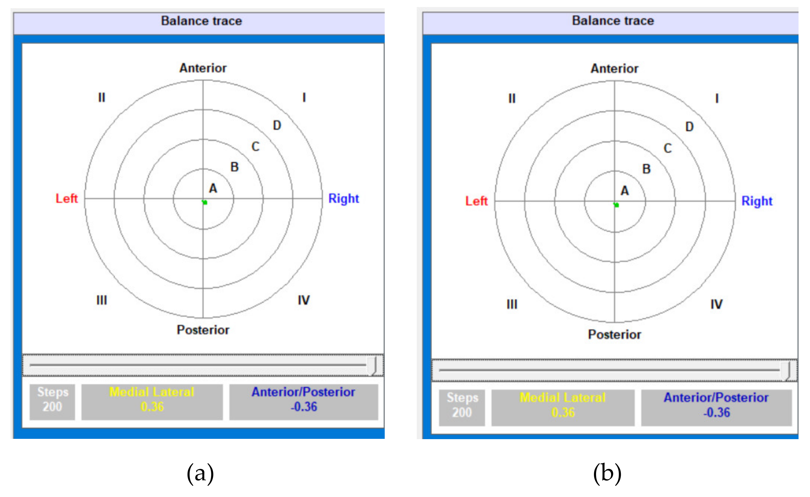
| Test Number | Medial Lateral (X axis) (°) | Anterior/Posterior (Y axis) (°) |
|---|---|---|
| 1 | 0.36 | –0.36 |
| 2 | 0.36 | 0.49 |
© 2020 by the authors. Licensee MDPI, Basel, Switzerland. This article is an open access article distributed under the terms and conditions of the Creative Commons Attribution (CC BY) license (http://creativecommons.org/licenses/by/4.0/).
Share and Cite
Orozco-Magdaleno, E.C.; Cafolla, D.; Castillo-Castaneda, E.; Carbone, G. Static Balancing of Wheeled-legged Hexapod Robots. Robotics 2020, 9, 23. https://doi.org/10.3390/robotics9020023
Orozco-Magdaleno EC, Cafolla D, Castillo-Castaneda E, Carbone G. Static Balancing of Wheeled-legged Hexapod Robots. Robotics. 2020; 9(2):23. https://doi.org/10.3390/robotics9020023
Chicago/Turabian StyleOrozco-Magdaleno, Ernesto Christian, Daniele Cafolla, Eduardo Castillo-Castaneda, and Giuseppe Carbone. 2020. "Static Balancing of Wheeled-legged Hexapod Robots" Robotics 9, no. 2: 23. https://doi.org/10.3390/robotics9020023
APA StyleOrozco-Magdaleno, E. C., Cafolla, D., Castillo-Castaneda, E., & Carbone, G. (2020). Static Balancing of Wheeled-legged Hexapod Robots. Robotics, 9(2), 23. https://doi.org/10.3390/robotics9020023