Abstract
In this paper, an investigation is presented that demonstrates the application of a new approach for enabling the reduction of liquid slosh by implementing optimized motion profiles over a continuous range of operating speeds. Liquid slosh occurs in the packaging process of beverages. Starting by creating a dynamic process model, optimal control theory is applied for calculating optimal motion profiles that minimize residual vibration. Subsequently, the difficulty of operating speed dependency of the herewith synthesized motion profiles is examined. An approach in which the optimal motion profiles are consolidated into a characteristic map of motion specifications, which can be executed by a programmable logic controller in real time, is discussed. Eventually, the success of this novel approach is demonstrated by the comparison with state-of-the-art motion profiles and conventional motion implementation.
1. Introduction
Packaging machines are used in various areas of the consumer goods production industry. They are developed with the aim of packaging everyday products such as food, beverages, and pharmaceuticals. In order to meet the worldwide demand for consumer goods, packaging machines are operated with the intention of a maximum machine output [1] at each desired operating speed. The achievement of this objective is made more difficult by restrictions that often result from the behavior of the material to be packaged, rather than from the mechanical or the mechatronical machine assemblies. One possibility that can continue to increase the machine output is the deployment of parallel working machines; however, this would be associated with increased investment and operating costs. One opportunity that machine developers have is the optimal adaption of the process control. An illustrative example, which is considered here, is the intermittent transport of liquids, whose abstracted process depiction is displayed in Figure 1.
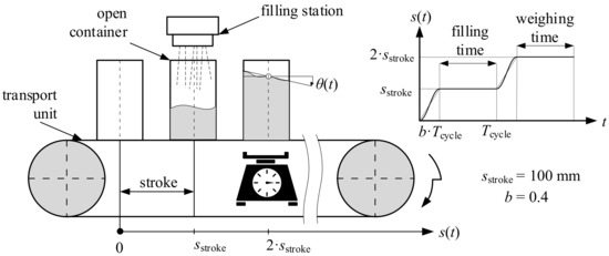
Figure 1.
Schematic illustration of the underlying practical problem in packaging machines: An empty container is intermittently conveyed to a filling station, filled with liquid, and afterwards transported to a weighing station. To realize a valid weighing result, it is important to achieve as little residual vibration of the liquid’s surface as possible. In this study, a conveying stroke of mm, a ratio of motion time to cycle time of , and operating speeds up to 60 1/min are treated.
In pharmaceutical applications, liquids are conveyed intermittently in containers, whereby one machine cycle is used for filling and the subsequent machine cycle is used for the accurate weighing of the filled fluid. Due to the necessary space requirements of the individual assemblies, there must be a distance between the filling and weighing station. Between these stations, the container filled with fluid has to be conveyed. The problem that results out of this kind of process conducting is that, with increasing operating speed, the machine’s output theoretically increases too. In practice, the process cannot be implemented at any operating speed due to the resulting fluid liquid slosh that disables accurate weighing. Therefore, one possibility that machine designers can pursue is the optimization of conveying motion to prevent liquid sloshing, even at high operating speeds. This paper provides some novel aspects to be considered in the implementation of optimal motion profiles with modern motion control systems. In particular, the dynamic process behavior and the resulting optimal motion profile’s operating speed dependency is considered. For handling this, solutions are introduced, and their effectiveness is shown both with a computer model as well as experimentally with a physical model on a test station.
The problem of dynamical liquid slosh behavior induced by transporting dates back to the 1960s during aerospace research [2,3]. Based on this initial work, further investigations followed both in the field of modeling liquid slosh behavior, e.g., in [4] or [5], and in the field of motion optimization. An often applied approach for motion optimization is optimal control theory, which was used in [6,7]. In these works, special attention was paid to the formulation of different cost functionals and their effect on the optimization result. While [6] limited the investigations to computer simulation, [7] investigated the optimized motion profile’s effect on physical models too. Furthermore, the -theory was additionally applied to increase the motion’s robustness in [8]. In [9,10], optimal control theory was used to implement an optimal closed-loop feedback controller in order to minimize the liquid slosh. Hereby, it must be mentioned that a closed-loop feedback controller requires appropriate measurement possibilities of the process state values. This is hardly realizable in a real production process of packaging machines due to the requirements of hygienic design, accessibility, and, eventually, costs. For the sake of completeness, it should be mentioned that motion optimization aiming to implement a slosh-free process behavior is not limited to one-dimensional motion. Instead, in [11,12], it was shown that multi-dimensional trajectories can realize slosh-free behavior. However, in addition, very simple motion profiles synthesized without optimization, consisting only out of acceleration pulses, can lead under some considerations to slosh-free behavior [13]. Nowadays, even leading motion control producers have implemented modules that enable slosh-free conveying [14], which underlines the practical importance of the considered example.
Due to the effectiveness of optimal control theory, this tool will be applied here, whereby special attention is paid to the optimal motion’s resulting operating speed dependency. This property is essential for the real operation circumstances of packaging machines because packaging machines have to fulfill quality criteria for each targeted operating speed. Hence, a question arises as to how optimal pre-calculated motion profiles, which differ concerning their planned operating speed, can be implemented with modern servo drives, if no closed-loop-control system can be applied due to the reasons mentioned above. Therefore, an approach that uses optimal pre-calculated motion profiles for specifically chosen operating speeds and that interpolates these specifications for the application of other operating speeds in real-time is experimentally investigated here. Hence, no closed-loop feedback system is necessary, but it must be shown that all quality requirements are still satisfied.
2. Materials and Methods
2.1. Experimental Setup and Data Evaluation
In order to investigate the liquid slosh reacting to a motion profile, an experimental test station is applied, displayed in Figure 2. In essence, the station is composed of a linear direct drive that is controlled by programmable logic controller (PLC) of type BECKHOFFmathsizesmall TWINmathsizesmallCAT3 with a cycle rate of 8 kHz. A model container filled with liquid can be mounted to the drive, whereby, due to the high drive system’s dynamic stiffness, an accurate realization of the motion profile is possible. Furthermore, the container is constructed with stiff walls. Thus, the liquid’s behavior has no effect on the container, and the motion control system and hence an absence of retroactivity can be assumed. In addition, a high-speed camera and an LED light is fit to the setup. The high-speed camera records frames induced by trigger pulses that are sent by the PLC. Hence, the system input is synchronized with the measured output. This enables a precise evaluation of the gathered data. The recording frame rate (FR) adaptively results from the operating speed n. Hence, the number of recorded and frames to be analyzed is independent of the observed operating speed. The liquid’s surface is analyzed frame by frame by firstly setting a region of interest, secondly binarizing the image with a suitable threshold value, and thirdly deriving the surface’s edge and approximating a straight line with slope . The determination of this deflection is part of a data compression that facilitates the process modeling.
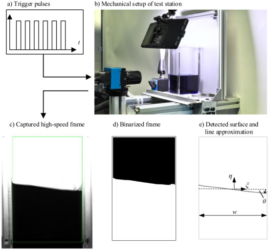
Figure 2.
Procedure of measuring a liquid’s slosh surface: A container is filled with colored water (volume’s dimensions: width w = 40 mm; hecight h = 67 mm; depth d = 60 mm) and coupled to a direct linear drive (b). The drive is controlled by a PLC, which also sends trigger pulses (a) to the high-speed camera, wherefore the captured frames are synchronized to the motion profile. After setting a region of interest to the captured frames (c), the frame is binarized (d), which eventually leads to the detection of the liquid surface and line approximation (e).
For evaluating the motion profile’s influence on the residual vibration, the effective value of the fluid’s vertical displacement during the dwell phase is defined as follows for each experiment:
In order to assess the effect of the optimal motion profile and the applied motion control principle over a continuous range of operating speeds, two more characteristic values are introduced, and they are additionally evaluated in this paper for each investigation: first, the mean value of the effective residual vibration over all operating speeds, and, second, the corresponding maximum value .
2.2. Process Modeling Taking into Account the Operating Speed
A necessary condition for a successful motion optimization in which the process is considered is the availability of a process model in a suitable form. A common model approach, e.g., used before in [4,6,7], is the mechanical pendulum, which is applied in the following. The underlying idea is that the interaction of the conveyed fluid and the moved container is a dynamical system, represented as an ordinary differential equation (ODE) that can be described by an input, an output, a system equation, and suitable model parameters. It has to be mentioned that this model approach is a very strong simplification and only applicable in a limited range of operating speeds in which the system’s first natural frequency is prevalent.
The system equation of the mechanical pendulum model is defined as follows:
Herein, describes the damping ratio, represents the undamped natural frequency of the system, and g is the gravitational acceleration.
The rectangular acceleration pulse motion profile, whose definition is displayed in Equation (3), is used as a system input for operating speeds ranging from 12 to 60 1/min with the aim of identifying the model’s parameters. For each operating speed, an experiment is carried out 10 times, and the associated fluid surface values are evaluated for obtaining the approximated slope regime . These experimental results are used for deriving optimal model parameters , which reproduce the system behavior for all investigated operating speeds in the most suitable way. This is done by solving a least-square problem in which the gradient-based LEVENBERG–MARQUARDT algorithm minimizes the residuals between the simulated and measured state values, taking into account all experiment repetitions at once. This ensures a high model quality and minimizes the influence of measurement outliers and measurement uncertainties:
For the considered container and fluid geometry, the best accordance between measured and simulated system output is achieved for model parameters rad/s and .
In Figure 3, two exemplary system inputs as well as the measured and simulated outputs are displayed for two investigated operating speeds. There is no high variance in the experimental results, wherefore the motion profile’s robustness is not discussed here. Moreover, the simulated system outputs fit the measured results in a satisfactory way. Therefore, the derived model approach in combination with the identified optimal model parameters and are used in the following.
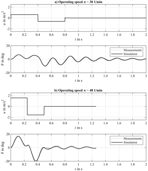
Figure 3.
Illustration of the system input in the form of the motion’s profile acceleration graph, the experimentally derived system’s answer, and the corresponded simulation responses for an operating speed of 30 1/min (a) and 48 1/min (b).
It should be noted that the experiments additionally show that a motion profile with a maximum absolute acceleration value higher than 2.5 m/s violates the approach of considering the fluid surface as a straight line. Therefore, the acceleration is limited correspondingly in the following motion optimization.
2.3. Motion Optimization with Optimal Control Theory Considering the Operating Speed Dependency
Regarding the discussed requirements of the process behavior at the beginning of this paper, the aim is to synthesize a horizontal container motion profile that minimizes the residual vibration of the transported fluid and implements the claimed stroke in the demanded time. Optimal control theory [15] deals with the synthesis of trajectories for the controlling dynamical systems under consideration of specific conditions and with the aim of minimizing a cost functional. Considering the limited time horizon and defining a control variable and the state vector , the problem to be solved can be formulated generally as follows:
being subject to
Hereby, describes the system dynamics. Applying PONTRJAGINmathsizesmall’s maximum principle [16], these demands lead analytically to a boundary value problem (BVP), which yields the optimal control trajectory. This strategy, often mentioned as an indirect approach, is only expedient for some special cases. Therefore, numerical approaches are common for solving such problems, which do not aim to solve necessary conditions. Instead, the continuous optimization problem is transferred to a static problem with a finite number of optimization variables. This strategy is called the direct approach [17]. In the following, the direct collocation method with quadratic trial functions is applied [18]. Thereby, the dynamic optimization problem is transferred to a static problem by discretization of the time domain as well as of the control and state variables.
Considering the process model , derived in Section 2.2, setting the state variables , , , and the motion’s profile acceleration as the control variable leads to the following first order system of differential equations:
The boundary conditions, resulting from the process requirements, are given by
These conditions enforce the adherence of the motion’s requirements and demand zero residual vibration during the motion’s dwell phase. In addition, the control variable is limited during the motion phase, since the validity of the model is limited to an maximum acceleration of 2.5 m/s and is set to zero during the dwell phase:
Eventually, the cost functional aims to minimize the control effort and is given by
Thus, the optimization problem to be solved is fully described by Equations (5)–(8). Applying the collocation method, this problem is solved with discrete time steps. Hence, the static optimization problem consists of 3005 free parameters and 2400 equality constraints, which is numerically solved by the open-source library IPOPT [19]. In Figure 4, three optimal motion profiles depending on the targeted operating speed are displayed. For each optimal motion profile, the corresponding model response is additionally illustrated. The optimization was successful in each case due to the zero residual vibration of the model response and due to the adherence of all boundary conditions stated to the motion profile.
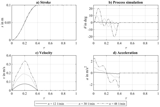
Figure 4.
Stroke (a), velocity (c), and acceleration (d) graphs of the optimized motion specifications resulting from solving the corresponding optimal control problems for three different operating speeds. The simulated model responses are also displayed (b). Obviously, no residual vibration is achieved, which must be why the optimization was successful. For a better comparison, the motion profiles are displayed over their normalized time .
2.4. Implementation of Operating Speed Dependent Motion Profiles
It is obvious that the resulting optimal motion profiles displayed in Figure 4 are not scalable to each other, as it is expected from classical motion profiles. Instead, an operating speed dependency is observable, which leads to the question of how these profiles can be executed on a motion control system. In order to face this difficulty, the way in which the process behaves if only one optimal motion profile is applied and implemented with a state-of-the-art motion control approach should be initially discussed. Thereby, the motion profile’s stroke, velocity, and acceleration specifications are provided for one operating speed. If another operating speed is considered, the PLC provides the specification by scaling the motion to the specific operating speed. Figure 5 shows the simulated residual vibration of the fluid over the investigated range of operating speeds for this approach. Thereby, three different operating speeds are considered for which the optimized motion profile is provided.
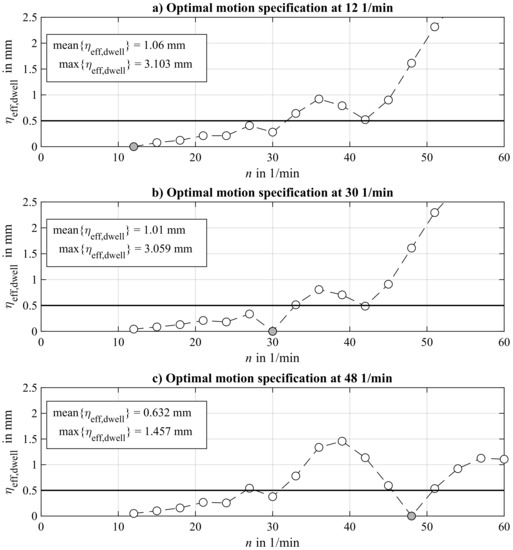
Figure 5.
Process simulation for applying one optimal motion profile that is optimized for a specific operating speed and scaled to other operating speeds. Three results, which differ in the operating speed for which the motion profile is optimized, are displayed: 12 1/min (a), 30 1/min (b), and 48 1/min (c).
As can be seen in Figure 5, the residual vibration is expectably zero at those operating speeds for which the motion profile is optimized. When the motion profile is scaled to other operating speeds, the optimization loses its effect and the residual vibration increases. This coherence occurs in all investigated cases, whereby the effect of the operating speed dependency varies with the operating speed for which the motion profile was optimized, as can be seen in Figure 5. Assuming that due to process quality requirements should be less than 0.5 mm, a usable range of operating speeds can be derived for applying the specific motion profile. The aim is to ensure that this range is coherent so that the machine can be operated at any speed.
Therefore, this state-of-the-art approach of implementing optimized motion profiles without using closed-loop-feedback controllers cannot fulfill necessary process quality criteria for a continuous range of operating speeds. Due to the necessity of conducting packaging machines at any feasible operating speed, the operating speed dependency of the optimized motion profiles has to be considered.
One approach of implementing operating-speed-dependent motion profiles in real time was firstly presented in [20] and as a result experimentally applied in [21]. The aim is to enable the provision of motion specifications for any targeted operating speed without executing the optimization in real time.
It is assumed that there is a set of chosen operating speeds with for which optimal motion profiles are pre-calculated. The optimal motion profiles are placed at one’s disposal in form of their path-, velocity-, and acceleration-profile . Considering that the PLC must provide a motion specification at the targeted operating speed , one can distinguish between two main concepts of implementing the operating speed dependency:
Discrete Execution with Scaling Principle:
- Step 1:
- Determine the index of the operating speed for which an optimal motion profile specification exists that is closest to the target operating speed:
- Step 2:
- Calculate the motion specification for the desired operating speed by scaling as follows:
The output obtaining this approach is illustrated in Figure 6 for considering two and three optimal motion profiles. It is obvious that there are discontinuities in the resulting characteristic map of the velocity specifications. In the real production process, these discontinuances may lead to undesired vibration effects that could decrease the machine’s output. Hence, this approach is not expedient for controlling dynamical processes, despite its outstanding simplicity.
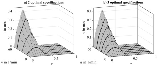
Figure 6.
Discrete execution of operating-speed-dependent motion profiles for two (a) and three (b) optimal specifications whereby each motion profile is scaled proportional to the operating speed. Exemplarily, the characteristic map of the velocity is displayed with obvious discontinuities.
Continuous Execution with Linear Interpolation:
- Step 1:
- Determine the index of the operating speed for which an optimal motion profile specification exists that is closest to the target operating speed:
- Step 2:
- Step 3:
- Otherwise, determine the index of the operating speed for which an optimal motion profile specification exists that is second closest to the target operating speed:
- Step 4:
- Derive the necessary values:
- Step 5:
- Calculate the motion specification for the desired operating speed by interpolation as follows:
The output of applying this approach is displayed in Figure 7, considering two and three optimal motion profiles. In contrast to the previous approach, no discontinuities occur in the characteristic map of the velocity specifications. This property allows the application of the continuous execution approach over a coherent range of operating speeds in the real production process.
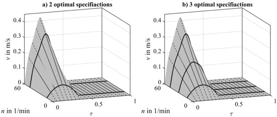
Figure 7.
Continuous execution of operating-speed-dependent motion profiles for two (a) and three (b) optimal specifications by linear interpolation in the direction of the operating speed. Obviously, no discontinuities occur in the characteristic map.
Determining a Suitable Distribution of Optimal Motion Profile Specifications
In order to apply the continuous execution principle, how large the number of optimal motion profile specifications to be considered should be and how they should be distributed remain unknown. Once a valid process model is available, this question can be answered. Figure 8 displays an algorithm that systematically investigates all possible distributions of optimal motion specifications for a given number K of specifications to be considered and N possible operating speeds, at which they can be distributed.
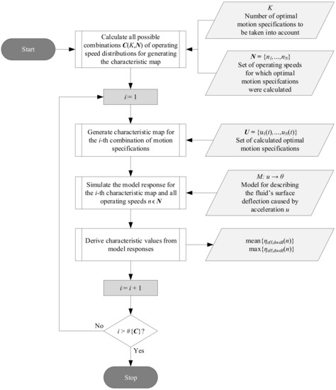
Figure 8.
Algorithm for evaluating all possible distributions of optimal motion specifications to generate a characteristic map for a given set of operating speeds and number K of motion specifications to be considered. For each generated map, the characteristic values are evaluated from a simulation run.
Figure 9 illustrates the simulated process behavior over the investigated range of operating speeds for two possible distributions of optimal motion specifications during the execution of the presented algorithm. Thereby, two optimal motion profiles are considered. In order to enable a comparison between the simulated results, the process behavior has to be evaluated. Therefore, the two characteristic values and are calculated for each considered distribution.
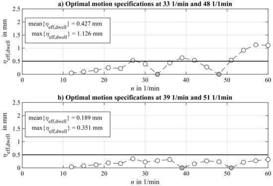
Figure 9.
Exemplary results of simulated model responses considering two different characteristic maps regarding two optimal motion specifications: Case (a) considers optimal motion profiles at operating speeds 33 and 48 1/min; Case (b) considers optimal motion profiles at operating speeds 39 and 51 1/min. The measure for evaluating the residual vibration is displayed for the same range of operating speeds. Solutions that result from operating speeds at which optimal specifications have been considered are highlighted and are expectably zero.
3. Results
3.1. Experimental Results Applying Standard Motion Profiles
In order to estimate the success of the optimal motion profiles and their continuous linear interpolated implementation of operating speed dependency, at first a benchmark has to be performed. Therefore, two standard motion profiles, as they are provided in each purchasable motion control system, are applied—namely, the rectangular pulse acceleration motion profile and a 5th order polynomial motion profile. The main differences are that the rectangular pulse motion profile has a constant absolute value of acceleration and, in addition to that, contains three acceleration steps.
In Figure 10, the results of applying these two motion profiles to the observed container filled with fluid over the investigated range of operating speeds are illustrated. In order to obtain a better impression, the value depicting the residual vibration during the dwell phase is evaluated.
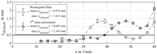
Figure 10.
Experimental results by applying the rectangular pulse motion profile and a 5th order polynomial motion profile for operating speeds n ranging from 12 to 60 1/min. The characteristic value is a measure for the residual vibration of the fluid surface.
Assuming a tolerable maximal residual effective value of the liquid slosh of 0.5 mm leads to a usable range of operating speeds for the specific motion profile. The quintic polynomial motion profiles exceeds the tolerable value at an operating speed of 39 1/min. Thus, 65% of the investigated operating speed range is applicable. In contrast, the rectangular pulse acceleration motion profile crosses the tolerable value three times, namely at operating speeds of 30, 47, and 56 1/min. This leads to a cumulative range of usable operating speeds of 39 1/min, which is the same as that when applying the quintic polynomial motion. However, it should be noted that the maximal realizable operating speed is higher than it is when implementing the polynomial motion. Furthermore, the mean and maximal parameters of the derived effective values are depicted in Figure 10. This enables a better comparison between the effectiveness of the different motion profiles.
3.2. Determining a Suitable Distribution of Optimal Motion Profile Specifications
Applying the algorithm presented in Section 2.4 leads to possible distributions of optimal motion profile specifications. To enable a better comparison, both the mean as well as the maximal value of the simulated residual vibration is calculated for each considered distribution. Thereby, the derived solutions are classified into feasible and non-feasible solutions. Due to the requirements already discussed, the maximum value should be less than 0.5 mm, and the mean value should be less than 0.3 mm. As several solutions are expected to fulfill these requirements and hence will be applicable, it is important to select the best of them. In order to identify the best solution, the two derived parameters are consulted to build an objective value, which is defined as the square of the EUCLIDEAN distance:
The results of these investigations are displayed in Figure 11 for considering the specification of one, two, three, and four optimal motion profiles. Obviously, no feasible solution can be achieved considering one specification. With an increasing number of considered optimal specifications, the number of possible solutions increases as well. The value of the incorporated objective value constructed in Equation (21) does not significantly rise with an increasing number of motion specifications. In addition, it can be stated that simulative results are obtained that, when the optimal motion profiles are implemented, provide even worse results than when the standard motion profiles are applied.
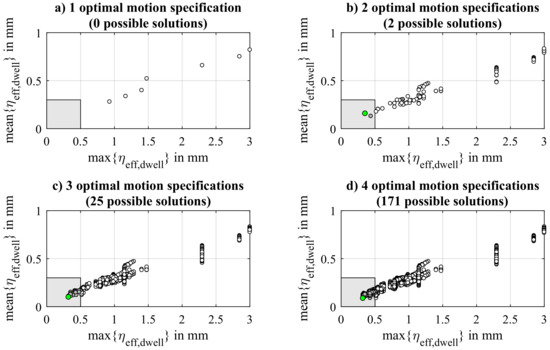
Figure 11.
Determining the best distribution of optimal motion profiles for different numbers of specifications. A solution is feasible, if the characteristic values are inside the gray rectangular box. From all solutions, the best solution, which exhibits the smallest distance to the origin, is chosen. One (a), two (b), three (c), and four (d) optimal motion profiles are considered.
Finally, considering the optimal distributions, Figure 12 shows the corresponded characteristic velocity maps. It is obvious that the optimal motion profiles are not equidistantly distributed. Furthermore, the minimum operating speed at which a specification is applied changes depending on the number of optimal specifications.
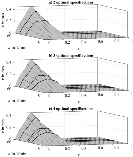
Figure 12.
Optimal characteristic velocity maps for two (a), three (b), and four (c) optimal motion profile specifications applying the continuous linear interpolation principle.
3.3. Simulative and Experimental Results Applying Optimal Characteristic Maps
The application of the characteristic maps displayed in Figure 12 finally leads to the experimental investigation of the effectiveness of the presented approach. Figure 13 depicts the simulative and experimental results for applying the identified best distributions for considering two, three, and four optimal specifications. The experiments on the test station were carried out five times in order to achieve statistical safety. Hence, in contrast to the simulated results, the experimental results are provided with their standard deviations.
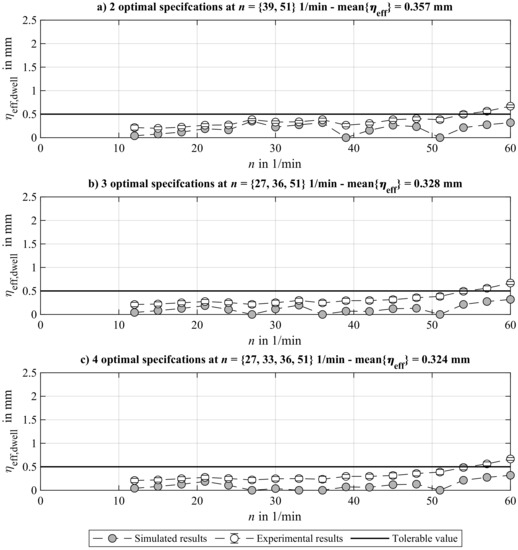
Figure 13.
Comparison of simulated and experimental results for applying linear interpolated and optimal operating-speed-dependent motion profiles for controlling liquid slosh. The measure for the residual vibration is displayed for different numbers of optimal motion specifications: two (a), three (b), and four (c) optimal motion profiles are considered for generating the characteristic map.
At first, the simulation results are observed. As expected, the simulated results show local minima at those operating speeds used to set an optimal motion specification. The associated experimental results display analogous behavior, whereby a systematical offset can be determined. The local minima at operating speeds for which optimal motion specifications are set are especially obvious at the experimental results. Furthermore, the trend of decreasing mean value of effective residual slosh with a rising number of motion specifications, already indicated by the simulated results, can also be obtained from the experiments. In contrast to the simulated results, the obtained experimental results show that the objective value cannot be set completely below the desired tolerance value over the entire range of investigated operating speeds.
Nevertheless, for 90% of the investigated range of operating speeds, the aim is achieved, which confirms an increase of almost 40% in contrast to applying standard motion profiles. Even better is the reduction of the maximal residual slosh occurring at an operating speed of 60 1/min. Regarding this, a reduction of 63% is achieved with the optimal motion profiles compared to when the rectangular acceleration pulse motion is applied, and even a reduction of 73% is reached in relation to the application of the quintic polynomial motion profile.
Regarding the mean value of , a reduction of 38% (considering two optimal motion specifications) and 43% (considering three and four optimal motion specifications) is notable in contrast to when the rectangular acceleration pulse motion is applied. Regarding the application of the quintic polynomial motion, the percentage reductions amount to 45% and 49%.
4. Discussion
The local minima observed for the residual slosh after applying the rectangular acceleration motion profile are due to the dynamic behavior of the process. The acceleration pulses and deceleration pulses generate phase-shifted vibrations, which cancel each other under specific circumstances. This effect is known as in-phase interception and is discussed in more detail in [13] for the observed example. Furthermore, the dynamic process behavior is decisive for the non-equidistant distribution of optimal motion profile specifications. In fact, a non-equidistant distribution is related to regions of high dynamic impact, which occurs within specific ranges of operating speeds. The location of this region is basically dependent on the system’s significant time constant, which is in this case the damped natural period, in relation to the motion time.
The obvious offset between measured and simulated results in Figure 13 can be explained by the simplified model approach of representing the fluid surface as a straight line. Hence, smaller waves on the surface are measured and evaluated, but are not considered in the model evaluation during optimization. In essence, this is the reason why the original aim of setting the objective below the desired tolerance is not achieved. Another obvious effect that has to be explained is the measured equal maximal value of for all considered numbers of optimal motion specifications. This is due to the fact that, for all distributions, the highest operating speed for which an optimal specification is made is identical, namely 51 1/min. Thus, considering the presented continuous interpolation principle discussed in Section 2.4, the optimal specification is only scaled to the targeted operating speeds and is thus independent from all other optimal specifications used in building the characteristic map.
The fact that only one optimal motion specification leads to no feasible solution, and that some profiles, compared to when standard motion profiles are applied, lead to worse results over the complete range of operating speeds, underlines the specificity of the synthesized motions. Standard motion profiles do not consider specific process behavior and hence do not achieve the same optimality at specific operating speeds, but are nevertheless a good compromise between simplicity and applicability. The benefit of model-based optimal motions can only be obtained if the operating speed specificity is considered, as it is in the investigation presented here.
5. Conclusions
The optimization of conveying motions considering a dynamic process model can be performed by applying optimal control theory. The resulting optimization problem can be solved by a direct approach such as the collocation method. Solving such a problem leads to operating-speed-dependent motion profiles. For realizing such motion profiles, a real-time implementation approach by building a characteristic map out of a specific number of optimal motions profiles was considered. How many and in what way these specifications have to be distributed was investigated. An algorithm was presented that automatically investigates all possible combinations and finds the best solution. Eventually, experimental results showed that a crucial increase in the usable range of operating speeds is possible when the presented method is applied. Furthermore, a significant reduction in the maximal residual slosh was obtained in comparison with the application of standard motion profiles. In future work, the problem of distributed model parameters will be incorporated by considering the motion’s robustness. Thereby, it will be investigated how suitable such robust motion profiles are for continuous linear interpolation in overcoming their operating speed dependency.
Author Contributions
C.T. was responsible for writing the original draft of the present paper, methodology, investigation, and visualization. The funding acquisition, review, and editing of the manuscript as well as the conceptualization was done by S.T. and J.-P.M. All authors have read and agreed to the published version of the manuscript.
Funding
These research results originate from the project Basics for the efficient use of multiaxial interpolating servo drives in processing machines, which was funded by the Deutsche Forschungsgemeinschaft (DFG) under Grant No. 182157057. The publication was subsidized by the Open Access Publication Fund of the TU Dresden.
Acknowledgments
The authors gratefully thank the Chair of Machine Tools Development and Adaptive Controls at the Technische Universität Dresden for lending the measurement equipment. Furthermore, the authors express their gratitude to the authors of the open-source library IPOPT for supplying their working results.
Conflicts of Interest
The authors declare that there is no conflict of interest. The funders had no role in the design of the study; in the collection, analyses, or interpretation of data; in the writing of the manuscript; and in the decision to publish the results.
Abbreviations
| BVP | Boundary value problem |
| FR | Frame rate |
| ODE | Ordinary differential equation |
| PLC | Programmable logic controller |
| Nomenclature | |
| Damping ratio | |
| Undamped natural angular frequency | |
| Identifier for process model | |
| Deflection of fluid surface | |
| Time derivative of fluid surface’s deflection | |
| Second time derivative of fluid surface’s deflection | |
| t | Time |
| State vector | |
| First time derivative of state vector | |
| Container’s conveyed stroke in one cycle | |
| b | Ratio of motion time to cycle time |
| Cycle time | |
| J | Cost functional |
| n | Operating speed |
| Local horizontal coordinate | |
| Measured fluid surface’s vertical displacement | |
| Effective value of during the dwell phase | |
| w | Fluid volume’s width |
| h | Fluid volume’s height |
| d | Fluid volume’s depth |
| d | Damping constant |
| g | Gravitational acceleration |
| s | Motion profile’s stroke |
| v | Motion profile’s velocity |
| a | Motion profile’s acceleration |
| u | Control variable |
References and Note
- DIN. DIN 8743: Packaging Machines and Packaging Installations, Time Related Definitions, Reference Factors and Calculation Fundamentals, 2007.
- Abramson, H.N.E. Dynamic Behavior of Liquids in Moving Containers with Applications to Propellants in Space Vehicle Fuel Tanks; Technical Report; NASA: Washington, DC, USA, 1966.
- Abramson, H.N.; Chu, W.H.; Kana, D.D. Some Studies of Nonlinear Lateral Sloshing in Rigid Containers. J. Appl. Mech. 1966, 33, 777–784. [Google Scholar] [CrossRef]
- Ibrahim, R.A. Liquid Sloshing Dynamics: Theory and Applications; Cambridge University Press: Cambridge, UK, 2005. [Google Scholar] [CrossRef]
- Kolaei, A. Dynamic Liquid Slosh in Moving Containers. Ph.D. Thesis, Concordia University, Montreal, QC, Canada, 2014. [Google Scholar]
- Dietze, S.; Schmidt, F.J. Entwurf zur Optimalsteuerung offener Behälter zum Fördern von Fluiden in Verarbeitungsmaschinen. arXiv 1997, arXiv:MATH-NM-13-1997. [Google Scholar]
- Grundelius, M. Methods for Control of Liquid Slosh. Ph.D. Thesis, Department of Automatic Control, Lund Institute of Technology, Lund, Sweden, 2001. [Google Scholar]
- Terashima, K.; Schmidt, G. Motion control of a cart-based container considering suppression of liquid oscillations. In Proceedings of the 1994 IEEE International Symposium on Industrial Electronics (ISIE’94), Santiago, Chile, 25–27 May 1994; pp. 275–280. [Google Scholar] [CrossRef]
- Hamaguchi, M.; Terashima, K.; Nomura, H. Optimal Control of Transferring a Liquid Container for Several Performance Specifications. Trans. Jpn. Soc. Mech. Eng. Ser. 1994, 60, 1668–1675. [Google Scholar] [CrossRef]
- Yano, K.; Yoshida, T.; Hamaguchi, M.; Terashima, K. Liquid Container Transfer Considering the Suppression of Sloshing for the Change of Liquid Level. Ifac Proc. Vol. 1996, 29, 701–706. [Google Scholar] [CrossRef]
- Feddema, J.T.; Dohrmann, C.R.; Parker, G.G.; Robinett, R.; Romero, J.V.; Schmitt, J.D. Control for slosh-free motion of an open container. IEEE Control. Syst. 1997, 17, 29–36. [Google Scholar] [CrossRef]
- Moriello, L.; Biagiotti, L.; Melchiorri, C.; Paoli, A. Manipulating Liquids with Robots: A Sloshing-Free Solution. Control. Eng. Pract. 2018, 78. [Google Scholar] [CrossRef]
- Troll, C.; Tietze, S.; Majschak, J.P. Investigation on the Application of Operating Speed Dependent Motion Profiles in Processing Machines at the Example of Controlling Liquid Slosh. In Advances in Mechanism and Machine Science; Uhl, T., Ed.; Springer International Publishing: Cham, Switzerland, 2019; pp. 1909–1918. [Google Scholar]
- Bosch Rexroth. How Adaptive Systems Unlock Big Producitivity Gains; Technical Report; Bosch Rexroth Group: Lohr am Main, Germany, 2014. [Google Scholar]
- Athans, M.; Falb, P.L. Optimal Control: An Introduction to the Theory and Its Applications; Dover Publications Inc.: McGraw-Hill, NY, USA, 2006. [Google Scholar]
- Pontryagin, L. Mathematical Theory of Optimal Processes; Classics of Soviet Mathematics; Taylor & Francis: Abingdon, UK, 1987. [Google Scholar]
- Bronstein, I.N.; Semendyayev, K.A.; Musiol, G.; Mühlig, H. Handbook of Mathematics; Springer: Berlin/Heidelberg, Germany, 2007; Volume 5. [Google Scholar]
- Betts, J.T. Practical Methods for Optimal Control and Estimation Using Nonlinear Programming, 2nd ed.; Society for Industrial and Applied Mathematics: Philadelphia, PA, USA, 2010; Volume 19. [Google Scholar] [CrossRef]
- Wächter, A.; Biegler, L. On the Implementation of an Interior-Point Filter Line-Search Algorithm for Large-Scale Nonlinear Programming. Math. Program. 2006, 106, 25–57. [Google Scholar] [CrossRef]
- Holowenko, O.; Kauschinger, B.; Ihlenfeldt, S. Increasing the Performance of Processing Machines by Executing Output Rate Dependent Motion Profiles. Int. J. Autom. Technol. 2017, 11, 165–170. [Google Scholar] [CrossRef]
- Troll, C.; Schebitz, B.; Majschak, J.P.; Döring, M.; Holowenko, O.; Ihlenfeldt, S. Commissioning new applications on processing machines: Part II – implementation. Adv. Mech. Eng. 2018, 10. [Google Scholar] [CrossRef]
© 2020 by the authors. Licensee MDPI, Basel, Switzerland. This article is an open access article distributed under the terms and conditions of the Creative Commons Attribution (CC BY) license (http://creativecommons.org/licenses/by/4.0/).