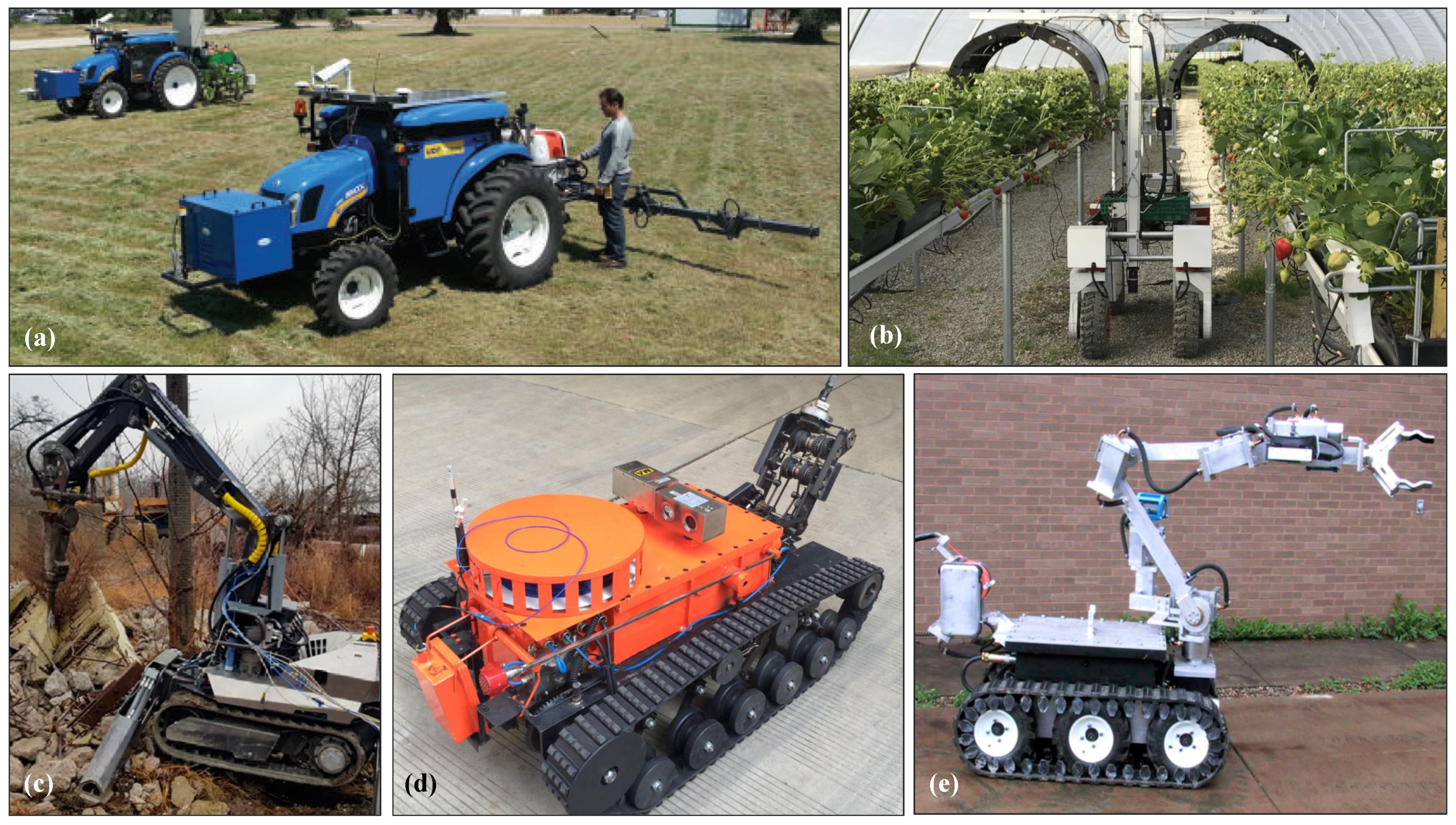
Figure 1.
Example field robotic platforms for (
a,
b) agriculture [
28,
29], (
c) construction and demolition [
40], (
d) search-and-rescue [
43], and (
e) working in explosive or hazardous environments [
46] (All figures originally published under CC-BY-4.0 license).
Figure 1.
Example field robotic platforms for (
a,
b) agriculture [
28,
29], (
c) construction and demolition [
40], (
d) search-and-rescue [
43], and (
e) working in explosive or hazardous environments [
46] (All figures originally published under CC-BY-4.0 license).
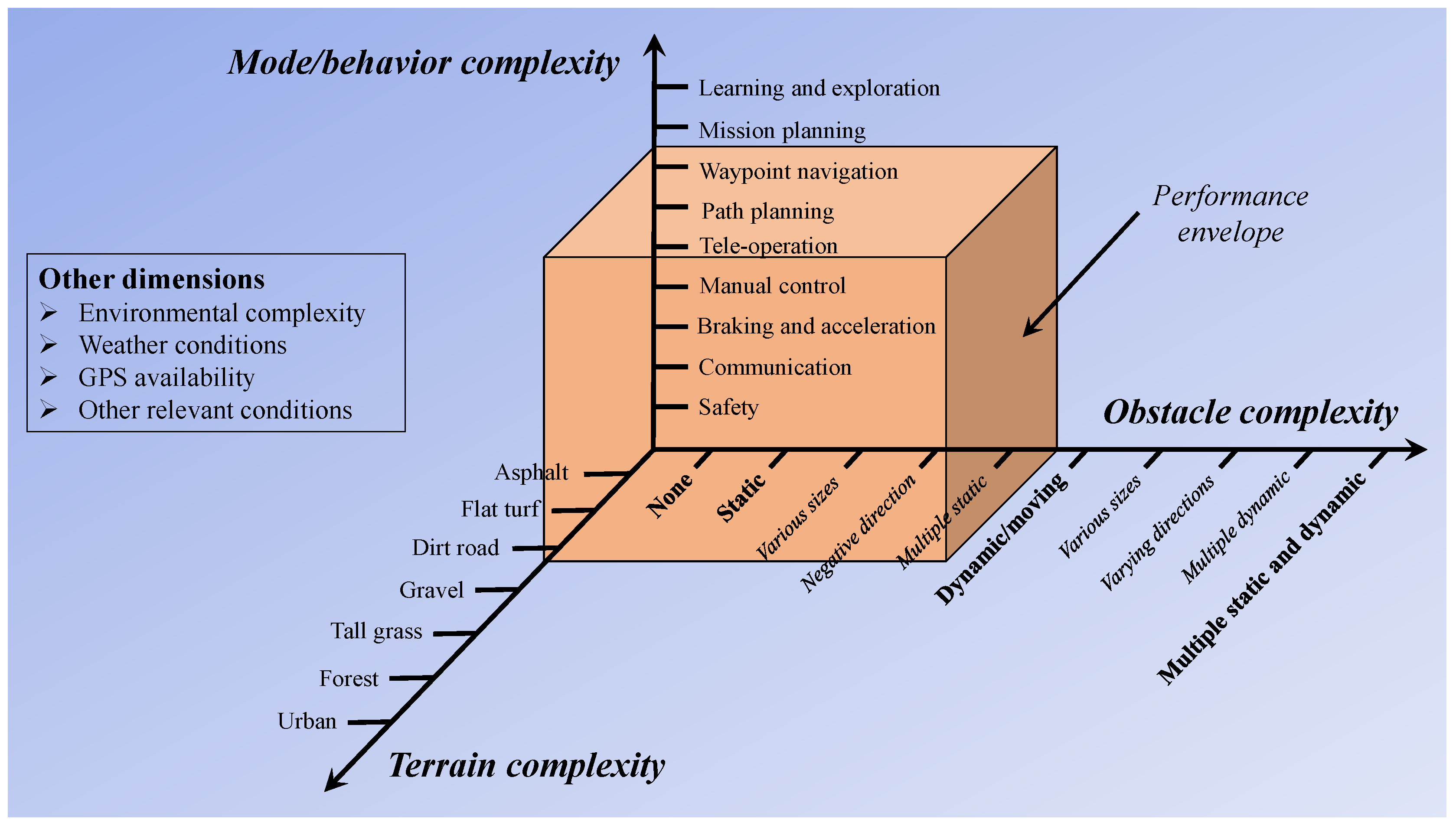
Figure 2.
Example application space complexity for mode, obstacle, and terrain complexity. Other dimensions may include environmental complexity, weather conditions, GPS availability, etc.
Figure 2.
Example application space complexity for mode, obstacle, and terrain complexity. Other dimensions may include environmental complexity, weather conditions, GPS availability, etc.
Figure 3.
Structure for developing the evaluation plan, beginning with definition of purpose and ending with a detailed procedure.
Figure 3.
Structure for developing the evaluation plan, beginning with definition of purpose and ending with a detailed procedure.
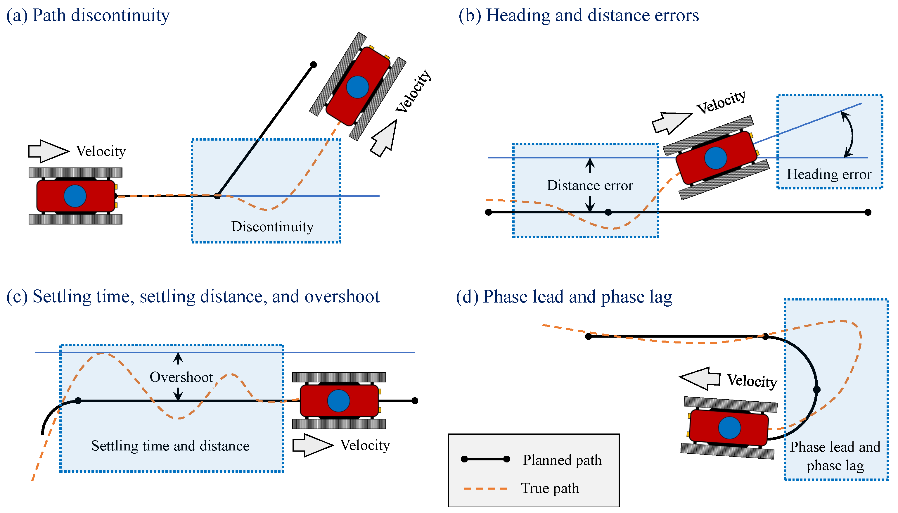
Figure 4.
Illustration of some qualitative parameters for system evaluation, (a) path discontinuities, (b) heating and distance errors, (c) settling time, settling distance, and overshoot, and (d) phase lead and phase lag.
Figure 4.
Illustration of some qualitative parameters for system evaluation, (a) path discontinuities, (b) heating and distance errors, (c) settling time, settling distance, and overshoot, and (d) phase lead and phase lag.
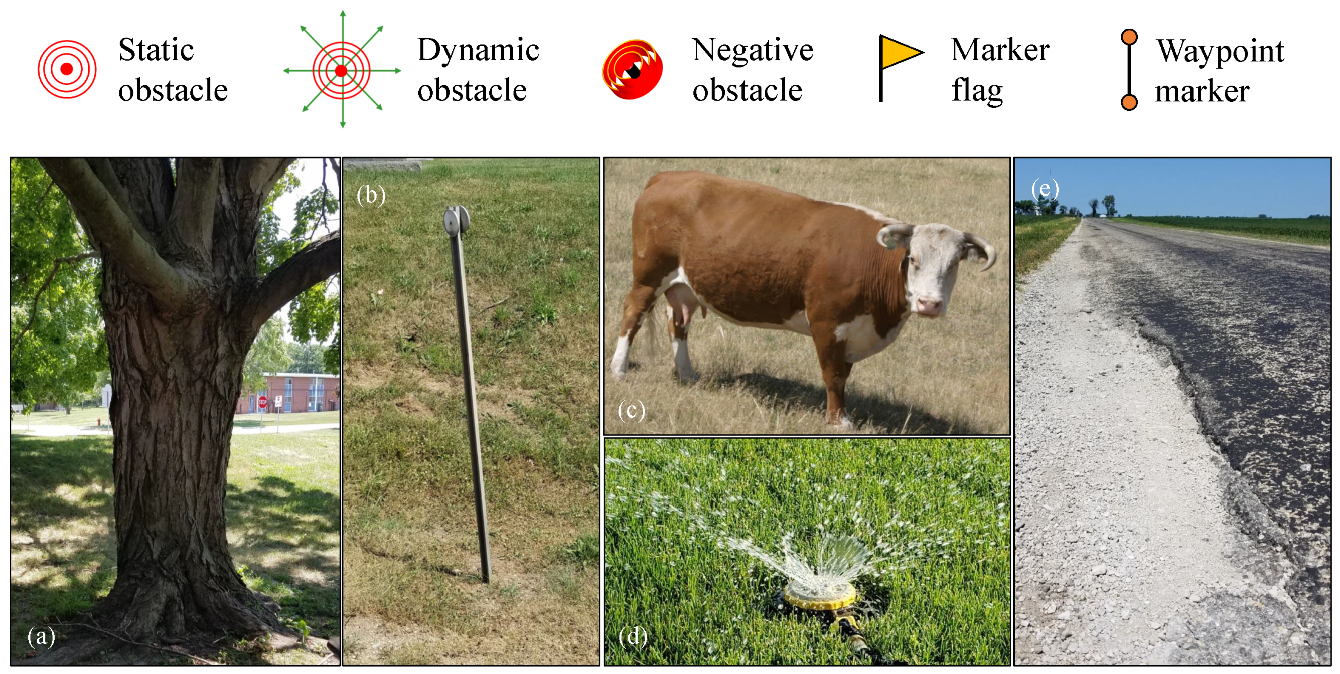
Figure 5.
Static, dynamic, and negative symbols, with flag marker for navigation and localization shown for further reference. Realistic examples of (
a) large obstacle which may block communication and interfere with navigation (large tree), (
b) simple static obstacle which does not interfere with navigation (driveway marker), (
c) mobile dynamic obstacle (animal) [
55], (
d) stationary dynamic obstacle (lawn sprinkler), and (
e) negative obstacle (road pothole).
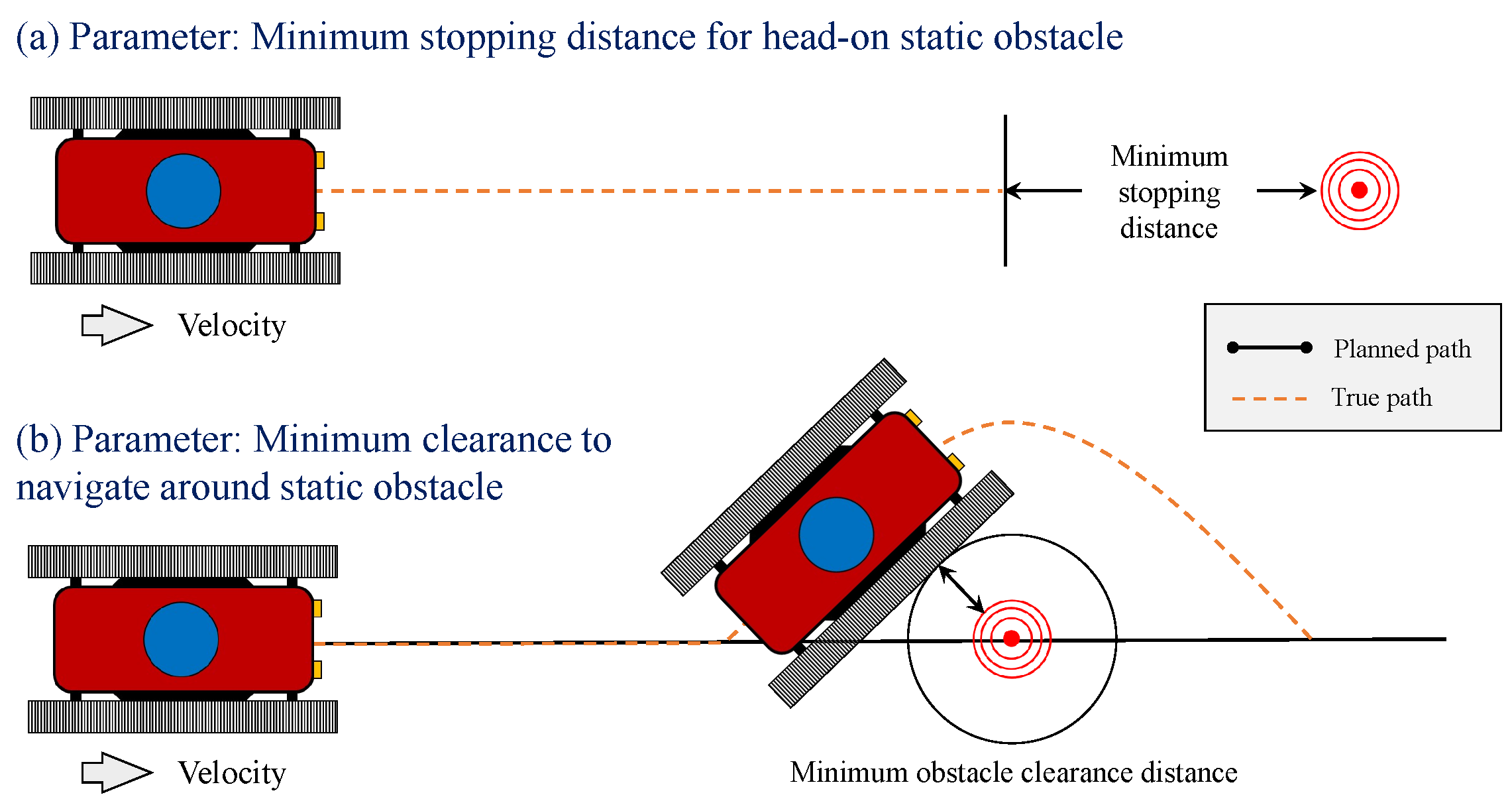
Figure 6.
Example vehicle navigation response behaviors to a simple static obstacle.
Figure 6.
Example vehicle navigation response behaviors to a simple static obstacle.
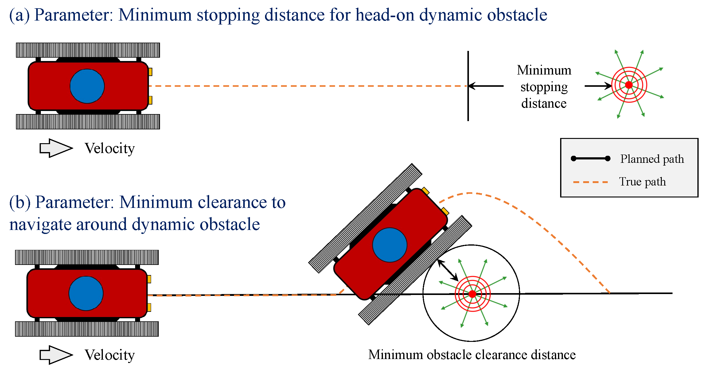
Figure 7.
Example vehicle navigation response behaviors to a simple dynamic obstacle.
Figure 7.
Example vehicle navigation response behaviors to a simple dynamic obstacle.
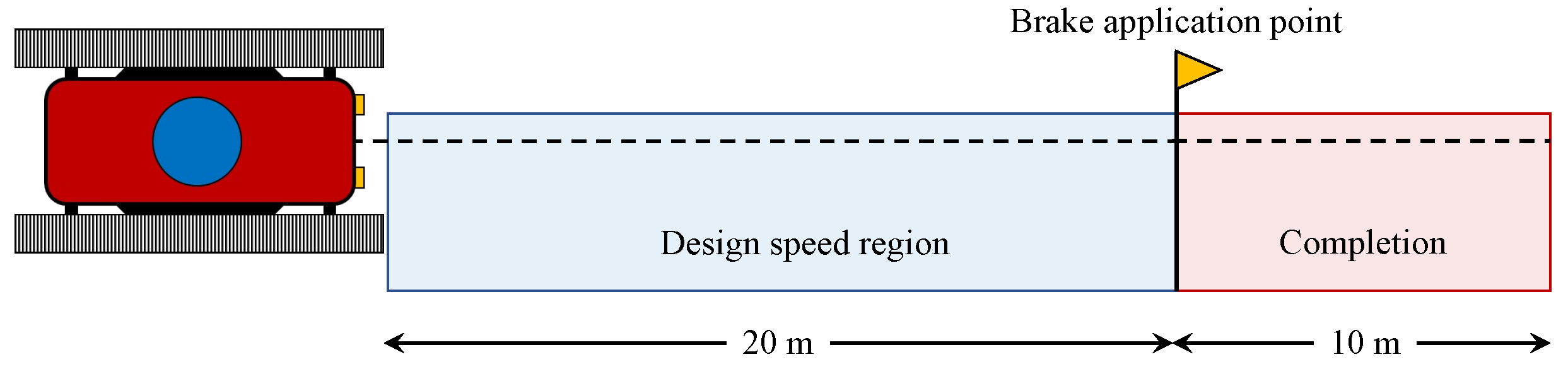
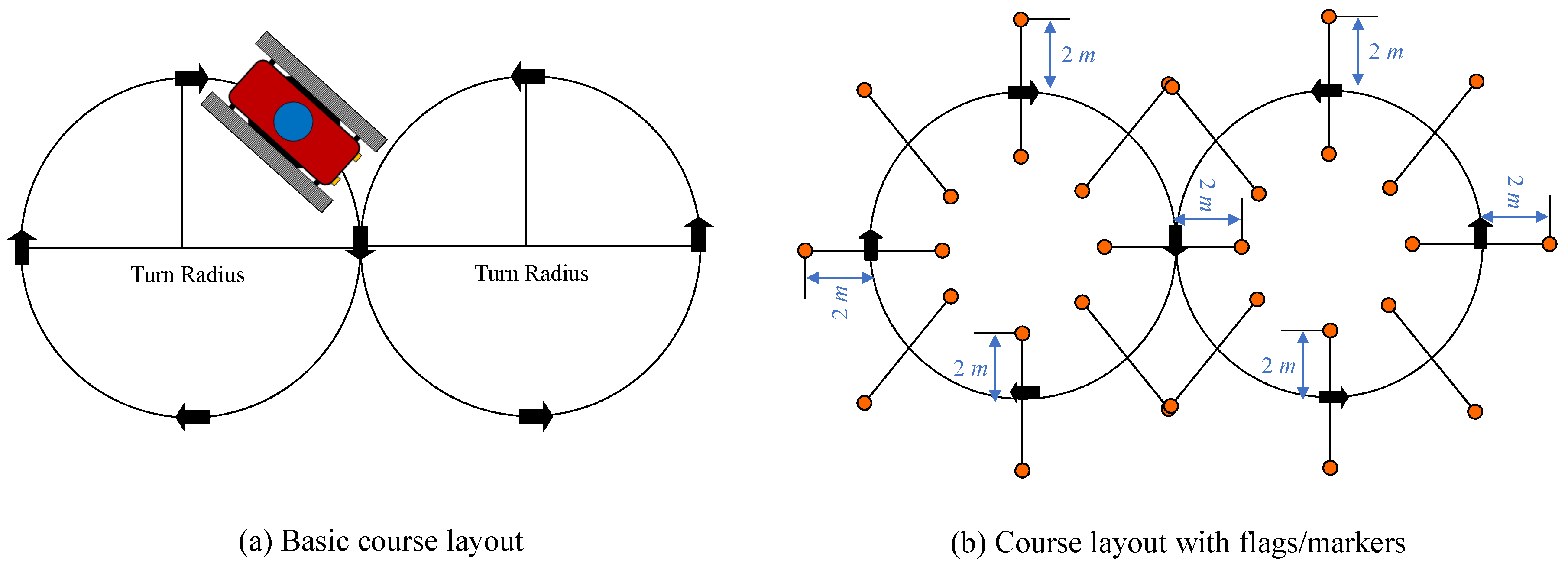
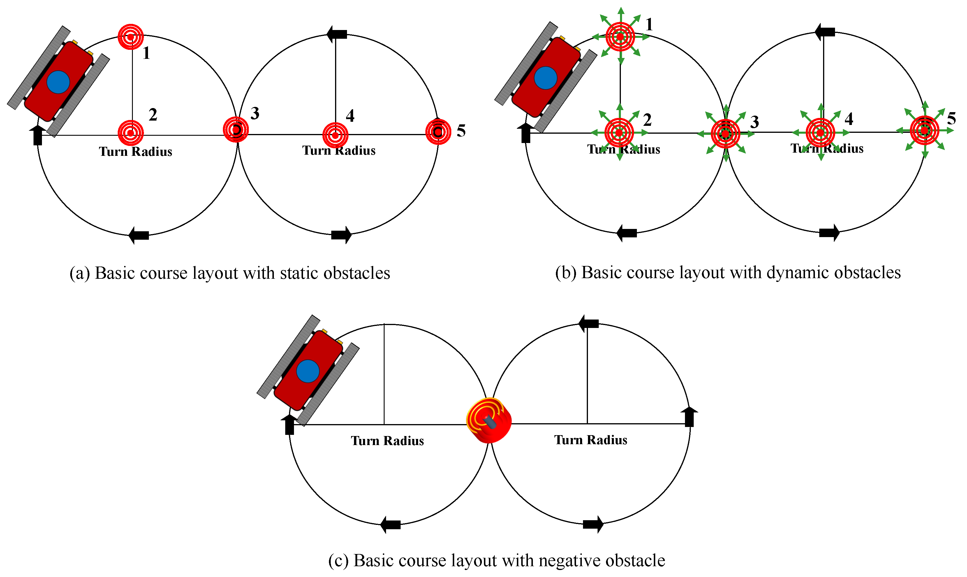
Figure 8.
Suggested test course for Safety Evaluation 1 (SE1).
Figure 8.
Suggested test course for Safety Evaluation 1 (SE1).
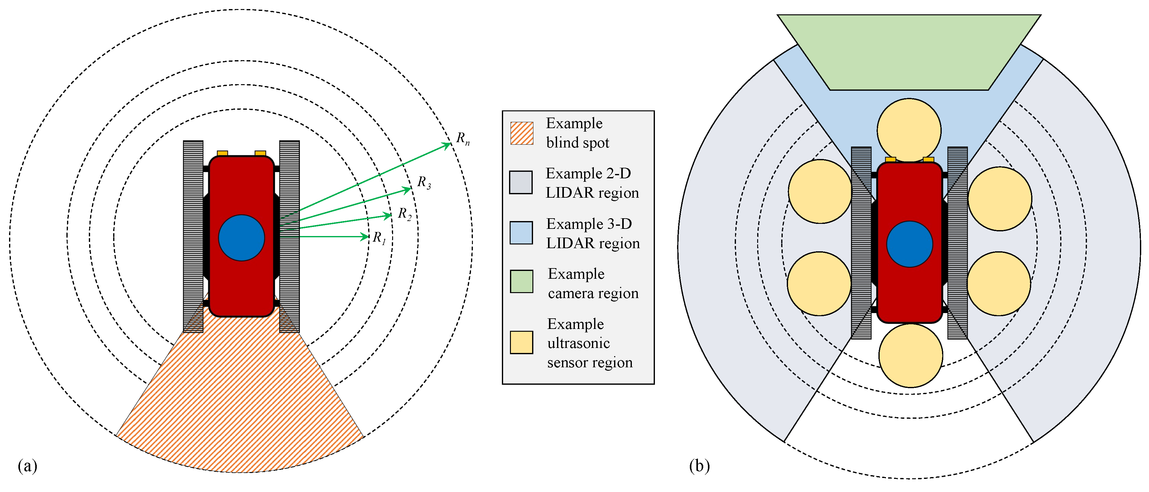
Figure 9.
Evaluation of (a) blind spots and obstacle distances, as well as (b) ranges and patterns for the instruments used to detect objects. Examples of 2D and 3D LIDAR, camera, and ultrasonic sensor ranges and patterns are given in (b).
Figure 9.
Evaluation of (a) blind spots and obstacle distances, as well as (b) ranges and patterns for the instruments used to detect objects. Examples of 2D and 3D LIDAR, camera, and ultrasonic sensor ranges and patterns are given in (b).
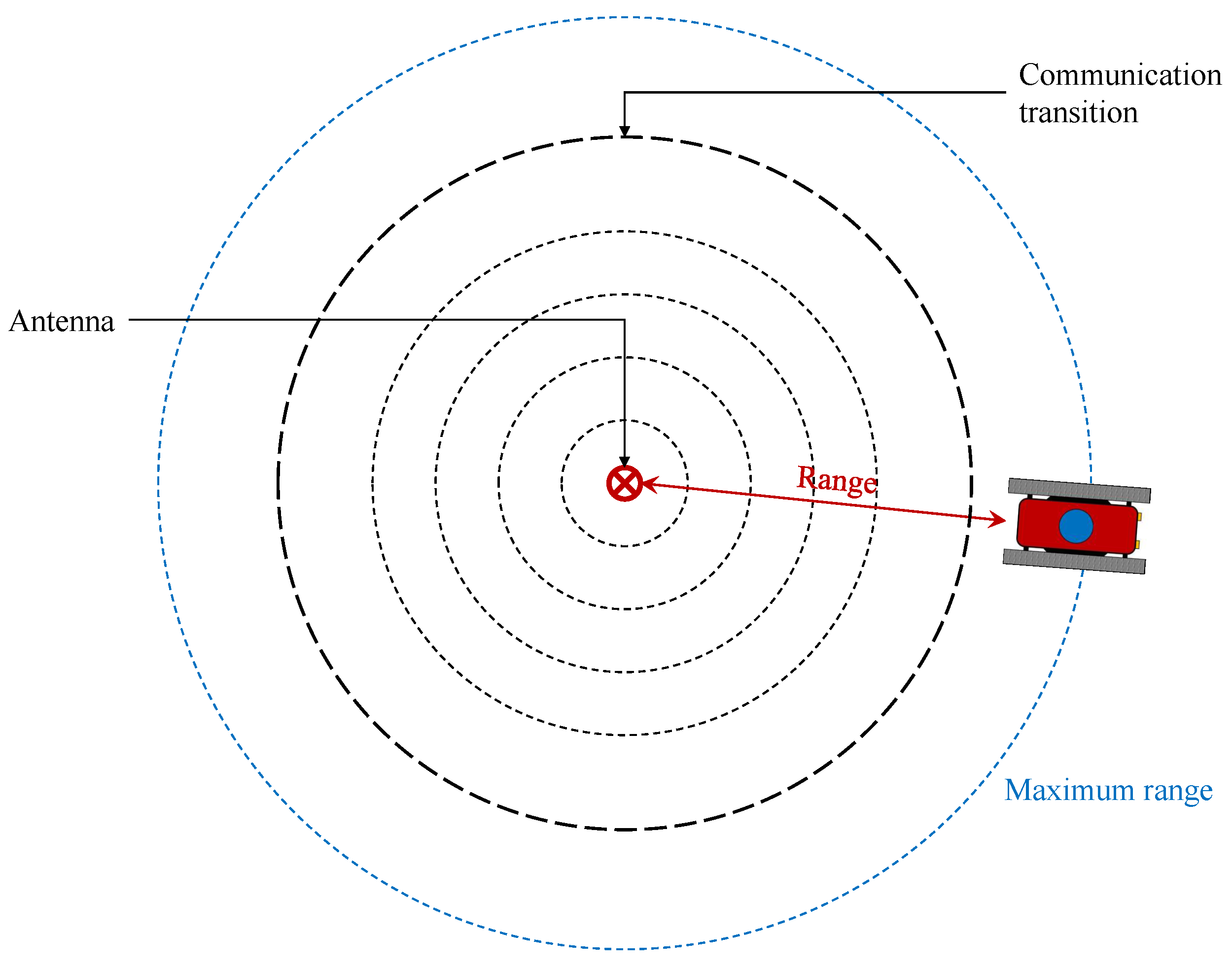
Figure 10.
Communication and range evaluation course example layout.
Figure 10.
Communication and range evaluation course example layout.
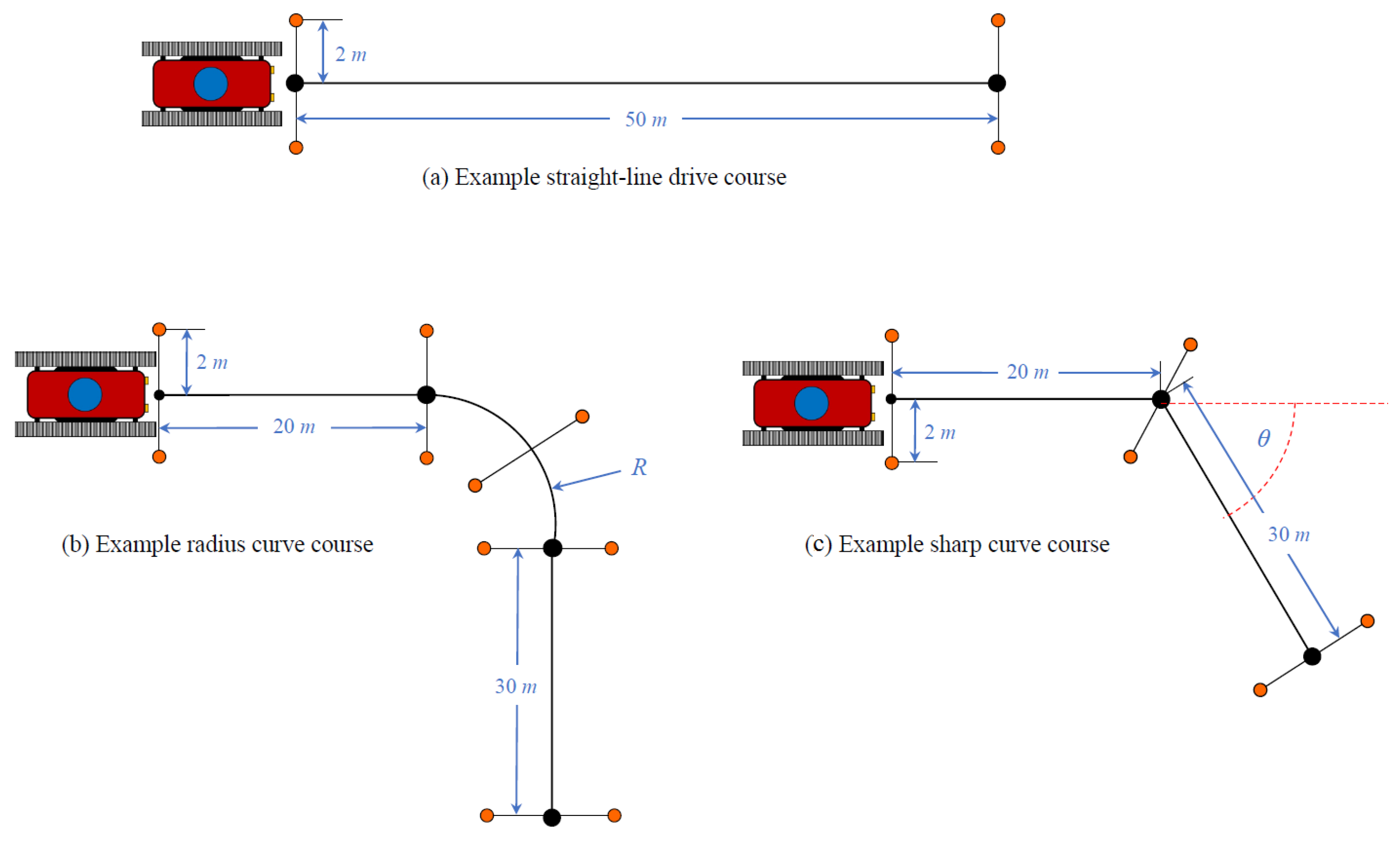
Figure 11.
Course layout for Behavior Evaluation 1, testing (a) straight-line, (b) curved turns, and (c) sharp turns for manual, SA/TO, and autonomous modes. The shown distances are for reference only and should be selected based on the design and requirements of the vehicle under evaluation.
Figure 11.
Course layout for Behavior Evaluation 1, testing (a) straight-line, (b) curved turns, and (c) sharp turns for manual, SA/TO, and autonomous modes. The shown distances are for reference only and should be selected based on the design and requirements of the vehicle under evaluation.
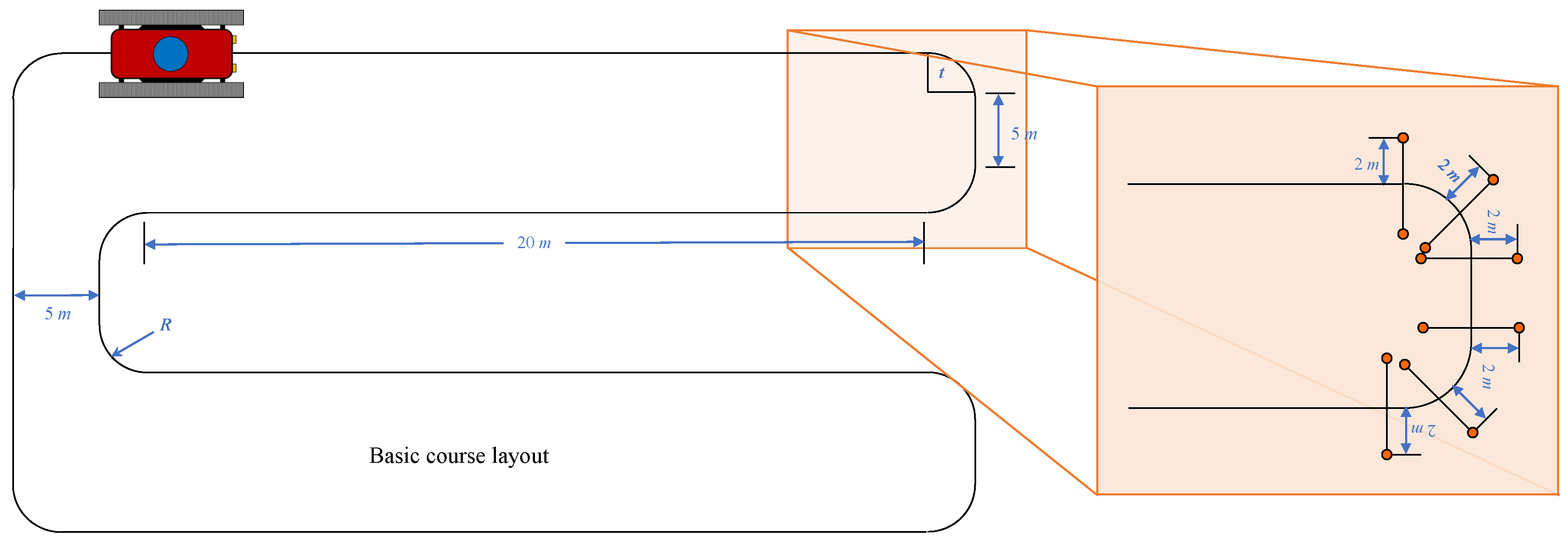
Figure 12.
Behavior Test Course 2 layout with details of the flag/marker placements. The distance values given should be taken only as examples and should be adjusted according to the requirements and testing plan for the vehicle undergoing evaluation.
Figure 12.
Behavior Test Course 2 layout with details of the flag/marker placements. The distance values given should be taken only as examples and should be adjusted according to the requirements and testing plan for the vehicle undergoing evaluation.
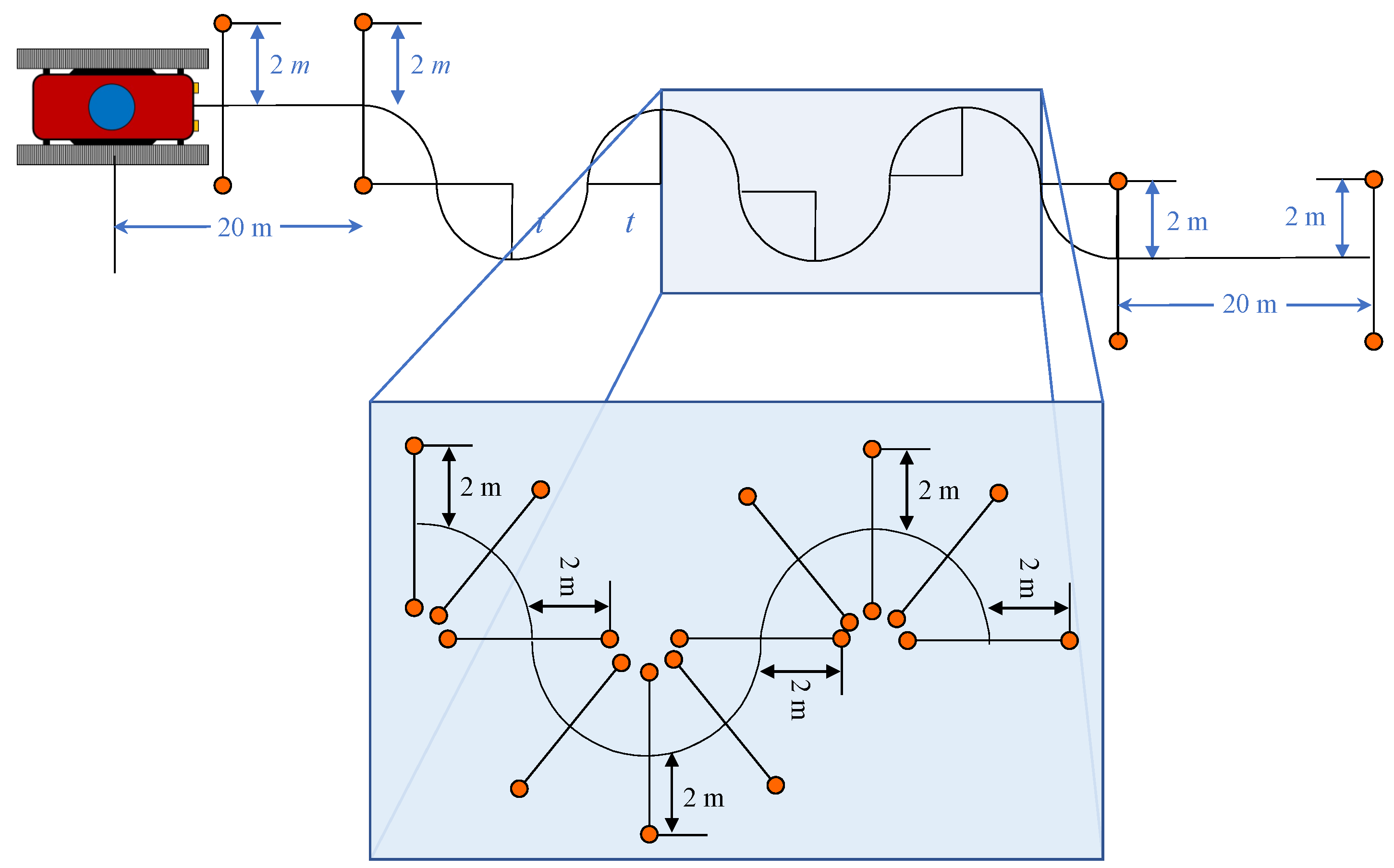
Figure 13.
Behavior Test Course 3 layout with details of the flag/marker placements. The distance values given should be taken only as examples and should be adjusted according to the requirements and testing plan for the vehicle undergoing evaluation.
Figure 13.
Behavior Test Course 3 layout with details of the flag/marker placements. The distance values given should be taken only as examples and should be adjusted according to the requirements and testing plan for the vehicle undergoing evaluation.
Figure 14.
Behavior Test Course 4 layout with details of the flag/marker placements. The distance values given should be taken only as examples and should be adjusted according to the requirements and testing plan for the vehicle undergoing evaluation.
Figure 14.
Behavior Test Course 4 layout with details of the flag/marker placements. The distance values given should be taken only as examples and should be adjusted according to the requirements and testing plan for the vehicle undergoing evaluation.
Figure 15.
Behavior Test Course 5 layout (assuming no obstacles are used).
Figure 15.
Behavior Test Course 5 layout (assuming no obstacles are used).
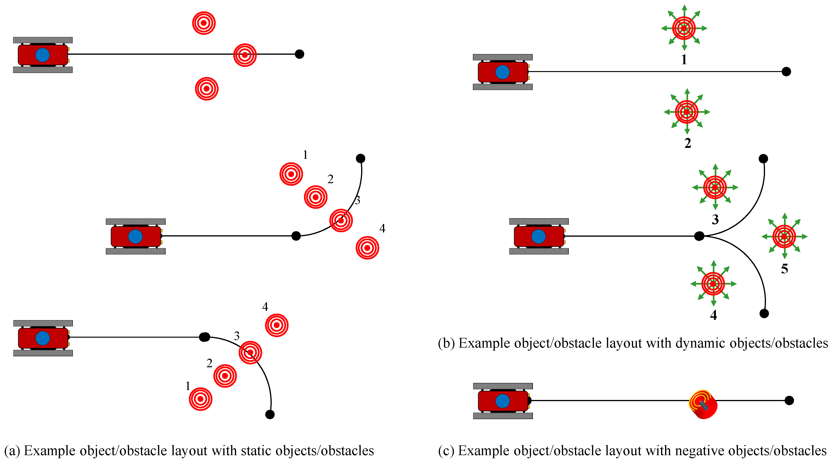
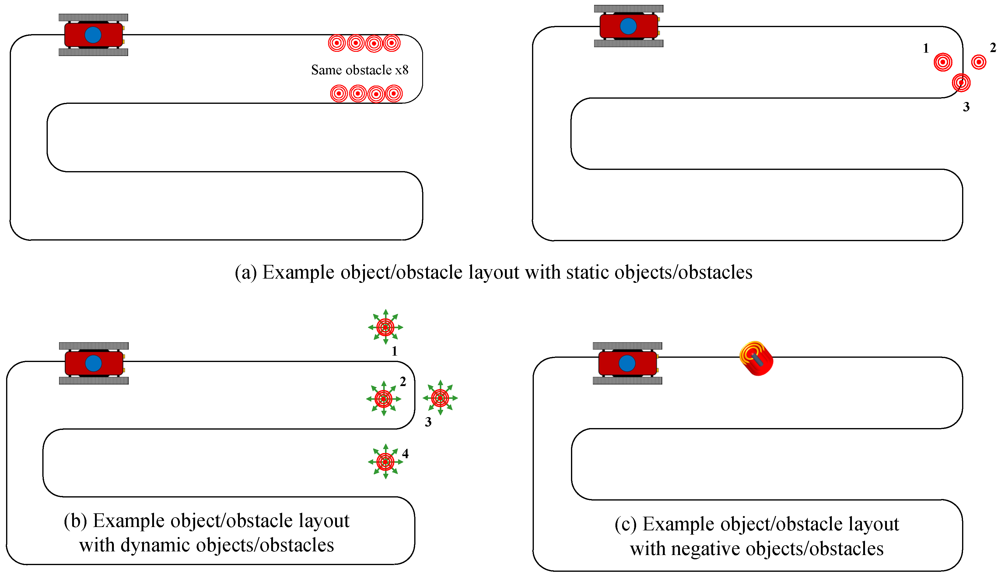
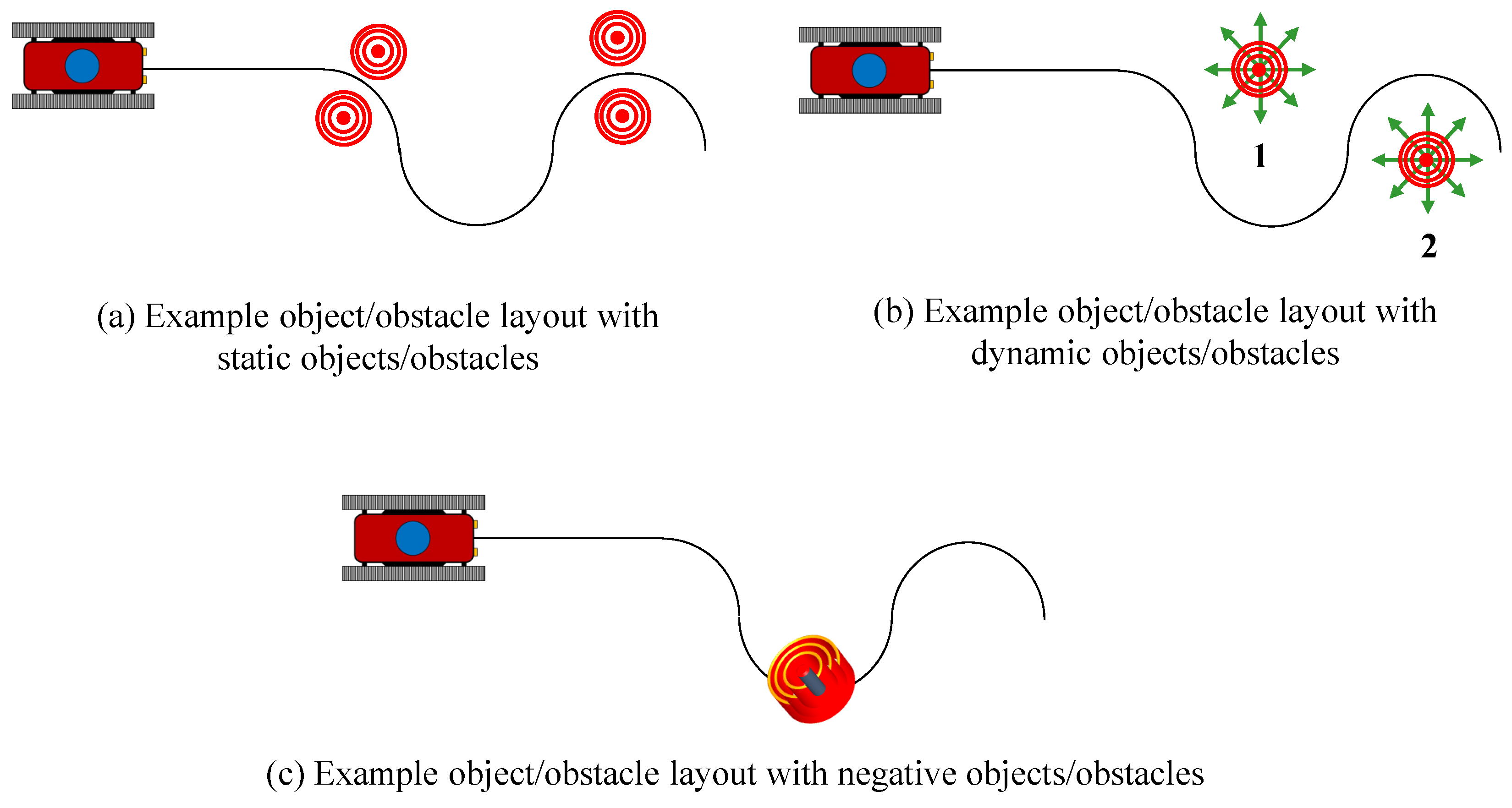
Figure 16.
Behavior Test Course 1 layouts with example objects/obstacles where the objects/obstacles are (a) static, (b) dynamic, and (c) negative. The objects/obstacles may be diverse or may be several of the same type; one or several may be used for the tests.
Figure 16.
Behavior Test Course 1 layouts with example objects/obstacles where the objects/obstacles are (a) static, (b) dynamic, and (c) negative. The objects/obstacles may be diverse or may be several of the same type; one or several may be used for the tests.
Figure 17.
Behavior Test Course 2 layouts with example objects/obstacles where the objects/obstacles are (a) static, (b) dynamic, and (c) negative. The objects/obstacles may be diverse or may be several of the same type; one or several may be used for the tests.
Figure 17.
Behavior Test Course 2 layouts with example objects/obstacles where the objects/obstacles are (a) static, (b) dynamic, and (c) negative. The objects/obstacles may be diverse or may be several of the same type; one or several may be used for the tests.
Figure 18.
Behavior Test Course 3 layouts with example objects/obstacles where the objects/obstacles are (a) static, (b) dynamic, and (c) negative. The objects/obstacles may be diverse or may be several of the same type; one or several may be used for the tests.
Figure 18.
Behavior Test Course 3 layouts with example objects/obstacles where the objects/obstacles are (a) static, (b) dynamic, and (c) negative. The objects/obstacles may be diverse or may be several of the same type; one or several may be used for the tests.
Figure 19.
Behavior Test Course 4 layouts with example objects/obstacles where the objects/obstacles are (a) static, (b) dynamic, and (c) negative. The objects/obstacles may be diverse or may be several of the same type; one or several may be used for the tests.
Figure 19.
Behavior Test Course 4 layouts with example objects/obstacles where the objects/obstacles are (a) static, (b) dynamic, and (c) negative. The objects/obstacles may be diverse or may be several of the same type; one or several may be used for the tests.
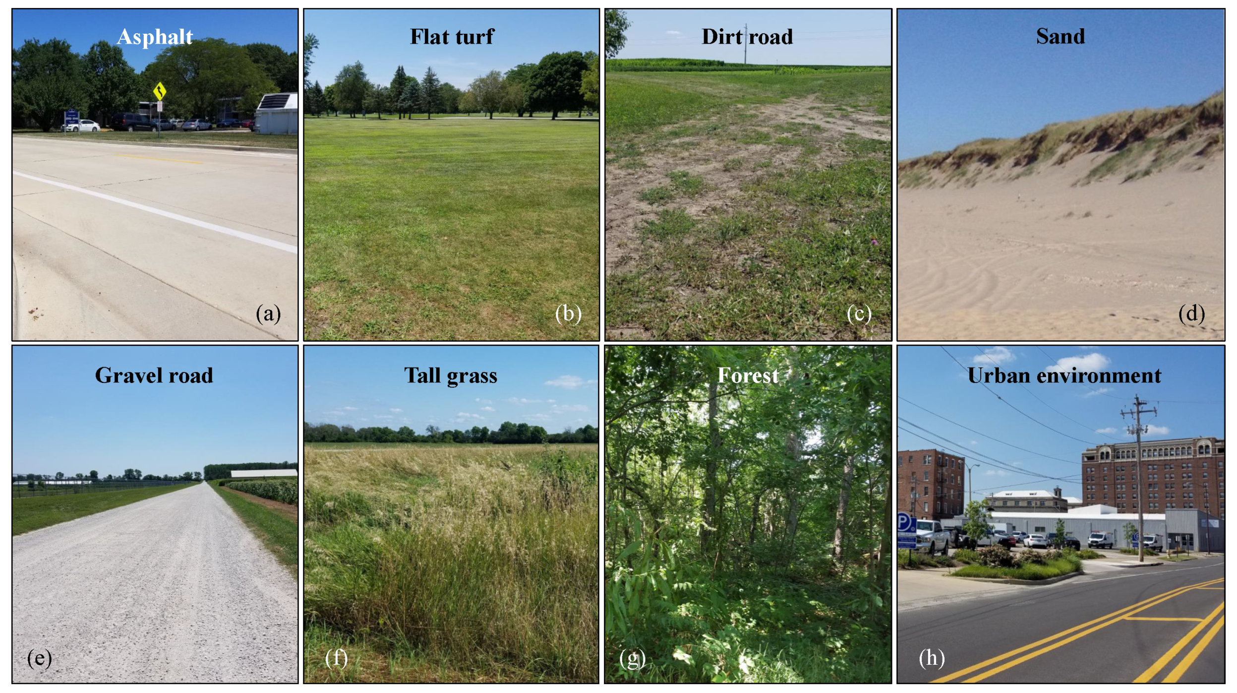
Figure 20.
Example terrain complexity for (
a) paved asphalt, (
b) flat turf, (
c) dry dirt road, (
d) sand [
56], (
e) gravel road, (
f) tall grass, (
g) forest, and (
h) an urban environment.
Figure 20.
Example terrain complexity for (
a) paved asphalt, (
b) flat turf, (
c) dry dirt road, (
d) sand [
56], (
e) gravel road, (
f) tall grass, (
g) forest, and (
h) an urban environment.
Table 1.
Example behavior testing requirements table for manual operation (MO), semi-autonomous and tele-operation (SA/TO), and autonomous operation (AO). Requirements are system-dependent and the designation of requirements and goals should be developed by the system stakeholders on a project-by-project basis. Blank cells indicate requirements not relevant or not included in the function or testing of the system under development.
| Example System Behavior for Evaluation | Control Mode |
|---|
| | MO | SA/TO | AO |
|---|
| Basic navigation | Required | Required | Goal |
| Route planning | - | Goal | Goal |
| Status communication | Required | Required | Required |
| Observe and report near-vehicle status | - | Goal | Required |
| Detect and evaluate the state of terrain features | - | - | Required |
| Detect and report nearby human activity | Goal | - | Goal |
| Search area | - | Required | Goal |
| Avoid areas | Required | Required | Required |
| Avoid and negotiate static and dynamic obstacles | - | Goal | Required |
Table 2.
Example behavior modes and functions in a field robotic system.
Table 2.
Example behavior modes and functions in a field robotic system.
| Level | Modes and Functions | Level | Modes and Functions |
|---|
| Vehicle design | Safety | Robotics | Safety |
| | Stability | | Sensors |
| | Braking | | Software |
| | Turning radius | | Communication |
| | Actuation | | Tele-operation |
| | Boom operation | | Localization |
| | Ground clearance | | Navigation |
| | | | Terrain tracking |
| | | | Mission accomplishment |
| | | | Obstacle detection |
| | | | Obstacle avoidance |
Table 3.
Example obstacle log table examining the GPS coordinates, nature (natural or artificial, where artificial obstacles were placed by the evaluators as part of the test course), the mode (static or dynamic), navigational interference (interfering/no-interfering), and whether the obstacle or its effect was expected or unexpected (E/UE) before the tests began.
| Obstacle | GPS Coord | Nature | Mode | Nav Interference | E/UE |
|---|
| 1 | Large tree | XX.X, YY.Y | Natural | Static | Interference | Expected |
| 2 | Large rock (near ground) | XX.X, YY.Y | Natural | Static | Non-interference | Expected |
| 3 | Basketball | XX.X, YY.Y | Artificial | Static | Non-interference | Expected |
| 4 | Large farm animal | XX.X, YY.Y | Natural | Dynamic | Non-interference | Unexpected |
| 5 | Area of tall grass | XX.X, YY.Y | Natural | Static | Non-interference | Unexpected |
| 6 | Adversarial robot | XX.X, YY.Y | Artificial | Dynamic | Non-interference | Unexpected |
| 7 | Car (parked) | XX.X, YY.Y | Artificial | Static | Interference | Expected |
| 8 | Car (driving normally) | XX.X, YY.Y | Artificial | Dynamic | Interference | Expected |
| 9 | Small pond | XX.X, YY.Y | Natural | Static | Non-interference | Expected |
| 10 | Large building | XX.X, YY.Y | Natural | Static | Interference | Expected |
Table 4.
Major top-level functions and example important system parameters to be evaluated or adjusted during testing.
Table 4.
Major top-level functions and example important system parameters to be evaluated or adjusted during testing.
| Function | Example Qualitative Parameter |
|---|
| Safety | 1. Stopping distance relative to obstacle detection range, braking symmetry, and operation mode |
| | 2. Control stop and remote kill switch delay |
| | 3. Mode of operation of the vehicle once remotely stopped |
| | 4. Maximum acceleration and deceleration profiles |
| | 5. Range of obstacle detection and location of blind spots |
| Communication | 1. Effect of distance and communication loss from the user interface on the system behaviors under manual, SA/TO, and autonomous navigation |
| | 2. Bandwidth limitations throughout the range of operation |
| | 3. Effects of varying complex terrain (foliage, etc.) and weather |
| | 4. Line of sight requirements and communication range |
| Manual control | 1. Operator controllability |
| | 2. Time lag of signal (phase lag) from the operator to the vehicle |
| | 3. Communication range and effect radio transition |
| | 4. Operator use and control of vehicle stability issues at high speed, including roll-over prevention |
| | 5. Handling quality of the vehicle under manual control |
| | 6. Accuracy of the vehicle position and path under manual control |
| | 7. Time to accomplish mission |
| | 8. Steering system symmetry and controllability |
| | 9. The effect of vehicle speed on handling |
| | 10. Obstacle detection and behavior arbitration |
| | 11. Time to accomplish the mission compared to scenario with no obstacles |
| | 12. Actuator Fatigue—number of actuations required to accomplish the mission |
| | 13. The frequency and amplitude of steering actuation signals |
| | 14. Brake—when on or off, time and side engaged |
| | 15. Speed—frequency, direction and amplitude of velocity actuation signals |
| SA/TO | 1. Operator controllability in cooperation with the vehicle system |
| | 2. Time lag of signal from the operator to the vehicle and the control system |
| | 3. Communication range and effect radio transition |
| | 4. Operator/controller handling of vehicle stability issues at high speed, including roll-over prevention |
| | 5. Handling quality of the vehicle under SA/TO |
| | 6. Accuracy of the vehicle position and path under SA/TO |
| | 7. Time to accomplish mission |
| | 8. Steering system symmetry and controllability |
| | 9. The effect of vehicle speed on handling and control |
| | 10. Obstacle detection and negotiation |
| | 11. Time to accomplish the mission compared to scenario with no obstacles |
| | 12. Actuator Fatigue—number of actuations required to accomplish the mission |
| | 13. The frequency and amplitude of steering actuation signals |
| | 14. Brake—when on or off, time and side engaged |
| | 15. Speed—frequency, direction and amplitude of velocity actuation signals |
| Autonomous navigation | 1. Controllability—how well the operator or artificial intelligence can control the vehicle to accomplish the mission |
| | 2. Communication range and radio transition—the effects on autonomous navigation due to vehicle range at maximum range and when transitioning between radios, waypoints, or GPS-rich areas |
| | 3. Operator/controller handling of vehicle stability issues at high speed, including roll-over prevention |
| | 4. Handling—cornering ability of the vehicle under navigation controls |
| | 5. Accuracy—how well the vehicle follows a path under an autonomous mode |
| | 6. Time to accomplish mission |
| | 7. Effects of localization sensor loss—Effects of the loss of use of sensors used to aid in localization |
| | 8. Effects of discontinuities in path plan |
| | 9. Settling time and distance—the amount of time and distance it takes a vehicle to resume adequate path tracking once a landmark has been attained or path tracking segment completed |
| | 10. Distance error—How far the vehicle has departed from a path segment or line/arc connecting waypoints or other landmarks (physical or GPS coordinates) |
| | 11. Maximum distance error—absolute value of the maximum distance error the system experienced during the evaluation course |
| | 12. Heading error—How the direction of the vehicle has differed from the direction of a corresponding path segment or the line/arc between waypoints or other physical or digital landmarks |
| | 13. Maximum heading error—absolute value of the maximum heading error the system experienced during the evaluation course |
| | 14. Minimum path curvature—the minimum radius or change in direction of waypoint segments that the vehicle can adequately track |
| | 15. Overshoot/undershoot—the distance the vehicle goes beyond the next waypoint or path segment when transitioning through path segments or between other landmarks |
| | 16. Phase lead/lag—the degree the vehicle compensates or fails to compensate for future/current changes in segment or arc reference |
| | 17. Steering system symmetry |
| | 18. Obstacle detection and behavior arbitration—the effects on system behavior due to the presence of obstacles around the platform or when other behaviors are in conflict |
| | 19. Time—time to accomplish the mission compared to scenario with no obstacles |
| | 20. Actuator fatigue—number of actuation to accomplish the mission |
| | 21. Steering—frequency and amplitude of steering actuation signals |
| | 22. Brake—frequency and amplitude of brake actuation signals |
| | 23. Throttle—frequency and amplitude of throttle actuation signals |
Table 5.
Safety Evaluation 1 setup table.
Table 5.
Safety Evaluation 1 setup table.
| Test: Safety Evaluation 1 |
|---|
| Purpose | The purpose of this evaluation is to determine the braking response of the vehicle to an immediate stop command (i.e., activation of the remote kill switch). The response characteristics should be evaluated from the stopping distance and deceleration profile based on obstacle detection range, braking symmetry and the mode of operation of the vehicle once stopped. Additionally, the maximum acceleration and deceleration profile can be obtained. The course will be focus on SA/TO and autonomous modes; manual operation is not necessary to test, as a remote kill switch is not necessary when the operator is in complete control of the system during operation. |
| Requirements | The vehicle shall effectively stop at design speed within a specified distance (e.g., 2 m), as well as within a specified distance (e.g., 3 m) at the maximum safe speed of the vehicle |
| | 2. The intelligent (autonomous) vehicle shall be in a stable mode once at a complete e-stop is engaged (i.e., 100% brake actuation). The stable stopped vehicle in an automated mode should have the brake engaged. |
| Variables | 1. GPS coordinates of obstacle and vehicle |
| | 2. Vehicle heading |
| | 3. Vehicle speed |
| Specifications | 1. Vehicle will be accelerated to design speed and then at maximum rated speed for each mode of operation |
| | 2. The course will be run in the following sequence: tele-operation and navigation |
| | 3. The course should be laid out as demonstrated in Figure 8; the distanced for each phase of the evaluation are adjustable based on the design of the system under evaluation |
| | 4. Markers shall be used to mark the course and the point where the brakes are applied via E-stop and control stop |
| | 5. The course is predicted to take approximately 10 min to setup and 10 min to perform one evaluation |
Table 6.
Safety Evaluation 2 setup table.
Table 6.
Safety Evaluation 2 setup table.
| Test: Safety Evaluation 2 |
|---|
| Purpose | The purpose of this course is to evaluate the range of detection for an autonomous vehicle and directions from which signals may not be detected. It is assumed that this test will not be needed for manual (and most SA/TO) modes, as the system will be in continuous communication with the operator and its location will always be known in real time. |
| Requirements | The intelligent vehicle shall be capable of being detected by an observer at a minimum radius established by the stakeholders; this distance will depend on the terrain complexity and expected weather conditions. Warning signals shall be both audio and visual. |
| Variables | Distance from the vehicle where warning signals are detectable (visual, audio) |
| Specifications | 1. Vehicle will be stationary |
| | 2. The measurements should be taken from the front, sides and rear of the vehicle |
| | 3. Predicted time for one test will be 5 min to set up and 10 min to run the test |
Table 7.
Safety Evaluation 3 setup table.
Table 7.
Safety Evaluation 3 setup table.
| Test: Safety Evaluation 3 |
|---|
| Purpose | The purpose of this course is to evaluate obstacle detection for an autonomous vehicle including areas where objects may not be detected |
| Requirements | The intelligent vehicle shall be capable of detecting objects/obstacles around the system of a set minimum size and height above the ground via instruments (camera, LIDAR, etc.) at a specified minimum distance from the vehicle |
| Variables | Distance and direction from the vehicle where obstacles are detected |
| Specifications | 1. Vehicle will be stationary |
| | 2. The measurements should be taken from the front, sides and rear of the vehicle (in terms of as demonstrated in Figure 9) |
| | 3. A test will be required for each of the detection methods used; Figure 9b shows example expected patterns for a camera and LIDAR. The exact patterns will vary depending on the instruments and vehicle design, but great care should be taken to ensure their range and reliability meet or exceed the requirements for the system. |
| | 3. Setup time is expected to be 5 min and one evaluation is expected to require 2 h to complete |
Table 8.
Communications Evaluation setup table.
Table 8.
Communications Evaluation setup table.
| Test: Communications Evaluation |
|---|
| Purpose | The purpose of this course is to determine the limitations of the communication system between the user interface and the vehicle. The effect of variations of the vehicle in terms of distance and transitions between communication systems will be explored, as well as the effects on performance based on vehicle positioning close to the maximum range. With the introduction of terrain complexity, the effective communication range and line of sight requirements can also be affected and will be examined. The evaluations will be conducted in manual mode, SA/TO, and autonomous navigation modes. |
| Requirements | 1. The vehicle shall be capable of effectively operating behaviors throughout the complete range of the communication with graceful degradation based on the loss of bandwidth |
| | 2. The vehicle shall exhibit appropriate functionality throughout the communication range |
| | 3. Traversing the communication transition region shall only effect the streaming video flow |
| | 4. The performance of the system in performing tele-operation and autonomous navigation should degrade gracefully as line of site/ maximum communication range is attained |
| | 5. In the event of reaching maximum range, the vehicle should stop |
| Variables | 1. GPS coordinate information – vehicle and user interface |
| | 2. Vehicle mode |
| | 3. Video rate |
| | 4. Bandwidth usage requirements for operation (video, communications, etc.) |
| | 5. Lag in operator control |
| Specifications | 1. Vehicle will be operated in manual, SA/TO, and autonomous navigation modes in separate evaluations |
| | 2. The course will be as driven by the operator on the user interface with the intent of reaching maximum communication range |
| | 3. Under the additions of terrain complexity, efforts should be initiated to determine line-of-sight limitations |
| | 4. Setup is expected to require 5 min and each evaluation is expected to require about 45 min |
Table 9.
Behavior Evaluation 1 setup table.
Table 9.
Behavior Evaluation 1 setup table.
| Test: Behavior Evaluation 1 |
|---|
| Purpose | The purpose of this course is to evaluate the manual mode, SA/TO, and autonomous navigation behaviors performing basic tasks, including driving a straight line and handling accuracy at a variety of turning radii. The response characteristics will be evaluated for trajectory following accuracy, the required steering control effort, controllability, time to accomplish the mission and level of actuation for the controllers. Additionally, the lag of the controller and handling characteristics will be analyzed. |
| Requirements | 1. The time lag between the operator control unit generated signal should be within the time specified in the requirements document |
| | 2. Vehicle trajectory drift shall be below the maximum specified distance |
| | 3. The vehicle will not enter an unstable mode of operation |
| Variables | 1. The stakeholder-determined basic performance requirements, as described in Table 4 |
| | 2. Timing of operator control input compared to timing of actuator (measure of communication delay) |
| | 3. Vehicle speed |
| | 4. Vehicle specification information |
| | 5. Vehicle turning radius |
| Specifications | 1. Vehicle will be traveling at design operating speed |
| | 2. Two operators will be required for this evaluation |
| | 3. In SA/TO and autonomous navigation modes, the vehicle will be monitored and controlled by a remote operator on the user interface and locally by the second operator |
| | 4. The course should be laid out as demonstrated in Figure 11 |
| | 5. The first run for all modes will be on a straight line |
| | 6. Radius changes for left and right turns of the course will initiate at the vehicle minimum turn radius. Subsequent test runs will occur starting at the vehicle minimum turn radius and varying the minimum test radius incrementally in both left and right directions until the desired radius is attained |
| | 7. Markers should be placed 2 m on either side of the path where changes in segments occur and in the middle of arcs for SA/TO evaluations. |
| | 8. Course setup is expected to require 30 min, with 10 min run time for each evaluation |
Table 10.
Behavior Evaluation 2 setup table.
Table 10.
Behavior Evaluation 2 setup table.
| Test: Behavior Evaluation 2 |
|---|
| Purpose | The purpose of this course is to evaluate the manual mode, tele-operation, and autonomous navigation behaviors to minimum level disturbances, drift, disturbance rejection, and stability evaluations under maximal perturbations, tracking accuracy, the effects of phase lag present in the controller, settling time and control system reliability. The response characteristics will be evaluated for trajectory following error, and the required steering control effort. |
| Requirements | 1. The intelligent vehicle shall effectively traverse the course at design speed as well as at the maximum safe speed of the vehicle available under autonomous mode. Effective traverse implies a trajectory following error of less than a maximum distance specified in the requirements document and a maximum specified orientation error. |
| | 2. The vehicle will have a settling distance less than the specified distance at design speed, as well as at the maximum safe speed of the vehicle available under autonomous mode |
| | 3. Autonomous vehicle trajectory drift shall be below the maximum distance specified in the requirements document |
| | 4. The vehicle will not enter an unstable mode of operation |
| Variables | 1. The stakeholder-determined basic performance requirements, as described in Table 4 |
| | 2. GPS coordinates of path and vehicle |
| | 3. Vehicle heading |
| | 4. Reference segments for controller response |
| | 5. All planned trajectory information in GPS coordinates |
| | 6. Actuator command signal from operator or high level control |
| | 7. Actuator position/angle feedback |
| | 8. Actuator lag |
| | 9. Vehicle speed |
| | 10. Vehicle specification information |
| | 11. Turning radius |
| Specifications | 1. Vehicle will be traveling at standard operating speed |
| | 2. Two operators will be required for this evaluation |
| | 3. In manual, SA/TO, and autonomous modes, the vehicle will be controlled and/or monitored by a remote operator through a user interface and locally by the vehicle supervisor |
| | 4. The course should be laid out as demonstrated in Figure 12 where t represents the vehicle-specific minimum turning radius |
| | 5. Markers should be placed 2 m on either side of the path where changes in segments occur to help guide navigation |
| | 6. Expected run time for each case will be 30 min, with one hour expected for setting up the course |
Table 11.
Behavior Evaluation 3 setup table.
Table 11.
Behavior Evaluation 3 setup table.
| Test: Behavior Evaluation 3 |
|---|
| Purpose | The purpose of this course is to evaluate the manual, SA/TO, and autonomous navigation behaviors response to maximum disturbances, determination of handling issues and the effects of phase lag present in the controller. The response characteristics will be evaluated the required steering control effort from the operator. |
| Requirements | 1. The intelligent vehicle shall effectively traverse the course at design speed as well as at the maximum safe speed of the vehicle available under autonomous mode. Effective traverse implies trajectory following and orientation errors of less than the maximum distance specified in the system requirements with minimal high frequency oscillation. |
| | 2. The vehicle will not enter an unstable mode of operation |
| Variables | 1. The stakeholder-determined basic performance requirements, as described in Table 4 |
| | 2. GPS coordinates of path and vehicle |
| | 3. Vehicle heading |
| | 4. Reference segments for controller response |
| | 5. All planned trajectory information in GPS coordinates |
| | 6. Actuator command signal from operator or high level control |
| | 7. Actuator position/ angle feedback |
| | 8. Timing of operator control input compared to timing of actuators |
| | 9. Vehicle specification information |
| | 10. Vehicle speed |
| | 11. Turning radius |
| Specifications | 1. Vehicle will be traveling at standard operating speed |
| | 2. Two people will be required for this evaluation |
| | 3. In tele-operation and autonomous navigation behaviors, the vehicle will be controlled by a remote operator on the User Interface |
| | 4. The course should be laid out as demonstrated in Figure 13 where t represents the vehicle-specific minimum turning radius |
| | 5. Markers should be placed 2 m on either side of the path where changes in segments occur to help guide tele-operation |
| | 6. Time investment for the test is anticipated to be one hour for the course setup and a half hour for each evaluation |
Table 12.
Behavior Evaluation 4 setup table.
Table 12.
Behavior Evaluation 4 setup table.
| Purpose | The purpose of this course is to evaluate the steering response to maximum level disturbances, disturbance rejection, stability evaluations under maximal perturbations, tracking accuracy and the effects of phase lag present in the controller. The response characteristics will be evaluated for trajectory following error, and the required steering control effort. Trajectory drift will be evaluated in terms of orientation, distance, and course shift through multiple passes. |
| Requirements | 1. The intelligent vehicle shall effectively traverse the course at design speed as well as at the maximum safe speed of the vehicle available under autonomous mode. Effective traverse implies a trajectory following and orientation error within the tolerance specified in the system requirements document with minimal high-frequency oscillation. |
| | 2. The vehicle will not enter an unstable mode of operation |
| Variables | 1. The stakeholder-determined basic performance requirements, as described in Table 4 |
| | 2. GPS coordinates of path and vehicle |
| | 3. Vehicle heading |
| | 4. Reference segments for controller response |
| | 5. All planned trajectory information in GPS coordinates |
| | 6. Actuator command signal from operator or high level control |
| | 7. Actuator position/ angle feedback |
| | 8. Timing of operator control input compared to timing of actuators |
| | 9. Vehicle speed |
| | 10. Vehicle specification information |
| | 11. Turning radius |
| Specifications | 1. Vehicle will be traveling at standard operating speed |
| | 2. This evaluation will require two operators, one to control the vehicle remotely and one to escort it in case of problems |
| | 3. In tele-operation and autonomous modes, the vehicle will be controlled by a remote operator on the user interface |
| | 4. The course should be laid out as demonstrated in Figure 14 where t represents the vehicle-specific minimum turning radius |
| | 5. Markers should be emplaced 2 m on either side of the path where changes in segments occur to help guide navigation |
| | 6. Course setup is expected to take 10 min per iteration, followed by a 20 min evaluation period |
Table 13.
Behavior Evaluation 5 setup table.
Table 13.
Behavior Evaluation 5 setup table.
| Test: Behavior Evaluation 5 |
|---|
| Purpose | The purpose of this course is to evaluate the steering controller response to varying disturbances in the form of varying trajectory curvature. The response characteristics will be evaluated for trajectory following error, and the required steering control effort. Trajectory drift will be evaluated in terms of orientation, distance and course shift through multiple passes. |
| Requirements | 1. The intelligent vehicle shall effectively traverse the course at design speed as well as at the maximum safe speed of the vehicle available under autonomous mode. Effective traverse implies a trajectory following error of less than a maximum distance of meters and a maximum orientation error of degrees under all conditions with minimal high frequency oscillation. |
| | 2. The vehicle will not enter an unstable mode of operation |
| Variables | 1. The stakeholder-determined basic performance requirements, as described in Table 4 |
| | 2. GPS coordinates of path and vehicle |
| | 3. Vehicle heading |
| | 4. Reference segments for controller response |
| | 5. All planned trajectory information in GPS coordinates |
| | 6. Actuator command signal from operator or high level control |
| | 7. Actuator position/ angle feedback |
| | 8. Timing of operator control input compared to timing of actuators |
| | 9. Vehicle speed |
| | 10. Vehicle specification information |
| | 11. Turning radius |
| Specifications | 1. Vehicle will be traveling at standard operating speed |
| | 2. Two people will be required for this evaluation |
| | 3. The vehicle will be controlled by a remote operator on the User Interface |
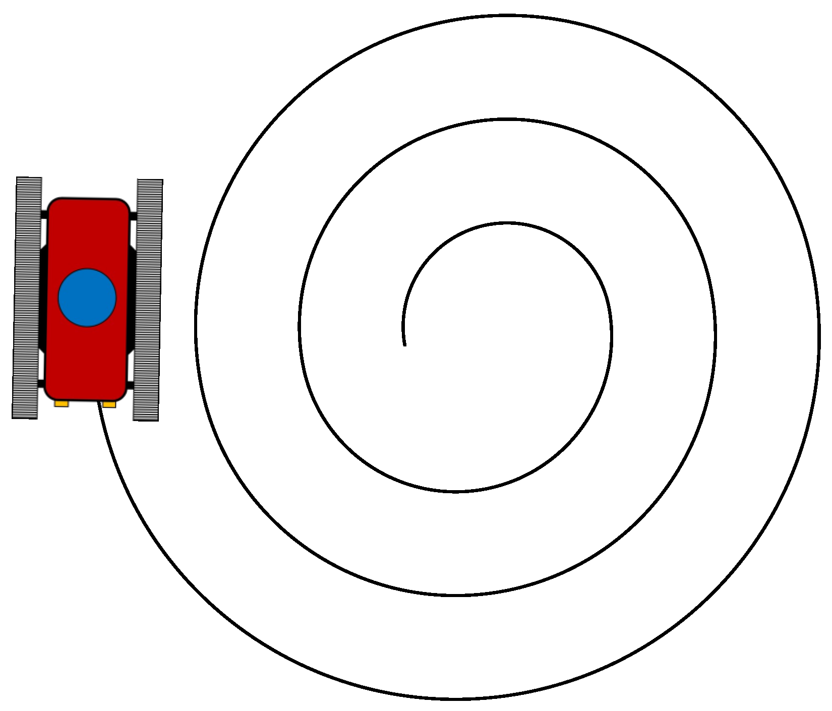
| | 4. The course should be laid out as demonstrated in the figure on the following page |
| | 5. Course setup time is expected to take 15 min per iteration and testing is expected to take an additional 15–20 min |
Table 14.
Example terrain parameters table for a gravel road environment.
Table 14.
Example terrain parameters table for a gravel road environment.
| Terrain: Gravel Road |
|---|
| Ground slope | |
| Gravel average size x | 20 mm |
| Standing water depth | 45 mm |
| Drive-over obstacle height | 50 mm |
| Snow depth | mm |
| Negative obstacle depth | 75 mm |
| Negative obstacle diameter y | 200 mm |
| Temperature T | 0 C 40 C |
| Relative humidity | |
| Mud depth | 10 mm |
| Sand depth | 8 mm |


