Article

Leaf Area Estimation of Reconstructed Maize Plants Using a Time-of-Flight Camera Based on Different Scan Directions

by
Manuel Vázquez-Arellano
1,*,
David Reiser
1,
Dimitrios S. Paraforos
1,
Miguel Garrido-Izard
2 and
Hans W. Griepentrog
1
1
Institute of Agricultural Engineering, University of Hohenheim, Garbenstrasse 9, 70599 Stuttgart, Germany
2
Laboratorio de Propiedades Físicas (LPF)-TAGALIA, Technical University of Madrid, 28040 Madrid, Spain
*
Author to whom correspondence should be addressed.
Robotics 2018, 7(4), 63; https://doi.org/10.3390/robotics7040063
Submission received: 19 September 2018 / Revised: 8 October 2018 / Accepted: 11 October 2018 / Published: 11 October 2018
(This article belongs to the Special Issue Agricultural and Field Robotics)

Abstract

:
The leaf area is an important plant parameter for plant status and crop yield. In this paper, a low-cost time-of-flight camera, the Kinect v2, was mounted on a robotic platform to acquire 3-D data of maize plants in a greenhouse. The robotic platform drove through the maize rows and acquired 3-D images that were later registered and stitched. Three different maize row reconstruction approaches were compared: reconstruct a crop row by merging point clouds generated from both sides of the row in both directions, merging point clouds scanned just from one side, and merging point clouds scanned from opposite directions of the row. The resulted point cloud was subsampled and rasterized, the normals were computed and re-oriented with a Fast Marching algorithm. The Poisson surface reconstruction was applied to the point cloud, and new vertices and faces generated by the algorithm were removed. The results showed that the approach of aligning and merging four point clouds per row and two point clouds scanned from the same side generated very similar average mean absolute percentage error of 8.8% and 7.8%, respectively. The worst error resulted from the two point clouds scanned from both sides in opposite directions with 32.3%.

1. Introduction

Information such as stem diameter, plant height, leaf angle, leaf area (LA), number of leaves, and biomass are of particular interest for agricultural applications such as precision farming, agricultural robotics, and automatic phenotyping for plant breeding purposes. A very important plant parameter is the LA because it provides important information about the plant status and is closely related to the crop yield [1] and its quality [2]. However, LA is one of the most difficult parameters to measure [3] since manual methods are time-consuming and the 2-D image-based ones are not very accurate because of leaf occlusion and color variation due to sunlight [4]. A commonly used index describing the LA is the leaf area index (LAI), which is the total one-sided area of leaf tissue per unit ground surface area [5].
In general, 3-D imaging could be a good method for a fast and more accurate LA measurement, compared to the 2-D approach, since it does not depend on the position of the leaves (of the plant) in space relative to the image acquisition system [6]. However, 3-D scanning systems are normally very expensive for sensing or monitoring applications. Therefore, economically affordable 3-D sensors are a key factor for the successful implementation of 3-D imaging systems in agriculture. A low-cost time-of-flight (TOF) camera, like the Kinect v2 (Microsoft, Redmond, WA, USA), has proven to have sufficient technical capabilities for 3-D plant reconstruction [7], stem position, and height determination [8] for agricultural applications that require precise sensing such as precision agriculture and agricultural robotics, among others.
Previous research has been done using the Kinect v2 for weed volume estimation [9] in the open field on a sunny day (40,000 lux), without mentioning sensing problems, as well as high-throughput phenotyping of cotton in open field [10]. The former did not rely on a shadowing device, whereas the latter did; it could therefore be also expected to work under outdoor conditions. Hämmerle and Höfle [11] measured the maize crop height in open field under real conditions including wind and sunlight, and the measurements were slightly below the results presented in other studies due to the challenging field conditions and the complex architecture of the maize plant at late stage. Hue et al. [12] measured the LA and the projected LA, among other parameters, of 63 pots of lettuce by subsampling the generated point cloud and using a triangular mesh to reconstruct the surface. The LA measurement was calculated by adding the area of all triangles in the mesh, and the projected LA was the area projected onto the xy plane along the z-axis. The total LA measurement had an R2 determination coefficient of 0.94 and the projected LA, 0.94. However, while the projected LA followed a linear distribution, the total LA measurements followed a power-law distribution due to occlusion when the plant had more leaves.
Paulus et al. [13] measured the LA of sugar beet leaves, relying on the structured light-based Kinect v1. They mentioned the importance of acquiring 3-D data of above-ground plant organs, such as plant leaves and stems, in order to extract 3-D plant parameters. The R2 determination coefficients were 0.43 and 0.93 for LA and projected LA measurement, respectively. They explained that the high error in the LA estimation was due to strong smoothing effects that produced overestimated measurements. However, the projected LA measurements, defined as ground cover, reduced those effects. They stated that the projected LA can be used as a proxy for agricultural productivity because the photosynthetic activity was linked to the LA directed to sunlight. Nakarmi and Tang [14] developed an automatic inter-plant spacing sensing system for early stage maize plants. They placed the TOF camera in a side-view position since the purpose was to measure the distance between maize stems, and that camera position was optimal. In [15], a TOF camera was also used to extract the stem diameter, leaf length, leaf area, and leaf angle of individual maize plants, whereas in [16], a TOF camera was mounted on a robotic arm to explore its possibilities for chlorophyll measurements. Another publication by Colaço et al. [17] focused on canopy reconstruction, using a light detection and ranging sensor, for high-throughput phenotyping.
The aim of this research was to estimate the LA of maize plants by merging point clouds obtained from different 3-D perspective views. Three approaches were evaluated by three different methodologies: (a) aligning and merging point clouds from two paths and two directions; (b) aligning point clouds scanned from the same side of the crop row; and (c) aligning point clouds scanned from opposite directions and different paths. In order to estimate the LA, a methodology was proposed for reconstructing the surface of a rasterized point cloud after the alignment and merge. The main contribution of this research was to reconstruct the surface and to estimate the LA of entire maize crop rows. Previous research papers focused only on reconstructing the LA of single plants. Therefore, this research sets a new milestone for high-throughput LA estimation.

2. Materials and Methods

2.1. Hardware and Sensors

A TOF camera mounted on a robotic platform, the technical details of which are described by Reiser et al. [18], was used to acquire 3-D data of maize plants in a greenhouse as shown in Figure 1. The TOF camera was mounted at the front of the robotic platform at a height of 0.94 m with a downward angle of 45 degrees. The SPS930 robotic total station (Trimble Navigation Limited, Sunnyvale, CA, USA) tracked the position of the robot, with sub-centimeter accuracy [19], by aiming at the MT900 Target Prism. In order to measure the orientation of the robot while driving, an Inertial Measurement Unit (IMU) (VectorNAV, Dallas, TX, USA) VN-100 was used.

2.2. Experimental Setup

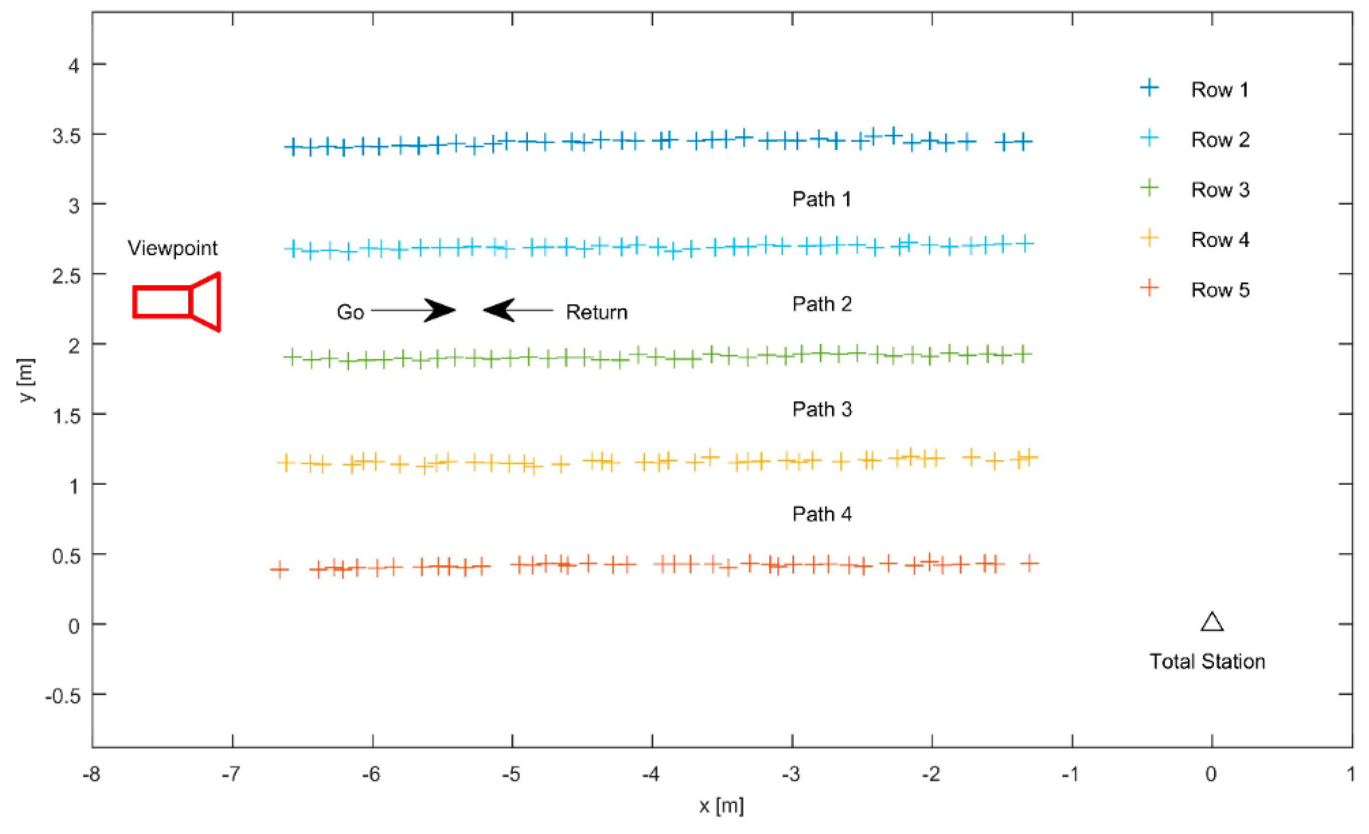
The 3-D data acquisition was done in a greenhouse at the University of Hohenheim (see Figure 1). The seeding was performed in five rows (see Figure 2); the row spacing (inter-row) was 0.75 m and the plant spacing (intra-row) was 0.13 m. Every row had 41 plants with a length of 5.2 m, and the plant growth stage was between V1 and V4. The LA was measured by hand using a measurement tape. The robotic platform was driven, using a joystick, at a maximum driving speed of 0.8 m·s−1 through every path in the go and return direction to obtain 2.5-D images that were later transformed to 3-D images. At every headland, the robot was turning 180 degrees; therefore, the 3-D perspective view was different in the go and return directions of every path. A viewpoint was established (camera plot in Figure 2), to avoid confusion between the left and right side of the crop row. Every single plant was manually measured and parameters such as plant height, number of leaves, stem diameter, and LA were registered. The hardware and sensors used during the experiment are explained in detail by Vázquez-Arellano et al. [7].

2.3. Data Processing

The raw data of this research consisted of the maize point clouds generated by using the registration and stitching process methodology developed by Vázquez-Arellano et al. [7]. The point clouds were processed using the Computer Vision System Toolbox of MATLAB R2016b (MathWorks, Natick, MA, USA). Additionally, CloudCompare [20] was used for point cloud rasterization and surface reconstruction and for assembling the individual 3-D images, using the Iterative Closes Point (ICP) [21], which constituted the generated maize crop rows. In this research, three different maize row point cloud alignments were done to investigate the trade-off of merging all four point clouds (Path 1 go, Path 1 return, Path 2 go, and Path 2 return), two point clouds from the same side of the crop row, such as Row 2 from the left side (i.e., Path 1 go and Path 1 return), and from both sides scanned from opposite directions (i.e., Path 1 go and Path 2 return).

2.4. Leaf Area Estimation

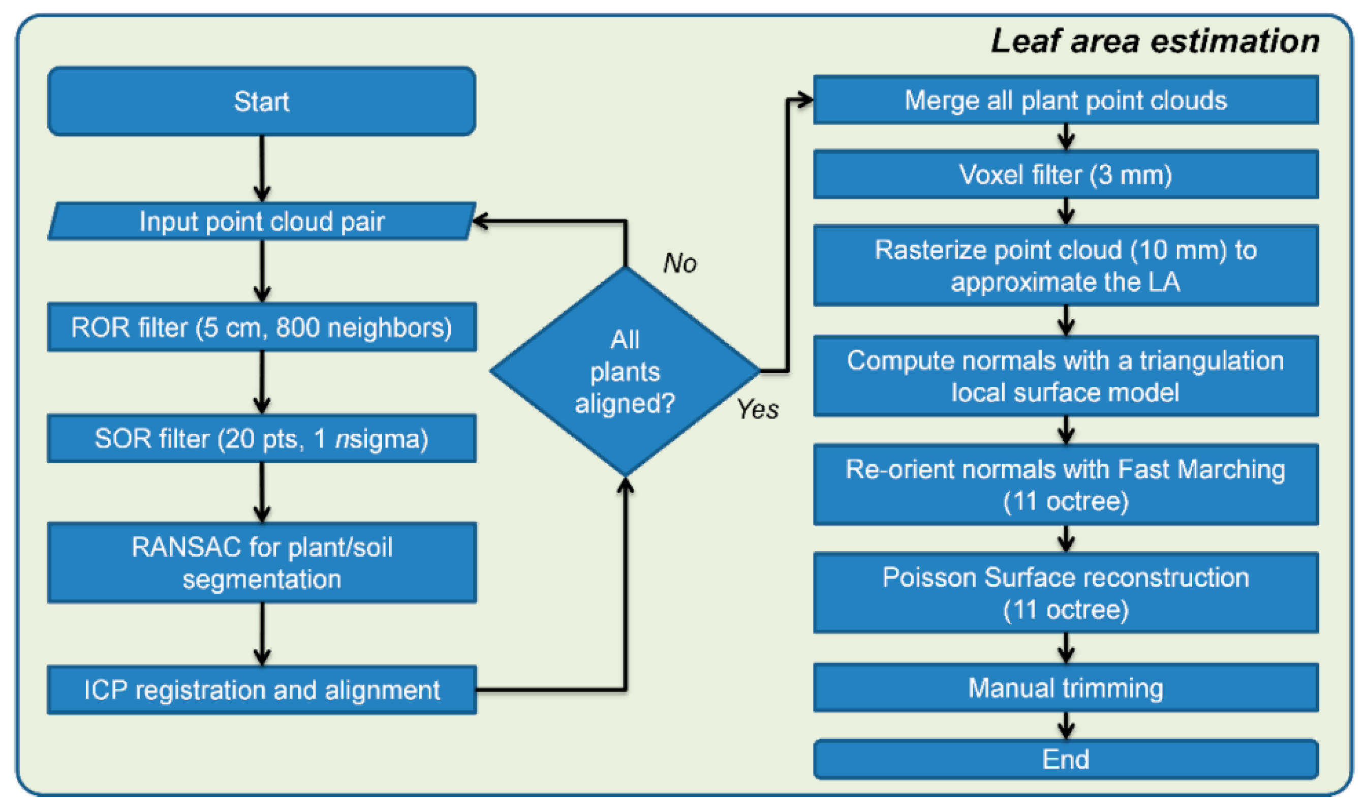
The methodology for LA estimation in this investigation (depicted in Figure 3) was based on the generated maize row point clouds generated in a previous research, as previously mentioned. These point clouds were initially imported pairwise, and each of the point clouds was filtered using a radius outlier removal (ROR) filter and a statistical outlier removal (SOR) filter. The ROR filter was set to a radius of 5 cm with a minimum number of required neighbors of 800. The SOR filter was set to 20 points for the mean distance estimation with a standard deviation multiplier threshold nsigma equal to 1. Then, the Random Sample Consensus (RANSAC) algorithm [22] was applied for each point cloud pair with the maximum distance from an inlier to the plane set to half the theoretical intra-row distance between plants of 17 cm, resulting in 6.5 cm.
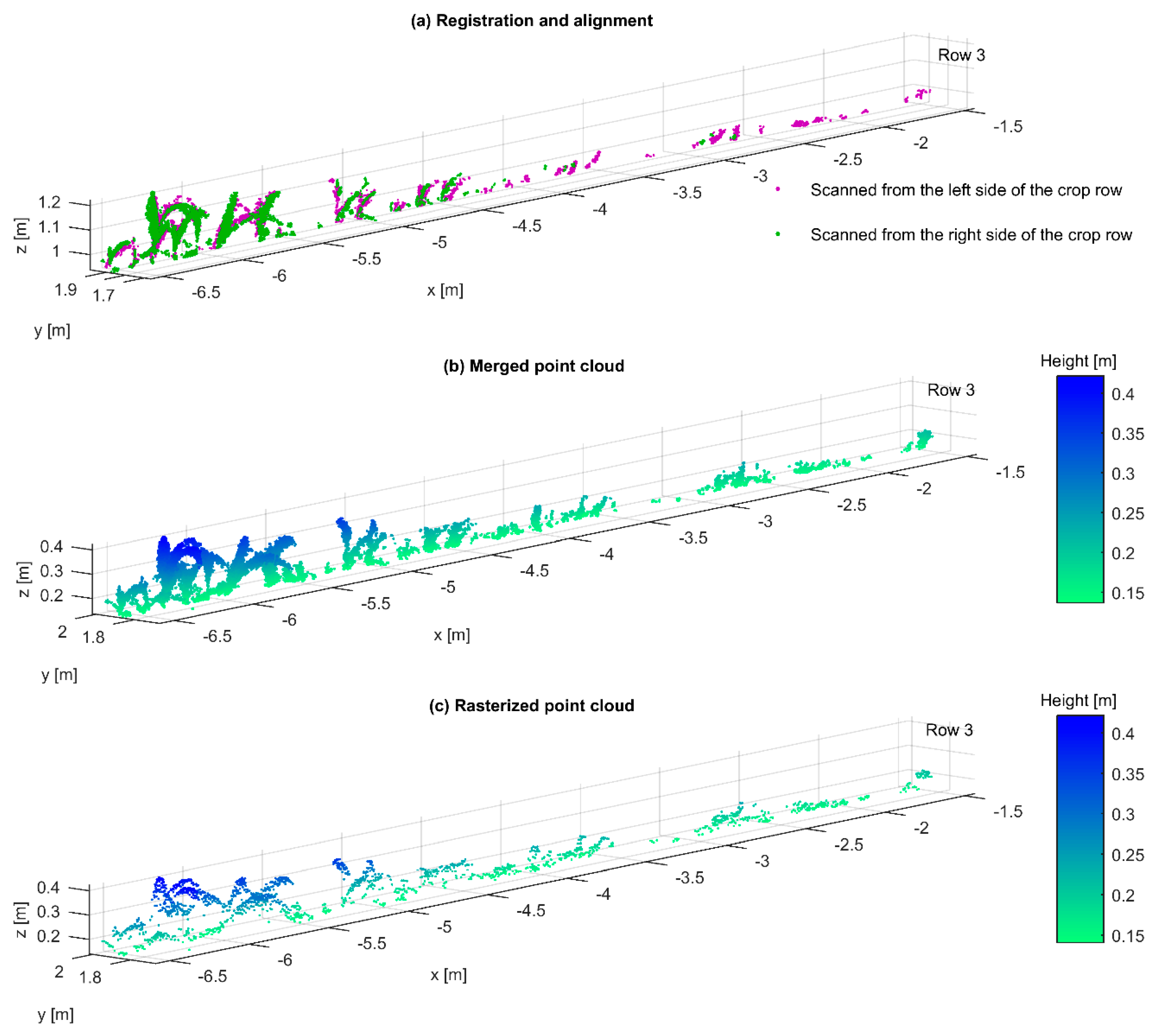
The point cloud pair was registered and aligned using the ICP (see Figure 4a). This process was performed one time for two point cloud alignment and three times for four point cloud alignment. After all the point clouds of every dataset were aligned, the next step was to merge them together. The merging process could produce duplicate points; therefore, a subsampling was applied using a voxel grid (3 mm × 3 mm × 3 mm) filter (see Figure 4b) to reduce the high point cloud density and remove duplicate points without losing important plant information. The next step was to rasterize the point cloud, following the same previously mentioned hypothesis, in order to obtain a point cloud generated with a projection in the z-axis with a grid step (cell) of 1 cm. Every point inside the cell was the one with the maximum height, in the case that more than one point was falling in each cell (see Figure 4c). After the rasterized point cloud was generated, the next step was to compute the normal. This computation was done using a triangulation local surface model for surface approximation with a preferred orientation in the z-axis.
Then, the normals were re-oriented in a fast and consistent way using the Fast Marching algorithm [23] with 11 octrees. A larger value would not be needed due to the sensing limitations of the TOF camera. This method attempts to re-orient all the normals of a cloud in a consistent way: starting from a random point, then propagating the normal orientation from one neighbor to the other. The main difficulty of this method is to find the right level of subdivision (cloud octree), because if the cells are too big, the propagation would be not accurate, and if they are too small, empty cells would appear and the propagation would not be possible in one sweep [20].
Finally, in order to estimate the LA, a mesh was generated by using the Poisson reconstruction method. The Poisson surface reconstruction is a global solution that considers all the data at once, and creates smooth surfaces that robustly approximate noisy data [24]. The octree depth was the main parameter to be set; the deeper the octree the finer the result, with the drawback of taking more processing time and memory. Although in this research an octree value of 11 was set for a more detailed reconstruction, a smaller value would not affect much the leaf area measurement. After a triangular mesh was generated with the Poisson surface reconstruction, the LA was calculated by simply adding the area of all the individual triangles.
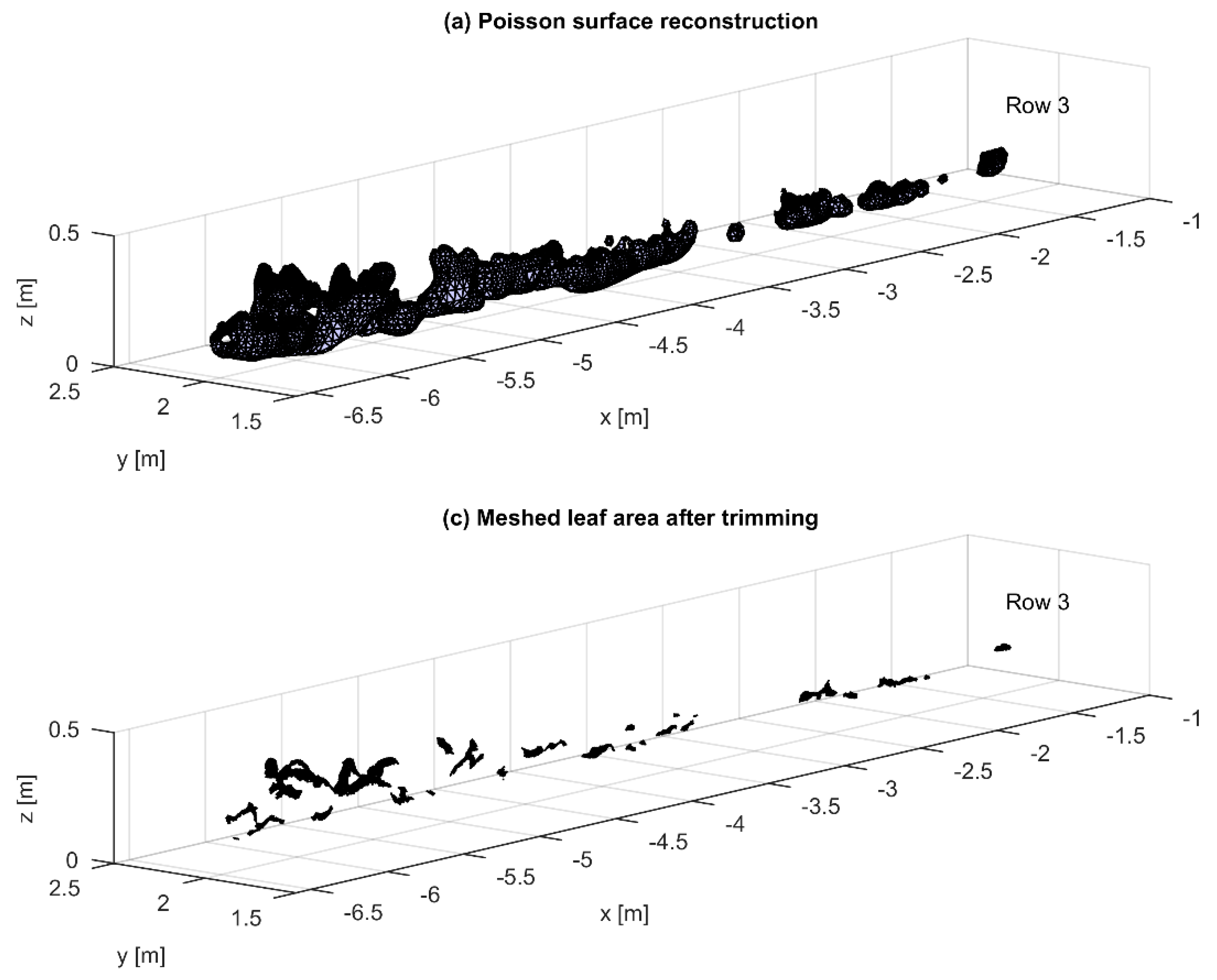
A characteristic of the Poisson reconstruction (see Figure 5a) is that it produces a watertight surface, which was not suitable for this study’s dataset where leaves were separated [25]. In order to trim the reconstructed surface to fit the point cloud (see Figure 5b), a surface trimming algorithm was applied [26]. This method pruned the surface according to the sampling density of the point cloud. The disadvantage of this algorithm was that, for non-watertight surfaces such as the leaves in this dataset, it was difficult to find the right parameters to trim the mesh. This problem was approached by identifying the biggest leaves in this point cloud and manually trimming them until the reconstructed surface fit the silhouette of the biggest leaves of the row point cloud. This parameter value was interactively found by removing the triangles with vertices having the lowest density values, which corresponded to the triangles that were the farthest from the input point cloud. If the trimming was done beyond the point cloud limits, the reconstructed surface started to shift the leaf border beyond the real one, thus producing overestimated values as reported by Paulus et al. [13]. In addition, the density value was reduced if a mesh membrane was generated between leaves with close spatial proximity, because this effect would generate an overestimated LA value.
The LA reference measurements were obtained by measuring the length and width of every leaf in the plants; if the leaf was touching the ground, it was not considered. In order to correct the LA measurements, a factor was used as in Montgomery [27]:
L A = 0.75 × L × W ,
where L and W are the length and width of the maize leaf, respectively. In order to evaluate the error in the estimated measurements, the root mean square error (RMSE) was calculated with the following formula:
RMSE =   m e a n ( t a ) 2 ,
where t represents the target measurement and a the actual measurement. Additionally, the mean absolute percentage error (MAPE) was also considered. The MAPE was calculated using the following formula:
MAPE =   m e a n ( | t a t 100 | ) .

3. Results and Discussion

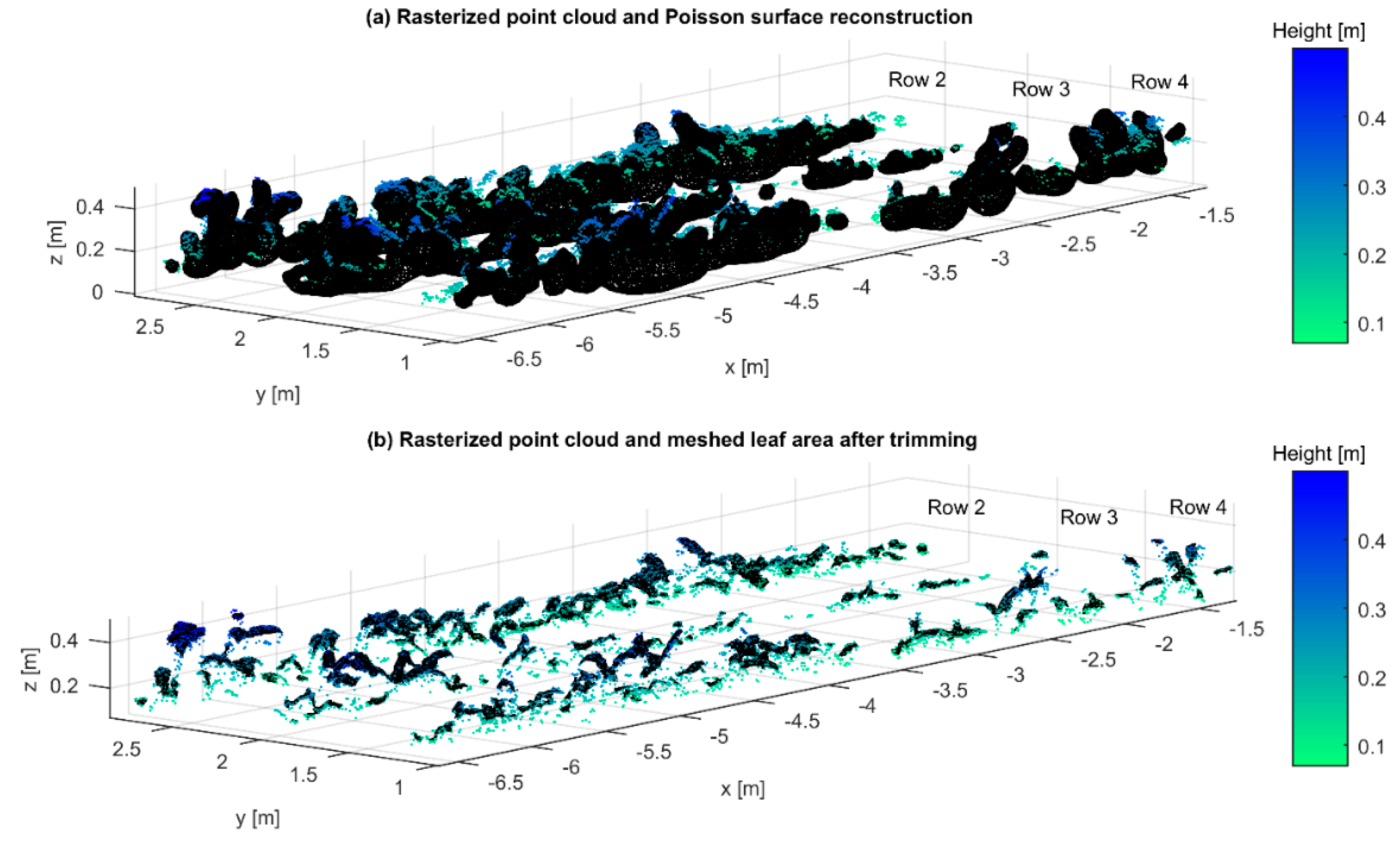
As previously mentioned, three different approaches were considered: (a) merging all four point clouds; (b) two point clouds scanned from the same side of the crop row; and (c) scanned from both sides in opposite directions. The result of the Poisson surface reconstruction generated from the rasterized point cloud projected in the z direction is shown in Figure 6a. Since the Poisson algorithm generated new meshes, it was required to trim them by adjusting the density value, which removed low-density meshes until they fit inside the boundaries of the point cloud that generated it first (see Figure 6b).
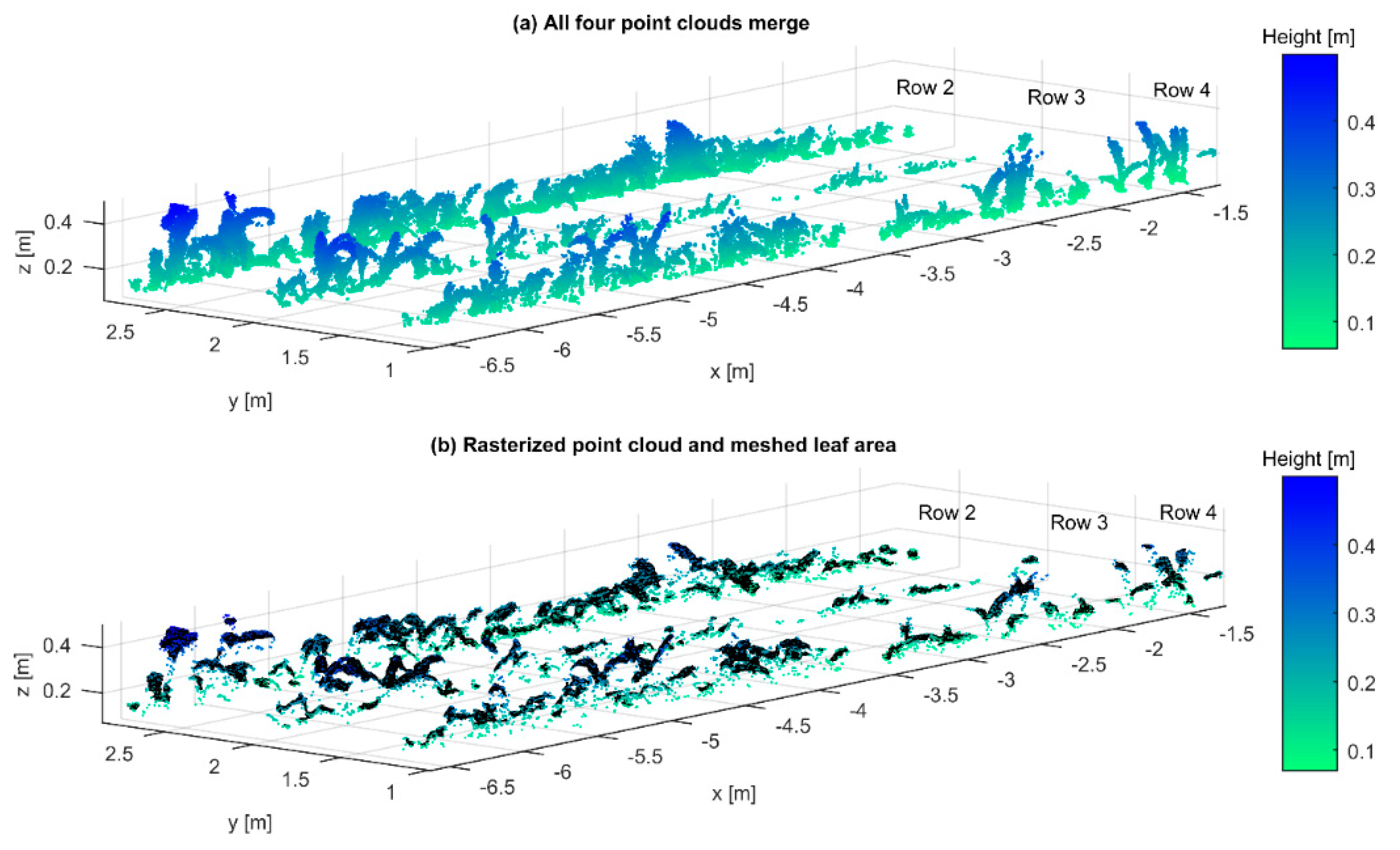
Table 1 shows that the RMSE and MAPE were 231 cm2 and 8.8%, respectively. This error was relatively small because the rasterized point clouds were well defined and they also had a relative continuity without duplicate points in the z-axis. In Figure 7a, the plants are thicker than they are in reality due to the error accumulated during the reconstruction of the maize row and the alignment and merging of the four point clouds. The rasterized point cloud and its meshed representation are shown in Figure 7b. With the mesh, it is possible to add the area of the all the triangles to know the total LA.
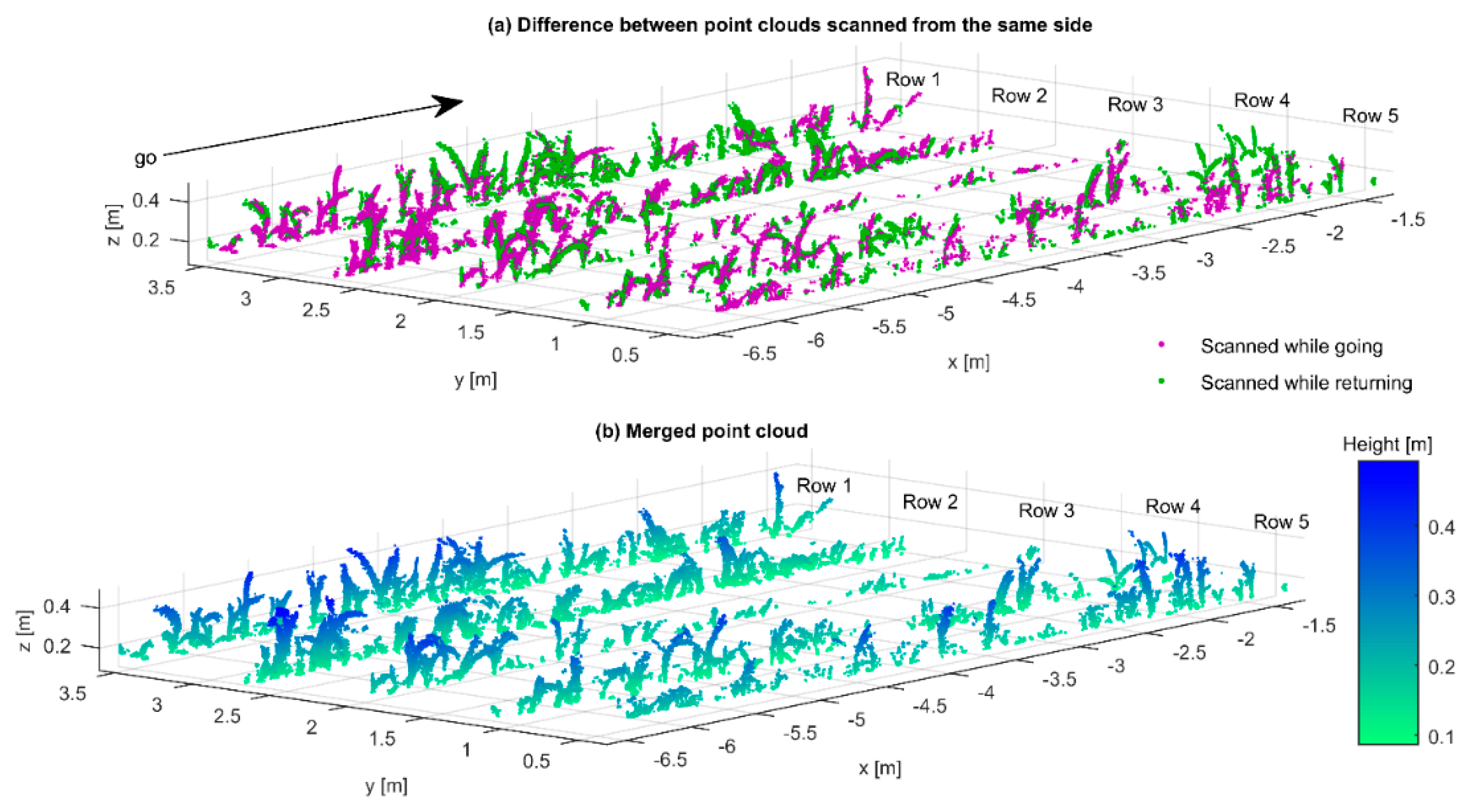
By merging two point clouds reconstructed from scans taken from the same side (see Figure 8a), meaning that the robotic platform drove in the same path going and then returning, the advantage is that the maize plants are well defined in their 3-D morphology, as seen in Figure 8b, but leaves from the other side are theoretically incomplete. However, the results of Table 2 showed that the RMSE and MAPE were 203 cm2 and 7.8%, respectively. These errors in the estimation of the LA were not very different from the ones obtained by merging four point clouds. One explanation could be related to the optimal position of the TOF camera and its inherent light volume technique that acquires dense information in a single shot. Vázquez et al. [8], in their previous research, emphasized the need to test the data acquisition by placing the camera in a side-view position in order to obtain more data about the plant stem due to occlusion. However, for the purpose of this research, the side-view position would not provide enough data of the leaf surface; therefore, the camera pose used was the most appropriate for estimating the leaf area. The relatively high variability of Table 1 and Table 2 could be explained by a mixture of different factors such as hand measurement errors, complex architecture of maize plants, occlusion, plant movement during data acquisition, assembly errors that produced small differences when the reconstructed crop rows were merged, and manual trimming.
The other reconstruction was done by merging two maize row point clouds reconstructed when the robotic platform scanned the left side of the row while going, and the right side of the row while returning (see Figure 9a). In this case, the robotic platform turned to the adjacent path in the headland. The theoretical advantage of this approach was that there were fewer hidden leaves that were not hit by the active sensing system of the TOF, camera compared to the previous one scanned from the same side. However, as seen in Table 3, the average RMSE and MAPE were 1059 cm2 and 32.3%, respectively. This high error could be explained by the poor continuity on the leaf point clouds due to the different 3-D perspective views of the opposing scans. This pattern can be seen in Figure 9a,b, where the leaf of the plant (x = −6.6, y = 2.7, z = 0.4) has some discontinuities.

4. Conclusions

A low-cost 3-D TOF camera was used to acquire 3-D data with the use of sensor fusion that tracked the pose of the camera with high precision. The results demonstrated that it was possible to estimate the LA based on the reconstructed surface (meshes) of maize rows by merging point clouds generated from different 3-D perspective views. The difference between generating the point clouds by scanning the crop row from two sides was very apparent in the resulting average MAPE of 7.8% and 29.8%, respectively. Therefore, even if two point clouds were aligned and merged in both cases, the continuity of the point cloud made a considerable difference in the LA estimation. The alignment and merge of four point clouds resulted in an average MAPE of 8.8% which was not very different from the one scanned from one side of the crop row. Therefore, although more information was obtained by merging the four point clouds, the one-side scanned provided a simpler approach for LA estimation. A future research direction should go into automating the manual estimations by automatically setting the point density parameter in order to avoid the manual trimming. Additionally, more research needs to be done with the LAI parameter estimation. High-throughput phenotyping for large greenhouses and open field (if the measurements are performed on cloudy or low sunlight intensity days) is a future application for this system. Potential environmental difficulties during the data acquisition campaign such as dust, rain, direct sunlight, etc., can be avoided by embedding the TOF camera into a protective casing, properly designed to protect the sensor without interfering with its operation.
The current limitation of the system is that it relies on a relatively expensive robotic platform and positioning system; however, a less expensive robotic platform and positioning system are already feasible. Commercial robotic systems for agricultural applications such as weeding are already available (NAIO, Deepfield Robotics), even though their energy consumption is high and thus their working-time limited. The commercial possibilities of a scout robot are better since the robot’s task can be executed while navigating, when the automatic data processing can be carried out.

Author Contributions

M.V.-A. and D.R. conducted the data analysis supported by D.S.P. and M.G.-I. M.V.-A., D.R., and M.G.-I. conducted all the field experiments supervised and guided by H.W.G.

Funding

The project was conducted at the Max-Eyth Endowed Chair (Instrumentation & Test Engineering) at Hohenheim University (Stuttgart, Germany), which is partly grant funded by the Deutsche Landwirtschafts-Gesellschaft e.V. (DLG).

Acknowledgments

The authors gratefully acknowledge Hiroshi Okamoto and Marlowe Edgar C. Burce for contributing with helpful comments on this research paper. In addition, the authors would like to thank the Deutscher Akademischer Austauschdienst (DAAD) and the Mexican Council of Science and Technology (CONACYT) for providing a scholarship for M.V.-A.

Conflicts of Interest

The authors declare no conflict of interest.

References

  1. Lambert, R.J.; Mansfield, B.D.; Mumm, R.H. Effect of leaf area on maize productivity. Maydica 2014, 59, 58–64. [Google Scholar]
  2. Diago, M.P.; Correa, C.; Millán, B.; Barreiro, P.; Valero, C.; Tardaguila, J. Grapevine yield and leaf area estimation using supervised classification methodology on RGB images taken under field conditions. Sensors 2012, 12, 16988–17006. [Google Scholar] [CrossRef] [PubMed] [Green Version]
  3. Hosoi, F.; Nakabayashi, K.; Omasa, K. 3-D modeling of tomato canopies using a high-resolution portable scanning lidar for extracting structural information. Sensors 2011, 11, 2166–2174. [Google Scholar] [CrossRef] [PubMed] [Green Version]
  4. Kazmi, W.; Bisgaard, M.; Garcia-Ruiz, F.; Hansen, K.D.; la Cour-Harbo, A. Adaptive Surveying and Early Treatment of Crops with a Team of Autonomous Vehicles. In Proceedings of the 5th European Conference on Mobile Robots ECMR, Orebro, Sweden, 7–9 September 2011; pp. 253–258. [Google Scholar]
  5. Bréda, N.J.J. Ground-based measurements of leaf area index: A review of methods, instruments and current controversies. J. Exp. Bot. 2003, 54, 2403–2417. [Google Scholar] [CrossRef] [PubMed]
  6. Vázquez-Arellano, M.; Griepentrog, H.W.; Reiser, D.; Paraforos, D.S. 3-D imaging systems for agricultural applications—A review. Sensors 2016, 16, 618. [Google Scholar] [CrossRef] [PubMed]
  7. Vázquez-Arellano, M.; Reiser, D.; Paraforos, D.S.; Garrido-Izard, M.; Burce, M.E.C.; Griepentrog, H.W. 3-D reconstruction of maize plants using a time-of-flight camera. Comput. Electron. Agric. 2018, 145, 235–247. [Google Scholar] [CrossRef]
  8. Vázquez-Arellano, M.; Paraforos, D.S.; Reiser, D.; Garrido-Izard, M.; Griepentrog, H.W. Determination of stem position and height of reconstructed maize plants using a time-of-flight camera. Comput. Electron. Agric. 2018, 154, 276–288. [Google Scholar] [CrossRef]
  9. Andújar, D.; Dorado, J.; Fernández-Quintanilla, C.; Ribeiro, A. An approach to the use of depth cameras for weed volume estimation. Sensors 2016, 16, 972. [Google Scholar] [CrossRef] [PubMed]
  10. Jiang, Y.; Li, C.; Paterson, A.H. High throughput phenotyping of cotton plant height using depth images under field conditions. Comput. Electron. Agric. 2016, 130, 57–68. [Google Scholar] [CrossRef]
  11. Hämmerle, M.; Höfle, B. Mobile low-cost 3D camera maize crop height measurements under field conditions. Precis. Agric. 2017, 19, 630–647. [Google Scholar] [CrossRef]
  12. Hu, Y.; Wang, L.; Xiang, L.; Wu, Q.; Jiang, H. Automatic non-destructive growth measurement of leafy vegetables based on kinect. Sensors 2018, 18, 806. [Google Scholar] [CrossRef] [PubMed]
  13. Paulus, S.; Behmann, J.; Mahlein, A.K.; Plümer, L.; Kuhlmann, H. Low-cost 3D systems: Suitable tools for plant phenotyping. Sensors 2014, 14, 3001–3018. [Google Scholar] [CrossRef] [PubMed]
  14. Nakarmi, A.D.; Tang, L. Automatic inter-plant spacing sensing at early growth stages using a 3D vision sensor. Comput. Electron. Agric. 2012, 82, 23–31. [Google Scholar] [CrossRef]
  15. Chaivivatrakul, S.; Tang, L.; Dailey, M.N.; Nakarmi, A.D. Automatic morphological trait characterization for corn plants via 3D holographic reconstruction. Comput. Electron. Agric. 2014, 109, 109–123. [Google Scholar] [CrossRef]
  16. Alenyà, G.; Foix, S.; Torras, C. ToF cameras for active vision in robotics. Sens. Actuators A Phys. 2014, 218, 10–22. [Google Scholar] [CrossRef] [Green Version]
  17. Colaço, A.F.; Molin, J.P.; Rosell-Polo, J.R.; Escolà, A. Application of light detection and ranging and ultrasonic sensors to high-throughput phenotyping and precision horticulture: Current status and challenges. Hortic. Res. 2018, 5. [Google Scholar] [CrossRef] [PubMed]
  18. Reiser, D.; Garrido-Izard, M.; Vázquez-Arellano, M.; Paraforos, D.S.; Griepentrog, H.W. Crop row detection in maize for developing navigation algorithms under changing plant growth stages. In Proceedings of the Robot 2015, Second Iberian Robotics Conference, Lisbon, Portugal, 19–21 November 2015; pp. 371–382. [Google Scholar]
  19. Paraforos, D.S.; Reutemann, M.; Sharipov, G.; Werner, R.; Griepentrog, H.W. Total station data assessment using an industrial robotic arm for dynamic 3D in-field positioning with sub-centimetre accuracy. Comput. Electron. Agric. 2017, 136, 166–175. [Google Scholar] [CrossRef]
  20. EDF R&D, T. P. CloudCompare (Version 2.9.1) [GPL Software]. Available online: https://www.danielgm.net/cc/ (accessed on 15 August 2018).
  21. Besl, P.; McKay, N. A Method for Registration of 3-D Shapes. IEEE Trans. Pattern Anal. Mach. Intell. 1992, 14, 239–256. [Google Scholar] [CrossRef]
  22. Fischler, M.A.; Bolles, R.C. Random sample consensus: A paradigm for model fitting with applications to image analysis and automated cartography. Commun. ACM 1981, 24, 381–395. [Google Scholar] [CrossRef]
  23. Dewez, T.J.B.; Girardeau-Montaut, D.; Allanic, C.; Rohmer, J. Facets: A cloudcompare plugin to extract geological planes from unstructured 3d point clouds. Int. Arch. Photogramm. Remote Sens. Spat. Inf. Sci. ISPRS Arch. 2016, 41, 799–804. [Google Scholar] [CrossRef]
  24. Kazhdan, M.; Bolitho, M.; Hoppe, H. Poisson Surface Reconstruction. In Proceedings of the International Conference on Scale Space and Variational Methods in Computer Vision, Lège-Cap Ferret, France, 31 May–4 June 2015; pp. 525–537. [Google Scholar]
  25. Li, X.; Zaragoza, J.; Kuffner, P.; Ansell, P.; Nguyen, C.; Daily, H. Growth Measurement of Arabidopsis in 2.5D from a High Throughput Phenotyping Platform. In Proceedings of the 21st International Congress on Modelling and Simulation, Gold Coast, Australia, 29 November–4 December 2015; pp. 517–523. [Google Scholar]
  26. Kazhdan, M.; Hoppe, H. Screened Poisson Surface Reconstruction. ACM Trans. Graph. 2013, 32, 1–13. [Google Scholar] [CrossRef]
  27. Montgomery, E.G. Correlation studies in corn. Neb. Agric. Exp. Stn. Annu. Rep. 1911, 24, 108–159. [Google Scholar]
Figure 1. The robotic platform in the greenhouse, depicting the total station with the prism for positioning, the IMU for orientation, and the TOF camera and embedded computer for 3-D data acquisition.
Robotics 07 00063 g001
Figure 2. Maize seeding positions (+) and viewpoint represented by the camera plot. The viewpoint of the camera plot was set up as a reference to determine the left and right side of the crop row.
Robotics 07 00063 g002
Figure 3. Methodology for plan point cloud alignment and merge for LA estimation.
Robotics 07 00063 g003
Figure 4. Point cloud (a) registered and aligned, (b) merged, and (c) rasterized.
Robotics 07 00063 g004
Figure 5. 3-D surface reconstruction of plant point clouds using (a) Poisson surface reconstruction and (b) resulting mesh after trimming.
Robotics 07 00063 g005
Figure 6. (a) Rasterized point cloud used to generate the Poisson surface reconstruction (black mesh) and (b) the same point cloud with the manually trimmed surface.
Robotics 07 00063 g006
Figure 7. (a) All four point clouds merge and the (b) rasterization projected on the z-axis with a grid size of 1 cm2, and superimposed, the estimated LA depicted as a black mesh.
Robotics 07 00063 g007
Figure 8. Same side scanned point cloud (a) while going and returning and (b) after merging.
Robotics 07 00063 g008
Figure 9. Opposite direction scanned point cloud acquired (a) from the left and right side of the crop row and (b) after merging.
Robotics 07 00063 g009
Table 1. Alignment and merge of four point clouds scanned from both sides and directions.
DirectionCrop RowRasterized Crop Height (10 mm)
[cm2]
Poisson Surface Reconstruction
[cm2]
Ground Truth LA
[cm2]
RMSE
[cm2]
MAPE
Go left side, return left side, go right side, and return right side24713458041913899.2%
Go left side, return left side, go right side, and return right side317811895163426316%
Go left side, return left side, go right side, and return right side4217927772819421,4%
Average 2891308428812318.8%
Table 2. Alignment and merge of two point clouds scanned from the same side of the crop row.
DirectionCrop RowRasterized Crop Height (10 mm)
[cm2]
Poisson Surface Reconstruction
[cm2]
Ground Truth LA
[cm2]
RMSE
[cm2]
MAPE
Go right side and return right side12685261128242137.5%
Go left side and return left side22680409141911002.3%
Go left side and return left side3107717331634996%
Go left side and return left side416112332281948717.2%
Go left side and return left side51433176218791176.2%
Average 1897250526692037.8%
Table 3. Alignment and merge of two point clouds scanned from both sides with opposite directions.
DirectionCrop RowRasterized Crop Height (10 mm)
[cm2]
Poisson Surface Reconstruction
[cm2]
Ground Truth LA
[cm2]
RMSE
[cm2]
MAPE
Go left side and return right side2304731564750159433.5%
Go left side and return right side311912479185262733.8%
Go left side and return right side415604150319595529.8%
Average 193232613265105932.3%