Performance-Based Design of the CRS-RRC Schoenflies-Motion Generator


1
Department of Engineering, University of Ferrara, 44100 Ferrara, Italy
2
Raul Guenther laboratory of Applied Robotics, Department of Mechanical Engineering, Federal University of Santa Catarina, Florianópolis, SC 88040-900, Brazil
*
Author to whom correspondence should be addressed.
Robotics 2018, 7(3), 55; https://doi.org/10.3390/robotics7030055
Submission received: 22 July 2018
/
Revised: 8 September 2018
/
Accepted: 10 September 2018
/
Published: 15 September 2018
(This article belongs to the Special Issue Kinematics and Robot Design I, KaRD2018)
Abstract
:Rigid-body displacements obtained by combining spatial translations and rotations around axes whose direction is fixed in the space are named Shoenflies’ motions. They constitute a 4-dimensional (4-D) subgroup, named Shoenflies’ subgroup, of the 6-D displacement group. Since the set of rotation-axis’ directions is a bi-dimensional space, the set of Shoenflies’ subgroups is a bi-dimensional space, too. Many industrial manipulations (e.g., pick-and-place on a conveyor belt) require displacements that belong to only one Schoenflies’ subgroup and can be accomplished by particular 4-degrees-of-freedom (4-DOF) manipulators (Shoenflies-motion generators (SMGs)). The first author has recently proposed a novel parallel SMG of type CRS-RRC1. Such SMG features a single-loop architecture with actuators on the base and a simple decoupled kinematics. Here, firstly, an organic review of the previous results on this SMG is presented; then, its design is addressed by considering its kinetostatic performances. The adopted design procedure optimizes two objective functions, one (global conditioning index (GCI)) that measures the global performance and the other (CImin) that evaluates the worst local performance in the useful workspace. The results of this optimization procedure are the geometric parameters’ values that make the studied SMG have performances comparable with those of commercial SMGs. In addition, a realistic 3D model that solves all the manufacturing doubts with simple and cheap solutions is presented.
1. Introduction
Shoenflies’ motions are rigid-body displacements obtained by combining spatial translations and rotations around axes with a fixed direction. They constitute a 4-dimensional (4-D) subgroup, named Shoenflies’ subgroup, of the 6-D displacement group [1,2]. Since the set of rotation-axis’ directions is a bi-dimensional space, the set of Shoenflies’ subgroups is a bi-dimensional space, too. Many industrial manipulations (e.g., pick-and-place on a conveyor belt) require displacements that belong to only one Schoenflies’ subgroup and can be accomplished by particular 4-degrees-of-freedom (4-DOF) manipulators, named Shoenflies-motion generators (SMGs) [3].
The serial robot SCARA, presented in 1981, is the most known SMG, but many alternative serial architectures can be conceived [3]. The main drawback of serial architectures is the need of actuating joints that connect mobile links, which brings to increase the mobile masses and, simultaneously, to reduce the dynamic performances. Parallel architectures can solve this issue and parallel SMGs have been presented (see, for instance [4,5,6,7,8,9,10,11,12]), too. Most of the proposed parallel SMGs feature four limbs (e.g., [5,6,7,9,12]) and one actuator per limb located on the base. Other parallel SMGs are simply obtained by adding a double Cardan shaft (i.e., a limb of RUPUR type), which connects the base to the platform, in a translational parallel manipulator.
The main drawback of parallel SMGs is their complex multi-loop structure that drastically reduces their workspace, usually brings cumbersome kinematics and control algorithms, and, often, does not allow a full rotation of the end effector (platform). Nevertheless, adopting two-limbed (i.e., single-loop) architectures with serial [4,13] or hybrid [8,11] limbs with two actuators per limb reduces the structure complexity while keeping the actuators on the base. Some design tricks [14,15] can yield end-effector’s full rotations, and some architectures [12,13] can give the possibility of decoupling position and orientation (decoupled kinematics), which allows simpler and more intuitive control strategies. Moreover, not-overconstrained architectures [4] make it possible to avoid jamming without using small tolerances during manufacturing.
The first author has recently proposed a novel not-overconstrained parallel SMG of type CRS-RRC [13]. Such SMG features a single-loop architecture with actuators on the base and a simple decoupled kinematics. Here, firstly, an organic review of the previous results on this SMG is presented; then, its design is addressed by considering its kinetostatic performances. This design procedure will yield a realistic 3D model that solves all the manufacturing doubts with simple and cheap solutions.
2. Notations and Background
Figure 1 shows the SMG of type CRS-RRC presented in [13]. The axes of the R and C pairs are all parallel. The platform is connected to the base through two limbs: one of type CRS and the other of type RRC. The actuated C pair of the CRS limb is obtained by mean of a PR chain with the sliding direction of the P pair parallel to the axis of the R pair. Such a kinematic chain can be actuated by keeping the motors on the base and using commercial components as shown in Figure 2. Also, the second actuated R pair of the RRC limb can be moved from the base by simply using a toothed-belt transmission.
With reference to Figure 1, Obxbybzb is a Cartesian reference fixed to the base; the direction of the zb coordinate axis is the same as the R and C pair axes. In the platform, ap is the constant distance of the center of the S pair from the axis of the passive C pair and is equal to the length of the segment ApA2. Op is the reference point of the platform, and h is the length of the segment ApOp. The coordinates, (xp, yp, zp)T, of Op, measured in Obxbybzb, locate the position of the platform; whereas, the angle, φ, between the segment ApA2 and a line parallel to xb and passing through Ap uniquely determines the platform orientation. In the CRS limb, point B2 lies on the axis of the actuated C pair and is fixed to the output link of the C pair. The linear variable of the actuated C pair is the signed distance, d, of B2 from Ob. The plane parallel to the xbyb plane and passing through B2 intersects the axis of the passive R pair at D2, the axis of the passive C pair at Ap, and the axis parallel to the zb axis and passing through the center of the S pair at A2. a3 and a4 are the lengths of the segments B2D2 and D2A2, respectively; whereas, θ3 and θ4 are the angular variable of the actuated C pair and the joint variable of the passive R pair, respectively. The point Ap is fixed to the platform. In the RRC limb, the actuated-joint variables are θ1 and θ2. The xbyb plane intersects the axis of the R pair adjacent to the base at B1, the axis of the other R pair at D1, and the axis of the passive C pair at A1. a0, a1 and a2 are the lengths of the segments ObB1, B1D1 and D1A1, respectively. The RRC limb constrains the platform to perform Schoenflies motions with rotation axis parallel to the zb axis; whereas, the CRS limb controls the coordinate zp of point Op through its linear variable, d, and, independently, the platform orientation through its angular variable, θ3.
According to these notations, the 4-tuples q = (θ1, θ2, θ3, d)T and κ = (xp, yp, zp, φ)T collect the actuated-joint (input) variables and the platform-pose (output) variables, respectively. The inspection of Figure 1 yields the following closure equations
xp = a0 + a1 cos θ1 + a2 cos (θ1 + θ2),
yp = a1 sin θ1 + a2 sin (θ1 + θ2),
zp = d − h
(xp + ap cos φ − a3 cos θ3)2 + (yp + ap sin φ − a3 sin θ3)2 = a42
If q is assigned (direct position analysis (DPA)), Equation (1a–c) yield a unique platform position; whereas, Equation (1d) yields two platform orientations (i.e., the DPA has two solutions that share the same platform position). Vice versa, if κ is assigned (inverse position analysis (IPA)), Equation (1c) yields only one value for d; whereas, Equation (1a,b,d) yield at most four values for (θ1, θ2, θ3) which can be computed through explicit formulas (see [13] for the proof and the formulas), that is, the IPA has at most four solutions which share the same value of d.
The time derivatives of Equation (1a–d) yield
where mx = xp + ap cos φ − a3 cos θ3 and my = yp + ap sin φ − a3 sin θ3.
Since the RRC limb forbids the platform to perform displacements that do not belong to the above-mentioned Schoenflies’ subgroup, the studied SMG has no constraint singularities2 and uniquely identifies the platform twist. As a consequence, Equation (2a–d) are sufficient to relate the platform twist to the actuated-joint rates, , that is, they are the instantaneous input-output relationship (InI/O).
The InI/O of a manipulator is a linear mapping between platform twists and actuated-joint rates whose coefficient matrices (Jacobians) only depend on the configuration of the manipulator. The configurations (singularities) where these Jacobians have not full rank make the linear mapping not bijective and have relevant kinetostatic implications [17,18,19,20,21].
According to the above-deduced InI/O, if is assigned, is always uniquely determined, but is not determined when the segments A2D2 and A2Ap are aligned (i.e., a parallel singularity3 occurs). In addition, if is assigned, only two geometric conditions make one or more actuated-joint rates undetermined (i.e., a serial singularity4 occurs): (i) the 2-tuple is not determined when the segments A1D1 and D1B1 are aligned, and (ii) is not determined when the segments A2D2 and D2B2 are aligned.
3. Workspace Analysis
According to the adopted notations, the geometric constants of the CRS-RRC SMG, which affect the SMG behavior, are a0, a1, a2, a3, a4, ap, and h (Figure 1). Two of the authors, in [16], analyzed some workspace characteristics of this SMG. Such analysis brought to size some of those constants. This section summarizes and reviews the results deduced in [16].
If the two actuated R pairs of the RRC limb and the linear variable, d, of the actuated C pair are locked (i.e., by keeping zp and A1 fixed), the segments B2Ap (=ObA1 = ), B2D2 (=a3), D2A2 (=a4), and ApA2 (=ap) behave like frame, input link, coupler, and follower, respectively, of a four-bar linkage. θ3 and φ are input and output variables, respectively, of this four-bar linkage, and the singularities of this four-bar correspond to the above-identified parallel singularity and serial singularity (ii). If this four-bar satisfies Grashof’s law [22] and ApA2 is the shortest bar, the platform can perform a complete rotation (i.e., the angle φ has no limitation). Nevertheless, only a double-crank four-bar can guarantee a full control of the platform rotation.
Let p and p denote the position vector (A1–Ob) and its magnitude (=), respectively. From an analytic point of view, the four-bar is a double-crank (i.e., the platform can perform a complete rotation fully controlled by θ3) if and only if
(ap + p) ≤ (a3 + a4),
|ap − p| ≥ |a3 − a4|,
p = min{p, a3, a4, ap}.
Inequalities (3a,b) impose that the platform can perform a full rotation and condition (3c) make the four-bar linkage double-crank.
Since there is no reason to have a3 different from a4 and a possible scaling factor does not affect the analysis, the choice a3 = a4 = 1 length unit (l.u.) is adopted. With this assumption, inequality (3b) become |ap − p| ≥ 0 and is identically satisfied; whereas, inequality (3a) and condition (3c) become
p ≤ ap ≤ 2 − p
The blue area of Figure 3 indicates the values of the 2-tuple (p, ap) that satisfy inequalities (4). Figure 3 shows that the maximum value, pGr, that p can assume depends only on ap: when the values of ap increase, pGr increases for ap ≤ 1 and, then, decreases for ap > 1. The maximum value of pGr is 1 l.u. and is obtained with ap = 1 l.u. Since pGr is the radius (see Figure 1) of the circle centered at Ob that is the region (double-crank region) where A1 must be located to have a double-crank linkage, the choice ap = 1 l.u. is adopted to maximize the double-crank region.
Let Δd (=dmax − dmin) be the maximum linear stroke of the actuated C pair. The reachable workspace [23] referred to Op is a right cylinder with height Δd, whose cross section is the intersection between two circles: one centered at Ob with radius a3 + a4 + ap and the other centered at B1 with radius a1 + a2. The cross section of the reachable workspace is maximized if the smaller circle is located inside the other, that is, if
or
a0 + a1 + a2 ≤ a3 + a4 + ap
a3 + a4 + ap ≤ a1 + a2 − a0.
In addition, if such section contains the double-crank region, the dexterous workspace [23] referred to Op is maximum, and it is equal to a right circular cylinder obtained by translating the double-crank region along the zb axis of Δd. This condition is satisfied if
pGr + a0 ≤ a1 + a2,
|a1 − a2| ≤ a0 − pGr,
pGr ≤ a3 + a4 + ap.
At the border of the double-crank region (i.e., for p = pGr), the four-bar linkage can still make the platform perform a complete rotation, but the linkage encounters two times the parallel singularity condition during the platform rotation. Since the integrity of parallel manipulators can be preserved only by keeping them work out and far from parallel singularities, a safe free-from-singularity dexterous workspace requires p << pGr.
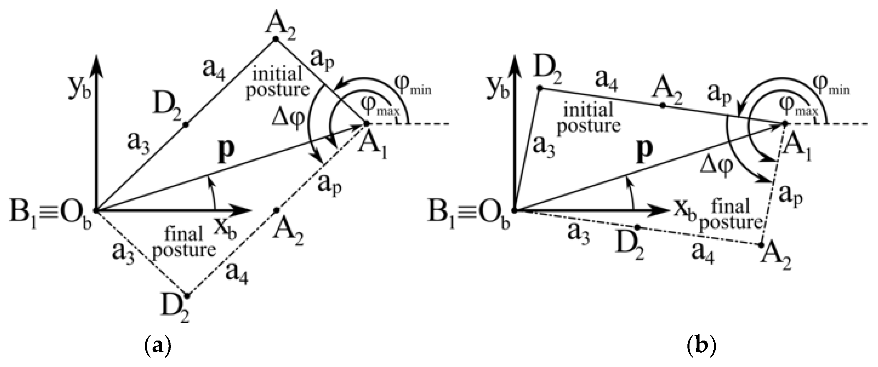
Outside the double-crank region (i.e., for p > pGr), the four-bar linkage does not satisfy Grashof’s law any longer; as a consequence, it can only be a rocker-rocker four-bar linkage and the rotation range, Δφ, of the platform is limited. Figure 4 shows the above-defined not-Grashof four-bar linkage at the configurations corresponding to the extreme values of φ. In a rocker-rocker four-bar, the whole Δφ is swept by moving from a serial singularity (ii) to a parallel singularity (Figure 4a) or vice versa (Figure 4b). In both the cases, Δφ does not change, but the configurations the mechanism passes through are different. The analysis of Figure 4 gives the following simple analytic formula for Δφ
Formula (7) highlights that Δφ depends only on p (i.e., the direction of the position vector p does not affect Δφ) and decreases when p increases. This symmetry with respect to the zb axis and the fact that the decrease of Δφ with the increase of p is not sharp [16] make wide regions of the reachable workspace that are out of the double-crank region usable for manipulation tasks that need not a complete platform rotation.
4. Kinetostatic-Performance Analysis and Dimensional Synthesis
The previous sections brought to choose a3 = a4 = ap = 1 l.u. All the other geometric constants (i.e., a0, a1, a2, and h) can be used to match the adoption of a useful workspace adequate to industrial tasks with satisfactory kinetostatic properties. Even though the CRS-RRC SMG can perform some tasks outside the above-defined dexterous workspace, the choice of the useful workspace has to take into account the generality of the industrial tasks of an SMG. Consequently, in this case, the useful workspace is chosen as a right circular cylinder with axis passing through Ob (see Figure 1) and radius, puw, that satisfies the condition puw << pGr, which makes it coincide with a safe free-from-singularity dexterous workspace.
The determination of puw can be done by imposing that the transmission angle [22,24], μ, of the above-defined four-bar linkage has an acceptable value during the platform rotation. In general, tasks that require the application of relevant forces to the gripper during motion (e.g., machining tasks like drilling) need values of |μ − 90| (°) lower than 50° and low friction in the kinematic pairs. Other manipulation tasks with reduced force interaction can accept |μ − 90| values lower than 70°; whereas, when force interaction is not present (e.g., pick-and-place tasks) |μ − 90| could be even larger than 70°. The formulas (see [24]) that give the minimum, μmin, and the maximum, μmax, transmission angles, when particularized to the studied case, become (μ ∈ [0°, 180°])
which, for a3 = a4 = ap = 1 l.u., give the diagrams of Figure 5.
Figure 5 shows that |μ − 90| ≤ 50° corresponds to p = 0.317 and |μ − 90| ≤ 70° corresponds to p = 0.653; whereas, for p = 0.75, |μ − 90| exceeds 70° only in a small neighborhood of μmin which is equal to 14.4°.
Since SMGs are mainly employed in pick-and-place tasks, the choice puw = 0.75 is adopted by confining the force interaction tasks in region with p ≤ 0.653 or with p ≤ 0.316 according to the type of task.
A commercial SMG is the pickstar YS02N of Kawasaki [25]. Its useful workspace is a right circular cylinder with a base radius of 300 mm and a height of 200 mm. Hereafter, this right circular cylinder is chosen as useful workspace for the dimensional synthesis of the CRS-RRC SMG. This choice together with the previous choice puw = 0.75 yield 1 (l.u.) = 400 mm, that is, a3 = a4 = ap = 400 mm.
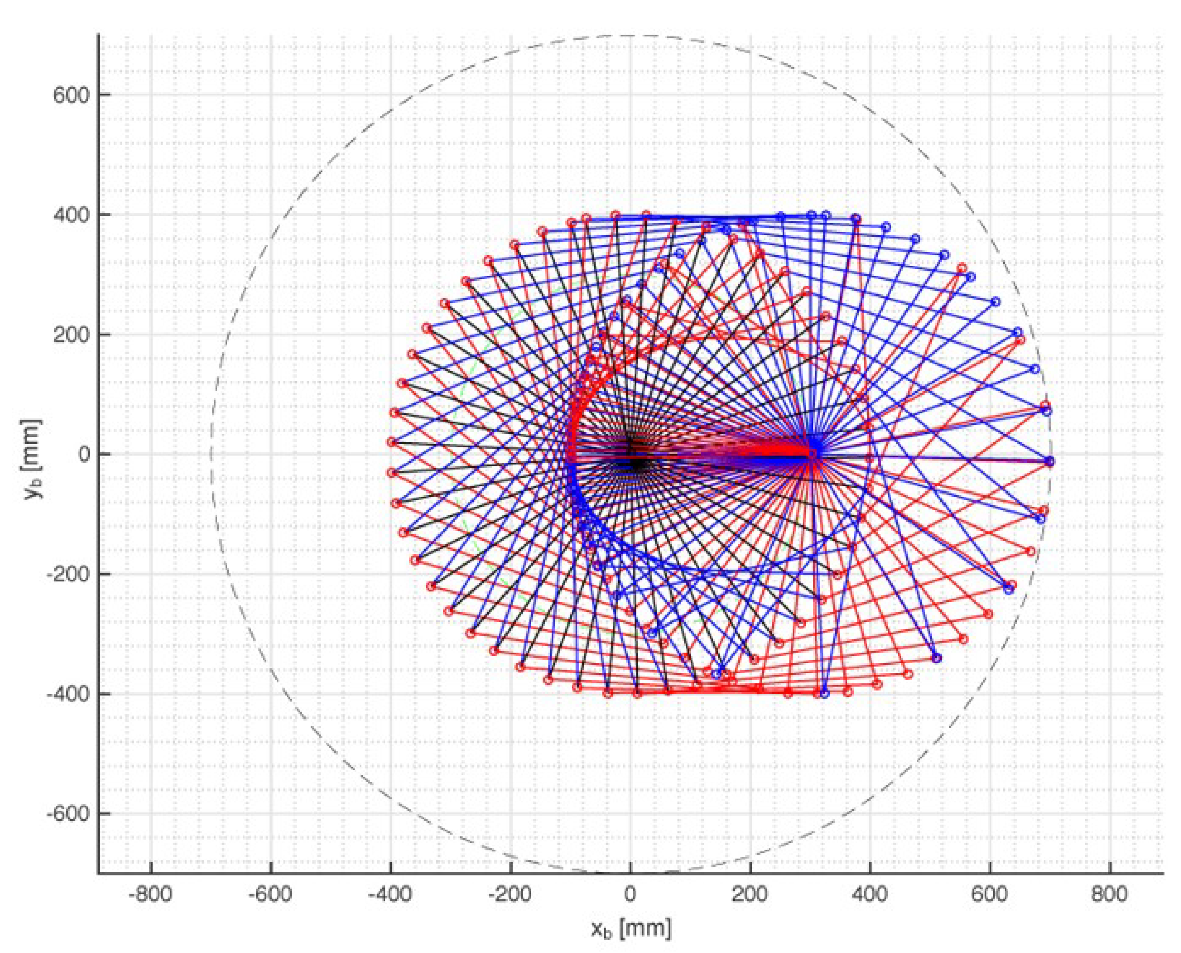
Figure 6 shows the region of the xbyb plane swept by the above-defined four-bar linkage with a3 = a4 = ap = 400 mm when point A1 is moved along the xb axis from Ob (i.e., A1 = (0, 0)) to the border of the useful workspace (i.e., A1 = (300, 0) mm). The whole region swept by the four-bar when the direction of the motion of A1 changes can be obtained by making the region highlighted in Figure 6 rotate around Ob in the xbyb plane. Such rotation yields a circle with a radius of 700 mm. Consequently, by taking into account the physical sizes of the links, the choice a0 = 800 mm is adopted in order to avoid interferences between the frame and the four-bar during motion.
4.1. Measure of the Kinetostatic Performances
The matrix form of system (2) (i.e., of the InI/O) is
with
Kinetostatic performances of manipulators can be evaluated by using indices built by using the Jacobians Jk and Jq of Equation (9). Two of these indices are the “conditioning index” (CI) [26] of the matrix J = (Jq)−1Jk, which is defined as the inverse of the condition number of J, and its average value on the useful workspace, named “global conditioning index” (GCI). The computation of the CI and GCI needs that the entries of the Jacobians Jk and Jq be homogeneous [9,27,28,29]. Jacobian homogenization can be obtained with the introduction of a characteristic length, λ, through a change of variables [27], even though which λ should be used is an open problem.
In the studied case, the introduction of the new homogeneous variables and into Equation (9) yields
where Jh = (Jqh)−1Jkh with
Jh is a homogeneous Jacobian with dimensionless entries. The condition number, χ, of Jh is, by definition, where stands for any matrix norm of the argument, if the Frobenius norm [21] is adopted . Consequently, the conditioning index, CI = 1/χ, depends both on the SMG configuration and on the geometric constants a1 and a2 that have not been determined, yet. The CI ranges from 0, at parallel singularities to 1 at isotropic configurations (i.e., SMG configurations where Jh is proportionate to the identity matrix), which are the farthest from parallel singularities. The CI is a local index that measures the kinetostatic performance of the SMG at a configuration; whereas, the GCI (i.e., its average value on the useful workspace) gives a score to the kinetostatic performance of the SMG and could be used to compare different manipulators.
Optimizing the kinetostatic performances of a manipulator by using the CI and the GCI means determining the available geometric constants (in this case, a1 and a2) so that the minimum value, CImin, of the CI and the GCI are as high as possible for that architecture. Such optimization is presented in the following subsection.
4.2. Dimensional Synthesis
The admissible values of a1 and a2 must satisfy inequalities (6a,b) with a0 = 800 mm and pGr = ap = 400 mm. Moreover, a reasonable choice for the RRC limb would be a2 ≤ a1. All these inequalities are satisfied in the region highlighted in blue of Figure 7.
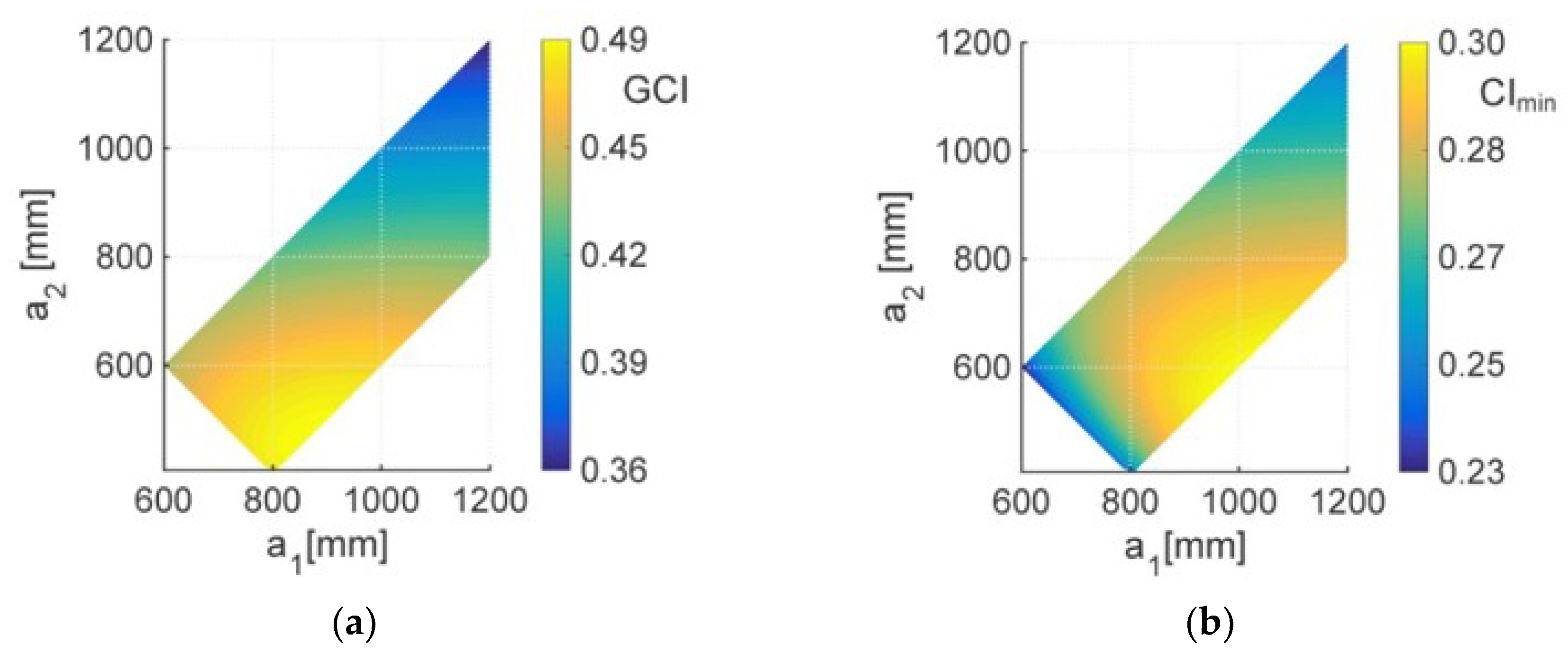
By setting λ = 400 mm (i.e., equal to the length of ap, a3 and a4 and to the arithmetic mean of the diameter and the height of the useful workspace), a numerical algorithm has been used to compute the GCI and the CImin referred to the useful workspace for each admissible values of (a1, a2). The results of these computations are shown in Figure 8.
The analysis of the GCI values displayed in Figure 8a reveals that the maximum GCI is equal to 0.48795 and is obtained with a1 = 869 mm and a2 = 469 mm, which correspond to CImin = 0.28682 (Figure 8b). Also, Figure 8a shows that the maximum GCI falls in a smooth region (more or less flat) which allows large variation of (a1, a2) with small reductions of the GCI.
On the other side, the analysis of the CImin values displayed in Figure 8b reveals that the maximum CImin is equal to 0.29806 and is obtained with a1 = 993 mm and a2 = 593 mm, which correspond to GCI = 0.4763 (Figure 8a). Moreover, Figure 8b shows that also the maximum CImin falls in a smooth region (more or less flat). These results bring to choose a1 = 950 mm and a2 = 600 mm which correspond to a good compromise with GCI = 0.482 and CImin = 0.29743 that are values near enough to their maxima. The chosen values of a1 and a2 yield the minimum CI values at each A1 position inside the useful workspace shown in Figure 9. Figure 9 highlights that most of the useful workspace has CI ≥ 0.45, which makes the CI distribution acceptable.
4.3. The 3D Model
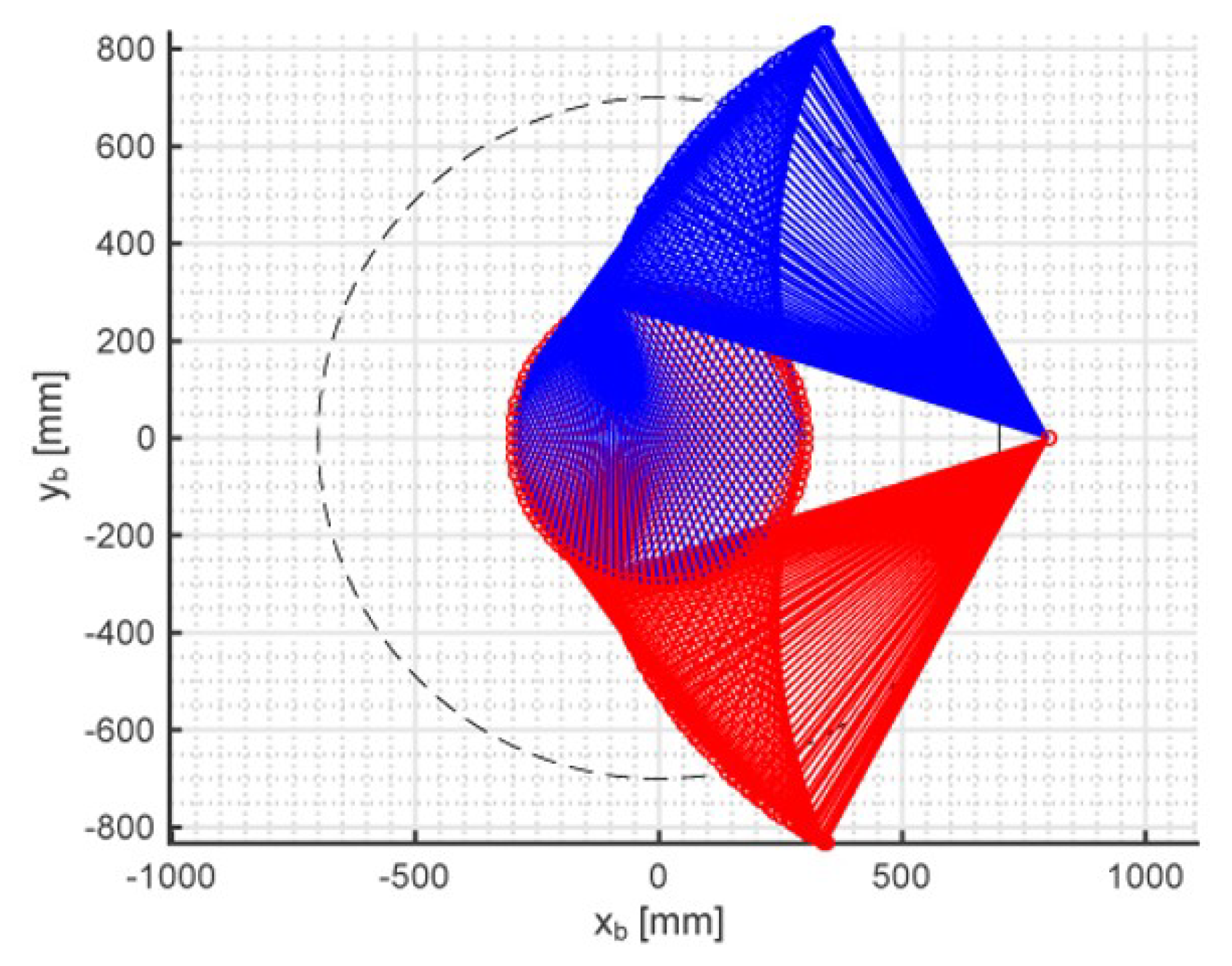
The dimensional synthesis, with useful workspace assigned as a right circular cylinder with a radius of 300 mm and a height of 200 mm, brought to choose the following values of the geometric constants: a0 = 800 mm, a1 = 950 mm, a2 = 600 mm, a3 = 400 mm, a4 = 400 mm, and ap = 400 mm. Figure 10 shows the region of the xbyb plane swept by the RRC limb, with a0 = 800 mm, a1 = 950 mm, and a2 = 600 mm, when point A1 is moved on the whole circular boundary of the useful workspace and the limb is assembled in either of the two assembly modes the IPA identifies [13]. The analysis of Figure 10 highlights that no link interference occurs with the chosen geometric data. By combining Figure 6 and Figure 10 the overall region of the xbyb plane that is swept by both the limbs is obtained. Figure 11 shows such region.
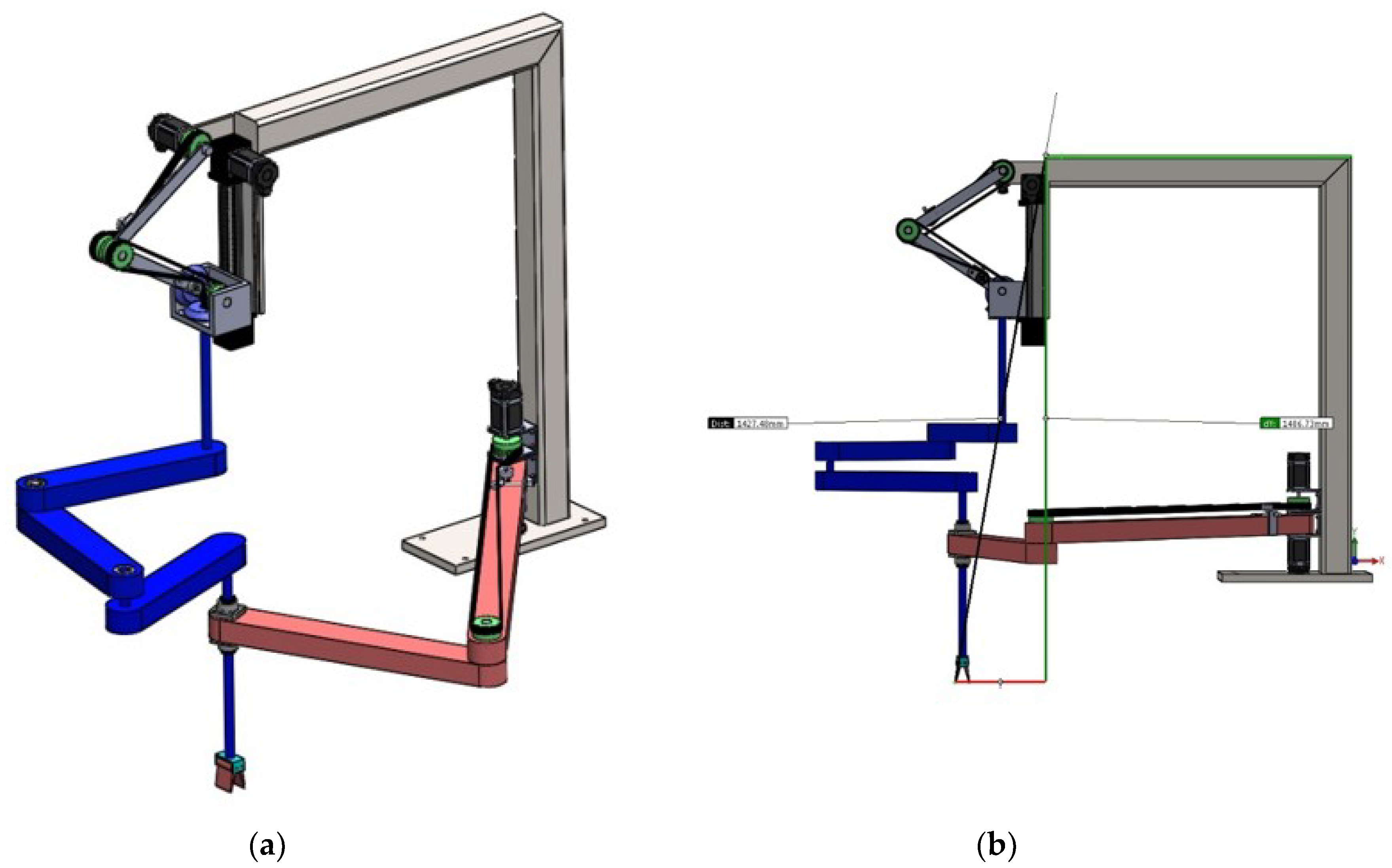
In order to solve all the doubts about the actual feasibility of the machine, a CAD model of the CRS-RRC SMG has been built with the chosen geometric data. Figure 12 shows the 3D view (Figure 12a) and the lateral view (Figure 12b) of this model. Such model has an L-shaped base, only commercial actuators that are all mounted on the base, rolling bearings in all the R pairs to avoid jamming of the above-defined four-bar linkage at low transmission angles, a spherical roller bearings that implements the S-pair constraint5, and a linear ball bearing that implements the constraint of the passive C-pair. The bevel gearbox and the toothed belts (Figure 2 and Figure 12) are commercial products, too.
5. Summary of the Results and Discussion
The kinematic analysis [13] of the CRS-RRC SMG showed that both the DPA and IPA are solvable with simple and explicit formulas, and that platform’s translation and rotation are decoupled. Therefore, the control algorithms are easy to implement and require very low computation time, which makes it possible to build a fast online control system.
The above-reviewed workspace analysis (see also Ref. [16]) highlighted that the reachable workspace has axially-symmetric properties. In particular, a safe free-from-singularity dexterous workspace, which is a right circular cylinder, is easy to identify in a wider region of the reachable workspace where the platform can perform complete rotations. Moreover, parallel singularities occur only for two known platform orientations and, in the reachable workspace, they are located on a circle that is the boundary of the dexterous workspace. Thus, the platform can pass through the parallel-singularity locus simply by changing its orientation and, if necessary, can accomplish particular tasks in region where the platform rotation is bounded.
The kinetostatic analysis based on the transmission angle and the conditioning index revealed that the machine can be so dimensioned that the GCI and the CImin are acceptable in a useful workspace, equal to those of commercial SMGs, with transmission angles adequate to the generality of industrial tasks.
The CAD model of the CRS-RRC SMG showed that its manufacture needs only commercial components. This result proves the actual feasibility of the machine with cheap production processes. Moreover, it highlights that the L-shaped base when fixed on a rotating frame allows an easy way for setting up the machine with respect to different machining planes (e.g., belt conveyors).
6. Conclusions
Kinetostatic indices have been used to complete the dimensional synthesis of the SMG of type CRS-RRC previously presented by the first author. In particular, a safe free-from-singularity useful workspace equal to that of a commercial SMG (the pickstar YS02N of Kawasaki [25]) has been chosen and all the geometric constants of this machine have been determined so that the minimum CI and the GCI are maximized.
Then, the so-determined geometric constants have been used to build a realistic 3D model that involves only commercial components, and implements an original architecture for actuated C pairs that brings all the actuators on the frame.
The obtained results positively close the validation of the machine concept and open to the structural and dynamic analyses/checks necessary to match static and dynamic requirements for an assigned payload. These analyses together with stiffness and accuracy analyses are the next steps of this project.
Author Contributions
Data curation, M.C. and H.S.; Formal analysis, R.D.G.; Funding acquisition, R.D.G. and H.S.; Investigation, R.D.G., M.C. and H.S.; Methodology, R.D.G.; Project administration, R.D.G.; Software, M.C.
Funding
This work has been developed at the Laboratory of Advanced Mechanics (MECH-LAV) of Ferrara Technopole, supported by FAR2017 UNIFE funds, by Regione Emilia Romagna (District Councillorship for Productive Assets, Economic Development, Telematic Plan) POR-FESR 2007-2013, Attività I.1.1, and by CNPq—Conselho Nacional de Desenvolvimento Científico e Tecnológico (National Council for Scientific and Technological Development), Brazil.
Conflicts of Interest
The authors declare no conflict of interest. The funders had no role in the design of the study; in the collection, analyses, or interpretation of data; in the writing of the manuscript, and in the decision to publish the results.
References
- Hervé, J.M. The Lie group of rigid body displacements, a fundamental tool for mechanism design. Mech. Mach. Theory 1999, 34, 719–730. [Google Scholar] [CrossRef]
- Bottema, O.; Roth, B. Theoretical Kinematics; Courier Dover Publications: Amsterdam, The Netherlands, 1979; ISBN 0-444-85124-0. [Google Scholar]
- Lee, C.-C.; Hervé, J.M. Type Synthesis of Primitive Schoenflies-Motion Generators. Mech. Mach. Theory 2009, 44, 1980–1997. [Google Scholar] [CrossRef]
- Lee, C.-C.; Hervé, J.M. Isoconstrained Parallel Generators of Schoenflies Motion. ASME J. Mech. Robot. 2011, 3, 021006. [Google Scholar] [CrossRef]
- Pierrot, F.; Company, O. H4: A New Family of 4-dof Parallel Robots. In Proceedings of the IEEE/ASME International Conference on Advanced Intelligent Mechatronics (AIM’99), Atlanta, GA, USA, 19–23 September 1999; pp. 508–513. [Google Scholar]
- Krut, S.; Company, O.; Benoit, M.; Ota, H.; Pierrot, F. I4: A new parallel mechanism for SCARA motions. In Proceedings of the 2003 International Conference on Robotics and Automation, Taipei, Taiwan, 14–19 September 2003; pp. 1875–1880. [Google Scholar]
- Nabat, V.; de la O. Rodriguez, M.; Company, O.; Krut, S.; Pierrot, F. Par4:very high speed parallel robot for pick-and-place. In Proceedings of the 2005 IEEE/RSJ International Conference on Intelligent Robots and Systems, Edmonton, AB, Canada, 2–6 August 2005; pp. 553–558. [Google Scholar]
- Angeles, J.; Caro, S.; Khan, W.; Morozov, A. The Design and Prototyping of an Innovative Schoenflies Motion Generator. Proc. IMechE-Part C J. Mech. Eng. 2006, 220, 935–944. [Google Scholar] [CrossRef] [Green Version]
- Li, Z.; Lou, Y.; Zhang, Y.; Liao, B.; Li, Z. Type Synthesis, Kinematic Analysis, and Optimal Design of a Novel Class of Schoenflies-Motion Parallel Manipulators. IEEE Trans. Autom. Sci. Eng. 2013, 10, 674–686. [Google Scholar]
- Kong, X.; Gosselin, C.M. Type Synthesis of 3T1R 4-dof Parallel Manipulators Based on Screw Theory. IEEE Trans. Robot. Autom. 2004, 20, 181–190. [Google Scholar] [CrossRef]
- Company, O.; Pierrot, F.; Nabat, V.; Rodriguez, M. Schoenflies Motion Generator: A New Non Redundant Parallel Manipulator with Unlimited Rotation Capability. In Proceedings of the 2005 IEEE International Conference on Robotics and Automation, Barcelona, Spain, 18–22 April 2005; pp. 3250–3255. [Google Scholar]
- Richard, P.-L.; Gosselin, C.M.; Kong, X. Kinematic Analysis and Prototyping of a Partially Decoupled 4-DOF 3T1R Parallel Manipulator. ASME J. Mech. Des. 2007, 129, 611–616. [Google Scholar] [CrossRef]
- Di Gregorio, R. A Novel Single-Loop Decoupled Schoenflies-Motion Generator: Concept and Kinematics Analysis. In Advances in Service and Industrial Robotics; Series: Mechanisms and Machine Science; Ferraresi, C., Quaglia, G., Eds.; Springer: New York, NY, USA, 2018; Volume 49, pp. 11–18. ISBN 978-3-319-61275-1. [Google Scholar] [CrossRef]
- Pierrot, F.; Company, O.; Krut, S.; Nabat, V. Four-Dof PKM with Articulated Travelling-Plate. In Parallel Kinematic Machines in Research and Practice, Proceedings of the the 5th Chemnitz Parallel Kinematics Seminar, Chemnitz, Germany, 25–26 April 2006; Neugebauer, R., Ed.; Verlag Wissenschaftliche Scripten: Auerbach, Germany, 2006; Volume 33, pp. 677–694. ISBN 9783937524405. Available online: https://hal-lirmm.ccsd.cnrs.fr/lirmm-00105558 (accessed on 14 September 2019).
- Simas, H.; Di Gregorio, R. Kinematics of a Particular 3T1R Parallel Manipulator of Type 2PRPU. In Proceedings of the ASME 2017 International Design Engineering Technical Conferences and Computers and Information in Engineering Conference, Cleveland, OH, USA, 6–9 August 2017; Paper No. DETC2017-67174. Volume 5A, ISBN 978-0-7918-5817-2. [Google Scholar] [CrossRef]
- Simas, H.; Di Gregorio, R. Workspace Analysis and Dimensional Synthesis of the PRRS-RRC Shoenflies-Motion Generator. In Mechanism Design for Robotics, Proceedings of the 4th IFToMM Symposium on Mechanism Design for Robotics, Udine, Italy, 11–13 September 2018; Gasparetto, A., Ceccarelli, M., Eds.; Springer: New York, NY, USA, 2018; pp. 2011–2018. [Google Scholar]
- Zlatanov, D.; Bonev, I.A.; Gosselin, C.M. Constraint singularities of parallel mechanisms. In Proceedings of the 2002 IEEE International Conference on Robotics and Automation (ICRA 2002), Washington, DC, USA, 11–15 May 2002; pp. 496–502. [Google Scholar]
- Gosselin, C.M.; Angeles, J. Singularity analysis of closed-loop kinematic chains. IEEE Trans. Robot. Autom. 1990, 6, 281–290. [Google Scholar] [CrossRef]
- Ma, O.; Angeles, J. Architecture singularities of platform manipulators. In Proceedings of the 1991 IEEE International Conference on Robotics and Automation (ICRA 1991), Sacramento, CA, USA, 9–11 April 1991; pp. 1542–1547. [Google Scholar]
- Zlatanov, D.; Fenton, R.G.; Benhabib, B. A unifying framework for classification and interpretation of mechanism singularities. ASME J. Mech. Des. 1995, 117, 566–572. [Google Scholar] [CrossRef]
- Meyer, C.D. Matrix Analysis and Applied Linear Algebra; Society for Industrial & Applied Mathematics (SIAM): Philadelphia, PA, USA, 2000; ISBN 978-0898714548. [Google Scholar]
- Shigley, J.E.; Uicker, J.J. Theory of Machines and Mechanisms, 2nd ed.; McGraw-Hill: New York, NY, USA, 1995; pp. 33–36. ISBN 9780071137475. [Google Scholar]
- Siciliano, B.; Sciavicco, L.; Villani, L.; Oriolo, G. Robotics: Modelling, Planning and Control; Springer: London, UK, 2009; p. 85. ISBN 978-1-84628-641-4. [Google Scholar]
- Pennestrì, E.; Valentini, P.P. A review of simple analytical methods for the kinematic synthesis of four-bar and slider-crank function generators for two and three prescribed finite positions. In Buletin Stiintific Seria Mecanica Aplicata; University of Pitesti: Pitești, Romania, 2009; pp. 128–143. [Google Scholar] [CrossRef]
- Kawasaki. Y-Series: Ultra-High Speed Delta Robot. 2012. Available online: http://larraioz.com/_lib/pdf/Kawasaki/DS_Robot_YS002N.pdf (accessed on 16 July 2018).
- Gosselin, C.; Angeles, J. A global performance index for the kinematic optimization of robotic manipulators. ASME J. Mech. Des. 1991, 113, 220–226. [Google Scholar] [CrossRef]
- Ma, O.; Angeles, J. Optimum architecture design of platform manipulators. In Proceedings of the 5th International Conference Advanced Robotics (ICAR1991), Pisa, Italy, 19–22 June 1991; pp. 1130–1135. [Google Scholar]
- Kim, S.; Ryu, J. New dimensionally homogeneous Jacobian matrix formulation by three end-effector points for optimal design of parallel manipulators. IEEE Trans. Robot. Autom. 2003, 19, 731–736. [Google Scholar]
- Kim, S.M.; Kim, W.; Yi, B.-J. Kinematic Analysis and Design of a New 3T1R 4-DOF Parallel Mechanism with Rotational Pitch Motion. In Proceedings of the 2009 IEEE/RSJ International Conference on Intelligent Robots and Systems, St. Louis, MO, USA, 10–15 October 2009; pp. 5167–5172. [Google Scholar]
| 1 | Hereafter, R, P, U, S, and C stand for revolute pair, prismatic pair, universal joint, spherical pair, and cylindrical pair, respectively. With reference to a parallel architecture, which features the frame (base) and the end effector (platform) connected to each other by a number of kinematic chains (limbs), a string of capital letters denotes the sequence of joint types that are encountered by moving from the base to the platform on a limb. The hyphen separates the strings of the limbs and the underlining indicates the actuated joints. A serial architecture has only one limb and is denoted by only one string. |
| 2 | Parallel manipulators with mobility lower than six that are designed to make the platform move inside a given displacement subgroup may have configurations (constraint singularities) where the platform can perform instantaneous displacements that do not belong to that subgroup [17]. |
| 3 | Parallel singularities, also named type-II singularities [18], usually occur inside the workspace. They are configurations where the platform can perform instantaneous motions with locked actuators. At a type-II singularity, a load (even infinitesimal) applied to the platform needs infinitely-high generalized torques, in at least one actuator, to be balanced. |
| 4 | Serial singularities, also named type-I singularities [18], lie on (and identify) the workspace boundary. They are configurations where the platform stands still while the actuated joints perform instantaneous motions. At a type-I singularity, the platform can carry loads without needing that the actuators provide generalized torques to balance them. |
| 5 | In the studied SMG, the S pair has the only role of compensating errors of parallelism among the R-pair axes. |
Figure 1.
The Shoenflies-motion generators (SMG) of type CRS-RRC.

Figure 2.
Constructive scheme of an actuated C pair with motors on the frame.
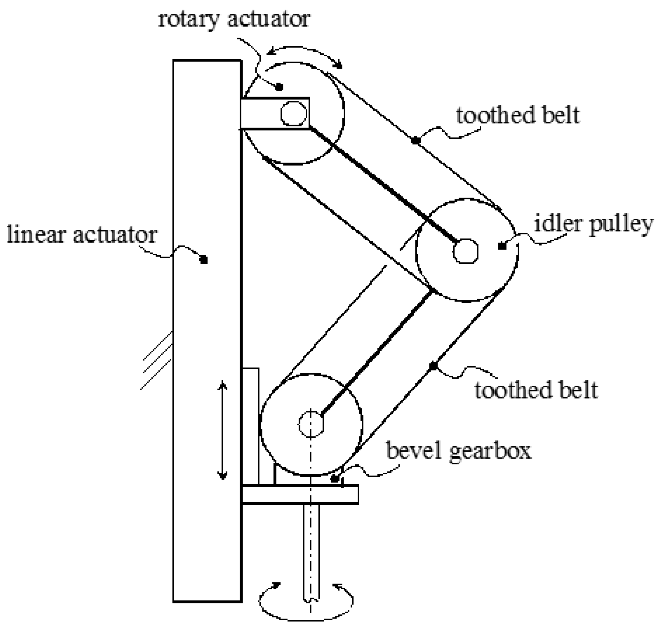
Figure 3.
The blue region indicates the values of the 2-tuple (p, ap) that satisfy inequalities (4).
Figure 3.
The blue region indicates the values of the 2-tuple (p, ap) that satisfy inequalities (4).
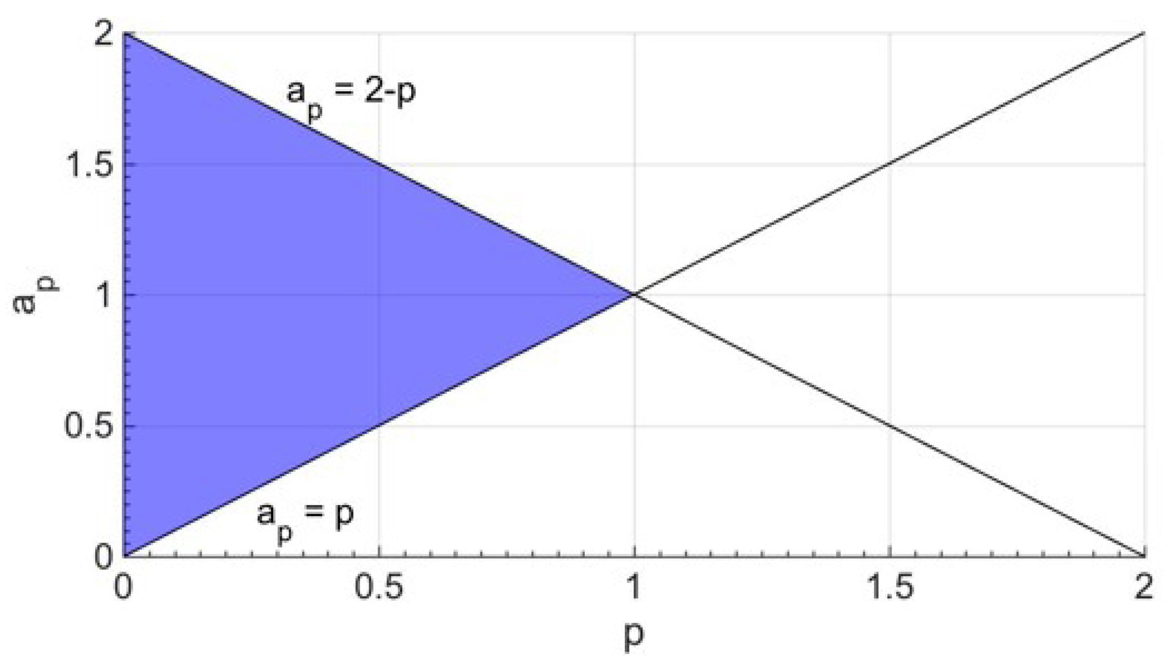
Figure 4.
The above-defined four-bar linkage, with a p value that makes it a not-Grashof four-bar, at the configurations corresponding to the extreme values of φ: (a) Δφ is swept by moving from a serial singularity (ii) to a parallel singularity, and (b) vice versa.
Figure 4.
The above-defined four-bar linkage, with a p value that makes it a not-Grashof four-bar, at the configurations corresponding to the extreme values of φ: (a) Δφ is swept by moving from a serial singularity (ii) to a parallel singularity, and (b) vice versa.

Figure 5.
The minimum, μmin (Equation (8a)), and the maximum, μmax (Equation (8b)), transmission angles as a function of p for a3 = a4 = ap = 1 (l.u.).
Figure 5.
The minimum, μmin (Equation (8a)), and the maximum, μmax (Equation (8b)), transmission angles as a function of p for a3 = a4 = ap = 1 (l.u.).
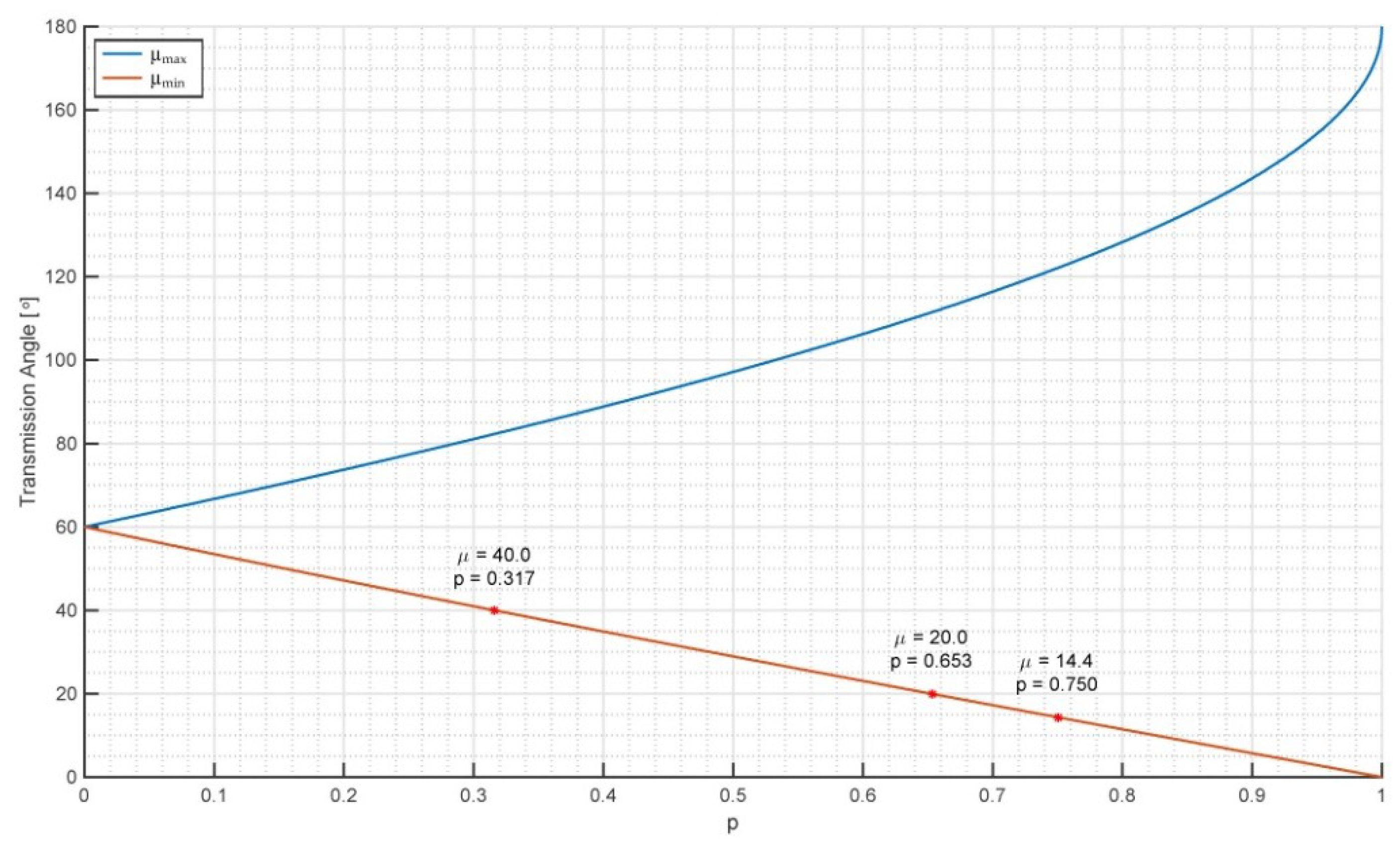
Figure 6.
Region of the xbyb plane swept during motion by the above-defined four-bar linkage with a3 = a4 = ap = 400 mm and a useful workspace with a base radius of 300 mm.
Figure 6.
Region of the xbyb plane swept during motion by the above-defined four-bar linkage with a3 = a4 = ap = 400 mm and a useful workspace with a base radius of 300 mm.

Figure 7.
The values of (a1,a2) that satisfy inequalities (6a), (6b) and a2 ≤ a1 with a0 = 800 mm and pGr = ap = 400 mm are those belonging to the blue region.
Figure 7.
The values of (a1,a2) that satisfy inequalities (6a), (6b) and a2 ≤ a1 with a0 = 800 mm and pGr = ap = 400 mm are those belonging to the blue region.
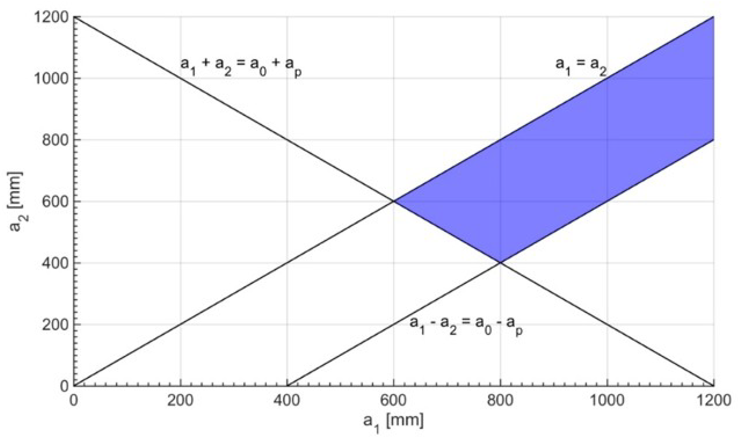
Figure 8.
Kinetostatic performance as a function of a1 and a2: (a) global conditioning index (GCI) evaluated on the useful workspace, and (b) CImin in the useful workspace.
Figure 8.
Kinetostatic performance as a function of a1 and a2: (a) global conditioning index (GCI) evaluated on the useful workspace, and (b) CImin in the useful workspace.

Figure 9.
Minimum conditioning index (CI) values at each A1 position inside the useful workspace for a1 = 950 mm and a2 = 600 mm.
Figure 9.
Minimum conditioning index (CI) values at each A1 position inside the useful workspace for a1 = 950 mm and a2 = 600 mm.
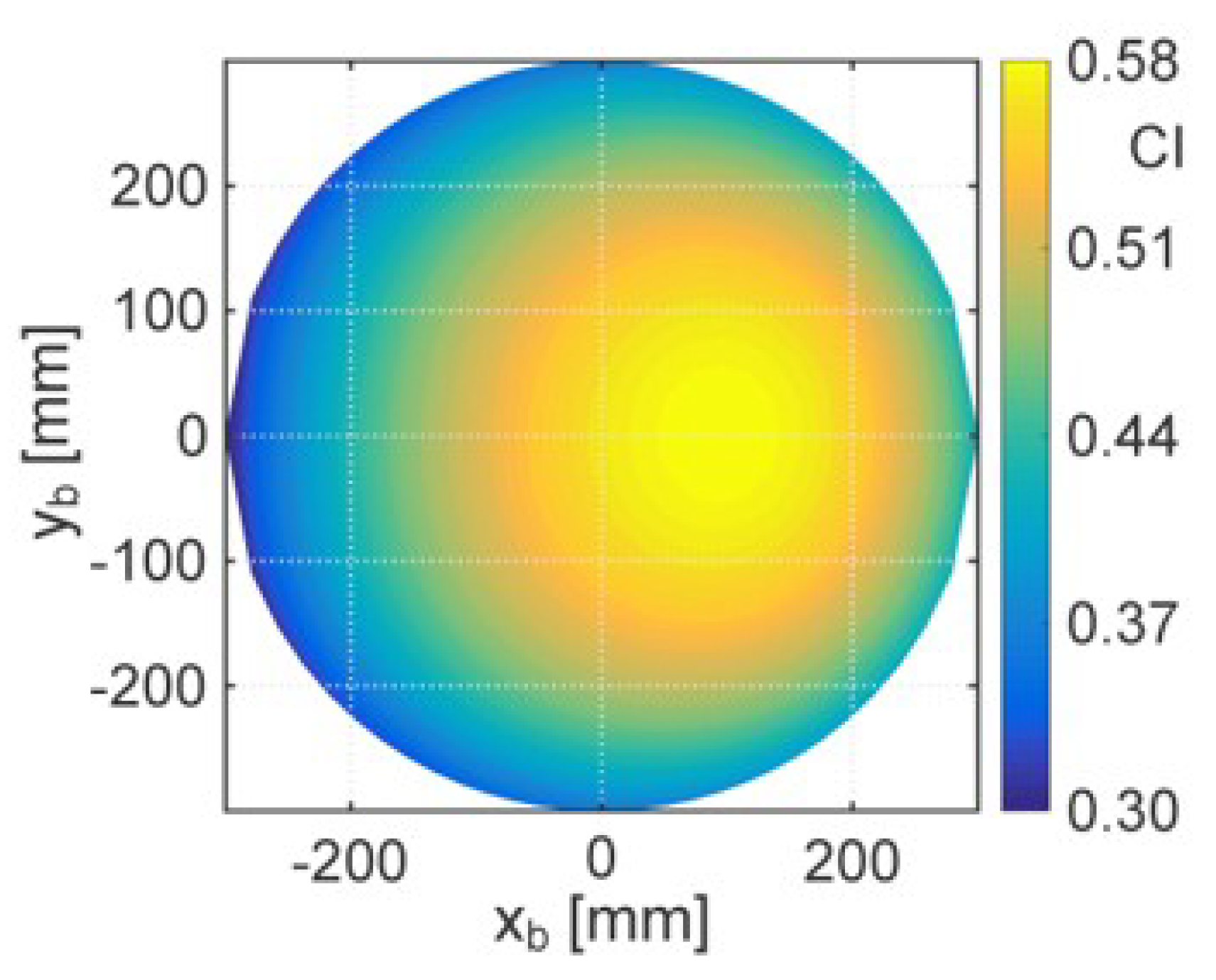
Figure 10.
Region of the xbyb plane swept by the RRC limb, with a0 = 800 mm, a1 = 950 mm, and a2 = 600 mm, when point A1 is moved on the whole circular border of the useful workspace and the limb is assembled in either of the two assembly modes the inverse position analysis (IPA) identifies.
Figure 10.
Region of the xbyb plane swept by the RRC limb, with a0 = 800 mm, a1 = 950 mm, and a2 = 600 mm, when point A1 is moved on the whole circular border of the useful workspace and the limb is assembled in either of the two assembly modes the inverse position analysis (IPA) identifies.

Figure 11.
Overall region of the xbyb plane that is swept by both the limbs.
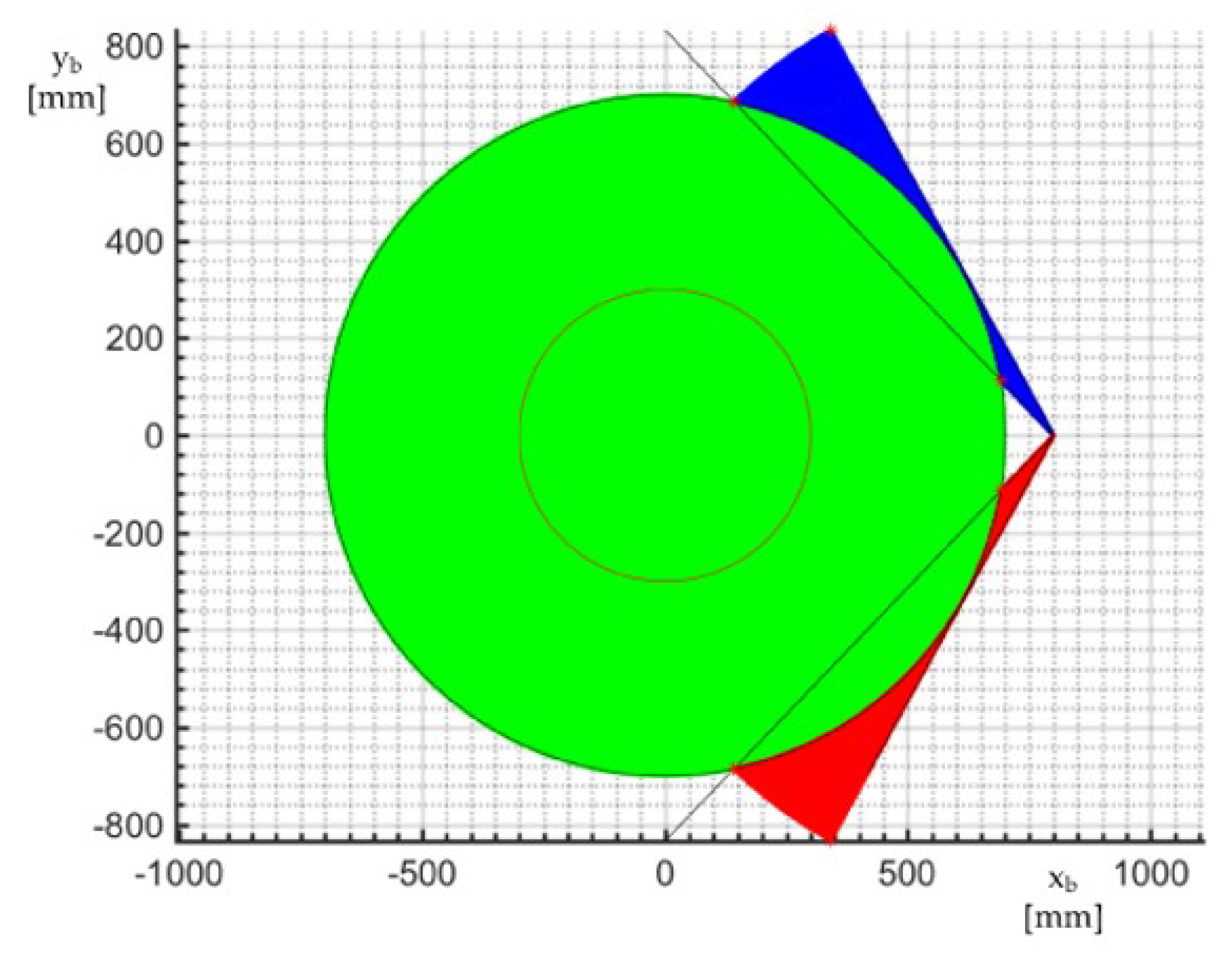
Figure 12.
CAD model: (a) 3D view, and (b) lateral view.

© 2018 by the authors. Licensee MDPI, Basel, Switzerland. This article is an open access article distributed under the terms and conditions of the Creative Commons Attribution (CC BY) license (http://creativecommons.org/licenses/by/4.0/).
Share and Cite
MDPI and ACS Style
Di Gregorio, R.; Cattai, M.; Simas, H. Performance-Based Design of the CRS-RRC Schoenflies-Motion Generator. Robotics 2018, 7, 55. https://doi.org/10.3390/robotics7030055
AMA Style
Di Gregorio R, Cattai M, Simas H. Performance-Based Design of the CRS-RRC Schoenflies-Motion Generator. Robotics. 2018; 7(3):55. https://doi.org/10.3390/robotics7030055
Chicago/Turabian StyleDi Gregorio, Raffaele, Mattia Cattai, and Henrique Simas. 2018. "Performance-Based Design of the CRS-RRC Schoenflies-Motion Generator" Robotics 7, no. 3: 55. https://doi.org/10.3390/robotics7030055
Note that from the first issue of 2016, this journal uses article numbers instead of page numbers. See further details here.