Abstract
Most snakes in nature have scales at their ventral sides. The anisotropic frictional coefficient of the ventral side of the snakes, as well as snake robots, is considered to be responsible for their serpentine kind of locomotion. However, little work has been done on snake scales so far to make any guidelines for designing snake robots. This paper presents an experimental investigation on the effects of artificial scale geometry on the motion of snake robots that move in a serpentine manner. The motion of a snake robot equipped with artificial scales with different geometries was recorded using a Kinect camera under different speeds of the actuating motors attached to the links of the robot. The results of the investigation showed that the portion of the scales along the central line of the robot did not contributed to the locomotion of the robot, rather, it is the parts of the scales along the lateral edges of the robot that contributed to the motion. It was also found that the lower frictional ratio at low slithering speeds made the snake robot motion unpredictable. The scales with ridges along the direction of the snake body gave better and more stable motion. However, to get the peg effect, the scales needed to have a very high lateral to forward friction ratio, otherwise, significant side slipping occurred, resulting in unpredictable motion.
1. Introduction
Snakes possess a unique feature of locomotion that no other creature has. Although legs and wheels give very effective and efficient motion, this creature has the unique ability to move through terrains that are almost impossible to travel through by limbs or wheels. Thus, the ability to move through almost all kinds of surfaces puts snakes in a superior position in terms of locomotion. Snakes have four basic types of locomotion: concertina, serpentine, sidewinding, and rectilinear. Among these, the serpentine locomotion is a faster and a very efficient one for normal conditions. Thus, this motion can be proven exceptionally beneficial in snake robot applications such as search and rescue [1,2], firefighting [3,4], assisting in surgery [5,6], surveillance [7,8] exploring unknown territory, and so forth.
The mechanics of serpentine locomotion were first discovered and explained by J. Gray [9] in 1946. According to Gray, the serpentine locomotion of snakes is due to the lateral friction of the scales of a snake that work as supporting pegs. After the ground breaking discovery of J. Gray, Hu et al. [10] carried out several investigations on real snakes and established the theory experimentally. Some more works on biological snakes that were not focused on the analysis or investigation of the forces applied by the snakes took place. Jayne [11,12] was more focused on the muscular activities during the different types of locomotion with extensive work on serpentine and sidewinding locomotion. Jayne provided extraordinary information regarding the optimization of the actuation method and the energy for the future developments of robots. Meanwhile Miller [13] simulated the motion dynamics of snake locomotion. Later on, Jayne and Davis [14] developed a relationship between the tunnel width and the speed, or, in other words, the movable space available and the speed of the snake using the kinematics of the concertina locomotion of snake. Marvi and his group studied the friction augmentation by the snakes in concertina locomotion [15].
The archive of information on snake robots dates back to the year 1993 when S. Hirose developed the idea of the locomotion of a snake robot [16], encouraging researchers in working consistently to improve and optimize their artificial snakes. For instance, Wang, Osborne, and Alben [17] and Jing and Alben [18] optimized locomotion on an inclined surface. Instead of real snakes, Kyriakopoulos, Migadis, and Sarrigeorgidis [19] worked on the kinematics of snake robots and provided a design and motion planning in 1999. Prautsch and Mita developed a theory for the dynamic position control [20] for snake robots. Khan et al. [21] first developed a scale based snake trying to mimic the serpentine motion. Later on, they put forward their previous work by investigating the snake robot moving with the serpentine method of locomotion [22]. Apart from that, Marvi et al. [23] presented a snake inspired robot segment based on concertina locomotion in 2011. It was capable of changing the angle of attack of its scales with the change in the slope angle while climbing uphill. They also worked on sidewinding with minimal slips for both the snake and the snake robot on sandy slopes [24]. Varesis, Diamantopoulos, and Tzes [25] conducted an experiment on robots with serpentine locomotion moving through an inclined surface [23]. However, none of the works on artificial snake scales considered the geometry of the scales to investigate the motion of the snake robots. As a continuation of the above efforts, this paper presents the effects of the scale geometry and the friction factor on the locomotion of a snake robot.
This paper is organized as follows. The experimental setup and data acquisition system are described in Section 2, while the effect of the surface properties on motion and the effect of the surface on the directional stability are presented in Section 3 and Section 4, respectively. Section 5 draws the conclusions of the paper.
2. The Experimental SETUP and Data Acquisition
A snake robot made of nine links, eight servo-motors, and a microcontroller, as shown in Figure 1, was used in this research. The microcontroller was programmed for controlling the motion of the servo-motors and propelling the snake in a serpentine motion. The snake’s scales were attached at the ventral side of the snake robot, while markers were attached on the dorsal side to keep track of the motion of the robot.
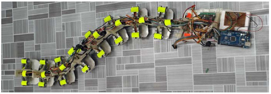
Figure 1.
The snake robot with markers on the dorsal side.
Four different types of scales were used to investigate the effect of scale geometry and the coefficient of friction on the motion of the snake robot. Photographs and the geometry of the scales are shown in Figure 2a–d. On an average, the span of the scales was 20 mm, except for the scale in Figure 2d. The scales shown in Figure 2a were fabricated from Acrylonitrile Butadiene Styrene (ABS) using a 3D printer while the scales shown in Figure 2b,c were made of ordinary plastic shells and externally threaded cylinder (Cylinder_1), splitting the cylinders into two halves. In Figure 2d, a scale made from an externally threaded cylinder with a lower friction factor than Cylinder_1 (we call it Cylinder_2) extending between the left and right edge of a link is shown.
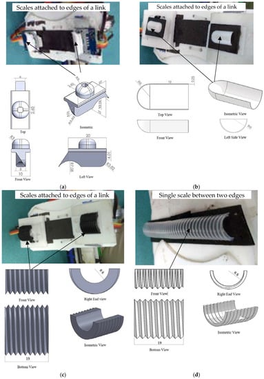
Figure 2.
The photographs of the snake scales attached to the links of the snake robot and orthographic views of the scales (a) Designed scale; (b) Unthreaded scale (half-shell); (c) Threaded scale (Cylinder_1); (d) Threaded scale (Cylinder_2).
As the goal of this research is to investigate the effect of scale geometry on the motion of snake robots, the robot was equipped with one type of scale at a time. One pair of scales were attached at the lateral edges of each link of the robot. The snake robot was run on three different floor surfaces, namely, Surface 1 (Cloth), Surface 2 (artificial lather 1), and Surface 3 (artificial leather 2). The static friction coefficients between the snake scales and the surfaces are presented in Table 1. One of the main features of the snake scales was the anisotropic friction coefficients along the tangential and normal directions. Frictional anisotropy were achieved through the design of the snake scales of the snake robot.

Table 1.
The static friction coefficients between the scales and different surfaces.
Figure 3 illustrates the robot orientation and the positions of the scales L1 through R4. Where ‘L’ denotes the left side and ‘R’ denotes the right side looking from the top of the robot. A Microsoft Kinect XBOX was attached on a frame above the plane of the motion to capture the motion and the shape of the robot during its motion. A photograph of the experimental setup is shown in Figure 4.
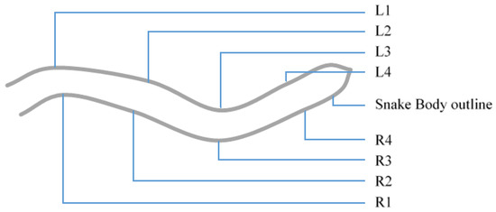
Figure 3.
The snake’s shape and scale placement (L and R stands for left and Right respectively).
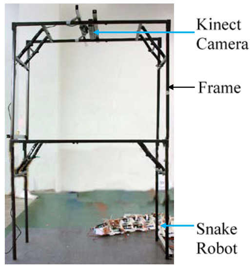
Figure 4.
The experimental setup for the snake’s motion capture.
3. The Effect of the Surface Properties on Motion
The otion data of the snake robot are presented in Table 2.
Table 2.
The motion characteristics of the snake robot with different scales on different surfaces at different motor speeds.
Table 2 compares four motion elements like the number of cycles per second (seven cycles were taken for each observation), the distance traveled by the robot per cycle, the average velocity of the robot, and the deviation from the initial axis or orientation of the robot after each cycle corresponding to three different motor speeds, namely, high speed, medium speed, and low speed. The three types of motions (high, medium, and low) of the robot were the cycle speed of the sine wave those were created by controlling the speed of the 8 actuating motors. The symbol ‘X’ in the first row of this table means no data, that is, the robot was unable to move without damaging itself on surface 1 with the designed scale as the scale got stuck in the surface. The velocity of the robot should depend on the frequency of the sine wave of the snake robot. This is evident when the velocities of the robot under three types of motion are compared under the three types of motion. The highest velocity (2.918 cm/s) was achieved in the case of the cylinder_1 on surface 1 corresponding to the high speed of the motors. This surface combination also produces the highest velocity corresponding to the medium and low speed of the motors. The angular deviation of the robot θ from its initial orientation, in the case of the high and medium speeds, are 5.638° and 8.607°, respectively, which are quite high compared to the 0.533° that happened in the case of low speed. The friction ratio for this surface combination is lower than that of the cylinder_1 on surface 2, however, the coefficient of friction along the normal direction for cylinder_1 on surface 1 is the highest (μ = 0.399). Thus, it may be concluded that the higher value of the coefficient of friction along the normal direction plays a significant role in increasing the speed of the robot.
Among the four types of scales and the three types of surfaces, the friction coefficient of surface 2 gives the maximum possible friction ratios between the tangential and normal friction coefficient (Table 1), while the threaded cylinder_1 on surface 2 gives the highest friction ratio among them all. The comparison of the robot velocities of the designed scale on surface 2 and that of cylinder_1 on surface 2 showed very similar results. The robot velocities achieved in these cases are almost half that of cylinder_1 on surface 1 for all types of motor speed. However, the angular deviations are significantly low except for the low speed of the motors. The half shell on surface 3 has the highest movement with better stability (lowest angular deviation) than others, while the smooth half shell gives the minimum distance per cycle. It is noticed that the half shell had the highest friction ratio on surface 3. The last piece of data is a very important one, this data is for the threaded cylinder_2 on surface 2 (the one with the highest friction ratio) where the scales are placed at the mid surface (centerline) of the links instead of at the edges of the links. It shows that it does not move even a centimeter, yet, the same scale on the same surface gave the best output among all other combinations. Thus, it can be concluded that snake scales need to be placed at the edges of the links for the better motion of the robot, and it is unnecessary to place the snake scales along the centerline of the links.
4. The Effect of the Surface on Directional Stability
The poses of the robot after each cycle of motion are presented in Figure 5. Each line in these figures is the connecting line between the head and tail of the robot after each cycle of actuation. Thus, these lines are presenting the change in position as well as change in the orientation with respect to the x-y axis. The initial orientation of the robot was parallel to the x axis.
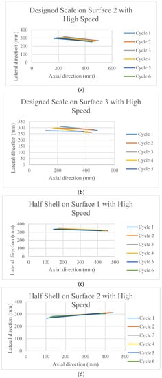
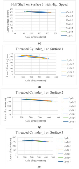
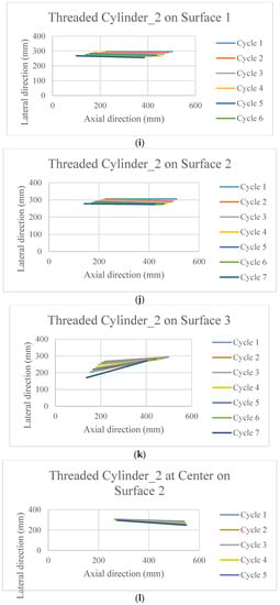
Figure 5.
The poses of the snake robot on the different surfaces at the end of each cycle of actuation.
It is observed in Figure 5a–l that the surfaces and the scales have profound effects on the directional stability and motion for the movement of the robot.
Due to practical reason it was not possible to run the robot on surface 1 using the designed scale, thus, the data is absent. However, some important phenomena can be observed from the rest of the figures. All the scales that have threads on it (other than Figure 5c–e,l) are superior in terms of stability in the motion direction, as well as the distance covered. On top of that, when they move on the surface 1 (cloth) (Figure 5f,i) which has an anisotropic friction property within itself, cover higher distance. On the other hand, the half shell (Figure 5c–e) did not have much of a promising outcome in terms of the directional stability and velocity. On surface 2, the motion direction is better maintained than that on surface 3.
All the orientations of the snake robot after the last cycle of actuation found in Figure 5a–l are presented in Figure 6. A very important finding that is observed in the last set of data in Figure 5l is shown circled in red in Figure 6. This is the situation when the scales were placed in the middle of the snake body leaving the edges of the link free and floating. There is no significant movement as well as no control of direction in this case. In fact, the robot moved in the backward direction instead of moving forward, however, the same threaded cylinder 2 with the scale at the outer edges of the links gave better robot motion.
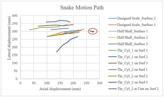
Figure 6.
The comparison of the motion paths of the snake head on different surfaces.
5. Conclusions
This work makes an effort to discover the relationship between the different variables of the snake scales, like friction ratio, scale geometry, and the span of the scales beneath a snake robot that undergoes serpentine motion. The comparison of the motion shows that scales with a higher friction ratio set at the outer edge of the snake robot helps to generate better and more stable motion. On the other hand, scales only at the center of the belly, irrespective of the friction ratio, does not help the robot to generate any good motion or any forward motion at all. Scales have a ridge like texture on it along the direction of the snake body, which, when placed at the outer edge of the belly, helps generate stable and faster motion. It is predictable from the above experiments that the higher friction ratio will help achieve higher and better motion. Motions with the actuating motors at lower cycle speeds with a scale-surface pair having a lower friction ratio are very unpredictable in nature.
Author Contributions
Writing –Original Draft Preparation, Naim Md. Lutful Huq; Supervision, Funding Acquisition & Project administration, Md. Raisuddin Khan and Amir Akramin Shafie; Software, Md. Masum Billah; Methodology, Syed Masrur Ahmmad.
Funding
This research was funded by Ministry of Higher Education (MOHE) grant number FRGS13-072-0313.
Acknowledgments
The authors profoundly acknowledge the Ministry of Higher Education (MOE), Malaysia for funding this research through the Fundamental Research Grant Scheme (FRGS).
Conflicts of Interest
The authors declare no conflicts of interest.
References
- Casper, J.; Murphy, R.R. Human-robot interactions during the robot-assisted urban search and rescue response at the world trade center. IEEE Trans. Syst. Man Cybern. Part B Cybern. 2003, 33, 367–385. [Google Scholar] [CrossRef] [PubMed]
- Wolf, A.; Brown, H.B.; Casciola, R.; Costa, A.; Schwerin, M.; Shamas, E.; Choset, H. A mobile hyper redundant mechanism for search and rescue tasks. In Proceedings of the 2003 IEEE/RSJ International Conference on Intelligent Robots and Systems, Las Vegas, NV, USA, 27–31 October 2003; Volume 3, pp. 2889–2895. [Google Scholar]
- Liljeback, P.; Stavdahl, O.; Beitnes, A. SnakeFighter-development of a water hydraulic firefighting snake robot. In Proceedings of the 9th International Conference on Control, Automation, Robotics and Vision, ICARCV’06, Singapore, 5–8 December 2006; pp. 1–6. [Google Scholar]
- Cai, L.; Zhang, R. Design and Research of Intelligent Fire-Fighting Robot. Adv. Mater. Res. 2013, 823, 358–362. [Google Scholar] [CrossRef]
- Ho, C.; Chen, M.; Lien, C. Machine Vision-Based Intelligent Fire Fighting Robot. Key Eng. Mater. 2010, 450, 312–315. [Google Scholar] [CrossRef]
- Degani, A.; Choset, H.; Wolf, A.; Zenati, M.A. Highly articulated robotic probe for minimally invasive surgery. In Proceedings of the 2006 IEEE International Conference on Robotics and Automation, ICRA 2006, Orlando, FL, USA, 15–19 May 2006; pp. 4167–4172. [Google Scholar]
- Tully, S.; Kantor, G.; Zenati, M.A.; Choset, H. Shape estimation for image-guided surgery with a highly articulated snake robot. In Proceedings of the 2011 IEEE/RSJ International Conference on Intelligent Robots and Systems (IROS), San Francisco, CA, USA, 25–30 September 2011; pp. 1353–1358. [Google Scholar]
- Granosik, G.; Hansen, M.G.; Borenstein, J. The OmniTread serpentine robot for industrial inspection and surveillance. Ind. Robot 2005, 32, 139–148. [Google Scholar] [CrossRef]
- Granosik, G.; Borenstein, J.; Hansen, M.G. Serpentine robots for industrial inspection and surveillance. In Industrial Robotics: Programming, Simulation and Applications; I-Tech Publ.: London, UK, 2007; pp. 633–662. [Google Scholar]
- Gray, J. The mechanism of locomotion in snakes. J. Exp. Biol. 1946, 23, 101–120. [Google Scholar] [PubMed]
- Hu, D.L.; Nirody, J.; Scott, T.; Shelley, M.J. The mechanics of slithering locomotion. Proc. Natl. Acad. Sci. USA 2009, 106, 10081–10085. [Google Scholar] [CrossRef] [PubMed]
- Jayne, B.C. Muscular mechanisms of snake locomotion: An electromyographic study of the sidewinding and concertina modes of Crotaluscerastes, Nerodiafasciata and Elapheobsoleta. J. Exp. Biol. 1988, 140, 1–33. [Google Scholar] [PubMed]
- Jayne, B.C. Muscular mechanisms of snake locomotion: An electromyographic study of lateral undulation of the Florida banded water snake (Nerodiafasciata) and the yellow rat snake (Elapheobsoleta). J. Morphol. 1988, 197, 159–181. [Google Scholar] [CrossRef] [PubMed]
- Miller, G.S. The motion dynamics of snakes and worms. In Proceedings of the ACM Siggraph Computer Graphics and Interactive Techniques, Atlanta, GA, USA, 1–5 August 1988; Volume 22, pp. 169–173. [Google Scholar]
- Jayne, B.C.; Davis, J.D. Kinematics and performance capacity for the concertina locomotion of a snake (Coluber constrictor). J. Exp. Biol. 1991, 156, 539–556. [Google Scholar]
- Marvi, H.; Hu, D.L. Friction enhancement in concertina locomotion of snakes. J. R. Soc. Interface 2012, 9, 3067–3080. [Google Scholar] [CrossRef] [PubMed]
- Hirose, S. Biologically Inspired Robots; Oxford University Press: Oxford, UK, 1993. [Google Scholar]
- Wang, X.; Osborne, M.T.; Alben, S. Optimizing snake locomotion on an inclined plane. Phys. Rev. E 2014, 89. [Google Scholar] [CrossRef] [PubMed]
- Jing, F.; Alben, S. Optimization of two-and three-link snakelike locomotion. Phys. Rev. E 2013, 87. [Google Scholar] [CrossRef] [PubMed]
- Kyriakopoulos, K.J.; Migadis, G.; Sarrigeorgidis, K. The NTUA snake: Design, planar kinematics, and motion planning. J. Robot. Syst. 1999, 16, 37–72. [Google Scholar] [CrossRef]
- Prautsch, P.; Mita, T. Control and analysis of the gait of snake robots. In Proceedings of the 1999 IEEE International Conference on Control Applications, Kohala Coast, HI, USA, 22–27 August 1999; Volume 1, pp. 502–507. [Google Scholar]
- Khan, R.; Watanabe, M.; Shafie, A.A. Kinematics model of snake robot considering snake scale. Am. J. Appl. Sci. 2010, 7, 669. [Google Scholar] [CrossRef]
- Marvi, H.; Gong, C.; Gravish, N.; Astley, H.; Travers, M.; Hatton, R.L.; Mendelson, J.R., III; Choset, H.; Hu, D.L.; Goldman, D.I. Sidewinding with minimal slip: Snake and robot ascent of sandy slopes. Science 2014, 346, 224–229. [Google Scholar] [CrossRef] [PubMed]
- Khan, R.; Billah, M.; Huq, N.; Helmi, M.; Ahmmed, S. Investigation on Data Extraction Trends for Snake Robot. Procedia Comput. Sci. 2014, 42, 145–152. [Google Scholar] [CrossRef][Green Version]
- Varesis, O.; Diamantopoulos, C.; Tzes, A. Experimental studies of serpentine motion control of snake robots at inclined planes. In Proceedings of the 2016 24th Mediterranean Conference on Control and Automation (MED), Athens, Greece, 21–24 June 2016; pp. 737–742. [Google Scholar]


© 2018 by the authors. Licensee MDPI, Basel, Switzerland. This article is an open access article distributed under the terms and conditions of the Creative Commons Attribution (CC BY) license (http://creativecommons.org/licenses/by/4.0/).