Article

High Performance Motion-Planner Architecture for Hardware-In-the-Loop System Based on Position-Based-Admittance-Control

by
Francesco La Mura
1,*,
Giovanni Todeschini
2 and
Hermes Giberti
3,*
1
Department of Mechanical Engineering, Politecnico di Milano, 20156 Milano, Italy
2
Todeschini Mario Srl, Via Carlo Porta, 38, 23861 Cesana Brianza LC, Italy
3
Dipartimento di Ingegneria Industriale e dell’Informazione, Università degli Studi di Pavia, Via A. Ferrata 5, 27100 Pavia, Italy
*
Authors to whom correspondence should be addressed.
Robotics 2018, 7(1), 8; https://doi.org/10.3390/robotics7010008
Submission received: 8 November 2017 / Revised: 16 January 2018 / Accepted: 23 January 2018 / Published: 1 February 2018

Abstract

:
This article focuses on a Hardware-In-the-Loop application developed from the advanced energy field project LIFES50+. The aim is to replicate, inside a wind gallery test facility, the combined effect of aerodynamic and hydrodynamic loads on a floating wind turbine model for offshore energy production, using a force controlled robotic device, emulating floating substructure’s behaviour. In addition to well known real-time Hardware-In-the-Loop (HIL) issues, the particular application presented has stringent safety requirements of the HIL equipment and difficult to predict operating conditions, so that extra computational efforts have to be spent running specific safety algorithms and achieving desired performance. To meet project requirements, a high performance software architecture based on Position-Based-Admittance-Control (PBAC) is presented, combining low level motion interpolation techniques, efficient motion planning, based on buffer management and Time-base control, and advanced high level safety algorithms, implemented in a rapid real-time control architecture.

1. Introduction

Hardware-In-the-Loop (HIL) is becoming a fundamental tool for both hardware and software components development [1]. It combines many advantages of both physical and virtual prototyping, allowing rapid, accurate and cheap development of increasingly complex integrated systems. The basic idea of this technique is to test a single real component or subsystem, in conjunction with virtual or emulated parts of the complete system or environment. This general concept has been performed in many different ways: sometimes actual hardware components are tested through actuated interfaces emulating their interaction with other parts of the system or environment; other times control hardware and logics are tested and optimized simulating the controlled part of the system and managing inputs/outputs coming from actual or emulated sensors.
Examples of successful HIL use are commonplace in many different fields and applications, ranging from flight simulation, through to military/space applications [2] such as missiles guidance control [3], complex battlefield simulation involving a hostile environment, soldiers and vehicles [4]. Automotive applications have also played a fundamental role, inter alia: single subsystems to test active/passive suspensions, engines [5], power trains, tires, brakes with Anti-lock-Braking-System (ABS) or Electronic-Stability-Program (ESP) control systems, to Driver-In-the-Loop (DIL) virtual simulations [6], immersing real cockpit or even complete vehicles in virtual environments. The advantages of hardware/software in the loop solutions are many [1], among which are:
  • Cost effectiveness, in fact it allows one to reduce the number of costly in-field tests and use these only for advanced development stages of the system.
  • Repeatability and variety of test conditions, difficult to reproduce in an actual environment.
  • Safety and accuracy, due to the possibility of integrating hard to predict and simulate parts of the system, like human beings, complex actuators, sensors and the like. Moreover, potentially dangerous conditions and system failures can be simulated in a safe way.
  • Concurrent systems engineering, since HIL offers development teams the possibility of working on their hardware or control algorithms without losing sight of integration issues, allowing testing at different levels of completion and coordination of the whole system.
The Loop term in “Hardware In the Loop” definition is considered to be correctly used [5] when information and influence exchange occurs bidirectionally between real and simulated subsystems. Bidirectional communication allows one to test complex interaction issues but this is possible only with a high computational effort and modern solutions to achieve adequate Real-Time performance. Due to limitation of sampling frequency, possible communication issues and delays, performance achievable and overall HIL reliability depend greatly on bandwidth features for both real and simulated part of the system. Moreover, even when simulation time steps are carefully chosen, it is necessary to verify calculation accuracy and simulated/emulated system perception/transparency to validate any measurement made on the hardware components in loop. This aspect becomes even more critical when complex dynamic systems are simulated and the effects of these simulations are applied on a real system by means of a complex actuated interface with a nonlinear dynamic behaviour [7]. In these cases not only must the performance of the system be taken into account but also the safety and integrity aspects of the HIL components. In particular, an extra computational effort has to be considered to predict the operating conditions and execute specific safety algorithms.
This paper deals with this very challenging category of HIL developed for an advanced renewable energy field H2020 project named LIFES50+. The focus of the paper is to show the effective and high performance software architecture developed to reach the dynamic requirements. The control strategy used is based on Position-Based-Admittance-Control (PBAC) and combines a low level motion interpolation techniques for efficient motion planning, based on buffer management and Time-base control, with advanced high level of safety algorithms, set in a rapid real-time control architecture. The latter has been implemented and tested on a real system used as a test bench for the application set out hereunder.

2. The HIL System

LIFES50+ is an H2020 EU project [8], which is aimed at testing cost effective technology for floating substructures for 10 MW offshore wind turbines, at water depths greater than 50 m. The objective is optimizing and qualifying, to a Technology-Readiness-Level (TRL) of 5, two innovative substructures designed for 10 MW wind turbines. One of the most important factors to take into consideration for this particular application, is the combination of the aerodynamic loads, caused by the wind turbine, with the hydrodynamic ones, caused by the physical interaction between the turbine, the floating platform and the sea. This complex combination of effects could be studied with CFD software, however model validation through an experimental campaign is fundamental [9,10]. The wind turbine and the floating substructure involved in this application are both too expensive to be tested through full scale prototypes. Moreover, the floater is currently under development and different architectures are still to be taken into account.
In this framework, the HIL system has been developed with the objective of recreating the sea effects on a scaled wind turbine operating in a wind tunnel [11]. In particular, a scaled model of the 10 MW DTU wind turbine [12] is installed in the Politecnico di Milano wind tunnel. This model provides all the required aerodynamic/aero-elastic effects. The floater dynamic behaviour is simulated by means of an HIL system and a mathematical model of the floating substructures, coupled with the sea environment and its loads, and tested in closed loop with all the loads generated on the base of the wind turbine, measured by a 6 axis force/torque sensor. Sea conditions are obtained from ocean basin acquisitions, made at Norwegian Marine Technology Research Institute (MARINTEK), whilst the wind loads are directly generated by the wind tunnel. Since the combination of the floating substructure and the sea environment can be fully described by means of a 6 Degrees-Of-Freedom (DOF) model, a 6 DOF fully parallel robot has been designed for this purpose [13]. The goal of the robot, named Hexafloat, is to emulate the dynamic behaviour of the floating substructure, making it possible to simulate the hydrodynamic and aerodynamic effect interaction inside the wind tunnel environment.
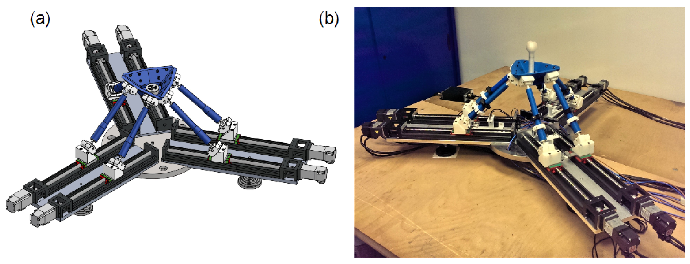
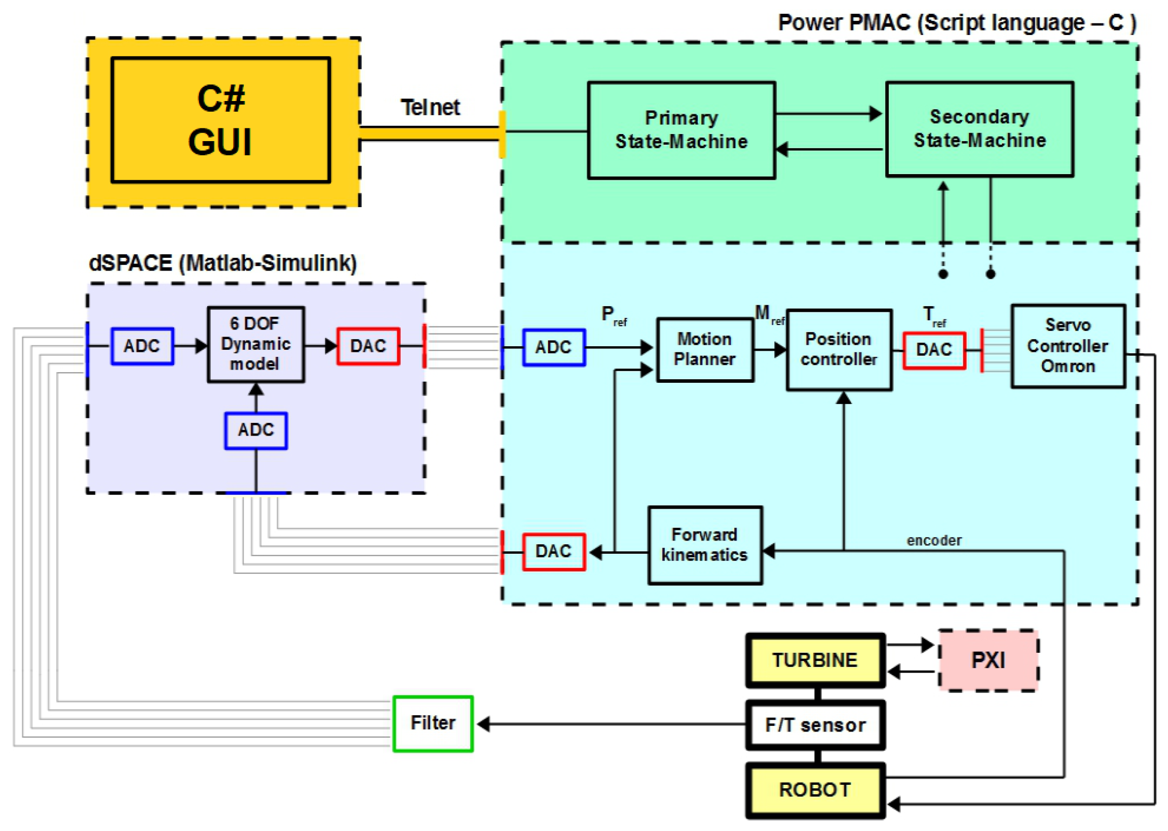
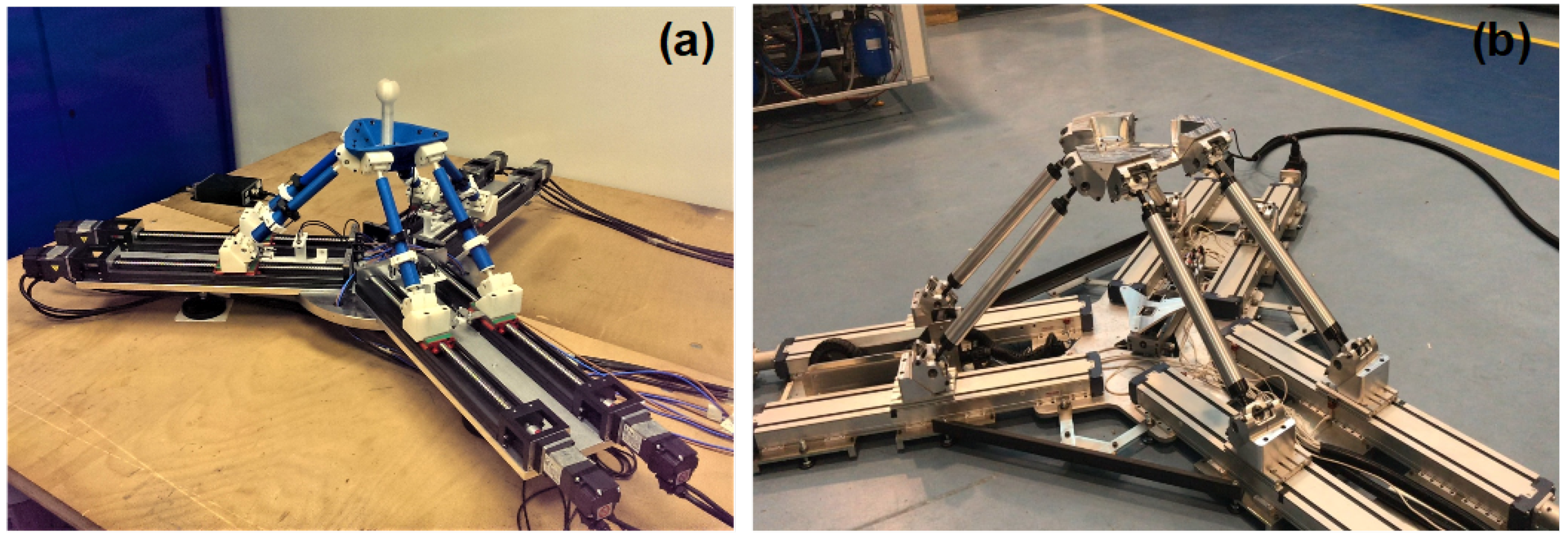
To meet project requirements, two robots have been designed and realized. The first is permanently fixed on the wind tunnel floor for the HIL tests planned for the LIFES50+ experimental activities [14]. The second robot has been designed on a 1:3 scale with the same controller, electrical architecture and communication infrastructure in order to be able to develop, verify and optimize the control and safety algorithms without keeping the wind tunnel occupied. The robot design and development has been effected using modern project methodologies among which are genetic algorithm based kinematic synthesis [15,16], MSC Adams-Simulink co-simulation environment and FEM analysis [17]. The final result is a fully parallel six DOF robot, based on the Prismatic-Universal-Spherical (PUS) or (PRRS) joints configuration, actuated by six drive brushless motors through ball screw–slider connections. A six axis force/torque sensor is installed between the turbine and robot end-effector. The Robot is completely below the scaled wind turbine in order to reduce its influence on air flow quality. The high level control software and tools together with position and velocity servo loops, have been developed on a Power PMAC motion controller, property of Omron Delta Tau, while the torque/current loop and phase commutation are controlled by 6 Mitsubishi servo controllers. Dynamic model real time integration will be performed by a special dSPACE controller, while turbine management will be handled by a completely independent PXI controller made by National Instruments NI. Figure 1 shows a simplified scheme of the HIL setup. Except for essential scale factors, control loops calibration and electrical components size, the two robots share the same software and the same control hardware architecture. Figure 2a shows the rendering of the scaled machine while, Figure 2b shows the actual scaled robot.

3. Control Architecture

For the particular application described in this article, the fundamental requirements to be met are: Firstly, the robot must receive all the external loads coming from the wind turbine and perform like a floating substructure immersed in the sea environment. Secondly, the software must guarantee HIL equipment safety and performance under all test conditions. In particular, special attention needs to be given to motion smoothness in terms of fluidity and acceleration limits in accordance with HIL safety requirements. Unexpected velocity variations or excessive accelerations imposed by the robot on high inertia flexible components fixed on the end-effector, could cause unwanted vibrations, invalidating the test measurements and potentially jeopardizing safety. Many important topics are related to the second point presented, such as trajectory planning and motion blending in the presence of unpredictable reference generation and force input, safe limitation of robot’s workspace and robot actual pose estimation starting from nonlinear forward kinematics equations, typical of Parallel Kinematics-Machines (PKMs). All these topics are even more highlighted by real-time computation requirements. These issues, together with the first fundamental requirement presented, need the combination of a fast, simple, real time feasible and accurate force control logic, combined with an efficient Motion-Planner architecture. While the Motion-Planner constitutes the core of the architecture presented, the force control represents the fundamental principle on which the HIL test is based. The kind of force control implemented falls under the Admittance control definition. For this project, tracking performances and overall delay are crucial topics for a correct closure of the HIL loop and a proper use of the resulting measurements. To reduce overall complexity and obtain larger bandwidth combined with high tracking performances, a Position-Based-Admittance-Control (PBAC) was designed. This force control is based on a low level position controller nested within a force feedback loop that, through a proper dynamic model, gives the inner loop its positional references. The aim is to hide and replace the real dynamics of the robot with the one modelled. Successful use of this force control algorithm can be found in [2,18]. Without the necessity of a dynamic model of the robot, the resulting control scheme is simple and usable in a large number of position controllers, usually provided by commercial robots or motion controller manufacturers. On the other hand, the complexity of the control is moved from an higher to a lower level, since the desired result of hand effector dynamics is achievable only if the position controller has very good performances in terms of delay, bandwidth compatibility and tracking error.
Of course, the objective of a perfect transparency, with respect to modelled dynamics, is not achievable [19]: this would mean obtaining unitary gain/zero phase lag transfer function of the controlled machine with respect to model output, and that is by definition impossible to achieve due to intrinsic control delay and the own dynamics of the robot. A more feasible objective is to design a control whose performances, combined with robot dynamics, guarantees the desired performance within a predefined frequency bandwidth.
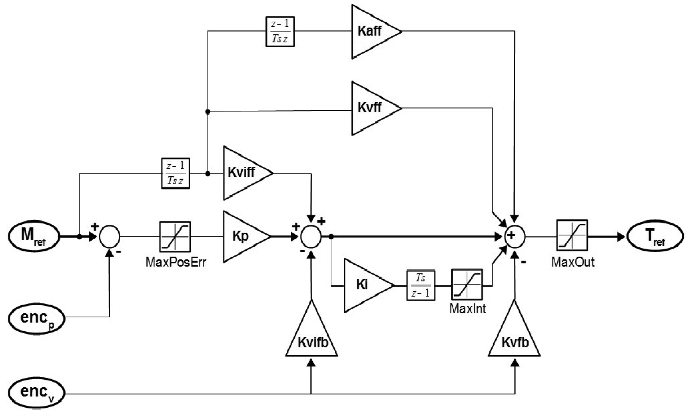
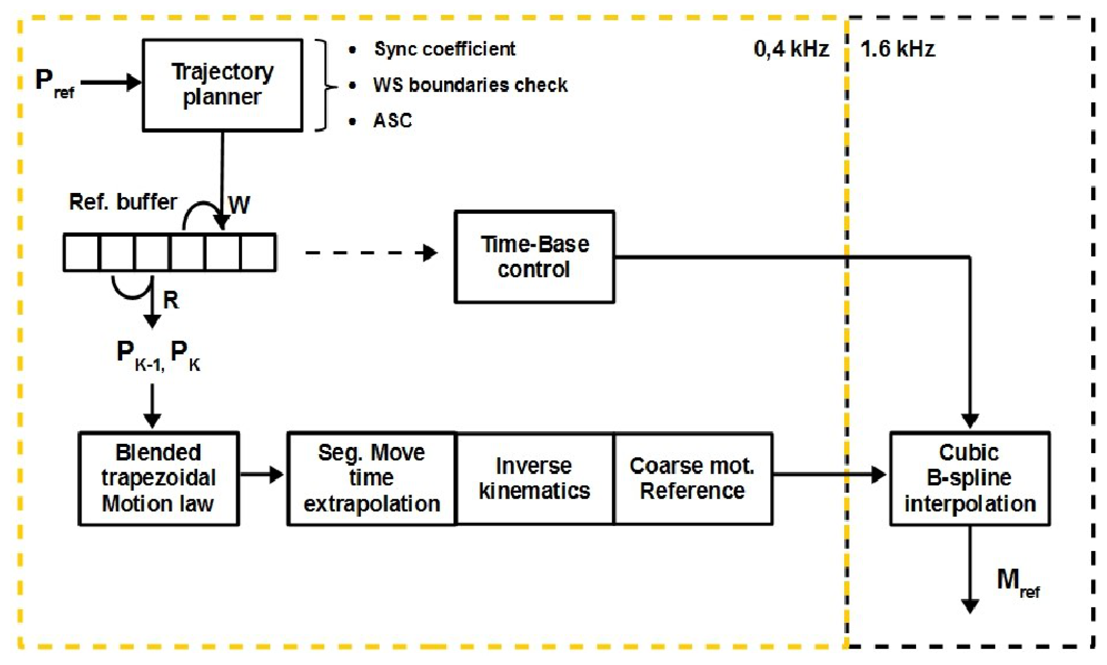
In Figure 3, the PBAC algorithm scheme is presented. The position and velocity control loops are included in the Position Controller block, and shown in more details in Figure 4. This PID architecture features position and velocity loops nested, with feedforward contributions on the velocity, acceleration and friction and anti wind-up architecture. Together with the servo control effected by Mitsubishi amplifiers, this constitutes the bottom part of the control, in the actuator workspace. As described before, the digital realization of the six DOF dynamic model accepts forces/torques input measures and gives a position reference for the Tool-Center-Point (TCP) as output; this, instead, represents the top level of the algorithm, being the TCP workspace. The connection between these two levels is effected by the textitMotion Planner, described in more detail in Figure 5. This constitutes the core of the software architecture, which meets performance and safety requirements and deal with RT bandwidth issues.

Real Time Pose Estimation

To support safety algorithms and give an important feedback to other HIL controllers, an additional routine calculates the actual pose of the robot. As is common in PKMs, the forward kinematics equations, necessary to transform six motors positions into a six components global pose for the TCP, are extremely nonlinear. Therefore, a numerical method is implemented. Since it is necessary to have real time estimation of the robot position and orientation, a fast and stable algorithm is necessary. The one chosen is based on Jacobian-Free-Monotonic-Descent-factor (JFMD) [20]. This algorithm is a modified version of the well known Newton-Raphson method, whose stability is unfortunately greatly dependent on the accuracy of the initial approximation of the solution vector: it features a descent factor that prevents divergence and guarantee more rapid convergence, even for initial guesses far from the actual robot pose. This modification is widely known as Modified-Global-Newton-Raphson (MGNR). JFMD adds to MGNR method the numerical estimation of the Jacobian matrix through very small perturbations and first order approximation of partial derivatives (for this reason called “Jacobian free” in the sense of “analytical Jacobian free”). After the first estimate has been completed, every new iterative search of the actual pose uses the last estimated pose as initial guess, decreasing ever more the calculation time. Furthermore, the algorithm has been written in C language obtaining considerable computation speed. Tests performed have shown 50 us calculation time, suitable for pose estimation at our control frequency of 1.6 kHz.

4. Motion Planner

The positioning capabilities of the machine depends on the transparency concept. In order to make the robot able to reproduce with high accuracy the output of the dynamic model, a fast and efficient motion planning algorithm is required. Besides realizing precise positioning with minimum delay, this group of cooperating algorithms have to satisfy all the safety and smoothness requirements, for every force input condition. Besides the particular HIL application proposed, the design of the Motion Planner, and its nesting inside the fast and simple PBAC force control logic, constitutes the principal novel contribution of this work. All the implemented features inside Motion Planner are organized into three main logic levels: high level algorithms, dealing with motion reference analysis and safety procedures eventually modifying it, medium level software, dealing with references buffering and time-base control, and low level algorithms, managing workspace to joint space reference transformation at high servo frequency.

4.1. High Level Algorithms

The first stage represented in Figure 5 is the Trajectory Planner. In this block are included all the safety algorithms that act on the actual reference: actual force/torque signals are sampled and the dynamic model implemented on dSPACE controller is integrated each time step, obtaining a new reference pose for the robot. Power PMAC motion controller receives this reference by means of analog signals. The new reference pose is managed by the Trajectory Planner, which eventually modifies it to respect the imposed limits about maximum TCP acceleration and robot workspace. The main parts of the safety algorithms are described in the next subsections.

4.1.1. Synchronization Coefficient

This coefficient allows to filter the reference with a settable ramp when at moving start, there is a misalignment between robot pose and trajectory starting point. This safety is required, since the dynamic model computations are performed by an external controller, and, even if aware of actual robot pose thanks to forward kinematics, it is better to perform a smooth moving start and prevent any human or numeral mistake. Once the ramp coefficient reaches the unitary value, this part of the control becomes completely transparent.

4.1.2. Workspace Boundaries Check

Since the robot workspace is limited, a safety algorithm is necessary to prevent dangerous poses to be commanded by the dynamic model and avoid abrupt stops, caused by a simple saturation arranged in TCP domain [21]. Starting from spherical coordinate system centred on TCP and using a numerical approach based on discretization, the workspace boundary calculation has been performed. Each point on the surface has been found moving on a radius and looking for constraint violations, in particular kinematic limits, passive and active joints range of motion and static multiplication of external loads. The resulting discretized surface has been approximately calculated by means of a modified ellipsoid, in order to obtain a conservative analytical form of the workspace, more easily usable in a safety algorithm. This analytical formulation is used by a safety algorithm to set a soft and hard limit surface. Safety control, whose specific functioning is not the subject of this article, looks for buffered poses outside the soft limit: briefly, if a future exit is detected, the trajectory is deflected by means of two equivalent dynamic systems virtually connected to the TCP, operating on tangential and normal directions calculated on the basis of exit points found on the surface and updated in each loop. The final result of the control is the safe and smooth deflection of the trajectory and consequent return of the TCP inside the workspace limits and the following return back to home position for moving restart. If the commanded pose is within the limits, this control does not have any additional influence in terms of delay and tracking error with respect to buffer performance.

4.1.3. Acceleration Saturation Control (ASC)

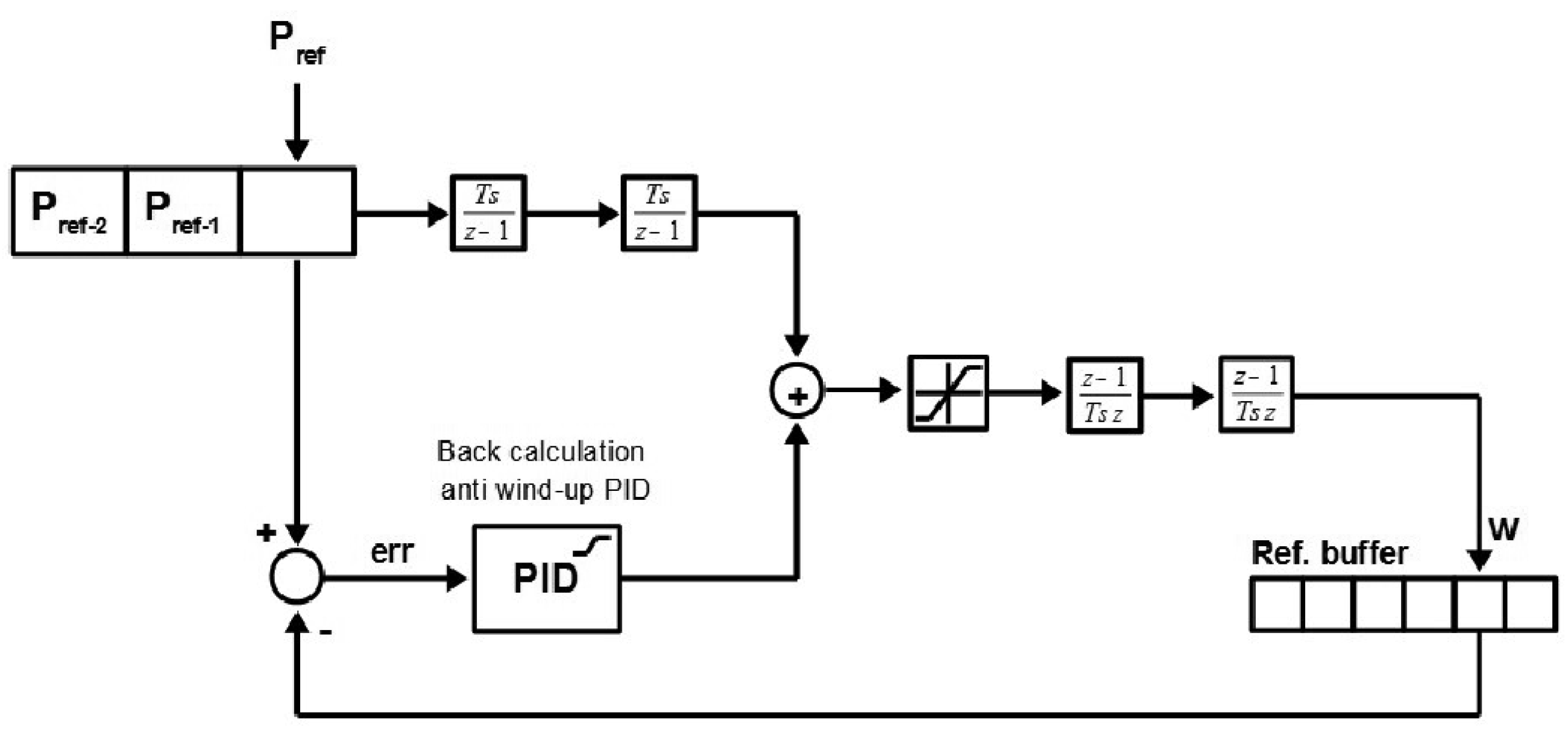
To ensure the respect of acceleration limits on the TCP, due to flexible/high inertia equipment mounted on the robot, an additional controller uses the buffered poses to compute desired acceleration; if the limits are exceeded, the acceleration is saturated and the future pose recalculated. Acceleration limits are set independently on every degree of freedom, accordingly to wind turbine inertial features. The controller features a position feedback loop with PID regulator, that restores the alignment with the reference when a residual acceleration with respect to saturation limits is available. To overcome wind-up issues typical of controllers with saturated output, a back calculation anti wind-up architecture is implemented inside the PID block in Figure 6. If the commanded acceleration is within the limits, this control does not have any additional influence in terms of delay and tracking error as regards buffer performances. Instead, it permits one to deal with unexpected numeric issues such as spikes, step signals due to procedural mistakes and signals drop due to communication problems. Controller architecture is reported in Figure 6.

4.2. Medium Level Algorithms

The middle level of the Motion Planner, which constitutes the core feature of all the architecture, is occupied by the buffer architecture and management. Every buffer slot contains a six components pose for a maximum of six slots. Once the reference pose has been processed by the trajectory planner, it is saved in the position represented by Write Index (W). This index is updated by the controller at a fixed frequency, feasible according to overall control calculation time, using a timing routine. At the same time, the motion program that uses the buffered poses, extracts the actual reference to be processed by lower level control, using a Read Index (R). This index is updated in the same direction of W, synchronously with every new move start. Using buffered poses inherently means introducing delay: every pose buffered and not executed yet, represents a move time equivalent delay. At the same time, a good buffer management ensures to have always at least one new reference available at optimum blending time, giving the opportunity to calculate high quality smooth trajectories, even for our case in which future external loads and therefore future reference poses are hardly predictable. Buffer management is based on the distance between W and R. Time-base control operates starting from the actual indexes distance and modifying the numerical value of the time constant representing the time elapsed in a single servo cycle, used inside the lowest level interpolation process, such that it can potentially no longer represents the true physical time. Each step modification of the time-base have a settable fixed amplitude, actually of 1 % with respect to servo period (6.25 us step modification starting from 0.625 ms). Time-base control is designed to be very gentle when one or few steps of modification are enough to restore default index distance in few servo cycles, and becomes more and more aggressive when subsequent modifications do not give the desired effect, both for indexes distance worsening with respect to previous condition and too long stationary condition outside default.
The purpose of this design is to always have at least one reference point ahead and at the same time working without too much delay. This allows one to remain as long as possible in the minimum delay default state, and to use the least distortion to restore the normal condition when necessary. Note that the servo-loop dynamics is not effected because the time lag between the servo cycles remains constant. By modifying such time constant one can either slow down or speed up a single move sub-section within the low level servo loop. Obviously, the overall delay depends on the single move time and a fast and optimized software allows one to reduce the time lag depending on every single movement.
The designed software has an efficient priority management and uses the pauses caused by the timing routines in order to execute other functional tasks including those which are not discussed in this paper. Therefore, even though the buffer architecture introduces an inevitable delay, this is useful in executing all the other tasks. The end effect is that the performance and the overall delay remain constant thus producing a more deterministic behaviour of the entire system.

4.3. Low Level Algorithms

At the lowest level of the Motion Planner the transformation from TCP workspace to the actuators occurs. The last pose commanded and the last one read by the buffer are connected by means of a triangular velocity motion curve with fixed duration. Subsequent velocity profiles are joined merging the deceleration section of the previous motion curve with the acceleration of the one following. Thus, the new target pose is required at the beginning of the deceleration phase for every movement.
“Routines timing” and “time base control” make this possible always without jerky movements in the event that the new pose is not yet available. In fact, without buffer management, this will occur regularly because a fixed CPU clock resolution influences every timing routine and causes a slight overestimation of the waiting time of the control threads. The resulting motion curve is continuous and is sampled by using intermediate points. The time lag between these points is fixed and equal to the so called Segmentation move time. Through the inverse kinematic solution, every sample is transformed in the joint space.
Finally, to obtain the high frequency position setpoints for servo actuators, a second interpolation stage, through a cubic b-spline method, is used. At this level, the time base control modifies the constant time for the high frequency interpolation and introduces a slight velocity alteration if necessary.

5. Experimental Setup and Results

In Figure 7, the complete HIL setup control scheme is shown. The architecture described has been tested and optimized on the 1:3 scaled robot using an ATI mini45 F/T sensor, installed on the robot’s end effector and utilized for imposing external forces and torques. In Figure 8a the scaled machine is shown while in Figure 8b the full scale robot is shown. For the experimental tests, a dynamic model of a decoupled six springs/dampers system has been developed. In particular this is made up of a concentrate mass/inertia placed in the origin of the TCP local frame and a group of six springs/dampers that ensure the equilibrium of the system in the home position configuration. Note that, for the purposes of these tests, the dynamic model complexity is not important. In fact, the focus is not on the computational capacity of the controller in solving the problem of the sea/floating turbine interaction but in respecting the frequency bandwidth designed. For the final application, the problem of the sea/floating turbine interaction will be solved by an external CPU based on a DSPACE device.
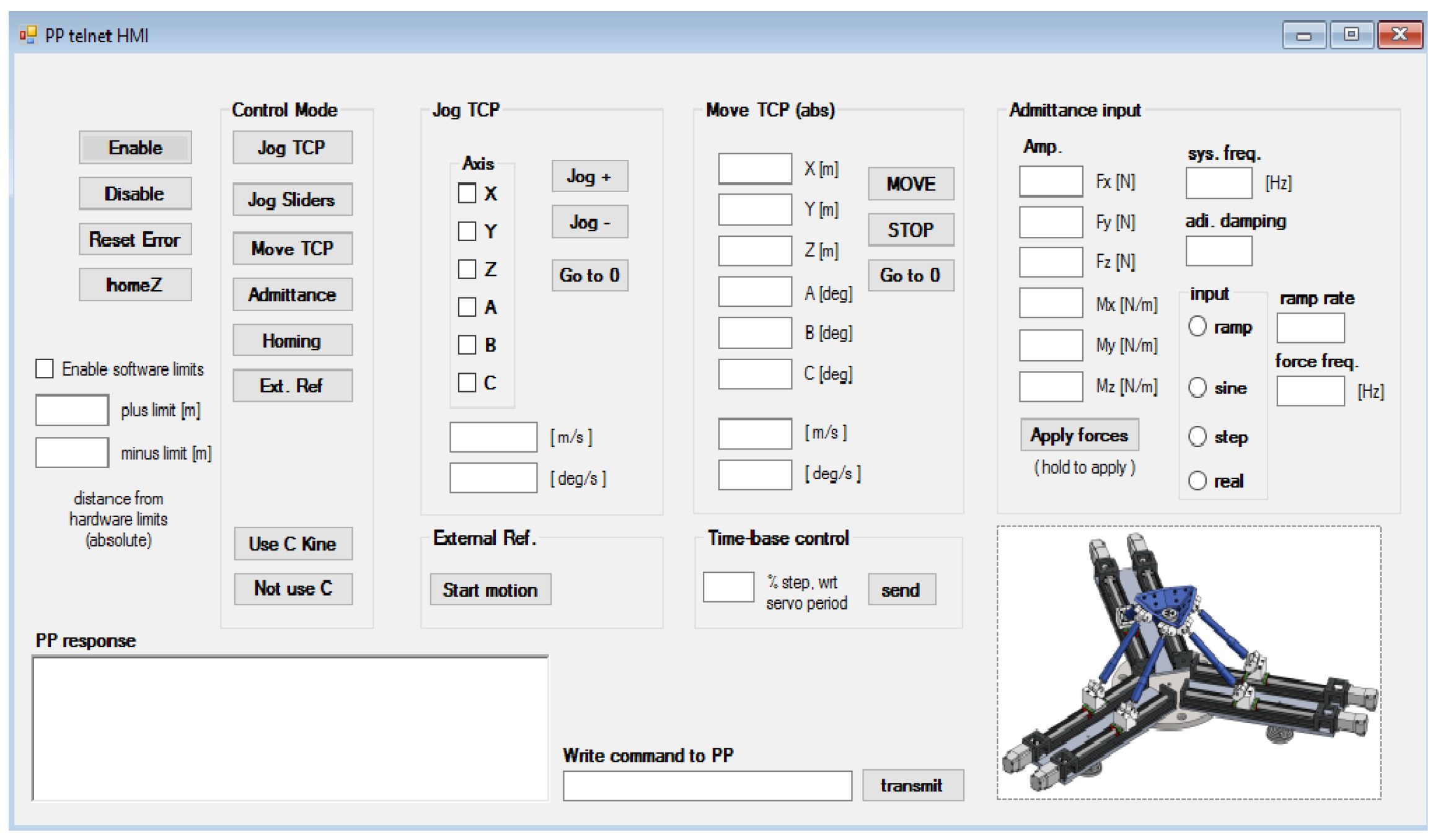
As shown in Figure 3, high level algorithms, such as trajectory planning within the motion planner routine and other control functions belonging to a specific control modality management, are executed at a rate of 0.4 kHz. The low level control involved with the servo loops, machine managing of the robot state, signals sampling and fault detection, all work at 1.6 kHz. Both control levels are written on a Power PMAC motion controller using a mix of a script language, developed by Delta Tau, and a C language. Both operated via an independent C# written Graphical-User-Interface (GUI), shown in Figure 9 that communicates with Power PMAC controller through a Telnet protocol. Every communication between Power PMAC, servo amplifiers and other controllers of the HIL setup, occurs through analogical signals. The overall software is organized as follows:
  • Two real-time script language PLCs manage the robot’s state machine. The first of these initializes all the robot parameters and the setup variables at the machine booting. Subsequently it runs the primary machine state. This routine checks for any errors, manages the change of state required by the user according to the current state of the robot and activates the secondary state machine. The latter is operated by the second real-time PLC and executes the request of state change forwarded by the primary machine state. It further manages the current state and the corresponding tasks, permits the debug procedure towards the user and executes the numerical forward kinematics C routine in order to transmit the real-time estimated pose.
  • All the commands by the users are transmitted to the primary state machine through a GUI written in C# and connected, via the Telnet protocol, to the Power PMAC variables saved in a shared memory.
  • Non real-time PLC language scripts manage the tasks relative to the operating modes. The more computationally demanding routines are written in C and executed by the main PLC with precise timing. Among these are the workspace safety limiting algorithms, acceleration saturation control, time-base control, signal processing and buffer management. Other tasks carried out by the main PLC are the debug procedure towards the state machine, the start/stop tasks of the motion program and the handling of possible exceptions.
  • The motion program is in the bottom level of this software architecture. This is the task with the highest priority executed between the servo interrupts. This routine deals with the motion curve generation, trajectory blending, segmentation time extrapolation, inverse kinematics and the accurate interpolation.
  • Underneath the motion program, the servo loops manage the signals coming from the encoders and transform the actuator position references into analogical torque commands which are transmitted to the Omron amplifiers via the DACs.
Note that PLC tasks, in Delta Tau terminology, are script language routines executed with typical PLC rules. Furthermore, the 0.4 kHz rate in the higher level routines means dealing with a move time of 2.5 ms. The segmentation move time is set at 1.25 ms, so that a three point extrapolation is effected by the continuous motion curve. In order to conclude the description of the software structure it is worth bearing in mind that the last interpolation stage works with servo amplitude periods of 0.625 ms, thus allowing one to add a midway point between the extrapolated ones. The time-base control works with a default index distance of 2, thus, in default conditions, the total delay due to the buffer management is four poses, for reasons of internal logic, and is equivalent to a 10 ms delay. The servo interrupt rate of 1.6 kHz allows one to have a time step for all real-time tasks equal to 0.625 ms.

5.1. Experimental Tests

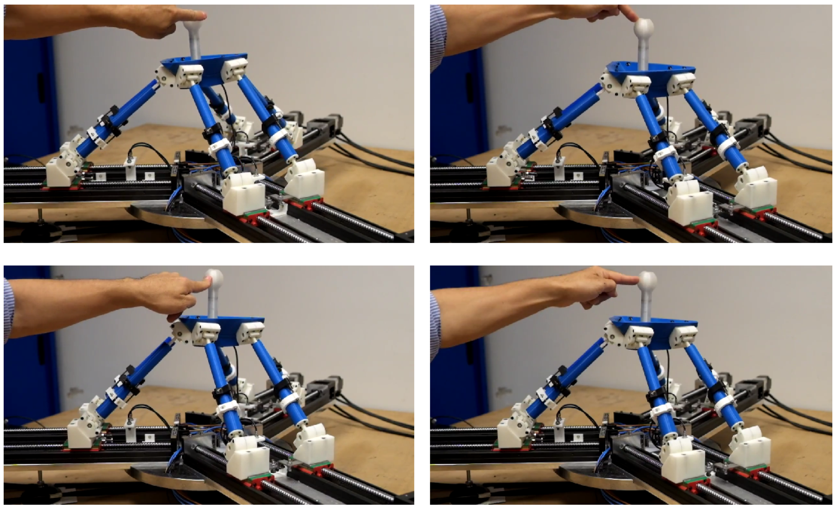
The simplified mathematical model developed for this test is set in accordance with the dynamic fundamental components of real floater movements which are limited to a range of 3 Hz bandwidth. Accordingly, a uniform stiffness is set among translational and rotational DOF, respectively of 5000 N m 1 and 200 N m r a d 1 . A dimensionless damping coefficient is fixed at 0.2, while the mass and the moments of inertia are calculated taking into account the natural frequencies of our interest. The robot has been stimulated by impulse loads applied on the joystick installed on a six DOF force/torque sensor, as shown in Figure 10. For the sake of brevity, the focus of the results presented in this analysis is only on the translational degree of freedom along the X axis aligned with the wind direction and describes the so-called surge movement. This is the degree of freedom under most stress in the entire system.
To analyse the experimental results, an ideal mathematical model of a six DOF mass-spring system has been developed and implemented in Simulink. The raw force signal measured from the field has been used as the input of this Simulink model. The force/torque analog signals have been filtered with a digital second order Butterworth low-pass filter with a 40 Hz cut off frequency. The ideal response of the system has been compared with the actual response of the controlled robot which includes the signal filtering and sampling procedure, trajectory planning, control loops and the estimated robot pose through the direct kinematics.
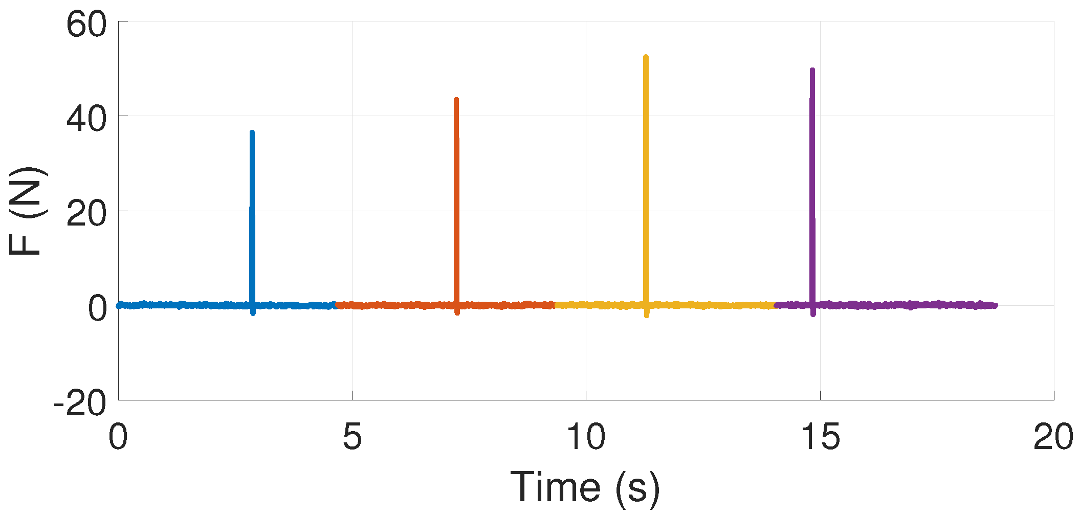
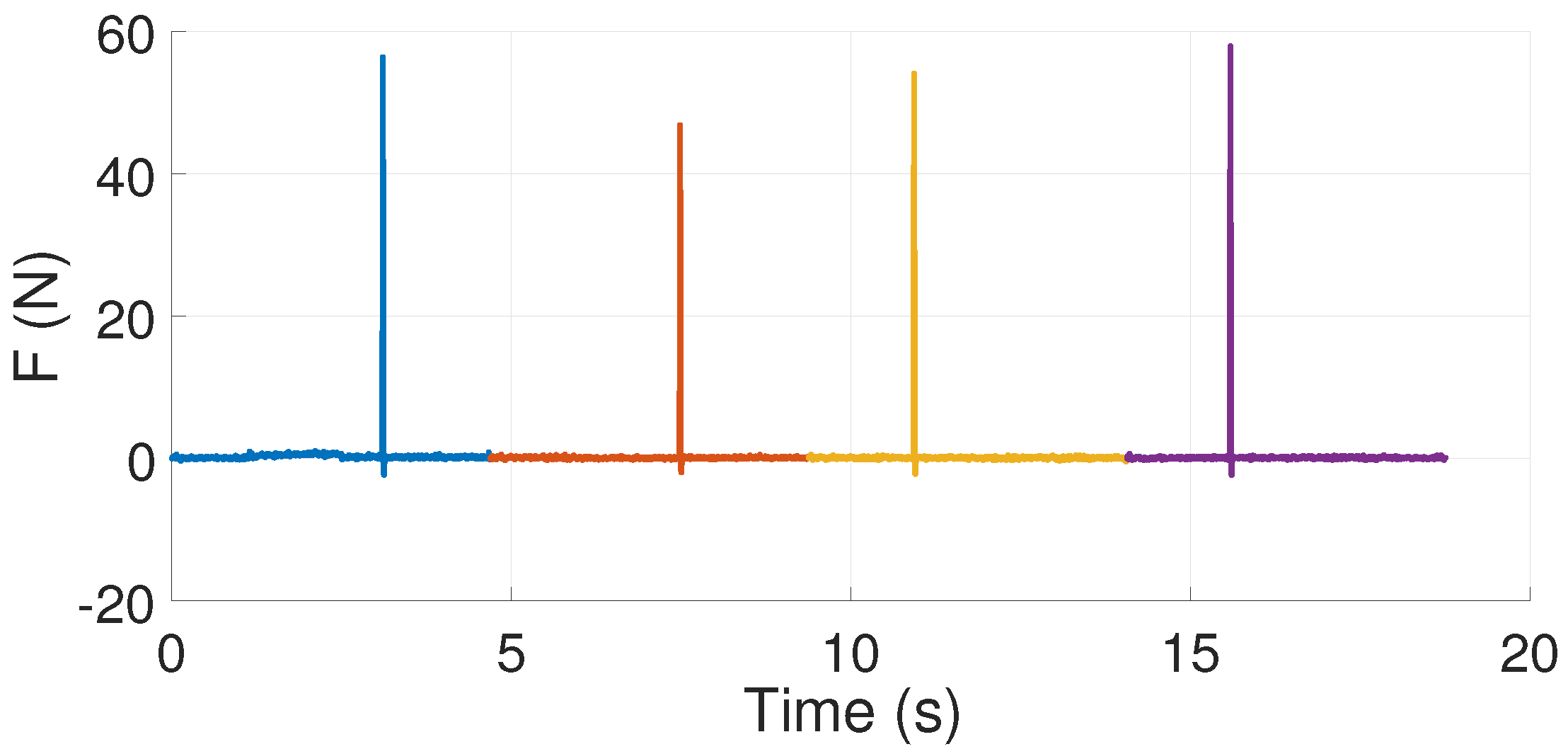
The experimental tests are based on the impulse response of the system. Four impulses are provided in a single load time history: each impulse response has been isolated and used to obtain the frequency response of both real and simulated system, whereafter an average frequency response is calculated to reduce noise influence. Note that the sample times of 0.625 ms and single time history segments of 7500 samples each provide a 800 Hz bandwidth response with a 0.2133 Hz resolution.

5.2. Results and Discussion

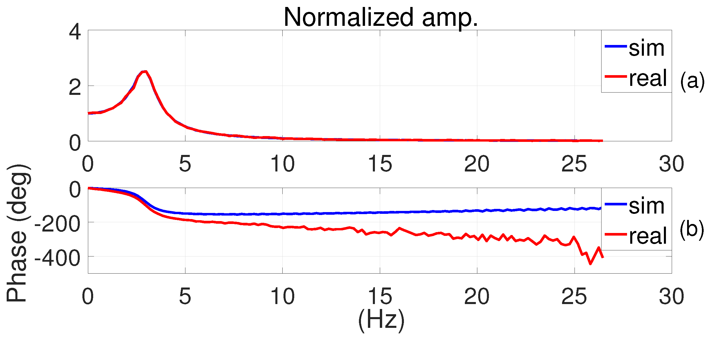
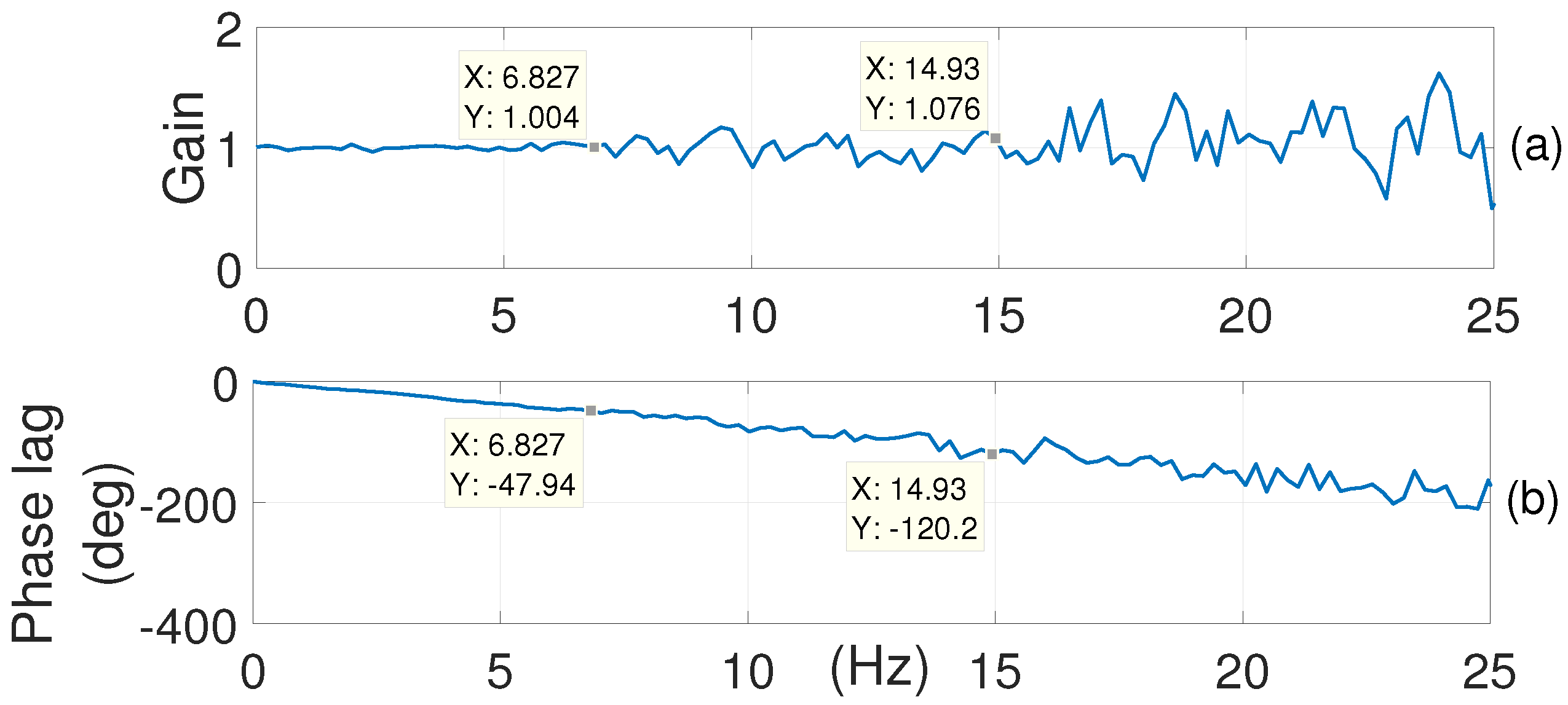
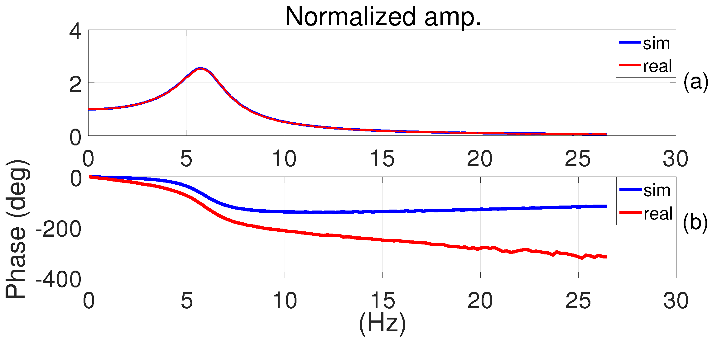
Figure 11, Figure 12 and Figure 13 show the results for a model with a 3 Hz natural frequency. In Figure 12, the comparison between an ideal and the real response of an input force is provided. The amplitude is normalized by multiplying the stiffness value in order to obtain the frequency response equal to 1 in the case of static load. The results at low frequencies show a highly accurate amplitude reproduction of the real response compared to the ideal one, while the phases show a significant difference. To better understand this effect, the transfer function of the control system compared to the ideal response is shown in Figure 13: this constitutes the measure of the controlled system transparency compared to the modelled dynamics. An ideal result would provide a unitary gain/zero phase lag, that is the controlled system emulating the modelled one perfectly. Figure 13 shows an almost unitary gain in a 7 Hz bandwidth, and a range of acceptable gains within a range of approximately 15 Hz. For the same frequency range, phase lag shows a linear behaviour, with a rise in slight oscillations between 7 and 15 Hz.
This observation is crucial for HIL test purposes. A unitary gain combined with a linear phase lag with respect to the frequency corresponds to a well emulated dynamic time response influenced by a constant delay: the controlled system seems to handle the amplitude very well, but adds a constant time shift. As long as this delay remains constant, and thus linear with the frequency, the controller, that integrates the dynamic equations, can compensate for this and obtain accurate results. To find confirmation of these results, another test was conducted increasing natural frequency to 6 Hz.
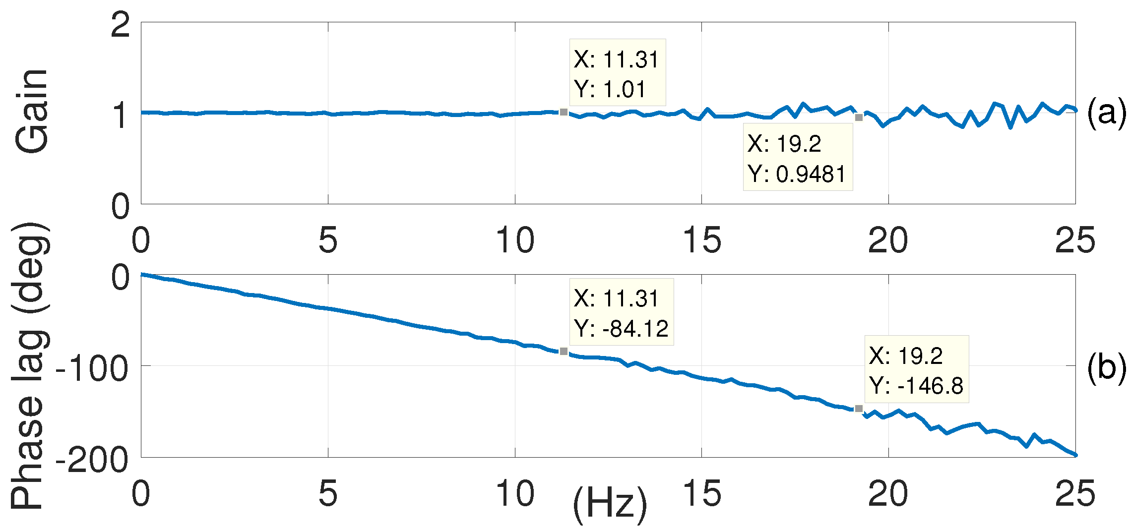
Figure 14, Figure 15 and Figure 16 show the behaviour obtained for a modelled system with a 6 Hz natural frequency on every DOF keeping the other dynamic parameters unchanged. The unitary gain region is extended to approximately 11 Hz and it is possible to use gains within the range of 20 Hz bandwidth. The trend of the phase response is linear within the extended bandwidth. The results obtained show a frequency bandwidth of the controlled system of at least 7 Hz, but an almost unitary gain is achievable within 11 Hz, nearly four times the bandwidth required for the HIL application of our interest. In this range, the robot has a really good transparency compared to the modelled system. Nevertheless, phase lag obtained requires some further considerations. Looking at the overall control software, the only significant sources of delay are the filtering stage of the force/torque sensor signals and the buffer management.
All the other control tasks not included in the buffer management timing routine, such as AD/DAC conversions, the phase-commutation loop and low level current loop, have marginal delay effects compared to the two previously highlighted. While buffer management delay is by definition constant and equal to 10 ms, the contribution of the Butterworth low-pass filter is greatly dependent on the cut-off frequency.
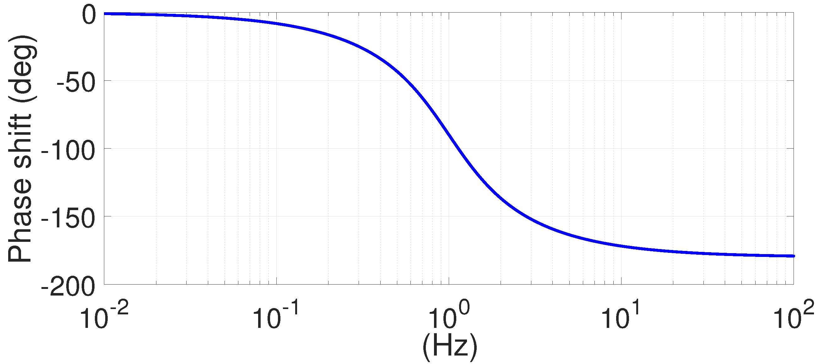
Figure 17 shows the trend of the phase shift with a cut-off frequency equal to 1 Hz and a logarithmic frequency scale. The relevant noise components of the signals acquired from the six DOF weighing scale are in the range from 50 Hz and multiples of 1 kHz, and depend on the disturbances induced by the motor power devices, while lesser noises are present at low frequencies due to the aliasing effects of the high frequency. Therefore, cut-off frequency has to be set low enough to filter the low frequency disturbances, but at the same time not too low so as not to shift the phase in the filtered signals. Furthermore, the filter phase lag should be linear in the operating range. This means a design of the cut-off frequency suitable for linear regression of the phase shift within the range of 7 Hz, or up to 11 Hz.
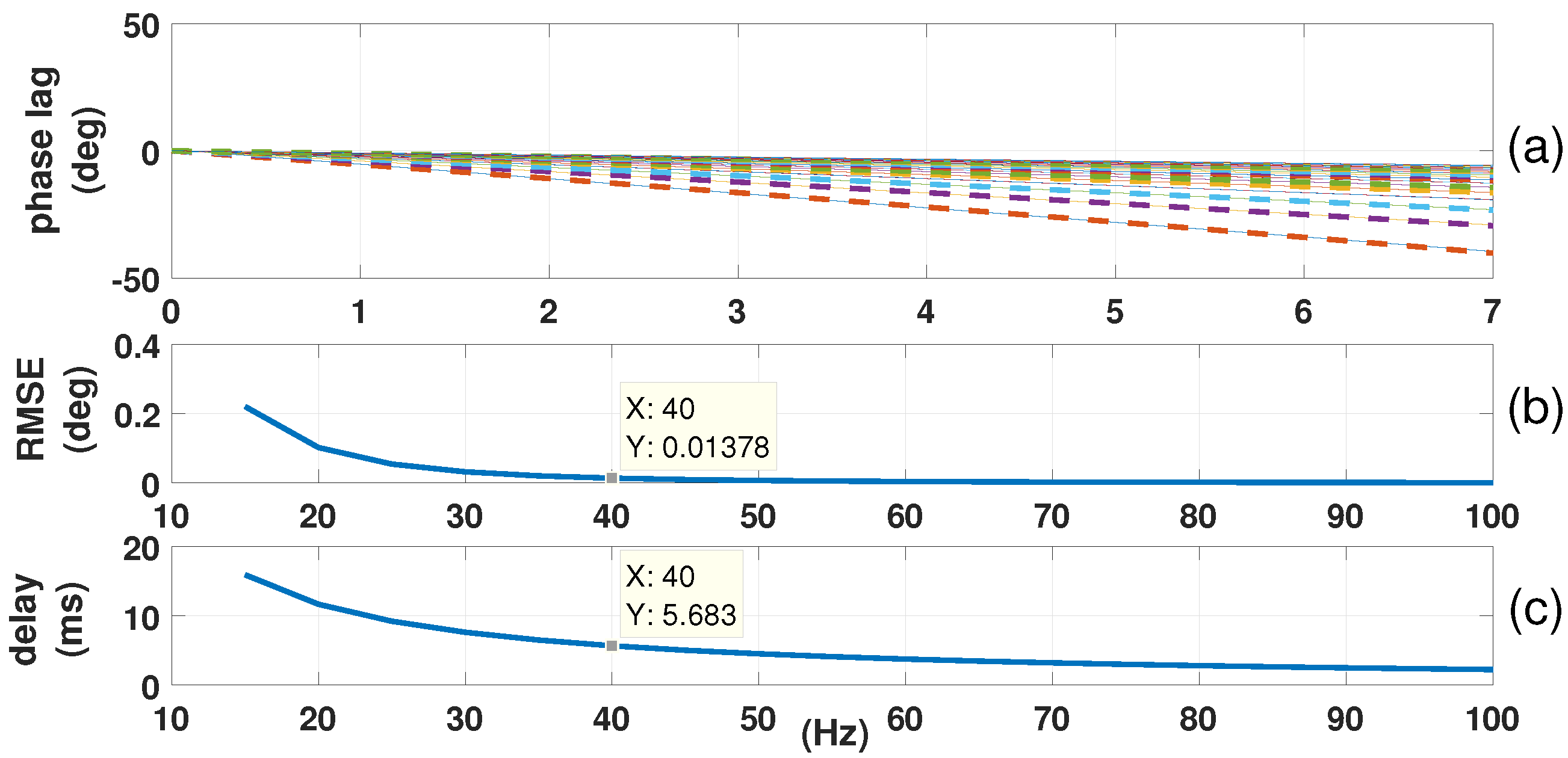
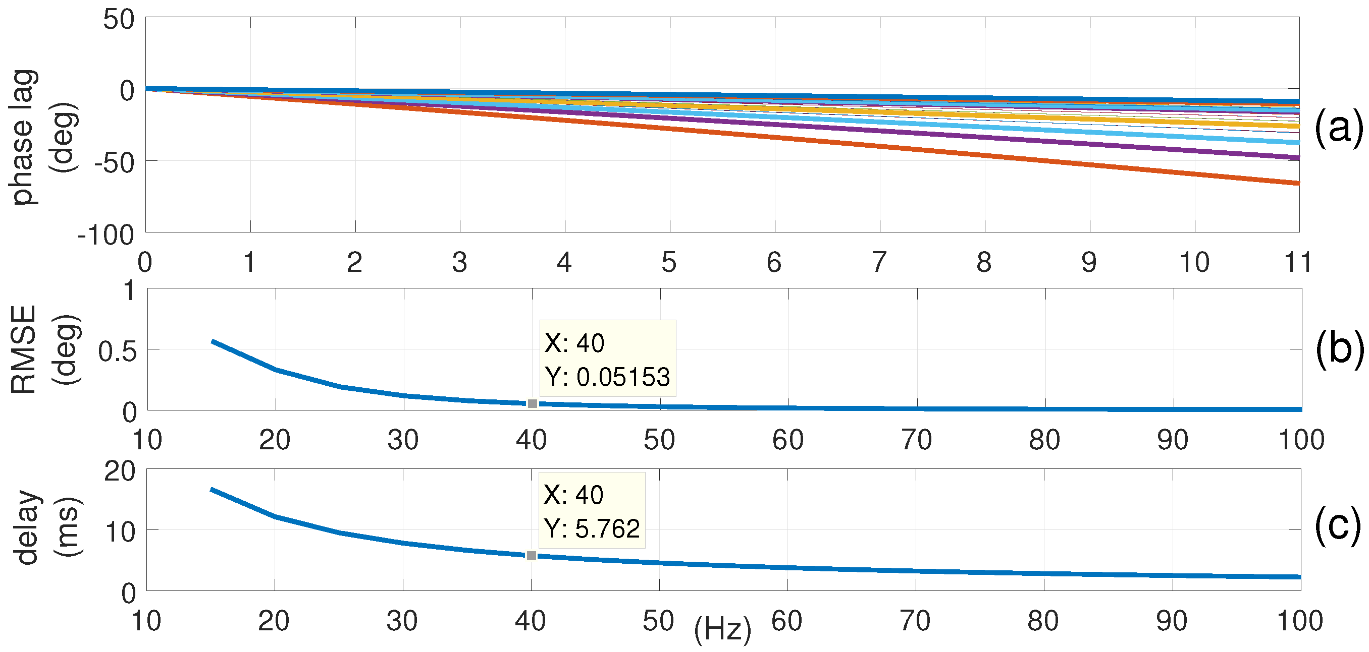
Figure 18c shows the phase shift at 7 Hz, transformed in a ms delay, in function of the cut-off. Figure 18b shows the Root-Mean-Square-Error (RMSE) resulting from the phase shift linear regression in the range of 0–7 Hz, in function of the cut-off. Figure 18a shows the comparison between the original phase shift trend (dashed) and the linear approximation (solid), within the range of 7 Hz bandwidth, for several cut-off frequencies from 15 Hz and units of 5 Hz.
Figure 19 shows the same analysis for the frequency range extended to the value of 11 Hz. Observing the data relative to the range of a 7 Hz bandwidth, a cut-off value of 40 Hz is an acceptable compromise, with an RMSE of 0.01378 ° and a constant delay of 6 ms approximately. To obtain a comparable linear regression performance within the range of 11 Hz, the cut-off frequency should be higher, but a 50 Hz motor power device disturbance obliges us not to exceed 40 Hz. Taking into consideration that the frequencies of our interest are below the value of 7 Hz, the performance achieved with this filter between 7 and 11 Hz is in any event satisfactory.
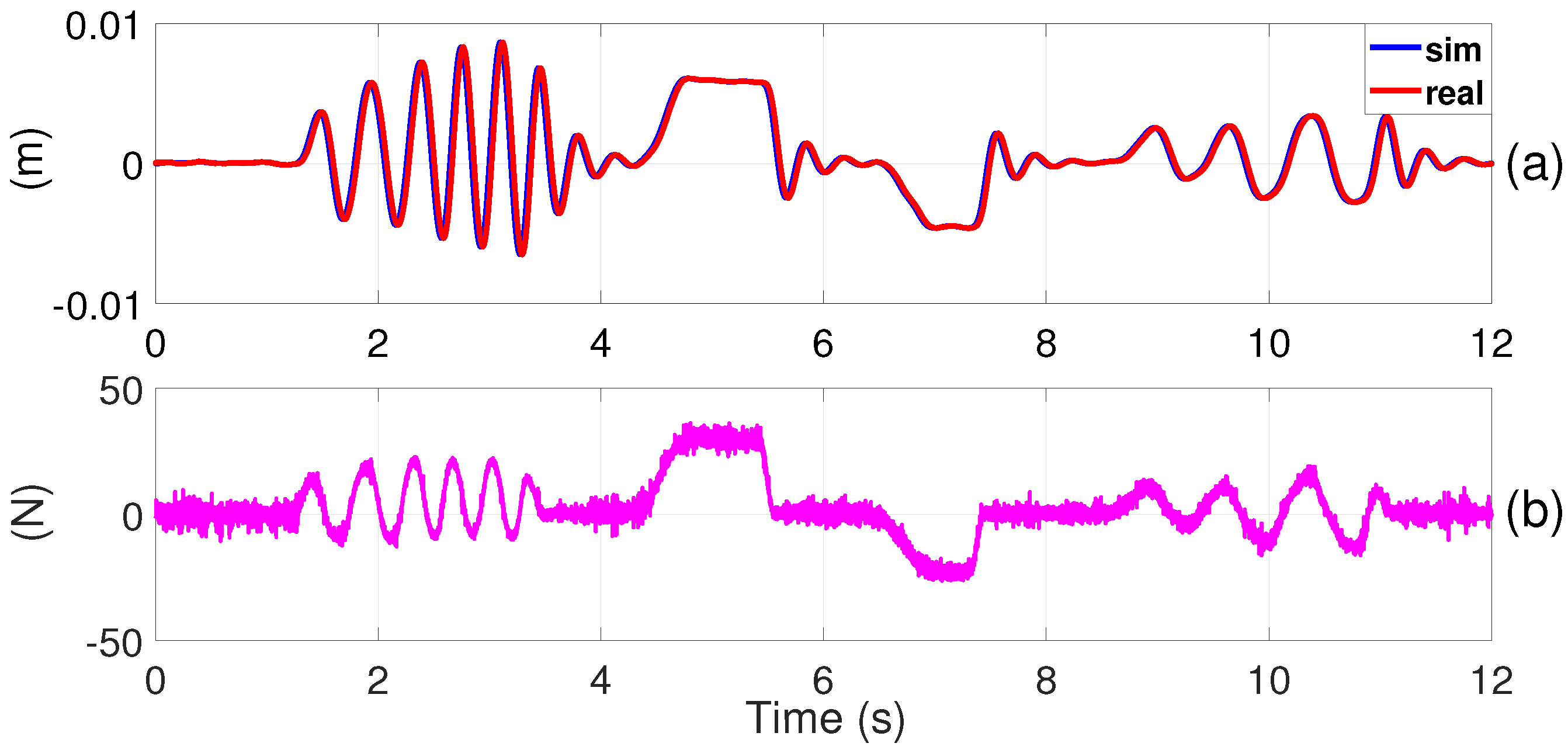
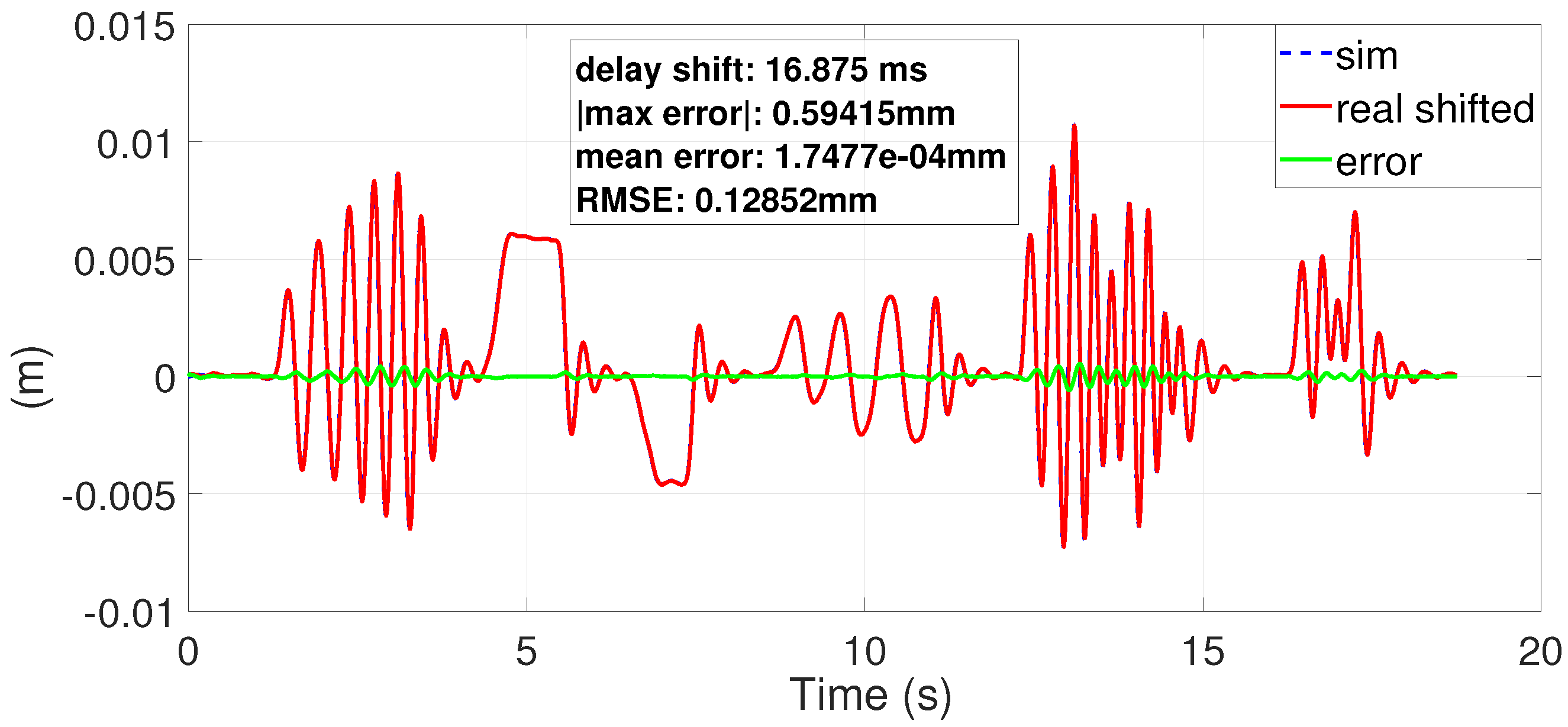
Finally, to compare motion time histories of the ideal and the real systems with the designed 40 Hz second order low-pass filter, the dynamic mass-spring model with a 3 Hz of natural frequency was tested with a random force input exerted through a joystick (Figure 20). Taking into consideration a combined delay of 27 samples (close to 16 ms, 10 ms buffer delay + 6 ms filter delay) and shifting the real response of this constant quantity, the comparison between the real and simulated motion time histories is really good, and confirms that major delay sources have a linear phase lag with respect to the frequency in the bandwidth under consideration. Figure 21 shows the results of this shifting: the overall reproduction of the required dynamic behaviour is ensured with high transparency. The delay is constant and allows one to compensate for it by means of the controller.

6. Conclusions

The particular Hardware-In-the-Loop application, originating from the LIFES50+ project for offshore floating wind turbines, has been presented. To achieve the challenging HIL requirements, a high performance software architecture based on PBAC force control has been implemented. This combines low level motion interpolation techniques with an efficient motion planning, based on a buffer management and Time-base control, as well as advanced high level safety algorithms that are implemented in a fast real-time control architecture.
Experimental tests have been conducted to evaluate controlled system transparency performances with respect to an ideal model dynamics. The 3 Hz bandwidth together with all the relative safety requirements have been satisfied. In particular, the proposed architecture assures both an optimal transparency behaviour and a constant, thus compensable time shift within the range of an 11 Hz bandwidth, that fully meets all the requirements of the project.

Acknowledgments

This project has received funding from the European Union’s Horizon 2020 research and innovation programme under grant agreement no 640741.

Author Contributions

H. Giberti and F. La Mura conceived the device, and designed the system and the experiments; F. La Mura and G. Todeschini performed the experiments; G. Todeschini realized the device, H. Giberti and F. La Mura analyzed the data; G. Todeschini contributed the control hardware device; and H. Giberti and F. La Mura wrote the paper.

Conflicts of Interest

The authors declare no conflict of interest. The founding sponsors had no role in the design of the study; in the collection, analyses, or interpretation of data; in the writing of the manuscript, and in the decision to publish the results.

References

  1. Fathy, H.K.; Filipi, Z.S.; Hagena, J.; Stein, J.L. Review of hardware-in-the-loop simulation and its prospects in the automotive area. In Proceedings of the SPIE, San Diego, CA, USA, 13–17 August 2006; Volume 1001. [Google Scholar]
  2. Carignan, C.; Scott, N.; Roderick, S. Hardware-in-the-loop simulation of satellite capture on a ground-based robotic testbed. In Proceedings of the 12th International Symposium on Artificial Intelligence, Robotics and Automation in Space (iSAIRAS), Montreal, QC, Canada, 17–19 June 2014. [Google Scholar]
  3. DeMore, L.A.; Mackin, P.; Swamp, M.; Rusterholtz, R. Improvements in flight table dynamic transparency for hardware-in-the-loop facilities. In Proceedings of the SPIE, Orlando, FL, USA, 12 July 2000; Volume 4027, pp. 101–112. [Google Scholar]
  4. Nunez, P.; Jones, R.; Shoop, S. High-Fidelity Ground Platform and Terrain Mechanics Modeling for Military Applications Involving Vehicle Dynamics and Mobility Analysis; Technical Report; Army Tank Automotive Research Development and Engineering Center: Warren, MI, USA, 2004. [Google Scholar]
  5. Isermann, R.; Schaffnit, J.; Sinsel, S. Hardware-in-the-loop simulation for the design and testing of engine-control systems. Control Eng. Pract. 1999, 7, 643–653. [Google Scholar] [CrossRef]
  6. Brünger-Koch, M. Motion parameter tuning and evaluation for the DLR automotive simulator. In Proceedings of the Driving Simulator Conference–North America 2005 (DSC NA CD-ROM), Orlando, FL, USA, 30 November–2 December 2005. [Google Scholar]
  7. Silvestri, M.; Confalonieri, M.; Andrea, F. Piezoelectric actuators for micro positioning stages in automated machines: Experimental characterization of open loop implementations. FME Trans. 2017, 45, 331–338. [Google Scholar] [CrossRef]
  8. Bayati, I.; Belloli, M.; Bernini, L.; Fiore, E.; Giberti, H.; Zasso, A. On the Functional Design of the DTU10 MW Wind Turbine Scale Model of LIFES50+ Project. J. Phys. Conf. Ser. 2016, 753, 052018. [Google Scholar] [CrossRef]
  9. Bayati, I.; Belloli, M.; Facchinetti, A.; Giappino, S. Wind tunnel tests on floating offshore wind turbines: A proposal for hardware-in-the-loop approach to validate numerical codes. Wind Eng. 2013, 37, 557–568. [Google Scholar] [CrossRef]
  10. Anglani, N.; Bossi, M.; Quartarone, G. Energy conversion systems: The case study of compressed air, an introduction to a new simulation toolbox. In Proceedings of the 2012 IEEE International Energy Conference and Exhibition (ENERGYCON), Florence, Italy, 9–12 September 2012; pp. 32–38. [Google Scholar]
  11. Bayati, I.; Belloli, M.; Bernini, L.; Giberti, H.; Zasso, A. Scale model technology for floating offshore wind turbines. IET Renew. Power Gener. 2017, 11, 1120–1126. [Google Scholar] [CrossRef]
  12. Bak, C.; Zahle, F.; Bitsche, R.; Kim, T.; Yde, A.; Henriksen, L.C.; Hansen, M.H.; Blasques, J.P.A.A.; Gaunaa, M.; Natarajan, A. The DTU 10-MW Reference Wind Turbine. Available online: http://orbit.dtu.dk/files/55645274/The_DTU_10MW_Reference_Turbine_Christian_Bak.pdf (accessed on 31 January 2018).
  13. Giberti, H.; Ferrari, D. A novel hardware-in-the-loop device for floating offshore wind turbines and sailing boats. Mech. Mach. Theory 2015, 85, 82–105. [Google Scholar] [CrossRef]
  14. Bayati, I.; Belloli, M.; Ferrari, D.; Fossati, F.; Giberti, H. Design of a 6-DoF robotic platform for wind tunnel tests of floating wind turbines. Energy Procedia 2014, 53, 313–323. [Google Scholar] [CrossRef]
  15. Fiore, E.; Giberti, H. Optimization and Comparison between two 6-DoF Parallel Kinematic Machines for HIL Simulations in Wind Tunnel; EDP Sciences: Les Ulis, France, 2016; Volume 45. [Google Scholar]
  16. Ferrari, D.; Giberti, H. A genetic algorithm approach to the kinematic synthesis of a 6-DoF parallel manipulator. In Proceedings of the 2014 IEEE Conference on Control Applications (CCA), Juan Les Antibes, France, 8–10 October 2014; pp. 222–227. [Google Scholar]
  17. Fiore, E.; Giberti, H.; Ferrari, D. Dynamics modeling and accuracy evaluation of a 6-DoF hexaslide robot. In Nonlinear Dynamics; Springer: Berlin/Heidelberg, Germany, 2016; Volume 1, pp. 473–479. [Google Scholar]
  18. Heinrichs, B.; Sepehri, N.; Thornton-Trump, A. Position-based impedance control of an industrial hydraulic manipulator. IEEE Control Syst. 1997, 17, 46–52. [Google Scholar] [CrossRef]
  19. Lawrence, D.A. Stability and transparency in bilateral teleoperation. IEEE Trans. Robot. Autom. 1993, 9, 624–637. [Google Scholar] [CrossRef]
  20. Shen, G.; Tang, Y.; Zhao, J.; Lu, H.; Li, X.; Li, G. Jacobian free monotonic descent algorithm for forward kinematics of spatial parallel manipulator. Adv. Mech. Eng. 2016, 8. [Google Scholar] [CrossRef]
  21. D’Antona, G.; Davoudi, M.; Ferrero, R.; Giberti, H. A model predictive protection system for actuators placed in hostile environments. In Proceedings of the 2010 IEEE Instrumentation Measurement Technology Conference, Austin, TX, USA, 3–6 May 2010; pp. 1602–1606. [Google Scholar]
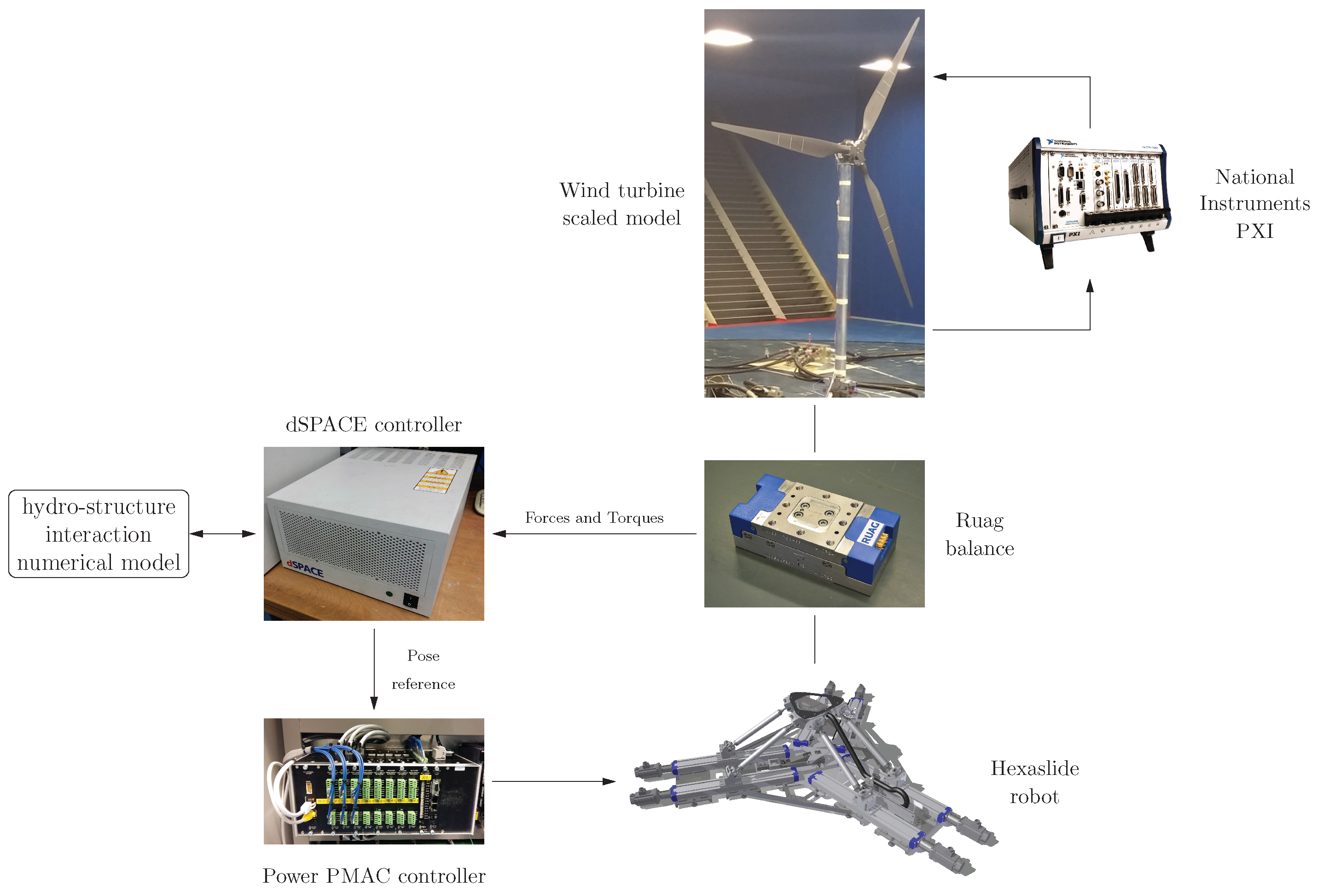
Figure 1. Hardware-In-the-Loop (HIL) control setup.
Robotics 07 00008 g001
Figure 2. (a) Scaled robot 3D rendering; (b) real scaled robot.
Robotics 07 00008 g002
Figure 3. Position-Based-Admittance-Control (PBAC) control scheme.
Robotics 07 00008 g003
Figure 4. Position controller scheme.
Robotics 07 00008 g004
Figure 5. Motion planner scheme.
Robotics 07 00008 g005
Figure 6. ASC scheme.
Robotics 07 00008 g006
Figure 7. Control scheme including all controllers.
Robotics 07 00008 g007
Figure 8. (a) Scaled machine; (b) Full scale machine.
Robotics 07 00008 g008
Figure 9. C# written Graphical-User-Interface. (GUI)
Robotics 07 00008 g009
Figure 10. Admittance moving example.
Robotics 07 00008 g010
Figure 11. Input force F x , 3 Hz test.
Robotics 07 00008 g011
Figure 12. Frequency response for the real and simulated systems with 3 Hz natural frequency. (a) Normalized amplitude; (b) Phase.
Robotics 07 00008 g012
Figure 13. Overall transfer function of the control system with respect to ideal response. (a) Gain; (b) Phase lag.
Robotics 07 00008 g013
Figure 14. Input force F x , 6 Hz test.
Robotics 07 00008 g014
Figure 15. Frequency response for the real and simulated systems with 6 Hz natural frequency. (a) Normalized amplitude, (b) Phase.
Robotics 07 00008 g015
Figure 16. Overall transfer function of the control system with respect to ideal response. (a) Gain; (b) Phase lag.
Robotics 07 00008 g016
Figure 17. Second order Butterworth low pass filter phase shift, cut-off frequency 1 Hz.
Robotics 07 00008 g017
Figure 18. Butterworth filter phase shift analysis, 7 Hz bandwidth. (a) Phase lag, (b) RMSE, (c) Dealy.
Robotics 07 00008 g018
Figure 19. Butterworth filter phase shift analysis, 11 Hz bandwidth. (a) Phase lag, (b) RMSE, (c) Dealy.
Robotics 07 00008 g019
Figure 20. Time response of real and simulated systems and load history, for random load and 3 Hz natural frequency.
Robotics 07 00008 g020
Figure 21. Shifted real response performances.
Robotics 07 00008 g021