1. Introduction
Companion robots are one of the more prolific instances of assistive technologies developed for servicing the elderly and disabled. Among the earliest key functionalities of these machines were to facilitate communication and entertainment via voice recognition, thus not requiring physical interaction for the patients to utilize their robots [
1]. Robots, such as the Autonomous Robotic Technology Multitasking Intelligent System (ARTeMIS), extend this functionality by also considering gesture detection and patient posture [
2]. Some variants are built for physical interactions too, especially those purposed for therapeutic sessions with cognitively disabled children, such as the humanoid Nao robot [
3]. Other robot systems are specifically created for more direct assistance, helping their disabled users to accomplish daily tasks and ambulation. The MATS service robot is an example of this, being a multipurpose robotic arm that attaches and detaches between the user’s wheelchair to a number of attachment points around the home to aid in mobility [
4].
Almost all companion robot systems share the same limitations as they are predominantly used in indoor areas. Current localization solutions that provide accurate position and heading, such as Global Positioning System (GPS), can only work outdoors, while indoor counterparts require expensive light detection and ranging (LiDAR) equipment and provisions for simultaneous localization and mapping (SLAM) [
5]. The autonomous indoor navigation problem is usually addressed using a combination of proximity sensors, depth cameras and machine vision, to keep track of both target users and the obstacles around them. While this may suffice for rudimentary routing around obstacles to reach a target destination, companion robots also contend with the challenge of human-following, which includes issues such as appropriate approach distances [
6] and being able to identify the correct user in a crowded environment [
7]. Finally, human-following is also impeded by hardware limitations, such as optical occlusion, refresh rate and processing power, which causes the robot to lose sight of the target [
8,
9,
10,
11].
This problem was faced by one such robotics project [
12] which aimed to develop a companion robot that acts as an autonomous watchdog to monitor a cognitively disabled child’s activities. The Companion Avatar Robot for Mitigation of Injuries (CARMI) utilizes a depth camera and a mobile robot platform to follow the child while tracking her actions for matching gestures indicative of injurious activities [
13]. The challenge was to design and implement an indoor navigation system for CARMI that utilizes the sensors that are already present within the robot, namely the depth camera, an array of ultrasonic ranging modules and an experimental active IR marker tracking system [
14].
2. Related Work
The robot navigation problem was described by [
15] to consist of World Perception, Path Planning & Generation, and Path Tracking. World Perception is achieved by selecting appropriate sensor suites which can provide suitable environmental feedback into the robot controller. One of the best suites to fit this need is Simultaneous Localization and Mapping (SLAM), which is a mature technology used to visualize the depth map of the surroundings via vision-based imaging devices, such as LiDAR. This information can be processed to provide the positions of obstructions, goals and the robot itself. The drawback is that SLAM suffers performance limitations in places with ambiguous structures [
16]. SLAM is also a computationally complex operation which incurs high processing costs [
17]. Reference [
18] indicated that SLAM also suffers when its sensory devices are subjected to abrupt and unpredictable motions. As the CARMI sensors are all mounted within the same mobile platform, a non-complete mapping method may be preferable. Reference [
19] demonstrated that it is possible to perform partial mapping by relying on a single rotating range-finder and transforming the data into a relative depth-snapshot of the environment. This method may be applicable using CARMI’s rotating depth camera setup.
Path Planning & Generation is a long-standing research area, with both classical and heuristics approaches still being heavily applied to avoiding collisions and reaching goal positions. Human-following appends an additional layer of difficulty, in that the robot has to reach, but maintain a certain distance away from a moving goal. Reference [
20] describes the path planning system as either “passive” or “anticipative”. An “anticipative” system considers how a human target may move, using a velocity model [
20] or a version of Monte Carlo algorithm [
17,
21], dynamically modified using either Kalman filters, neural networks, fuzzy-logic or similar combinations [
22,
23]. These methods also impose significant processing costs, so it may be best for the CARMI navigation model to be “passive”, in which the robot responds reactively towards landmarks or changes to its environment [
24].
Finally, the combined execution of path generation and tracking depends on whether a navigation system involves global or local planning [
23]. Global planning involves acquisition of a complete environment map, so that a shortest-path can be drawn using A* or Dijkstra’s algorithm [
25,
26]. These are practiced and robust methods, but a complete map is difficult to acquire without SLAM or some form of embedded environment [
27] to aid path construction. For CARMI, a local planning strategy is ideal, because only a momentary snapshot of the immediate environment is needed. While a heuristics approach such as Ant Colony Optimization is best for this kind of non-deterministic problem (NP-Completeness) [
15], the memory requirements will clash with CARMI’s activity tracking needs. Instead, a topological approach that emulates the event-based reactions of humans is ideal, based on the work by [
24]. Instead of Quick Response (QR) patterns, the CARMI model will utilize a fusion of depth camera and ultrasonic ranging snapshots as the natural landmarks, while the locked subject position will take the place of artificial ones.
3. Navigation Concept and Algorithm
To recap, this research aims to develop a navigation model that applies to CARMI, an indoor companion robot that was created for mitigating injuries in cognitively impaired children [
28]. CARMI’s autonomous activity tracking system relies on a depth camera, a body tracking system, an experimental active IR marker tracking system, and an array of ultrasonic ranging sensors [
13] mounted on a non-holonomic platform with variable drives.
Therefore, this article documents the creation of an indoor robot navigation model that seeks to improve human-following and obstacle avoidance. It accomplishes this by locking onto the relative target position and acquiring the depth landscape between them. This sensor fusion is used to guide the relocation of the robot so that the human target is within the tracking system’s optimal zone of detection (which is within a 60° cone in front of, and 1–3 m away from the depth camera). In the event of encountering an obstruction, the robot controller uses this data to decide whether to start avoidance maneuvers from the left or right of the object. After this, any choice of local pathfinding algorithm may be used. This translates into the two phases of the navigation algorithm: subject locking and pathfinding. The details of this algorithm are explored in the following section.
The design of the CARMI robot controller incorporates the modular approach from [
24], so any indoor human-following robot that is equipped with the same template may be applied with it.
3.1. Subject Locking and the Active IR Marker Tracking System (AIRMT)
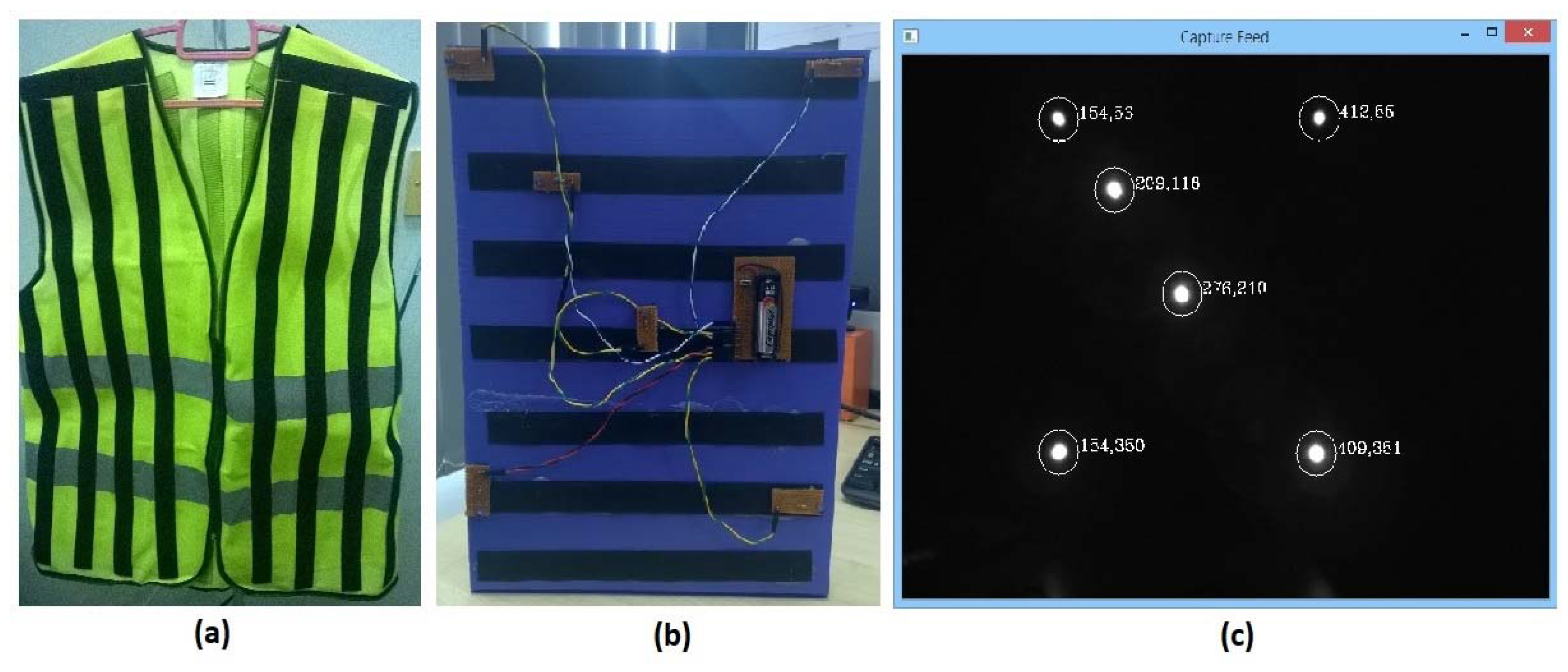
The Kinect optimal tracking zone problem is initially treated with an assistive technology solution that integrates wearable electronics and vision-based marker tracking. This system consists of a camera with a modified high pass filter and a vest arrayed with Infrared (IR) Light Emitting Diodes (LEDs) (
Figure 1) [
12]. The idea is to capture the pattern of LEDs and use template matching to approximate the relative angle the subject (wearing the vest with active LEDs) is facing. This information be used as a feedback mechanism to control the motion path for the robot to navigate to, so that it will face the subject from the front. The system’s raw tracking of active IR LEDs was effective at trifold the template matching distances. This allows the system to visibly identify the position of the vest relative to its viewing space, if the wearer is within line of sight and is in the same room. This concept evolved into a method for screening identified Kinect bodies for the one that represents the target.
With the incorporation of the enhanced version of the depth camera, the device can now fully track a total of six people with complete body motion analysis. If the target person is within the optimal tracking zone, they will be assigned a body index. Unfortunately, crowded environments with overlapping body silhouettes can confuse the system and cause the subject to be switched to another index. This can also be caused by momentary loss of visibility or the presence of obstacles that produce false detections. In applications, such as CARMI, where there is a single designated target subject, the switched index problem will make the robot continue tracking the wrong people, defeating its primary function.
Subject locking solves this by making use of the AIRMT as a redundant system that overlaps the Kinect’s body tracking. The AIRMT view-space marker position can be transformed into the Kinect’s view-space and used to identify the correct body that represents the subject. This transformation process is explained as the following.
3.1.1. Remapping the Origin for AIRMT and Kinect View-Spaces
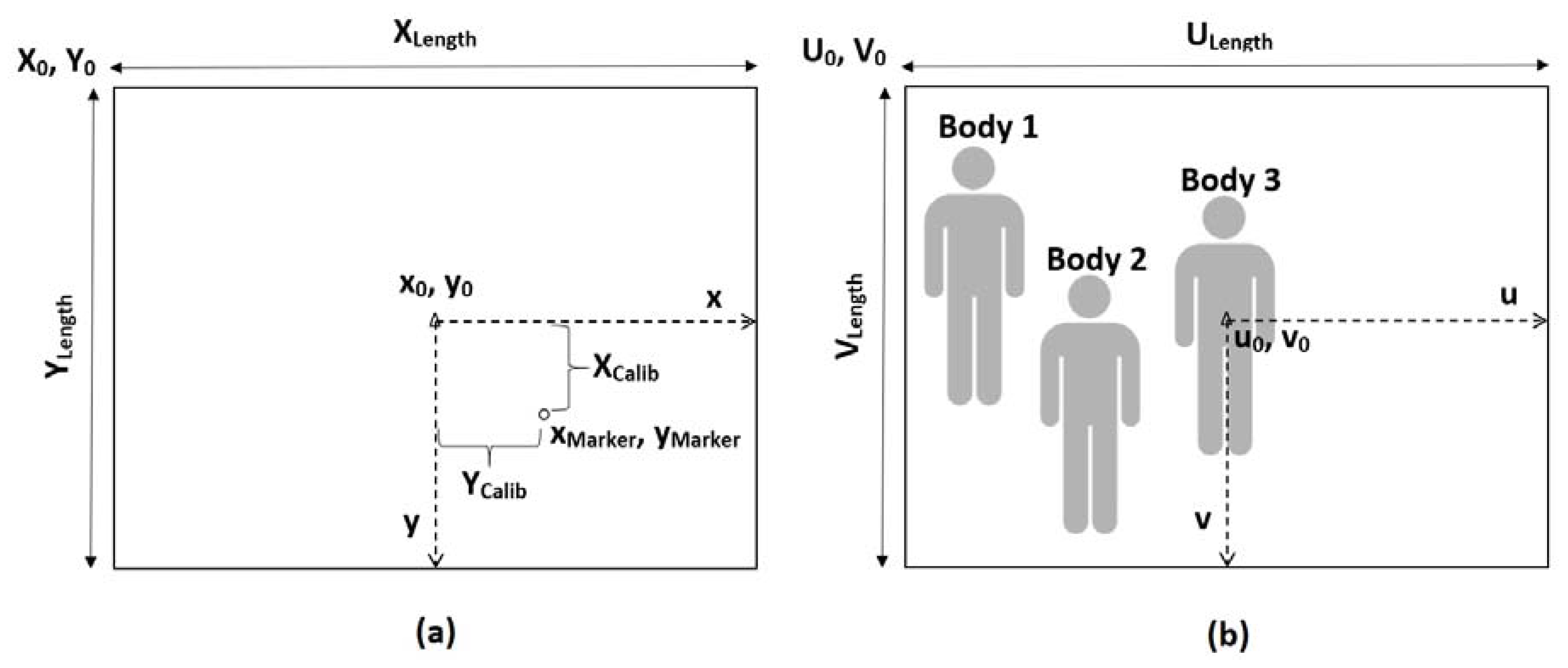
The AIRMT IR Camera and the depth camera share the same coordinate system and origin, located at the top left of the image frame (illustrated in
Figure 2). Raw coordinates are expressed in
for AIRMT and
for the depth camera, so the space dimensions are
and
respectively. Their origins are represented by
and
.
However, both exist as separate hardware devices, so they have different fields of view (FOV) and viewing angles. Calibration of multiple vision-based hardware is a complex process and the configuration variables change as alternate devices are used. To accommodate the modular nature of the model, only the extrinsic parameters are to be calibrated, notably the camera centre, as the new origin to define the unified three-dimensional (3D) coordinate systems for both depth and IR cameras. The intrinsic characteristics for both devices had to be roughly approximated by mounting both devices as closely as possible, while positioning them to focus on the same point. The loss in accuracy is compensated by the closed-loop corrections done by the turn-table mechanism in response to the distance between the target and the camera centre.
The first step is to create a unifying point of reference by readjusting both planes to use an origin situated in the middle of the view-spaces, referred to as the midpoint-adjusted origins
and
. These are calculated in Equation (1). Thus, every raw coordinate
or
supplied by both systems will be mapped using Equation (2), the results expressed as
or
.
3.1.2. Resolving the IR Marker Position
The active IR marker on the primary subject’s vest exists physically as multiple IR LEDs, which show up in the AIRMT view-space as individual blobs. The coordinates of the blob centers are used as marker points, expressed as
after being mapped. It is assumed that the general position of the marker-wearer is indicated by the centroid of all visible marker points, which is calculated in Equation (3).
3.1.3. Finding the Calibration Offset and Scaling Factor
Since both optical systems exist as individual physical devices, their separate placements will mean that a target centred in one view-space is not necessarily centred in the other. Different lens configurations also indicate that translation of a subject in one view-space is not identical to its movement in the other. This algorithm assumes these as a linear problem, considering that both devices should be ideally mounted as close to each other as possible for easier view-space overlapping.
First, the subject is positioned at the origin of the depth camera view-space (as in Body 3 in
Figure 2b) and the resulting marker position
from the AIRMT view-space indicates the calibration offset (as shown in
Figure 2a). This produces the offset-calibrated marker position
as in Equation (4). Then, the subject is relocated so they are near the edge of the Kinect view-space. The new AIRMT marker position is used in Equation (5) to calculate the translation ratio of the subject between both view-spaces. This ratio will be applied to future AIRMT coordinates as the scaling factor
.
3.1.4. Transforming the Active Marker Position and Finding the Primary Subject’s Body
After calibration, the AIRMT marker coordinates are applied with both the calibration offset and scaling factor (Equation (6)) to transform them into the depth camera FOV equivalent position
. The distance
between each depth camera-detected body
from this marker point is examined (Equation (7)), to determine the body that corresponds the closest to the primary subject (Equation (8)). The rest of the navigation system may now continue to operate while “locked on” to the primary subject’s body
.
3.2. Pathfinding Strategy and the Path Decider
The companion robot behaviour is intended to consist of two concurrent state machine loops. The first loop takes the primary target’s position offset from the midpoint origin as the error input for the closed-loop control of the turn-table platform. The turn-table will constantly swivel towards the target, ensuring that the Kinect and AIRMT camera is centred on the primary target. If the target is out of sight, the robot is to halt all operations and scan the room until she is reacquired. Once locked onto the correct subject, the Kinect body tracking system can return an estimated distance between her and the robot.
The second loop determines the robot’s locomotive actions, based on the information from the first loop (whether the target is locked on, how far she is, and if the robot body is aligned with its head). If the target is within the optimal tracking zone, the robot will realign the body with the head before halting all motion. Otherwise, it will move forwards or in reverse as an approach action until the target is in the desired position. The problem arises when the robot encounters an obstruction while attempting the approach.
There is a myriad of possible solutions to plotting a route around obstructions using only an array of onboard proximity sensors, and any of these can be incorporated into the navigation system. For the purpose of the initial implementation, the selected routing method is based on the Wandering Standpoint Algorithm (WSA) [
29]. The robot stops at waypoints to re-evaluate the positions of itself, the obstruction and the goal before deciding on the next waypoint to move to (
Figure 3a). This model was chosen because it does not rely on readily available maps and only depends on the perception of its immediate surroundings.
The second phase (pathfinding) of this navigation model is concerned with a fundamental problem that simple, reactionary methods such as the WSA share, which is the inability to determine whether a chosen waypoint will lead to a shorter path. This problem is largely solved using SLAM and other means of getting a complete overhead snapshot of the room. With its absence, CARMI has to make an informed decision to begin circumventing the obstruction from the left or right, by examining the input from the proximity sensors, the relative direction of the target from the robot, and the depth configuration of visible mid-range obstructions between them. In the case of
Figure 3a, the pathfinding phase is responsible for reviewing all sensory data to determine if path A will lead to a shorter and less-obstructed path to the goal.
3.2.1. Potential Field Method
The pathfinding phase takes inspiration from the Potential Field Method (PFM) [
30], visualizing obstructions radiating repulsive forces while the goal position emits attraction. The environmental map forms a field of forces, enabling the system to chart a path following a flow between the robot and goal position. Khatib describes the environment (Equation (9)) as an artificial potential field
that is the sum of potential fields exuded from the goal
and obstructions
. Each cell in the map will essentially hold a force value that is influenced by directional magnitudes of repulsive obstructions and the attraction from the goal.
Although CARMI’s navigation model lacks input from mapping services, the concept of repulsive and attractive forces can be applied to the current set of sensor feeds to influence the robot’s tendency to favour a left or right path, to begin maneuvering. Repurposing the PFM (Equation (10)), a 1D array can represent the horizontal perception of the environment around the robot (
Figure 3b), with each cell
representing a total sum of attractive (
and repulsive
forces emanating from that direction.
Because the magnitude of forces is directly related to the perceived proximity between visible elements (obstructions and the target) and the robot, a better analogy can be drawn from Coulomb’s Law, which describes the interaction of charged particles (Equation (11)). The law posits that the interactive force depends on scalar product of both charge magnitudes the distance between them and their polarities plus external factors . The scalar force is inverse to the square of the distance, meaning that the experienced force diminishes as the particles become further apart. This can be reinterpreted to describe the component forces for this navigation model. The resultant equation (Equation (12)) defines a general force format that consists of the type of source (either repulsive or attractive), the proximity of the source to the robot and a calibration constant
3.2.2. Transforming the Depth Array
The raw data from the depth camera requires some processing to transform its 2D depth map into a single dimensional array. The loss of 2D data means that the system will lose the advantage of sensing obstruction shapes, but the navigation system only requires the horizontal component of the depth data. Hence, the resultant array
cells contain the mean depth total
of each column of the map (
Figure 4). Equation (13) also shows that top
and bottom
trims of the
depth map are excluded from the calculation, so objects too high or low are omitted from the depth camera’s consideration.
Applying Equation (12)’s general form with a negative transforms it into a repulsive force (Equation (14)). The mean depth total is used as the distance variable so each cell in array now contains a numerical representation of repulsive forces emanating from that column of the depth map. The constant is used to experimentally calibrate the system, so that the closest possible obstruction in a direction cell has a value approaching −1.
3.2.3. Transforming the Perimeter Proximity Sensors Array
As visualized in
Figure 3b, the perimeter proximity sensors data can be arranged into an array that represent the distances of obstructions surrounding the robot body. However, this navigation algorithm assumes that the array is centred on the direction that the robot’s head is facing. Since the robot body and head can be misaligned when initiating the pathfinding phase, an offset and trim to the sensor data need to be applied, based on the physical placement of the sensors and the turn-table position. First, the raw perimeter sensor data is acquired
and populated into the Perimeter Proximity Sensors Array
, according to Equation (15).
represents the calibration constant that is used to adjust the shifting of array element indices, so that the data set is now aligned with the robot head position
. The dimension of array
must correspond with the size of array
, but it is possible to be exceeded by the
array. In such cases, the data set is trimmed according to the direction of the head misalignment (Equation (16)). Finally, the contents of array
are adapted to the general force form in Equation (11) as repulsive force magnitudes (Equation (17)). The constant
is present as a calibration constant to experimentally adjust the weight of array
so its contents do not exceed the negative-1 force threshold.
3.2.4. Transforming the Primary Target Position Array
The third force component is transformed from the relative position of the primary target, as acquired from the subject locking phase. The contents of the target position array
correspond to the distance between the horizontal coordinate of the subject and the Kinect view-space midpoint origin (
Figure 5). Therefore, the closer the subject is positioned to the middle of the frame, the stronger the attractive force becomes.
By collecting the primary target’s horizontal position
from the subject locking phase, array
elements
are populated, using the general force form (Equation (12)) and adapting it to become an attraction force. The distance between the current index
and the cell representing the primary target
is used as the force form distance variable
, as shown in Equation (18). The element contents are incremented by 1 to prevent division-by-zero situations. Equation (19) shows the full form of the attractive force magnitudes stored in array
, followed by the calibration constant
for experimental adjustments, to ensure that the highest force values are capped at 1.0.
3.2.5. Resolving the Sum of Forces and Choosing a Direction
The final stage in the pathfinding phase is to sum the force magnitudes from the depth, perimeter and target arrays as array
(Equation (20)), along with a calibration factor for experimental adjustment of the force sum subsequent impact on the robot’s state machine behaviour. Elements in both halves of array
are then summed (Equation (21)) to determine which corresponding side incurs the most positive tendency, based on the findings from the mid-range depth, short-range perimeter proximity and relative target position (Equation (22)).
The result of the pathfinding phase decides the side that CARMI will pan towards before commencing with a suitable wall-following algorithm to maneuver around the obstacle. Selection of the algorithm depends on its suitability towards the method of robot ambulatory means and the environment it is designed to move in.
4. Robot System Implementation
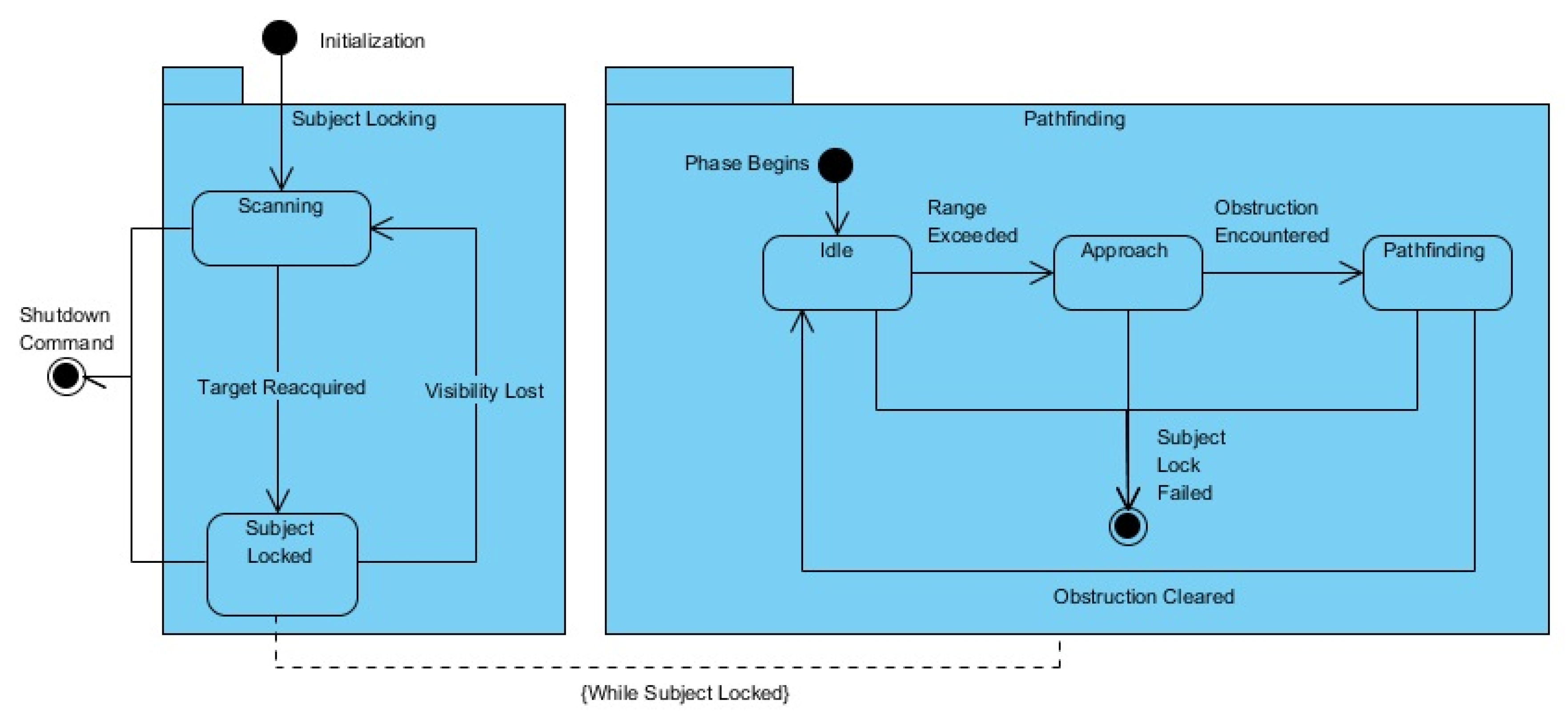
The concept of the navigation model used for CARMI can be distilled into two state machine loops (one for each of the phases) running concurrently, as depicted in
Figure 6. Upon robot initialization, the subject locking loop is activated first, scanning the room for the primary subject then locking-on when successful. The state machine then flags for activation of the pathfinding phase loop, that performs the range check and appropriate idle/approach actions. During the ‘approach’ state, proximity of obstructions will trigger the path decider to evaluate the environment (according to pathfinding phase of the navigation model) before proceeding with a selected method for maneuvering around the object. The pathfinding loop is deactivated whenever subject-locking fails, and is reactivated once the primary subject has been reacquired.
The entire CARMI robot system has been implemented using Microsoft Robotics Developer Studio (MRDS) version 4 for experimentation in both software simulation and hardware testing. MRDS is a distributed service-based robot control framework and integrated development environment operating under Microsoft Windows [
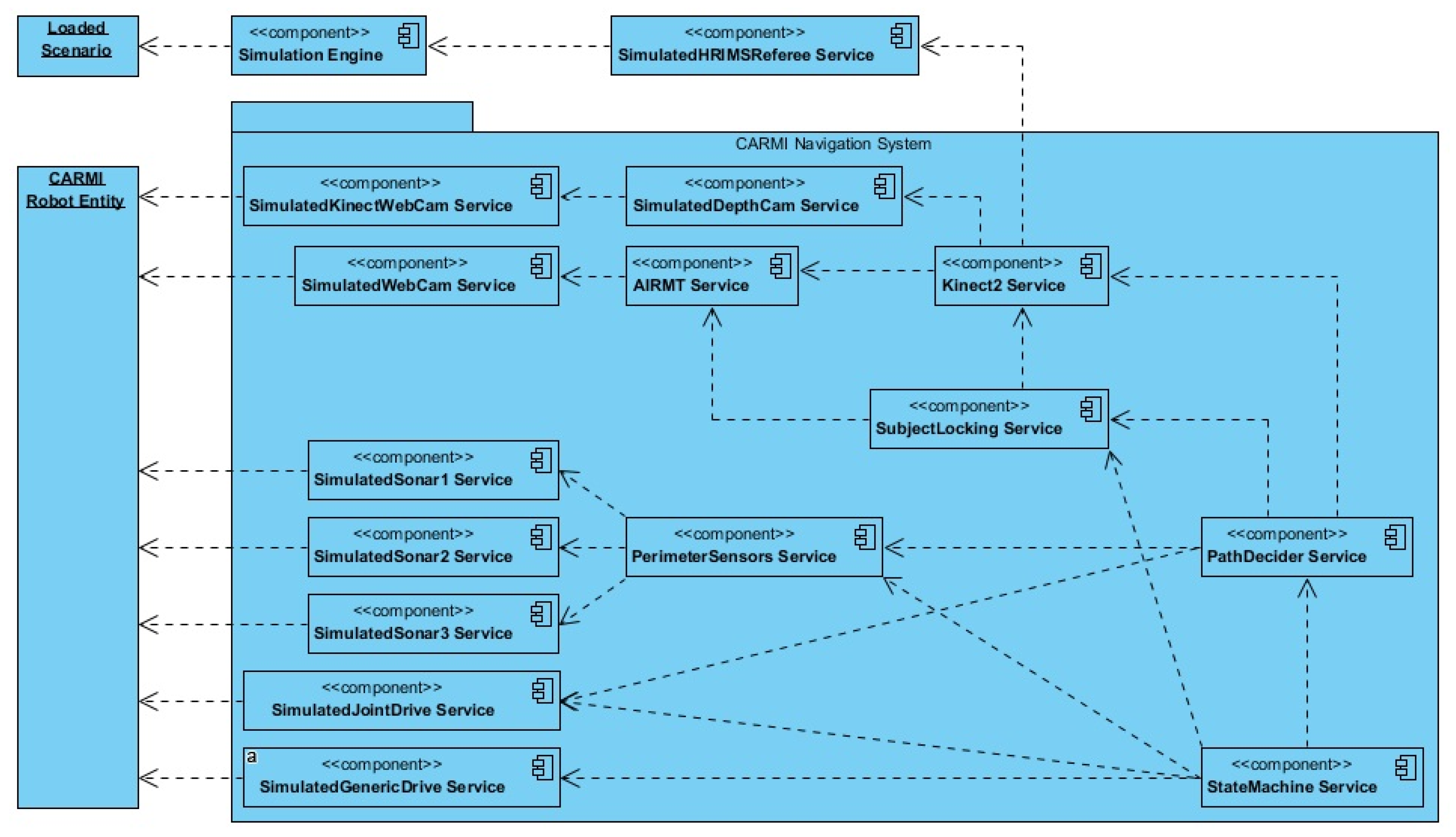
31]. MRDS was the chosen framework to accommodate compatibility issues between Visual Studio and the Kinect SDK. However, MRDS has ceased being updated since 2012 and considerable effort was spent in adapting the legacy framework to operate in the current version of Windows. The MRDS robot projects consist of a Decentralized Software Services (DSS) manifest that organizes and runs individual services in real time. The singular purpose of a service is to interface with or simulate a sensor, actuator, state machine, or other component of a robot’s behaviour and operation. While there is a suite of generic services available for tutorial use, the majority of CARMI were manually constructed, as outlined in
Figure 7.
A total of 15 custom services were constructed during the software development cycle for CARMI, including scenario files that must be graphically built to run in MRDS’s included Visual Simulation Environment (VSE). The CARMI DSS manifest begins with a referee service, which engages the VSE simulation service and creates the runtime according to a supplied scenario file. Crafted component services for the AIRMT camera, Kinect camera, ultrasonic ranging sensors, variable drive and the turn-table actuator are linked to the simulated CARMI robot entity. This is followed by implementing emulations of the AIRMT tracking system and Kinect and pairing them with the appropriate component services. The tracking systems data are then supplied to behaviour-control services, which consist of the subject locking, path decider and main state machine services.
Meanwhile, the primary subject (a child model wearing the IR beacons amongst several identical decoys) is represented by a child robot entity, which is linked to appropriate services that enable manual steering using a game controller.
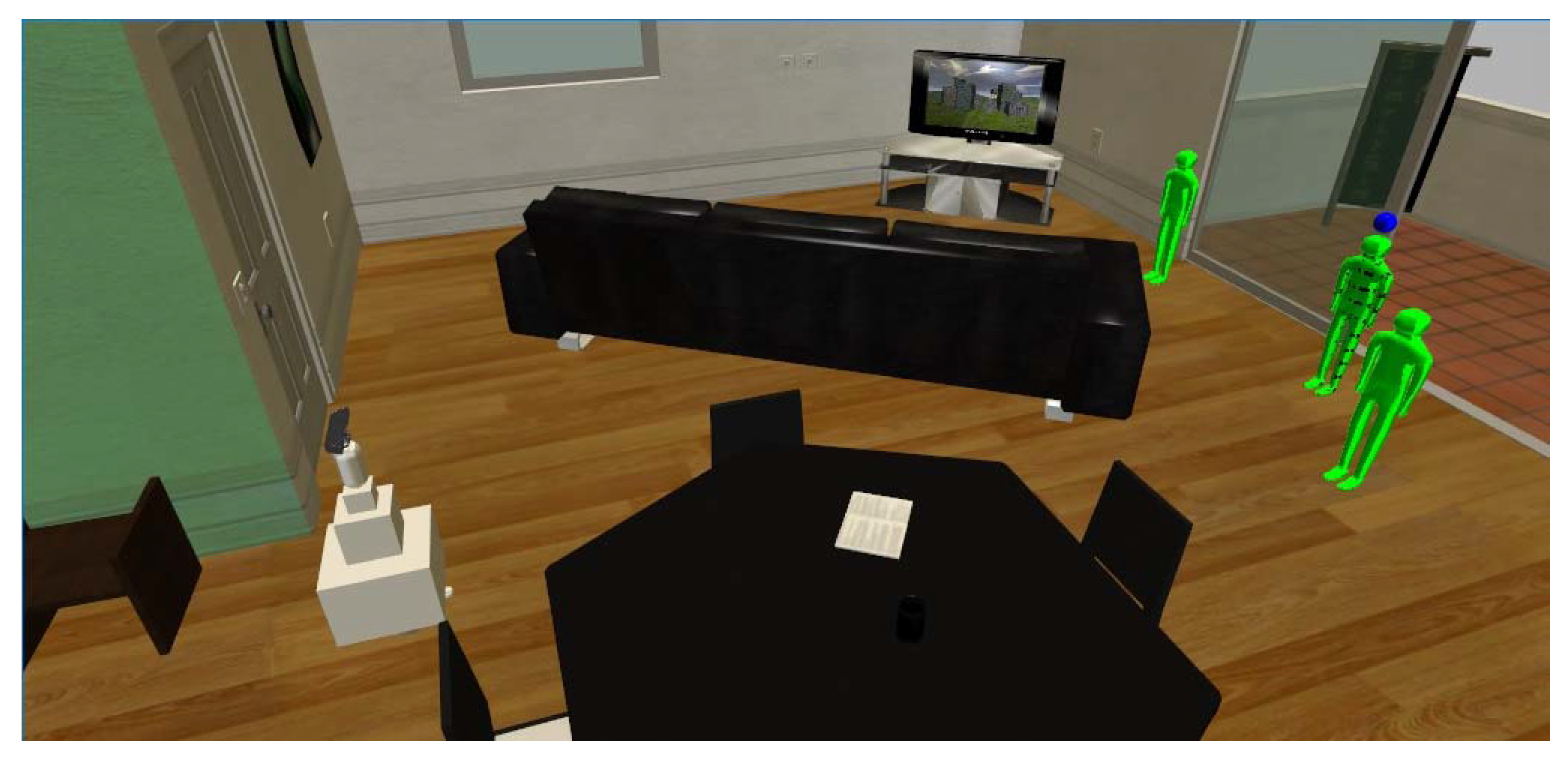
Figure 8 shows an example of a simulated environment which is complete with obstructions, CARMI, the primary subject and two decoy child entities.
The apartment scenario is adapted directly from the sample material provided by the simulation software, called the Visual Simulation Environment (VSE). This tool provides a unified environment for rapid development of test scenarios and a physics-enabled runtime to apply them. All the navigation system services are unit tested using this tool, so the constructed entities, including CARMI, Child, Decoys and obstruction objects, can be reused in the process of creating the navigation testing scenarios.
The goal of the navigation model is to enable CARMI to pick a side (when meeting an obstruction while following a child) that will result in the least amount of effort needed for human following. This means selecting a route that is a combination of the shortest path and one that will have the least number of future obstacles to contend with.
Figure 9 shows the collection of seven scenarios for operational testing and calibration of the navigation system’s weights. These scenarios emulate the typical variation of immediate environmental configurations that CARMI can expect to engage when obstructed in the ‘approach’ state.
The baseline scenario is used as a ‘clear’ situation, where the ‘approach’ state is carried out without meeting any furniture. The next six sets are split between a uniform and non-uniform obstacle. The uniform obstacle represents a blockage that does not present a significant difference in pathfinding effort, whichever side CARMI chooses. However, the system’s decision may be affected by the number, position and distance of scattered objects and/or child entities. These situations are emulated in the leftward and rightward scatter versions of the uniform obstacle scenario. The predominant parameters are going to be the mid-range depth map and the subject position.
The next three scenarios are similarly designed, but with a non-uniform central obstruction. This object closely resembles most living room furniture, such as sofas, tables, benches, and appliances. In those cases, the limited field of view (FOV) of the tracking system will not be able to determine a side that presents an obvious preferred route. The pathfinding decision will have to be made by considering the input from all three sources (perimeter, mid-range depth and subject position). The application and simulation results are presented and explored in the following section.
5. Results and Discussion
The primary unit function of the navigation system is to decide whether the robot should begin obstacle maneuvers from the left or right side of the obstruction by considering weighted inputs from the immediate proximity, mid-range depth landscape and the relative position of the primary target. As such, the initial effectiveness of the implemented system was examined by creating a set of scenarios that present the myriad of conditions that induce each path decision. The functional test consisted of six scenarios: three ranged configurations for both uniform and non-uniform obstruction encounters. The sensor input weights were adjusted by configuring the calibration constants in the state machine service to accommodate the conditions of the current environment. It was anticipated that if the navigation system consistently makes the correct path decisions, prolonged operation will result in shorter travel and least-impeded paths for indoor companion robot human-following.
To measure the system’s performance, each scenario sample was logged for elapsed runtime, VSE world coordinates for each entity, as well as the contents for both left/right tendency arrays and the ‘PathDecider’ service’s decision result. This logging feature was implemented as part of the ‘StateMachine’ service, so the period of 1 s between each log was set to account for inter-service messaging delays. To enable observation of the ‘PathDecider’ service’s performance, a plot digitizer was used to approximate the robot entity’s total travel distance vs the alternate route for it to establish unobstructed Line of Sight (LOS) to the Child entity. While each scenario was sampled for an average of five runtimes, a single performance dataset is presented to aid discussion.
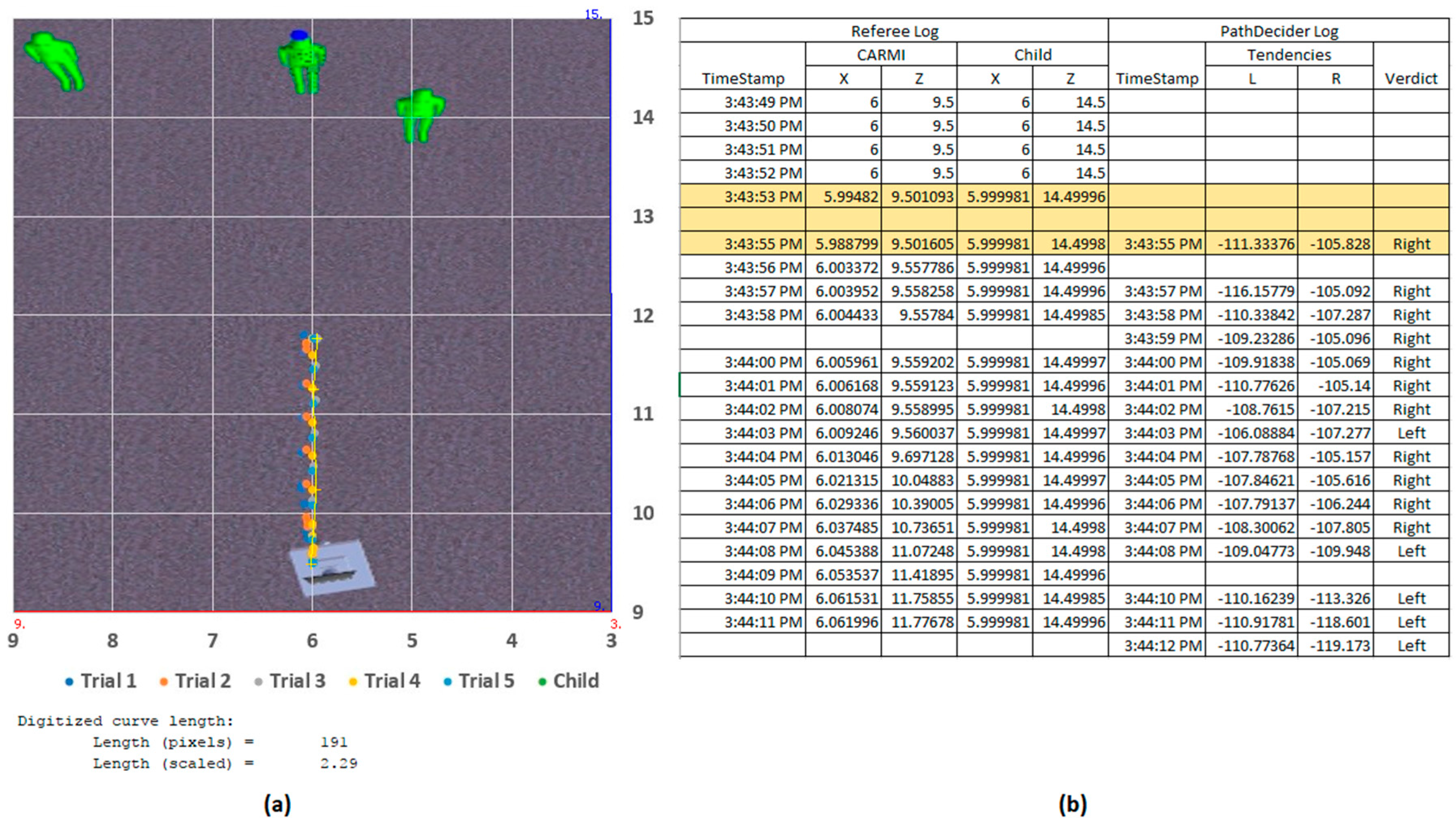
The baseline scenario was the test environment used during development and unit testing of the subject locking functionality of the navigation system (
Figure 9). It included only the CARMI entity and the three child entities (the primary target is designated by a blue ball above its head). The results were presented graphically, with the diagram axis unit in meters (m) and an approximate overhead screenshot of the simulated environment superimposed as the background. As observed in
Figure 10, all five trial runs show CARMI travelling straight for the primary Child, stopping about 2 m from the target. This shows the successful ‘subject locking’ and ‘approach’ state behaviour to maintain the target within the depth camera’s 2–3 m optimal tracking zone. At the beginning of the run, the ‘StateMachine’, ‘SubjectLocking’ and ‘PathDecider’ services boot up within 5 s, before entering the ‘scan’ state and rotate itself to scan the room for the active IR marker and a matching body (via the body tracking suite). Once acquired, CARMI switches to the ’subject-locked’ state and triggers the activation of the secondary state machine loop. Body information from the tracking suite provides the distance estimation between the target and the robot. Since the CARMI entity is spawned about 5 m away from the target child, the secondary loop switches to the ‘approach’ state which aligns the robot body to its head, then moves closer until the child is within 2–3 m away. With no obstructions in the way, the ‘approach’ state commences until the target is within the intended range, before switching to the ‘idle’ state (during which the robot’s head continuously centre on the target while the body rotates to align itself with the head). The total runtime for one selected sample is 22 s, including initial cold boot (completion stage timestamps are highlighted in the logs shown in
Figure 10).
5.1. Uniform Obstruction Tests
The first round of tests involved a uniform block obstruction between CARMI and the child entities (
Figure 10). With the absence of any other obstructions in the vicinity, it was predicted that the robot would select both routes equally. However, the results showed that in all five runs, CARMI chose to navigate around the block from the left-hand side. At the beginning of each run, CARMI starts off the same way as it did during the baseline scenario. During the ‘approach’ state, it encountered the uniform block, which triggered the switch to the ‘pathfinding’ state (as highlighted in the log shown in
Figure 11). At this stage, the robot evaluated the immediate vicinity (via perimeter proximity), mid-range landscape (via depth map) and the relative direction of the target position to populate the tendency arrays. A uniform block is registered by the proximity array as equal tendencies for both sides, which prompted the earlier prediction. However, the depth component indicated a slightly leftward-bias, because the rightmost decoy child was spawned somewhat nearer to the robot than the others. The highlighted timestamps in the sample log show a much higher repulsion tendency from the right-sided array, thus influencing the ‘PathDecider’ to favour the ‘left’-ward verdict. The total response time from the fusion operation and decision-making to the initial course correction actuation was 2 s.
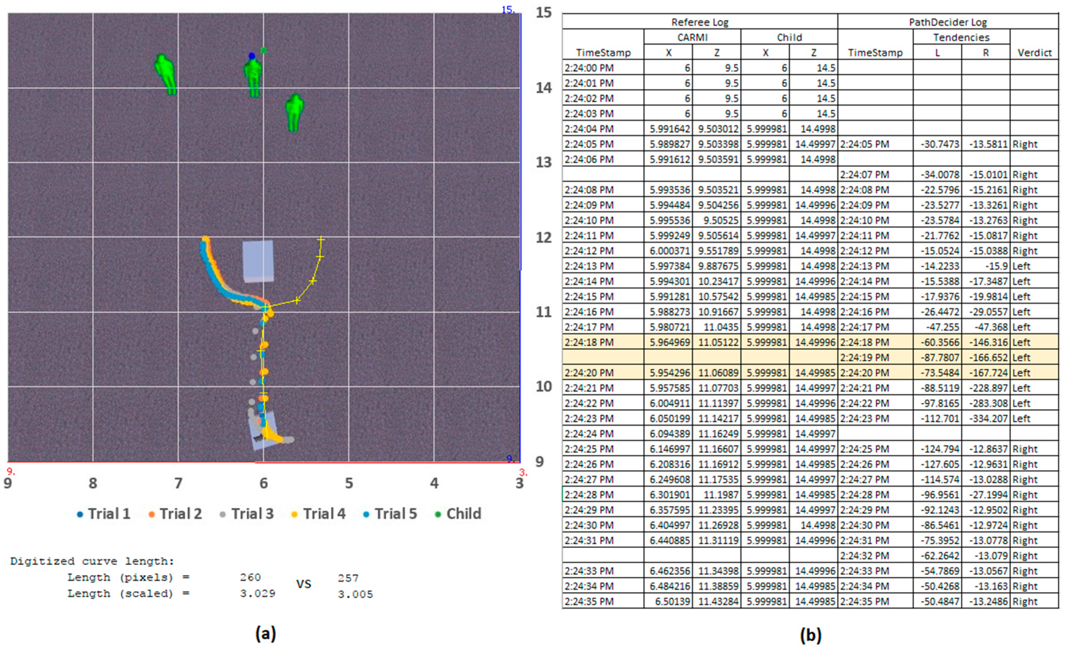
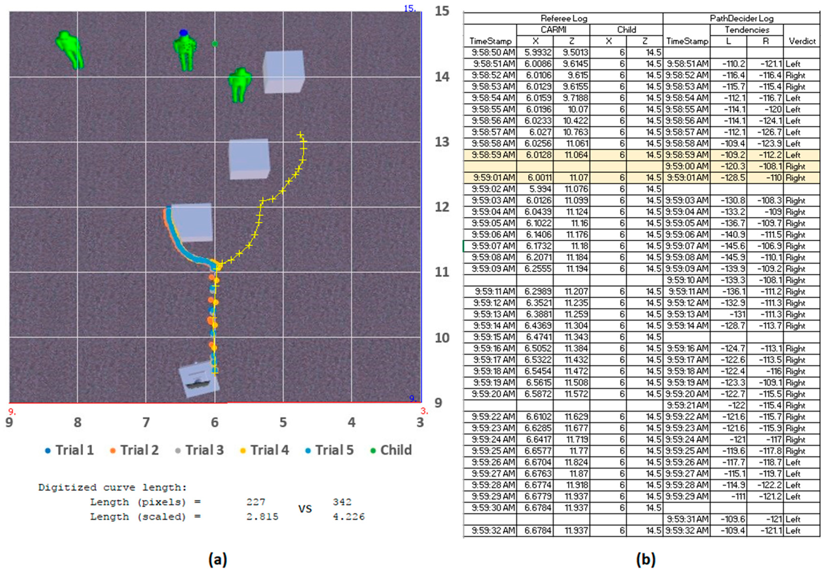
The following two variations of the uniform-obstruction scenario feature additional mid-range blocks scattered leftwards (
Figure 12) and rightwards (
Figure 13), respectively. In the leftwards-scatter scenario, CARMI has opted for the right-side route for all five runs. The depth component indicated increased mass of obstructions on the left-half of the FOV (displayed sample shows Left-Right tendencies of −126.899 vs. −110.434), which was enough to surpass the closer proximity of the front-most decoy child. The total travel distance of the robot, in this case, was 3.234 m vs. 4.185 m if the left-side route was taken instead.
In the rightwards-scatter scenario, the additional blocks served to increase the mass on the right-half of the FOV, thus reinforcing CARMI’s decision to go to the left-hand side (−109.2 vs. −112.2). This sample’s robot travelled 2.815 m vs. 4.226 m if the alternate route was taken. In both leftward and rightward scatter scenarios, the navigation system helped guide the entity towards a side with a shorter route.
It was noted that CARMI’s motion halted right after maneuvering past the main obstruction at elapsed times of 39 and 42 s. That was because the target child was within the 2–3 m detection zone with direct LOS, so CARMI switched into its ‘idle’ state.
5.2. Non-Uniform Obstruction Tests
The next set of scenarios were developed to resemble most of the furniture and larger objects commonly found in typical indoor environments. Benches, sofas, dining tables and shelves often come in inconsistent dimensions, which could exceed the breadth of the tracking system’s combined view. In these situations, the navigation system assumes that both ends of a particularly long obstruction cannot be gauged and will instead channel more weight on the mid-range depth landscape and relative position of the target child when deciding on which direction to take. However, if the proximity array indicates that one edge of the obstruction is in view, CARMI will favour that side unless the other two arrays present significant repulsion.
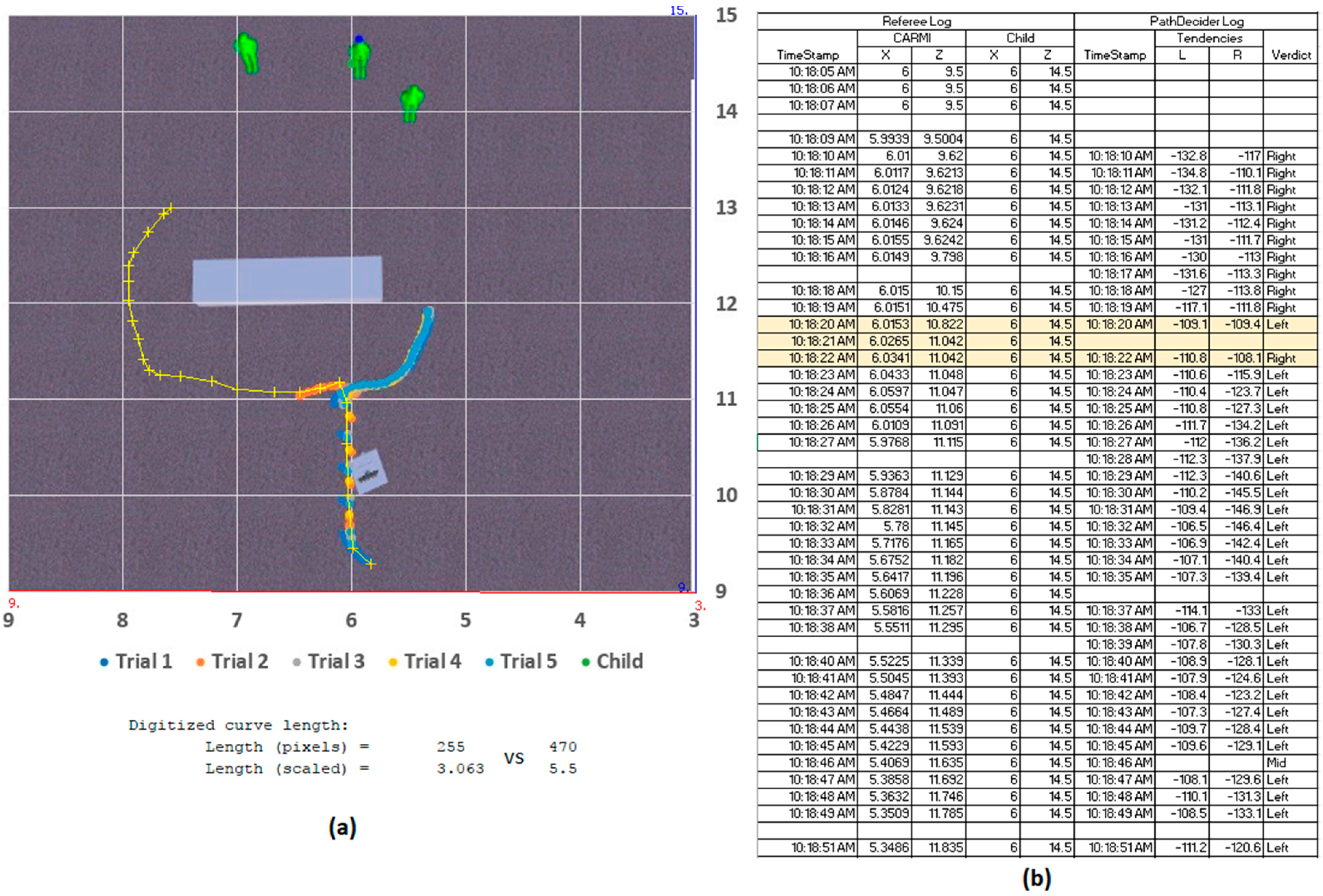
This behavior was observed in the first non-uniform obstruction scenario (
Figure 14), where one in five trial runs resulted in a leftward deviation that led to a longer way around the object. It was likely that the proximity of the front-most decoy contributed to the momentary tendency switch for that run. But, as observed in the remaining tests, CARMI preferred the right-side route, since that edge of the obstruction was within the navigation system’s FOV. This sample logs, however, indicated that the tendency difference between both sides is almost indiscernible (−109.1 vs. −109.4 for leftward and rightward arrays respectively). While the validity of the leftward route could not be conclusively evaluated, due to the limited FOV, a poorly-made choice in this case results in a far longer travel distance of 5.5 m vs. the rightward 3.063 m path.
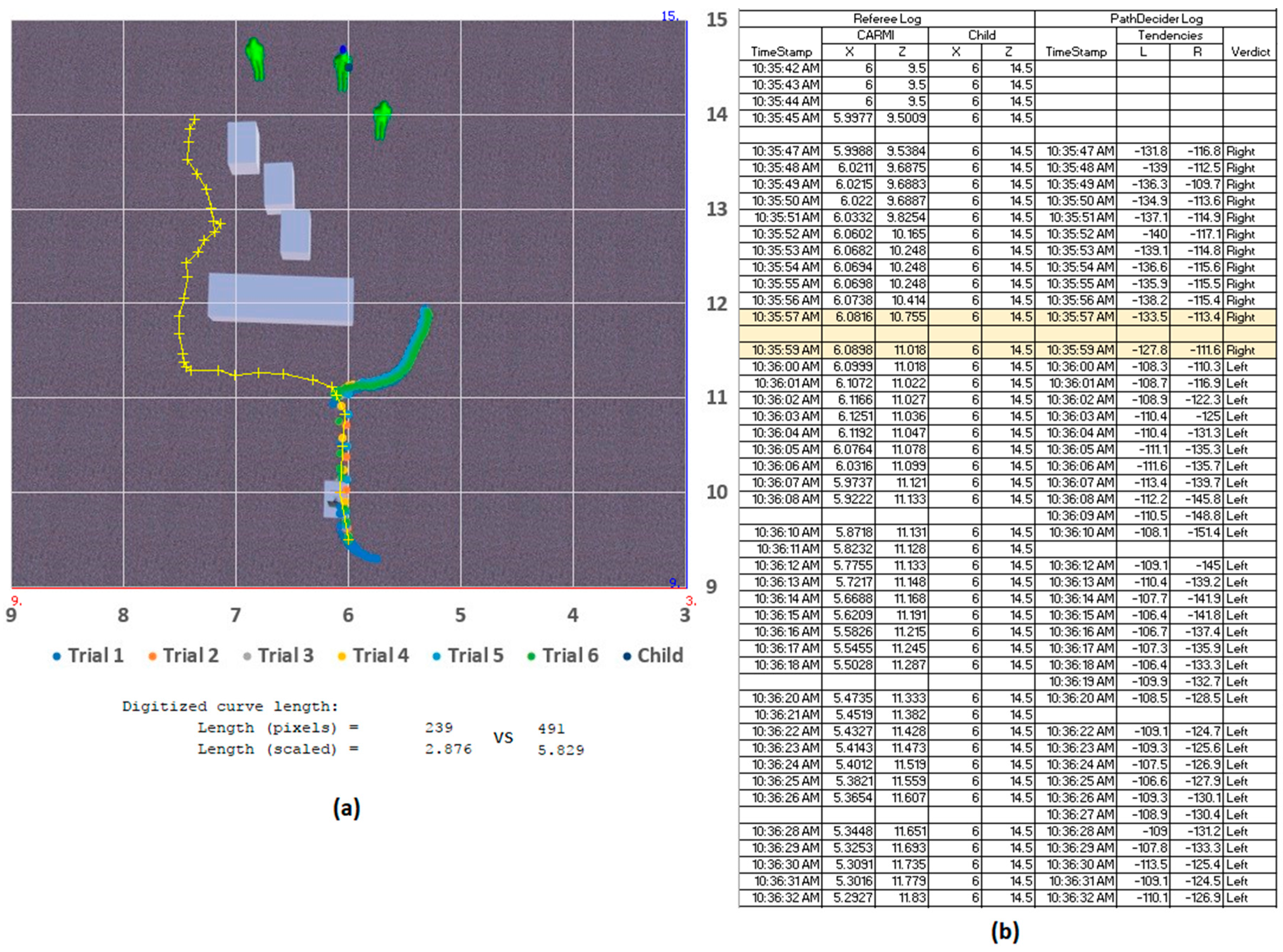
The next scenario included several additional blocks scattered to the left of the mid-range landscape (
Figure 15). This time, the following runs revealed a consistent tendency towards the right, demonstrating overall influence from the depth and proximity arrays. The selected sample log shows the contents of the tendency arrays: −133.5 vs. −113.4, resulting in a confident rightward verdict by the ‘PathDecider’. The selected path travel distance was 2.876 m vs. 5.829 m if the alternate was taken.
The third non-uniform obstruction scenario had a rightwards cluster of objects that were further displaced compared to the previous one (
Figure 16). Since the ‘pathfinding’ state only came into effect when CARMI was already near the bar, it had to consider an indeterminate length of obstruction to the left, as well as the multitude of mid-range depth objects on the right. One in five runs experienced a malfunction in the DSS messaging queue, but the remaining four attempts showed CARMI preferring to attempt a maneuver from the indeterminate-length left side. The sample logs in the figure show a clear consideration of the mid-range depth landscape, identified by the contents of the left-right tendency arrays (−155.8 vs. −108.2). This result is influenced by the mass of mid-range depth objects and the higher weight assigned to the depth array, which was adjusted for this environment. The higher priority for the depth component could have superseded both the perimeter and target position arrays in determining the output tendency of the algorithm (strong rightwards verdict). This scenario was especially lengthy, due to the increased travel distance for both routes (6.069 m vs. 6.756 m). Note that the ‘PathDecider’ consistently evaluates the best general direction towards the goal, even outside of the ‘pathfinding’ state.
Throughout the simulation exercises of the seven scenarios, the average execution time for processing the tendency arrays, deciding on which direction to take, and initiating the choice of obstacle maneuvers was 2 s. This result was due to the messaging compartmentalization of MRDS, so there is still computational headroom improvement possible for shortening this response time.
Table 1 shows the extracted total travel distances and elapsed time for each selected sample. It was concluded that the average speed of the simulated robot is 0.07 m/s. This system speed is subjected to the runtime characteristics of the VSE, and will vary depending on the form and build of the physical implementation. However, the limited average entity speed can be considered appropriate for reducing the risk of unforeseen collisions and inadvertent breach of comfortable approach zones [
6].
The travel distances from both recorded and projected alternate paths are shown in
Table 2. Each sample’s distance difference is used to calculate the improvements against the alternate path. It is shown that the CARMI navigation system’s implementation of the pathfinding phase is capable of selecting a direction around obstacles that are 26.743% shorter than the other.
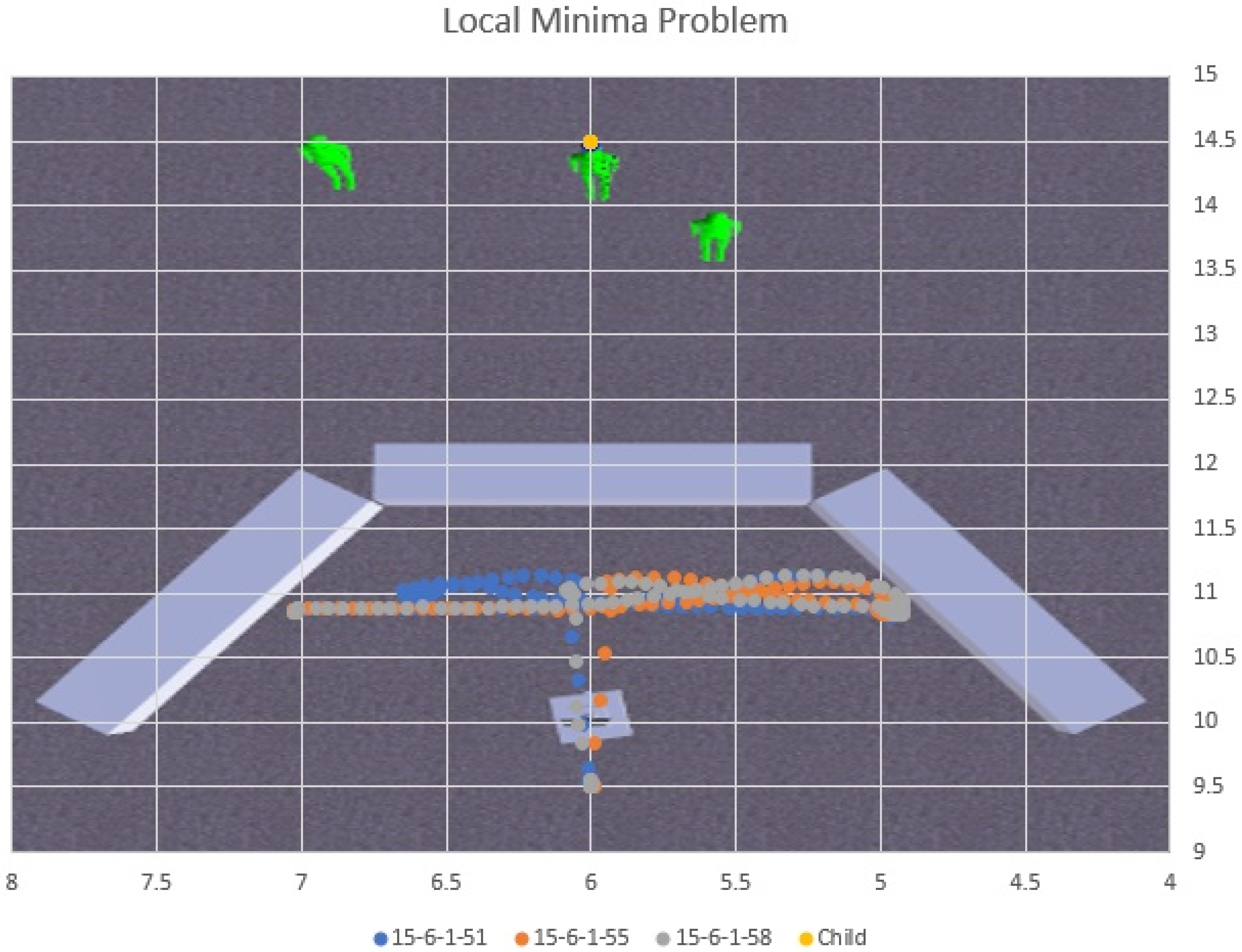
During the process of incremental design and development, it was determined that an additional condition should be incorporated into the navigational behavior, to trigger a reset of the state machine, should CARMI’s body and head be rotated more than 120° between them, indicating that the maneuver was heading further away from the primary target. In such a situation, the robot realigns its body with the head (which is still locked on the subject), then proceed to approach and reinitiate the pathfinding phase to reconsider the maneuver. However, incorporation of this behavior component also introduced a possible error condition in which the robot may find itself isolated in a local minimum. A scenario was constructed to simulate this outcome and it was confirmed (
Figure 17), but its occurrence can be minimized by thoughtful arrangement of furniture and diligent treatment of clutter in the living environment.
This implementation of the navigation model for CARMI has shown that it can successfully evaluate the environment for an initial direction to begin obstacle-avoidance maneuvers during human-following. This was achieved without prior mapping of the environment nor the use of mapping sensor solutions, mimicking how humans decide to navigate around buildings in an unfamiliar area while relying only on line-of-sight and a general heading for the destination.
The test results have proven that the navigation system achieved the goal of minimizing robot motion by considering the target position, as well as short-range and mid-range depth profiles for advising a path of least resistance (one which will lead the robot closer to the target but through a path that has the least number of future obstacles to mitigate). The test results only showed the initial path decision making, so longer term performance will only be observable in more extensive scenario layouts, using a manually piloted child entity.
6. Conclusions and Future Work
To recap, indoor navigation poses a significant challenge to human-following companion robots. This is complicated further when the robot can only rely on onboard sensory hardware with no support from embedded environments or mapping and learning facilities. This research aimed to provide a solution that combines readily available sensors with a fusion algorithm to make stand-alone indoor navigation possible. This was achieved using a commercially available depth camera, an array of proximity sensors and an IR Active Marker.
The navigation system was first designed and developed for the use of CARMI, a companion avatar robot for the mitigation of injuries. CARMI’s injury prevention strategy relies on the use of a Kinect device, which requires the robot to constantly reposition its sensor suite head to ensure that the target child is within the optimal tracking zone. Thus, the robot is virtually leashed using combined wearable and vision-based tracking, distilled into a navigation model. This navigation model is then implemented using Microsoft Robotics Developer Studio (MRDS) and tested using its Visual Simulation Environment (VSE). The core system consists of two parallel state machines, implemented as a set of MRDS services, that interwork with each other during runtime. A virtual CARMI entity associated with this navigation system is added into VSE scenarios along other entities such as the primary target, decoys and obstructions for simulations. An initial test set of seven scenarios were created and simulations were run to confirm the navigation system’s behaviour and operability. The results showed that its base functionality for subject locking, selecting a direction for pathfinding and the resulting obstacle-avoidance maneuver had been performed successfully.
Current observations of the system have revealed several shortcomings and possible avenues for improvements. One major cause for concern is the linear solution for transforming the coordinate system between the AIRMT view-space to the depth camera’s. Image frame displacement and orientation of multiple cameras and different hardware present complex problems, which are subjects of extensive research related to stereoscopic machine vision and multi-sensor fusion. While the current method can produce rough estimations of transformed marker coordinates in the depth camera FOV, the lack of resolution becomes exponentially severe as the distance of the subject increases. This does not present a critical problem for the CARMI implementation because the depth camera limitations dictate a 2–3 m tracking zone, but it may impede other future systems that employ alternative body tracking systems.
Another point of weakness in the current implementation is the omission of the top and bottom trim for the depth map during the pathfinding phase. These were incorporated into the algorithm during the navigation system modelling process to account for ignoring depth profiles that were physically suspended and do not present themselves as obstructions, as well as short-range objects that would already have been accounted for by the perimeter array. This will be slated for inclusion in the next update to the MRDS CARMI navigation system.
The local minima problem was also encountered and studied in an related work involving the use of waypoints for robot navigation [
32]. This work suggested a solution that incorporates a basic memory map of previously travelled locations. Applied to this problem, the navigation system can record a waypoint at the first instance of aborted ‘pathfinding’. Because there is no form of overall mapping available, the system can use dead reckoning as a means of tracking a previously-set waypoint. If another abortion occurs, then the robot can be guided back to the waypoint where it can execute an extended ‘pathfinding’ event without the abortion condition. This solution can be explored in a future work.
The navigation system depends on multi-sensor fusion to get a snapshot of the immediate environment and react at each encounter of an obstruction. No prior data is stored, so navigation is essentially handled as a static closed-loop control system. This means that a properly calibrated CARMI can operate as intended if the environmental and operational conditions do not change. An alteration to the room lighting, or erratic child behaviour (such as a sudden change in activity intensity) could result in sub-optimal tracking and human-following performance. An actual living space is a dynamic environment and thus a machine learning mechanism will need to be employed so that the navigation system can autonomously adjust its calibration constants over time.
The test scenarios documented in this paper only involves a static child entity to represent the Primary Subject because the intent is to examine the reliability of the ‘subject locking’ and ‘pathfinding’ state handling of the navigation system. Subsequent scenarios will consist of more elaborate obstacle courses and a manually controlled child entity to simulate a dynamic human-following challenge.
Real-time autonomous robot operation characteristics are subjective to their respective application fields, with system response times ranging from 12 ms to half a minute [
33,
34,
35]. With a response time of 2 s, this standalone system demonstrated a possibility of real-time indoor human-following, without the use of simultaneous localization and mapping (SLAM) solutions, distributed computing or embedded environments. The navigation model makes its decisions by evaluating only the most updated dataset from the sensors, so the robot reacts to the current situation, based on what is perceived in its perimeter, mid-range landscape and general direction of its target. Thus, the navigation system is ideal for environments that are dynamic and populated with a variety of uniform and non-uniform obstructions, which characterizes most domestic living rooms.
Kinect and similar devices are relied upon for a majority of vision-based autonomous activity monitoring, but are impeded by optical occlusions, dynamic lighting conditions and more. This navigation system’s sensor fusion between the depth camera and active IR marker tracking creates a redundancy check that reinforces against loss of visibility and inconsistent tracking that are experienced by most motion capture equipment.
Most navigation system research rely on the use of light detection and ranging (LiDAR) sensors, radio frequency localization and learning algorithms to map environments for calculating the shortest paths. Even the Potential Field Method (PFM), that inspired this research’s model, relies on a 2D snapshot of the area for processing. This research presents a homogenous framework that is compatible with generic ranging sensors, depth cameras and RGB cameras, thus enabling the implementation of low-cost companion robots that do not impose any environmental modification or additional hardware on the part of their users.
In conclusion, this research has designed and implemented the sensor fusion-based human-following robot navigation system, along with simulation results, to prove its successful functionality. This outcome greenlighted more extensive testing scenarios as well as laid the roadmap for future improvements to expand this system’s applicability.
