Article

Bin-Dog: A Robotic Platform for Bin Management in Orchards

1
Center for Precision & Automated Agricultural Systems, Washington State University, Prosser, WA 99350, USA
2
School of Electrical Engineering & Computer Science, Washington State University, Pullman, WA 99163, USA
3
School of Mechanical, Industrial & Manufacturing Engineering, Oregon State University, Corvallis, OR 97331, USA
*
Author to whom correspondence should be addressed.
Robotics 2017, 6(2), 12; https://doi.org/10.3390/robotics6020012
Submission received: 1 April 2017 / Revised: 10 May 2017 / Accepted: 18 May 2017 / Published: 22 May 2017
(This article belongs to the Special Issue Agriculture Robotics)

Abstract

:
Bin management during apple harvest season is an important activity for orchards. Typically, empty and full bins are handled by tractor-mounted forklifts or bin trailers in two separate trips. In order to simplify this work process and improve work efficiency of bin management, the concept of a robotic bin-dog system is proposed in this study. This system is designed with a “go-over-the-bin” feature, which allows it to drive over bins between tree rows and complete the above process in one trip. To validate this system concept, a prototype and its control and navigation system were designed and built. Field tests were conducted in a commercial orchard to validate its key functionalities in three tasks including headland turning, straight-line tracking between tree rows, and “go-over-the-bin.” Tests of the headland turning showed that bin-dog followed a predefined path to align with an alleyway with lateral and orientation errors of 0.02 m and 1.5°. Tests of straight-line tracking showed that bin-dog could successfully track the alleyway centerline at speeds up to 1.00 m·s−1 with a RMSE offset of 0.07 m. The navigation system also successfully guided the bin-dog to complete the task of go-over-the-bin at a speed of 0.60 m·s−1. The successful validation tests proved that the prototype can achieve all desired functionality.

1. Introduction

Bin management is an important orchard operation during apple harvesting. Typically, bins capable of carrying 400 kg of fruit are widely used in the Pacific Northwest region of U.S. for apple storage and transportation. As the average apple yields for fresh market in Washington State from 2008 to 2013 was about 2.9 billion kg [1], roughly 7.2 million bins needed to be handled in orchards every year. The conventional bin management process is completed by tractor-mounted forklifts or bin trailers maneuvered by a tractor driver. The entire bin management process in orchards includes empty bin placement and full bin removal. Initially, empty bins are placed at estimated locations between tree rows by tractor drivers before harvest. During harvest, pickers pick fruits and load the picked fruits into nearby bins. Once a bin is filled, the drivers must come and remove the full bin from the harvesting zone and transfer it to a collection station. Finally, they return and place an empty bin in the harvesting zone. Bin management with tractors is labor-intensive, which requires tractor drivers to keep tracking the status of the bins and frequently enter alleyways to perform bin handling tasks through the entire harvesting process. Effective and efficient production is becoming a greater challenge to the tree fruit industry in the U.S. due to its heavy use of labor during the harvest season. Furthermore, labor shortages threaten the viability of the tree fruit industry in the long term [2]. Innovation is critical to overcoming this problem and maintaining the industry’s competitiveness in the global marketplace.
Over the past few decades, numerous utility platforms have been developed to improve the productivity of orchard operations [3,4,5,6]. Most of these platforms still rely on human operators to maneuver for orchard traversing. Autonomous vehicles have long been a solution used to ease the pressure of labor issues on agricultural activities. Due to the development of computing units and sensor technologies and efforts from numerous researchers, Global Positioning Systems (GPS) and vision-guided vehicles have been widely implemented on farming equipment [7,8,9,10]. Current high-end commercial GPS-based navigation systems can reduce the path tracking error to less than 0.03 m [11], which is reported to be superior to manually-steered system in terms of driving accuracy [12]. Despite its extensive applications in farming, autonomous platforms for orchard operations are still relatively rare due to unstable GPS signals in orchard environments [13]. Alternative perception sensors to GPS for orchard navigation are local sensors such as laser scanner and vision sensors. Due to the relatively high accuracy and invariance, laser scanners have been widely applied to measure tree canopy geometry [14,15,16,17,18] and map orchards [19]. Furthermore, in modern high-density orchards, fruit trees are planted in straight rows, which makes it ideal to use local sensors to guide robotic platforms operating in such environments. Barawid et al. [20] used a 2D laser scanner to guide a tractor to follow the centerline of tree alleyways in an orchard. An autonomous navigation system developed by Subramanian and Burks [21] used multiple sensors including a laser scanner, a video camera, and an inertial measurement unit (IMU) to guide a vehicle in a citrus orchard. It can drive along tree alleyways with a mean lateral error of 0.05 m at a speed of 3.1 m·s−1 and steer into the next alleyway at the end of rows. Hamner et al. [22,23] developed an automated platform guided via two 2D-laser scanners, which has already completed over 350 km for orchard traversals [24]. Moorehead et al. [25] presented a multi-tractor system for mowing and spraying in a citrus orchard. Each autonomous tractor in the system used a 2D-laser and a color camera for environment perception. These tractors have successfully driven more than 1500 km. Systems developed in previous studies are mainly used as assist platforms that can carry or follow workers and traverse tree alleyways. These studies focus on relatively simple driving tasks such as straight line driving between tree rows and row entry.
Despite all the developed technologies for orchard operations, currently, no robotic platforms for bin management are commercially available. Our long-term goal is to develop a robust multi-robotic bin management system implementable in the natural environment of tree fruit orchards. This article focuses on the development of a novel bin-dog system capable of robotic bin management. The entire system includes two major components: (1) A bin-dog prototype that can deliver an empty bin and remove a full bin from an alleyway in one trip, and (2) A control and navigation system to assist the bin-dog to complete bin-managing tasks automatically inside an orchard.

2. Material & Methods

2.1. Design of the Bin-Dog Prototype

To test the proposed concept, it is essential to design a research prototype of the bin-dog robot capable of handling bins in a natural orchard environment. Such a prototype should perform the critical functions of (1) carrying a 1.20 m × 1.20 m × 1.00 m fruit bin and traveling at a 1.2 m·s−1 maximum speed within a 2.40 m tree alleyway in typical Pacific Northwest (PNW) high-density tree fruit orchards; (2) carrying an empty bin to go over a full bin laid in alleyway, and placing an empty bin at a target location in the harvesting zone; and (3) driving a full bin, weighing up to 400 kg, back from the harvesting zone to the designated bin collecting area outside the alleyway, all in one trip. To do so, the bin-dog prototype uses a “go-over-the-bin” function, which allows it to drive over a full bin between tree rows.
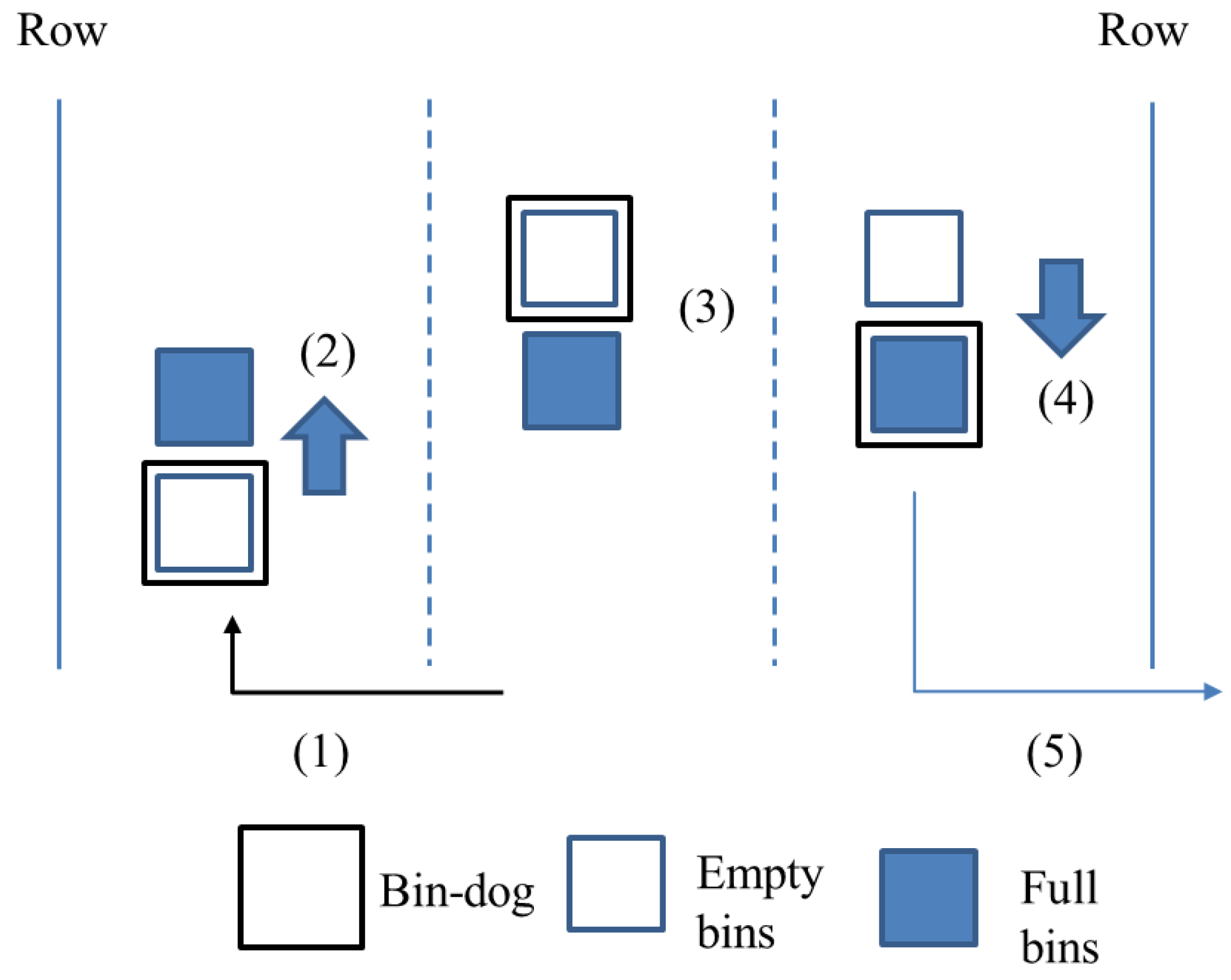
As illustrated in Figure 1, the system manages bins in a five-step process. It can (1) load an empty bin in the collection station and drive it into an alleyway until reaching the full bin, (2) lift the empty bin and drive over the full bin, (3) continue to the target spot and place the empty bin, (4) drive back to load the full bin, and (5) drive the loaded full bin out of the alleyway to the collection station. By combining two trips into one, such a process has the potential to greatly reduce the travel distance and time, significantly improving overall efficiency.
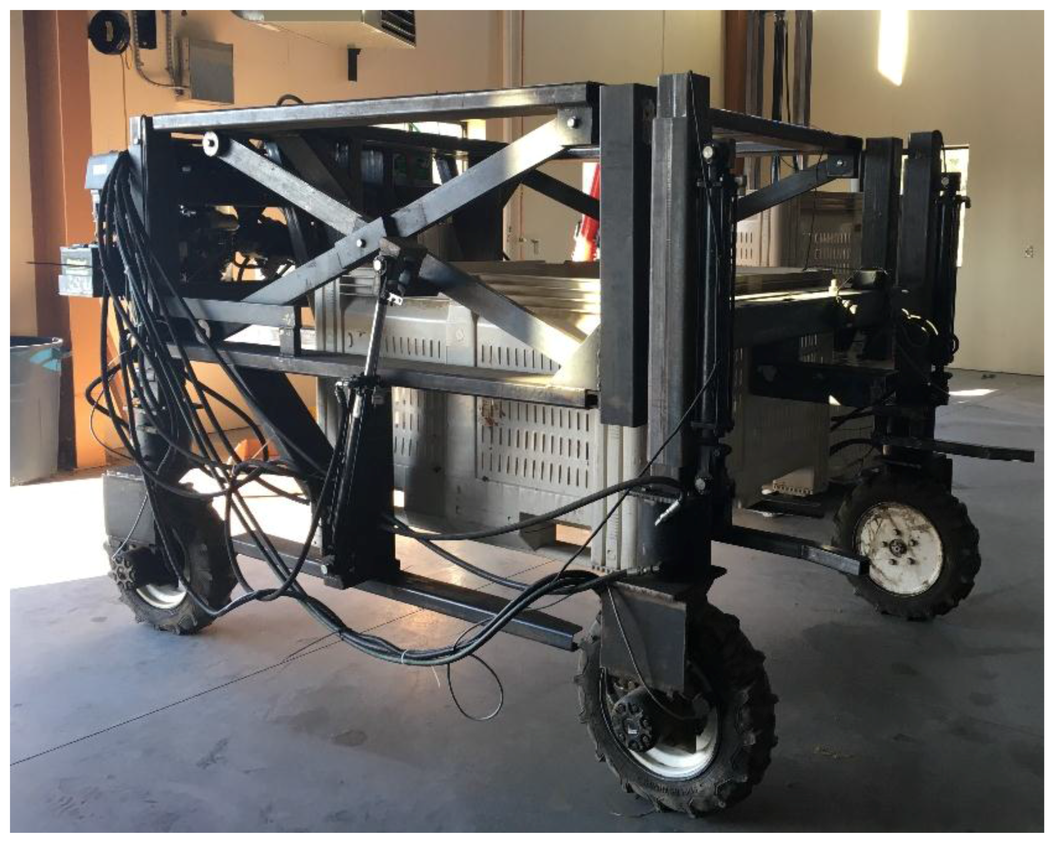
To validate the concept and usability of the proposed bin-dog system in a natural orchard environment, a research prototype (Figure 2) is designed and fabricated [26].
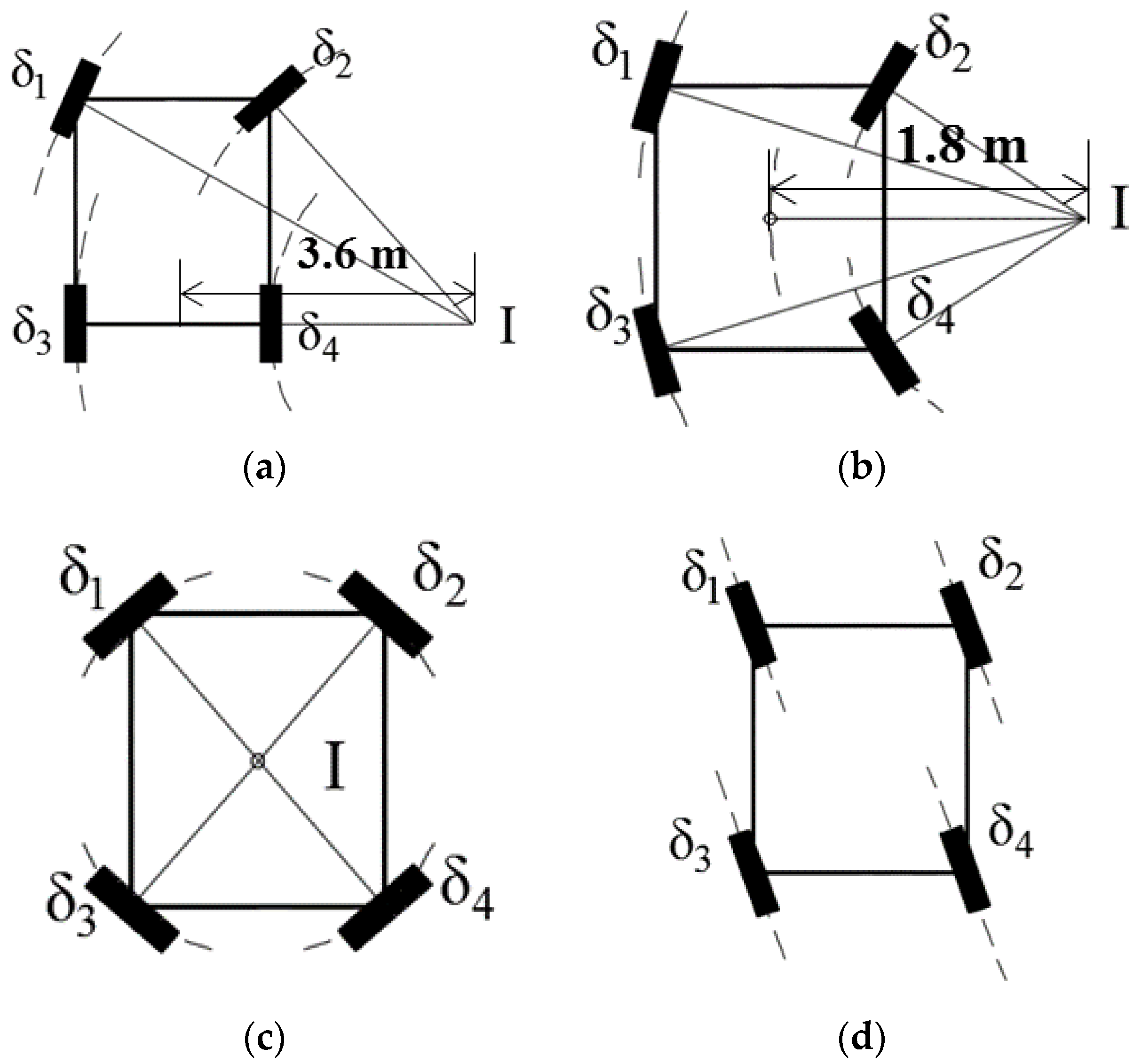
This research prototype is built with two main components: the driving and steering system, and the bin-loading system. A hydraulic system is used to actuate both systems. The hydraulic system is powered using a 9.7 kW gas engine (LF188F-BDQ, LIFAN Power, Chongqing, China) and operated under a pressure of 10.3 MPa. The research prototype uses a four-wheel-independent-steering (4WIS) system to obtain the effective and accurate maneuverability needed to guide the platform in the confined space of a natural orchard environment. It uses four low-speed high-torque hydraulic motors (TL series, Parker Hannifin, Cleveland, OH, USA) and four hydraulic rotary actuators (L10-9.5, HELAC, Enumclaw, WA, USA), which are controlled by eight bidirectional proportional hydraulic valves (Series VPL, Parker Hannifin, Cleveland, OH, USA) to achieve such a steering system. Four optical incremental encoders (TR2 TRU-TRAC, Encoder Products Company, Sagle, ID, USA) are used to measure the rotational speeds of each wheel, and the steering angles are measured by four absolute encoders (TRD-NA720NWD, Koyo Electronics Industries Co. LTD, Tokyo, Japan). To obtain the most effective maneuverability within the confined working space of an orchard, the bin-dog uses four common steering modes: Ackermann steering, front-and-rear-steering (FRS), spinning, and crab steering, as illustrated in Figure 3. To avoid excessive mechanical stress caused by large steering angles, the minimum turning radius of the Ackermann steering and the FRS are set at 1.8 m and 3.6 m respectively. The maximum vehicle speed (both forward and backward) is up to 1.2 m·s−1, and the maximum steering speed of a wheel is 30°·s−1.
The prototype uses a forklift-type bin loading system, operated by a hydraulically actuated scissors-structured lifting mechanism, to gain effective and reliable operation. Based on this design, two cylinders (HTR 2016, Hercules, Clearwater, FL, USA) are symmetrically installed on both sides of the scissors structure, and a flow divider (YGCBXANAI, Sun Hydraulics, Sarasota, FL, USA) is used to ensure the two cylinders extended and retracted at the same pace to ensure smooth bin-loading motion. The actions of the cylinders are controlled using a solenoid operated directional control valve (SWH series, Northman Fluid Power, Glendale Heights, IL, USA). A touch switch is also installed on the fork to determine if a bin is loaded on the fork or not. A string potentiometer is installed on the hydraulic cylinder to measure the forking lift height. The bin-loading system allows the bin-dog to handle loads up to 500 kg. It takes about 7 s to lift a bin from ground to the highest position (1.5 m) and 5 s to lower it.
With all the aforementioned mechanical subsystems, basic functionalities, including driving and steering with 4WIS system, loading and unloading bins are achieved.

2.2. Control and Navigation System of the Bin-Dog

To automatically complete the designated bin-managing process described in Figure 1, the control and navigation system of the bin-dog should be able to safely navigate in a headland and between tree rows, and identify and locate fruit bins in the alleyways. As stated in the introduction, this article focuses on reporting the development of the platform for a novel bin-dog system. The control and navigation algorithms developed for maneuvering the bin-dog are distinct contributions, which are applicable to general autonomous in-orchard platforms, and have been reported in more detail in separate articles [27,28]. As a brief description, the newly-developed control and navigation system has two subsystems: a low-level control system for realizing driving and steering with 4WIS, and a multi-sensor based navigation system for localization, object detection, task scheduling and navigation in orchard. The two subsystems are briefly introduced in the following sections.

2.2.1. Low-Level Driving and Steering Control System

As illustrated by 
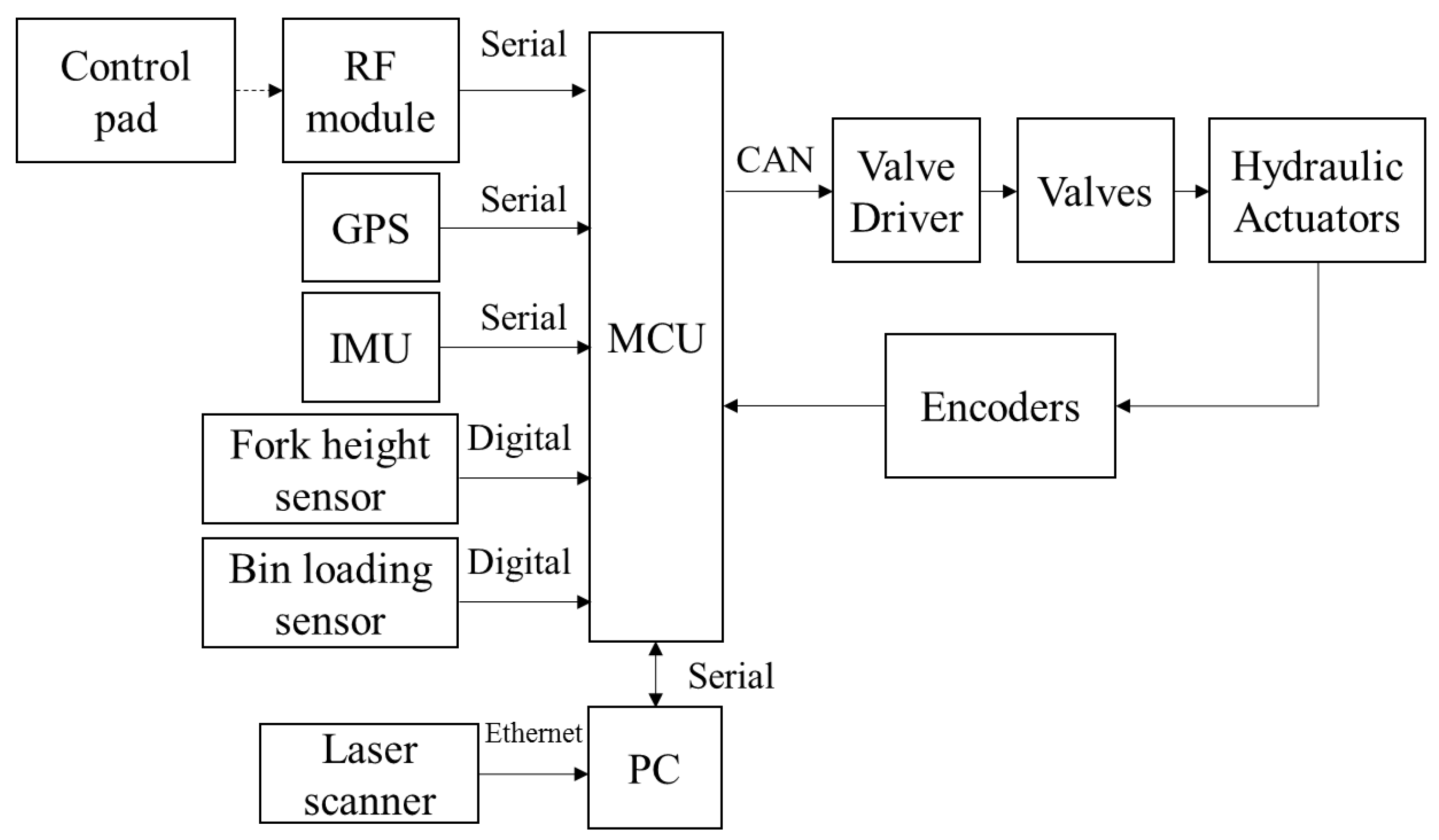
Figure 4, the low level control system are implemented in a microcontroller unit (MCU) (Arduino Mega, Arduino, Scarmagno, Italy) and responsible for the control of all the actuators on the bin-dog. The bin-dog has two work modes: automatic and manual. When it is in automatic mode, the low-level control system receives commands from the navigation system, which is implemented on a laptop. The commands include vehicle speed and angle, steering mode, and desired fork height. When it is in manual mode, the same commands are sent from a control pad through radio frequency (RF) modules. A wheel coordination module is used to calculate the desired wheel speed and angle of each wheel based on these commands. Afterward, the generated control signals are sent to a multi-channel valve driver (MC2, Parker Hannifin, Cleveland, OH, USA) through CAN bus to achieve the desired actions.

2.2.2. Navigation System

The navigation system consists of four basic modules: localization, object detection, task schedule, and navigation. The localization module determines the position of the bin-dog in open space (headland) and GPS-denied environments (tree alleyway). The object detection module allows the system to identify and locate objects, including tree rows and fruit bins. The task schedule module arranges the sequences of actions to complete different bin-managing tasks such as headland turning, straight line tracking between tree rows, and “go-over-the-bin.” The Robot Operating System (ROS) [
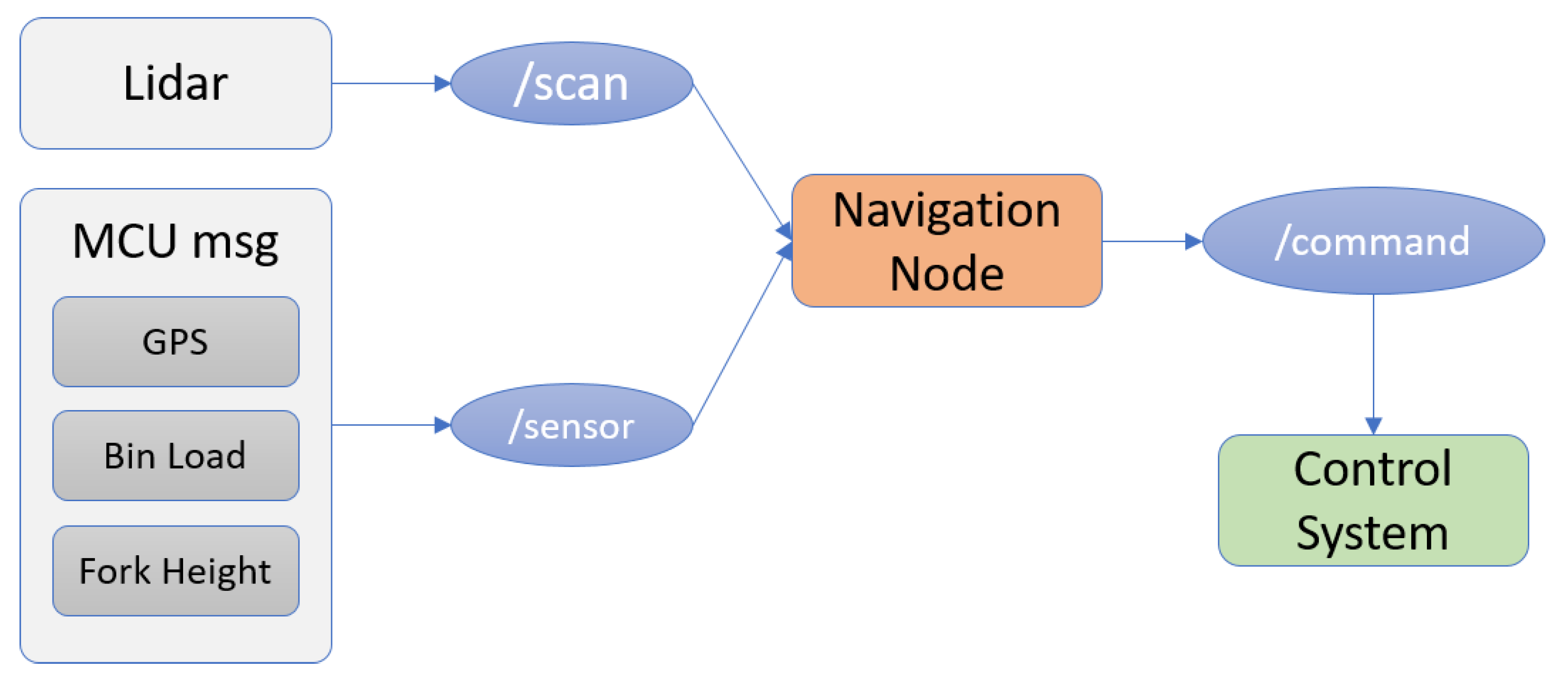
29] is used to run the main navigation program and to collect and process the sensor data. Due to difference of data type and device interface used in our system, as shown in Figure 5, we use two sensor topics—“/scan” and “/sensor” (data transmission channels in ROS) to collect perception data. Sensors, including GPS, a bin-loading sensor, and a fork height sensor, are first connected to the MCU. The sensed data are wrapped into a self-defined data format before being sent to the ROS system. The topic “/scan” reads the data from Light Detection and Ranging (LIDAR) sensors, and the topic “sensor” reads the wrapped data from the MCU. These data are further processed in the “navigation node” to generate driving-control commands. Calculated control commands from the navigation system are then passed (through a serial topic named “/command”) to the MCU used in the low-level control system. These commands are sent at a rate of 20 Hz.

2.2.3. Localization

When operating in open space, global sensors, such as GPS, can provide high-accuracy position coordinates. However, when operating between tree rows, GPS sensors could experience dropouts due to interference from the tree canopy. Therefore, in this study, a RTK GPS (AgGPS 432, Trimble, Sunnyvale, CA, USA), two laser scanners (LMS111, SICK, Waldkirch, Germany), and an inertia measurement unit (IMU) (AHARS-30, Xsens, Enschede, The Netherlands) are used as perception sensors for the bin-dog. As illustrated in Figure 6, two laser scanners are installed in the front and rear of the bin-dog, respectively. Both laser scanners are mounted at 20° angle looking 5.00 m in front of them. These laser scanners allow the bin-dog to perform navigation tasks while driving forward or backward in the alleyways. They have a sample rate of 25 Hz and their data form the point cloud used to achieve real-time perception.
Localization in headland is achieved by calculating the global position of the bin-dog and its heading angle. The RTK-GPS had sub-inch accuracy, a 10-Hz sample frequency, and is used as the global sensor to acquire the global position in the headland. The yaw angle from the IMU is used as the heading angle. A GPS-based navigation system [
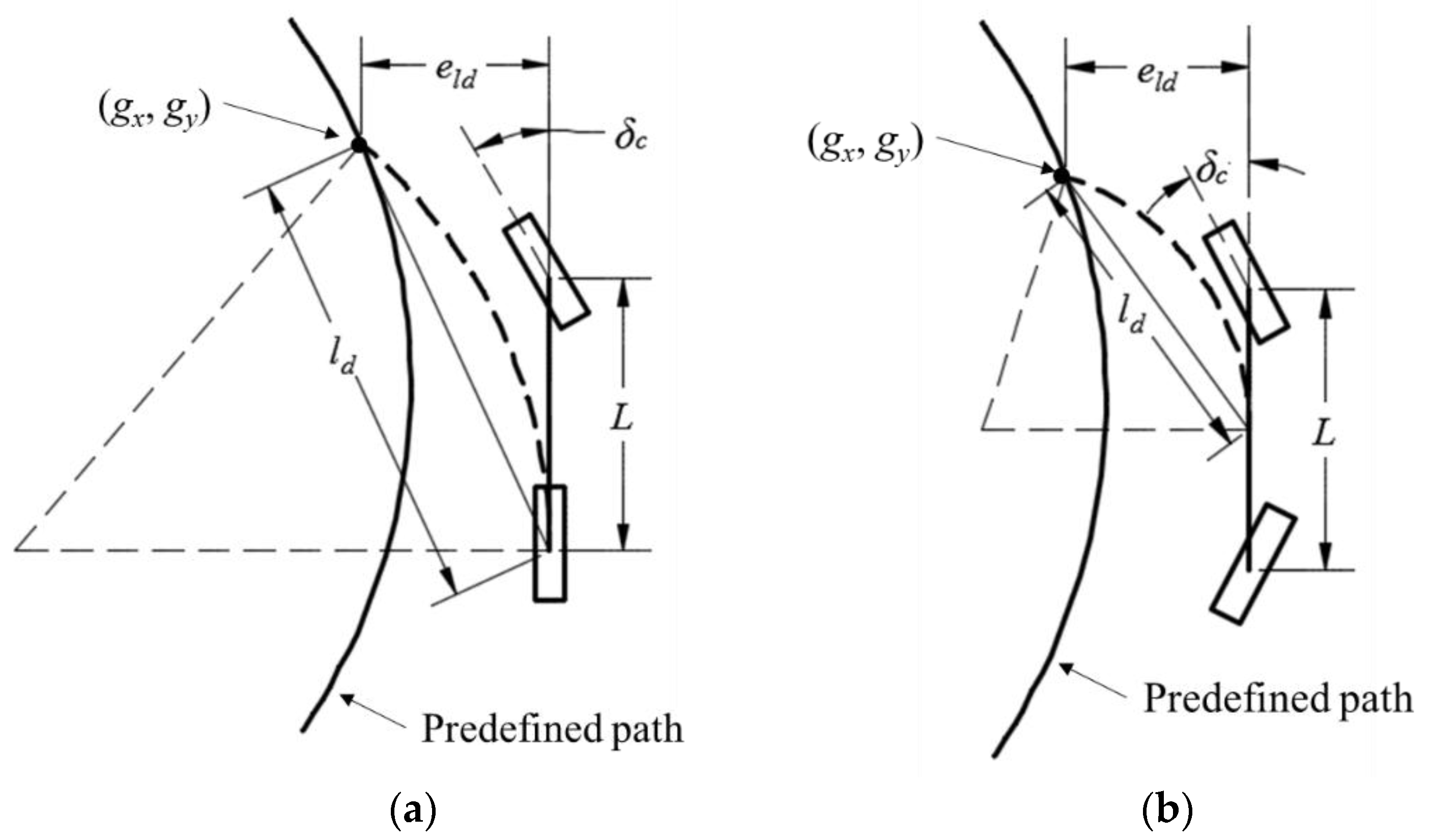
27] is used to guide the bin-dog to track a predefined path in the headland. The pure pursuit method (Figure 7) is used to calculate steering angles for both Ackermann and FRS steering.
In the figures, gx and gy are the coordinates of the navigation target point, ld is the look-ahead distance, δc is the steering angle, and eld is the offset of the target point. The pure pursuit method navigates the control point (located at the middle of two rear wheels for Ackermann steering and the geometry center for FRS) to the target point using a circular arc. The target point is found by searching for a point on a predicted path with a distance of ld to the control point. The steering angles for Ackermann and FRS steering determined by the pure pursuit method can be calculated using the following equations:
δ A C K E R = tan 1 ( 2 e l d L l d 2 )
δ FRS = tan 1 ( e l d L l d 2   )
As the global position of the bin-dog in the alleyway is not available, its localization in the alleyway is achieved by calculating its offset and heading angle relative to the alleyway centerline. In this study, the relative pose of the laser scanner for navigation (front laser scanner if driving forward and rear laser scanner if backward) is used as the pose of the bin-dog. This can be calculated using the equations below:
o f f s e t = D l D r 2
h e a d i n g   a n g l e = A l A r 2
where Dl, Dr denote the distance from the laser scanner to the left and right tree rows, and Al, Ar denote the angles between the bin-dog centerline and tree rows on both sides.
To find the accuracy of the pose computation, a perception experiment was conducted. In this experiment, the bin-dog stopped in an alleyway with different poses, and point clouds from the front laser scanner were used to calculate perceived poses. Table 1 shows the perceived poses and corresponding ground truths (manually measured separately by the researchers). The bin-dog was manually controlled to position it at each initial pose and the average value and root mean square errors (RMSEs) of heading angle and offset were calculated over a sequence of 100 readings from the front laser scanner. As can be seen, the differences between the perceived values and the ground truths were small (angle error less than 1.0° and distance error less than 0.05 m). Additionally, the RMSEs were almost identical to the average deviations, showing that the perception was stable and robust despite the noisy environment. Even though this was a static measurement, the results are non-trivial, as the branches and leaves were actually moving with wind. This shows that the localization in the alleyway is stable and capable of eliminating the effects of a noisy environment.

2.2.4. Object of Interest Detection

During bin management, the bin-dog needs to frequently interact with its surrounding environments to perform corresponding actions. For example, it needs to steer into a targeted tree alleyway from the headland and to be aligned with a bin when the bin is detected. To achieve this goal, we have built outline models for the objects. In our experiments at the orchard, there are two types of object to be identified: the tree rows and the bins. The implementation of this method is supported by the laser scanner installed on the bin-dog. Since the objects of interest are detected by sensing a linear hyperplane of their 3D shape, this results in a linear boundary identification. 
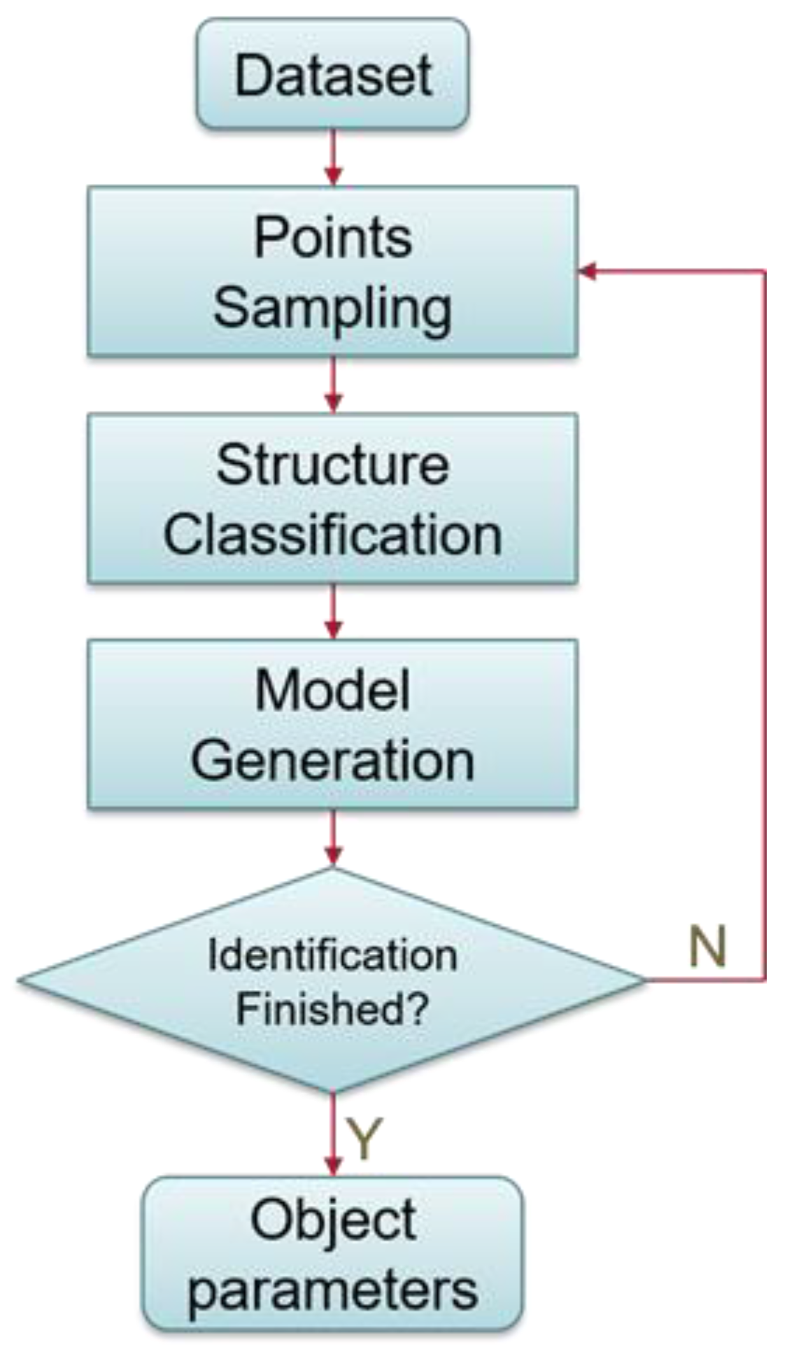
Figure 8 shows the flow diagram of the object detection algorithm. While identifying target objects, point clouds captured by the laser scanners (dataset) are sampled and streamed to the classification part (structure classification), where local structures are predicted. Local structures are then integrated to fit a model object. For example, if we are identifying a straight line, point clouds are used to first construct smaller line segments during structure classification. Then we integrate the line segments to generate a longer line model. Once the detection is complete, we are able to compute the relative poses of identified objects (such as distance and angle). Explanations on how this system work are provided as follows.
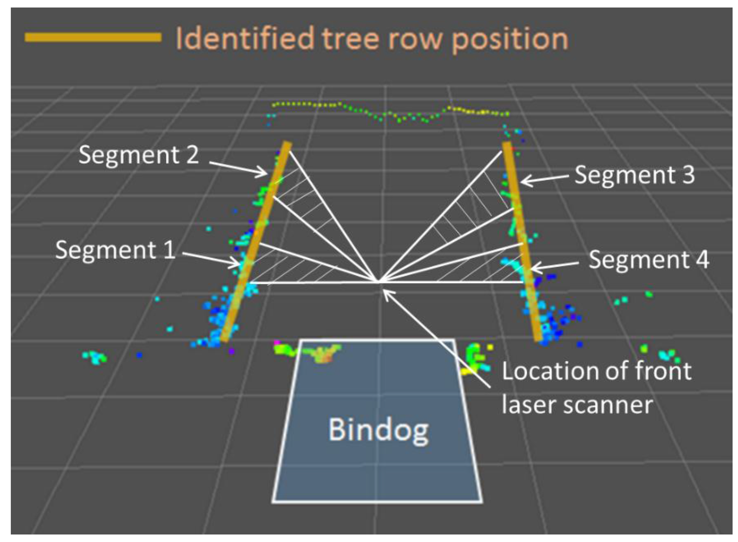
Tree row: Tree rows are important references for navigation when the bin-dog is working between them. As mentioned, in modern apple orchards, trees are planted in straight rows. Therefore, the point clouds of tree rows can be recognized as models of straight lines. To calculate the tree row model, we first select two sampling segments for a tree row (Figure 9). In each segment, we calculate the angle and distance of the line model formed by a pair of point clouds. The arithmetic means of angles and distances of the line models in a segment are used to represent the line model of the segment. Then, we calculate line model of the tree row by calculating the arithmetic mean of line models of two segments. Figure 9 illustrates the point clouds captured by a laser scan when bin-dog is driving between tree rows. Through the model identification algorithm shown above, we compute the relative angle (line slope) and distance (line bias) of the tree row, upon which we estimate the tree row position.
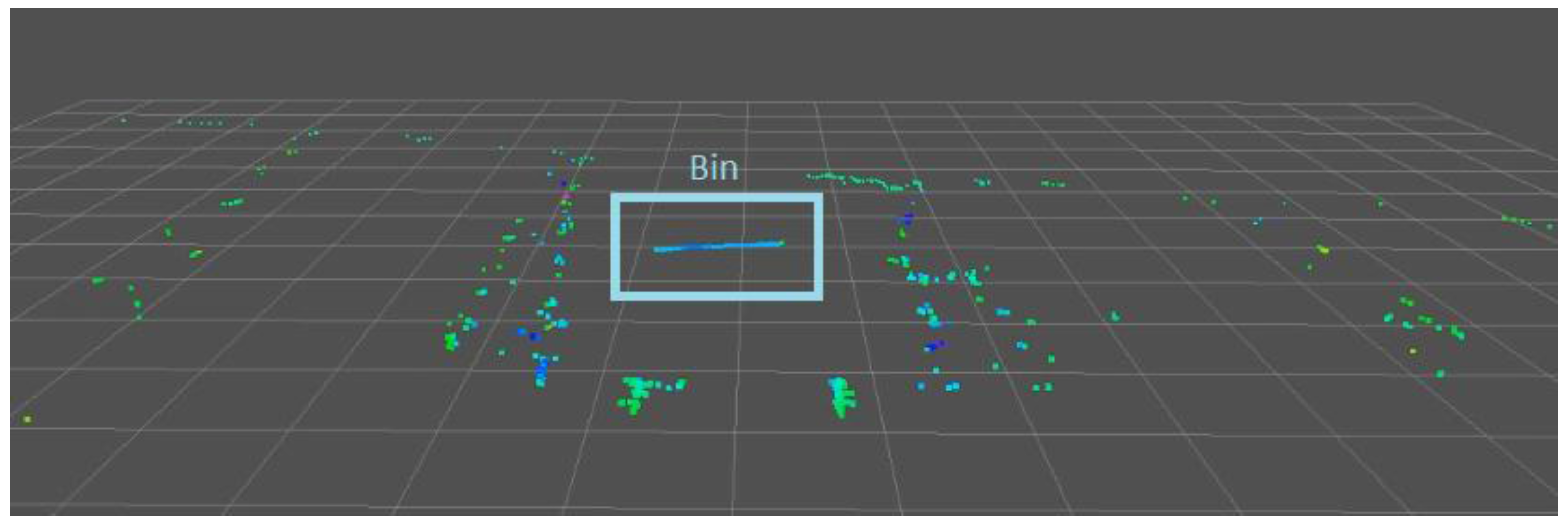
Bin: A typical fruit bin used during apple harvesting has a size of 1.20 m × 1.20 m × 1.00 m (width × length × height). The spacing between the two front wheels of the bin-dog is 1.40 m. Therefore, to successfully load a bin on the fork, it is important to precisely detect and locate the bin. Figure 10 shows the point clouds of a bin in an alleyway. As can be seen, the point clouds of the front side of a target bin (highlighted by a rectangle) form a horizontal straight line and contain little noise, which is in stark contrast to that of the tree rows. A straight line model is used to fit the perceived point clouds, which could represent the location of the bin. The RMSE of point clouds relative to the model has a magnitude order of 10−2 m, which is unique compared to the tree rows (10−1 m). Therefore, the algorithm can obtain highly accurate estimates of the relative position of the bin. Through the model identification algorithm shown above, we compute the relative angle (line slope) and distance (line bias), upon which we estimate bin positions.

2.2.5. Task Schedule

The entire bin-managing process needs to be completed in different environments through performing various actions in the correct order. Therefore, the task schedule module is used to determine the sequence of actions and specify the sensors and control strategy used in a task based on its environment. The tasks that need to be completed in the bin-managing process mainly include headland turning, straight-line tracking between tree rows, and “go-over-the-bin,” which are specified below. While Zhang [28] described the detailed algorithm development and validation results for task scheduling, a brief explanation on how this system works is provided as follows:
Headland turning: Headland turning is primarily performed to transition the bin-dog from the headland into the alleyways. Both the GPS and laser scanner-based navigation systems are used in this task. The GPS-based navigation is used to localize the bin-dog and track a predefined path that leads to the entrance of a targeted alleyway. Once the bin-dog reaches the marked location for the entrance and its heading angle has been adjusted towards the alleyway, the laser-based navigation is then used to guide it to enter the alleyway and stay on the alleyway centerline.
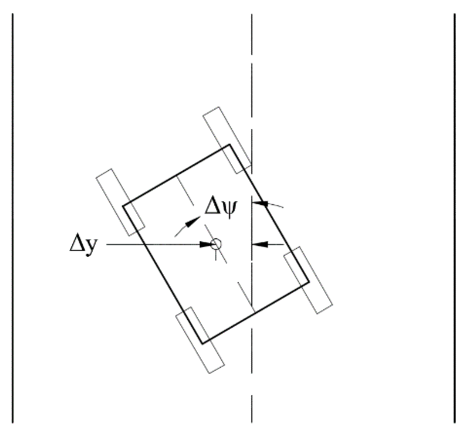
Straight-line tracking between tree rows: The task of straight-line tracking allows the bin-dog to navigate between tree rows without collision with tree rows. Therefore, in this task, the bin-dog needs to stay on the alleyway centerline and maintain a small pose error. The pose errors of the bin-dog in this task include lateral error (Δy) and the orientation error (Δψ) (Figure 11). They are used to calculate the steering angle for the low-level control system.
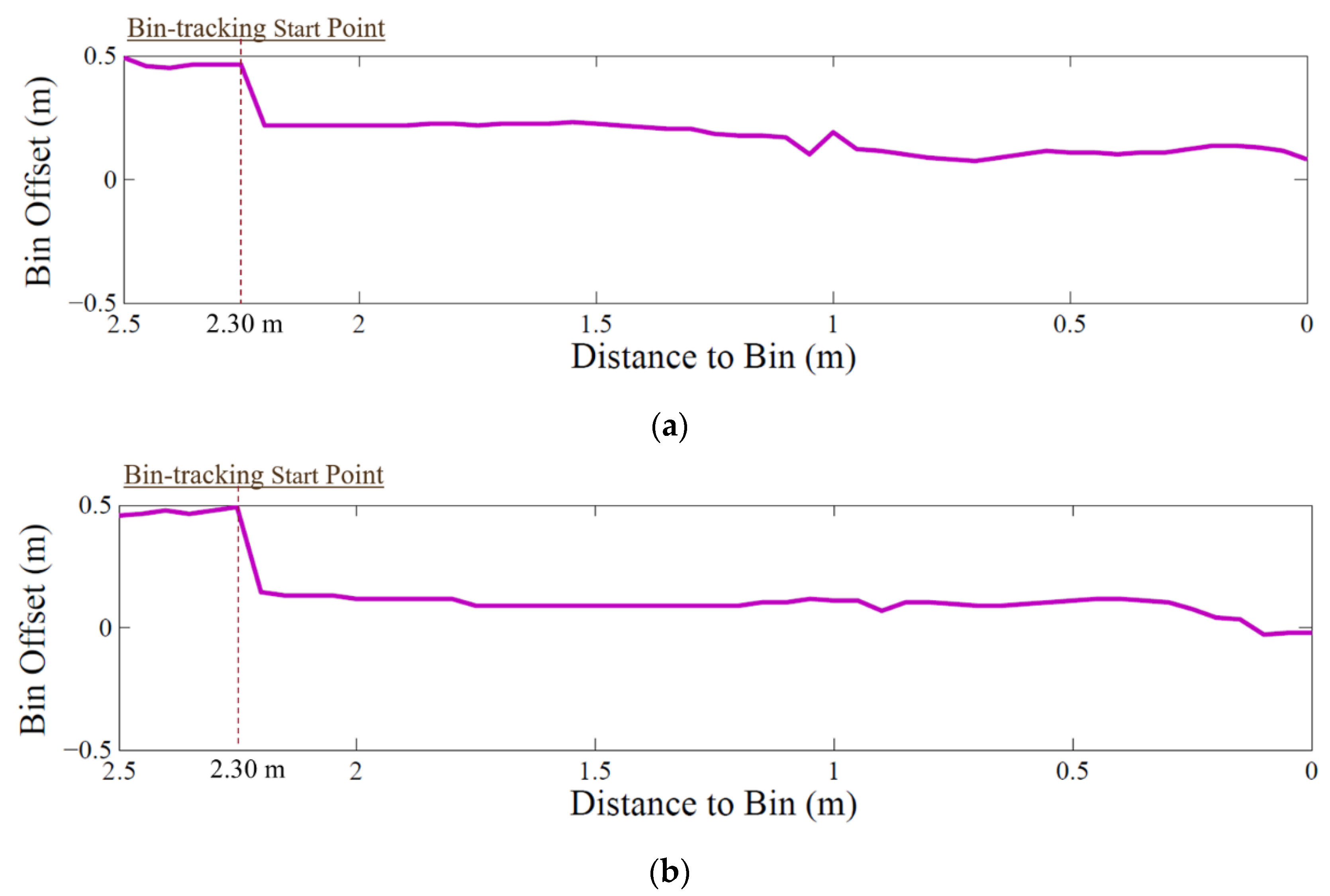
Go-over-the-bin: “Go-over-the-bin” is the core action for the bin-managing process. As mentioned in the previous section, it allows the bin-dog to replace a full bin with an empty bin in one trip. This task breaks down into a six-step process. In this task, (1) the bin-dog first carries an empty bin and uses the alleyway centerline as the reference to approach the full bin in the alleyway. Once its distance to the full bin is smaller than a preset threshold (2.30 m in our test), it lifts up the empty bin to a height of 1.2 m and uses the full bin as the reference for navigation. (2) When the full bin just gets under the front laser scanner, even though the laser scanner loses the point clouds of the front side of the bin, it can still capture point clouds from the body of the bin for reference. (3) As the bin-dog drives further forward, it completely loses the point clouds of the full bin. However, in such a situation, the bin-dog has already aligned with the bin and is partially above it. Therefore, it is set to keep driving straight forward for 20 s and then unload the empty bin. (4) Afterwards, the bin-dog lifts up its fork to 1.2 m and uses its rear laser scanner to drive over the full bin. (5) It then stops and lowers the fork to the ground, drives forward again until the full bin hits the touch switch on the fork, which triggers the fork lifting action. (6) Once the full bin is lifted off the ground (0.1 m), the bin-dog uses its rear laser scanner to drive backward and leave the alleyway.

2.3. Experimental Validation

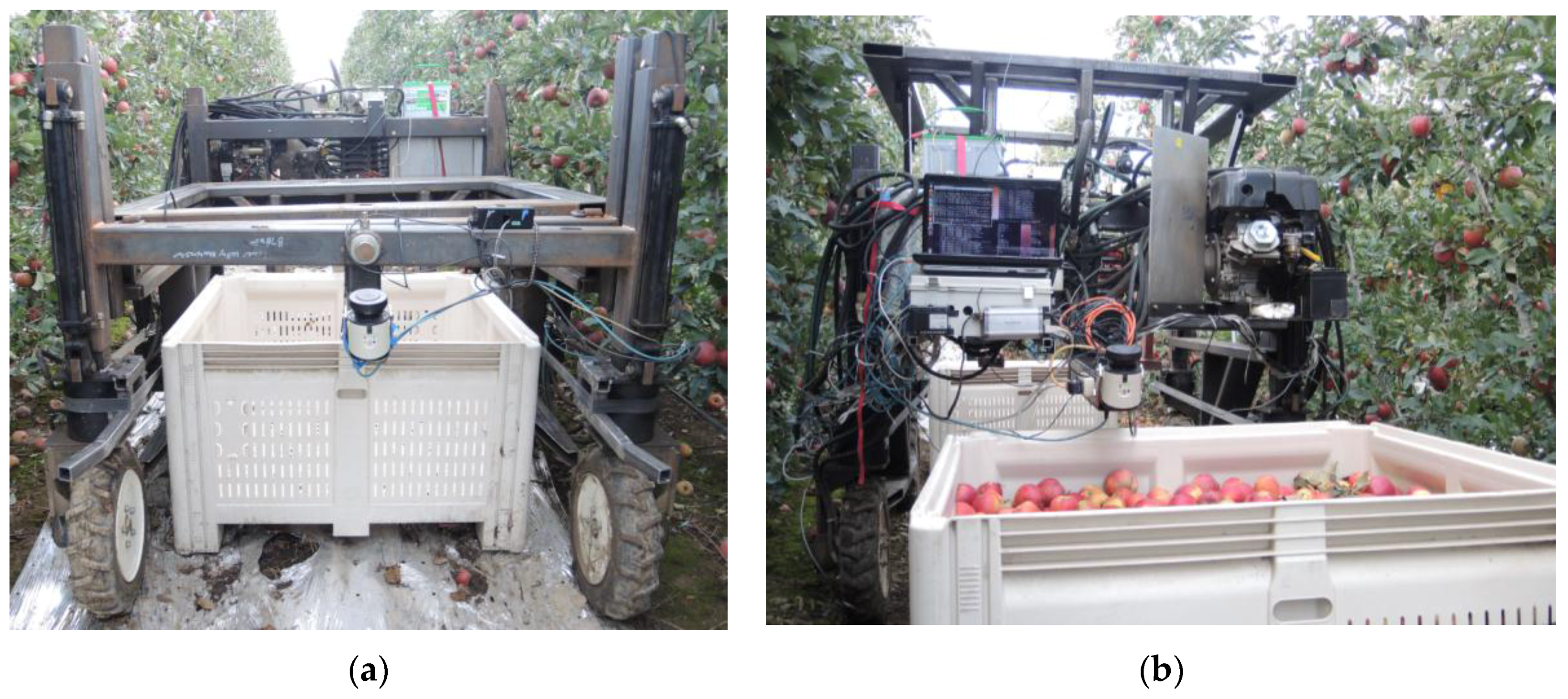
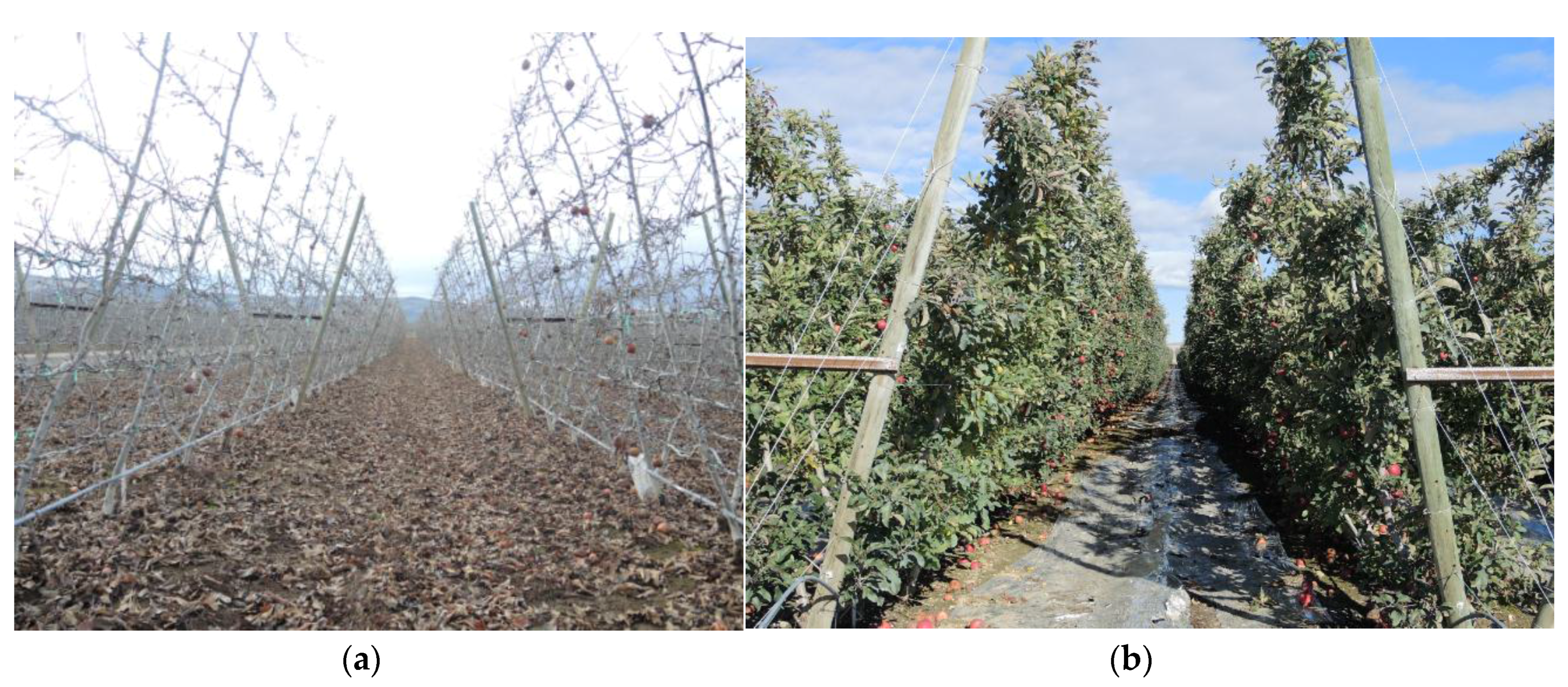
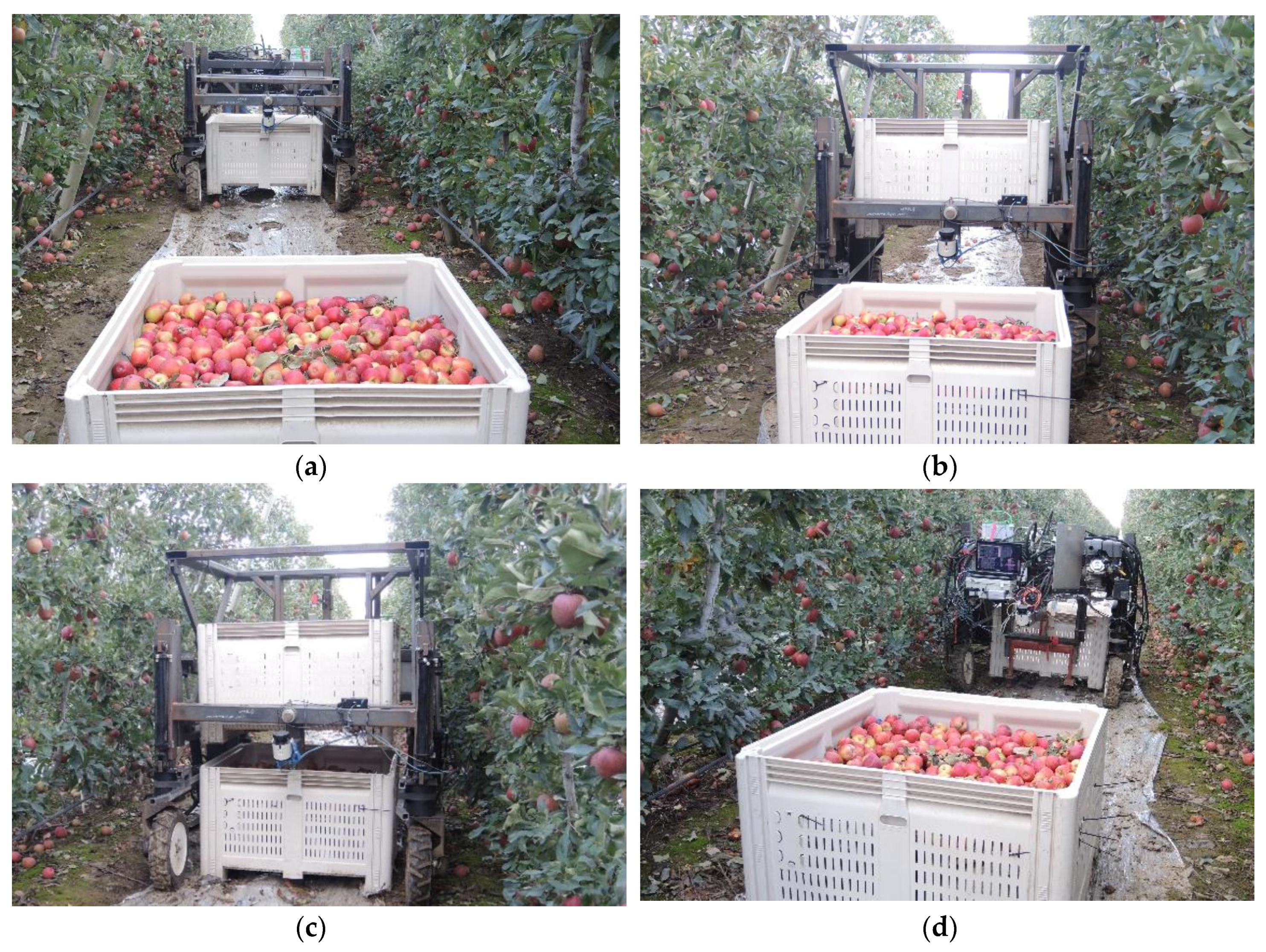
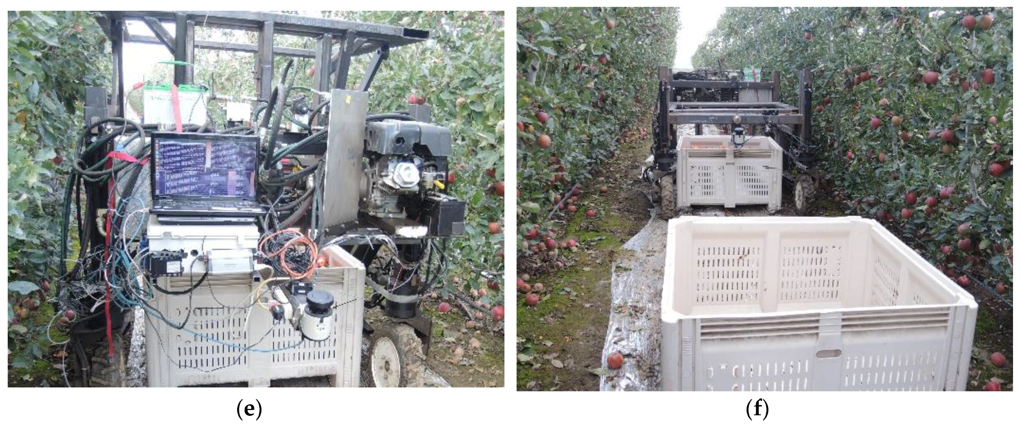
To test and validate the performance of the bin-dog system, extensive tests were performed in a commercial orchard in Yakima Valley of Eastern Washington. The prototype of the bin-dog was fabricated in 2015, and a series of field validation experiments were conducted in different seasons of 2015 and 2016 in a V-trellis fruiting wall commercial orchard in PNW (Figure 12a,b). The orchard had an inter-row spacing ranging from 2.30 m to 2.40 m at a height of 1.50 m and the width of its headland was 6.00 m. Notice that the experiments conducted in winter were more challenging than it would be in normal operation as the defoliation of the trees made the laser scanner much more difficult to detect the tree rows. In total, more than 200 testing runs were conducted in these field experiments, with some of them recording performance data and others used for performance observation. These test runs can be converted into over 40 km of bin management traversals in the orchard. This section highlights a set of experiments sufficient to demonstrate the performance of our prototype and the control methods used.

2.3.1. Headland Turning

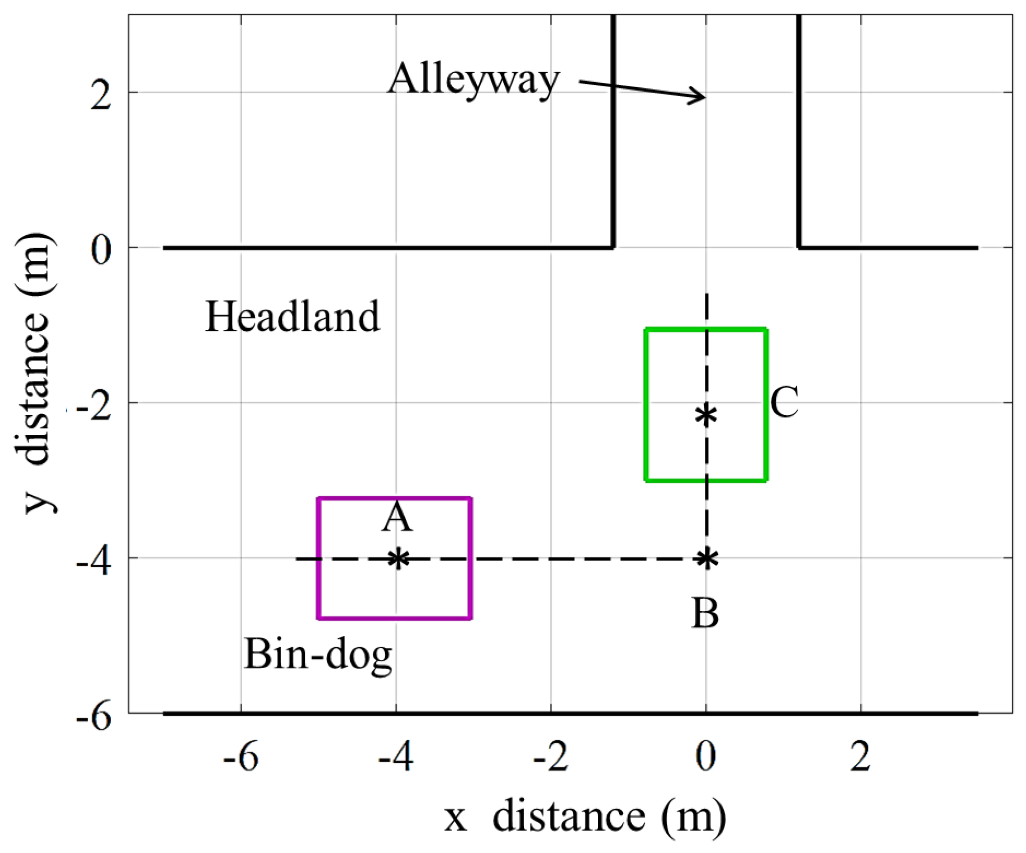
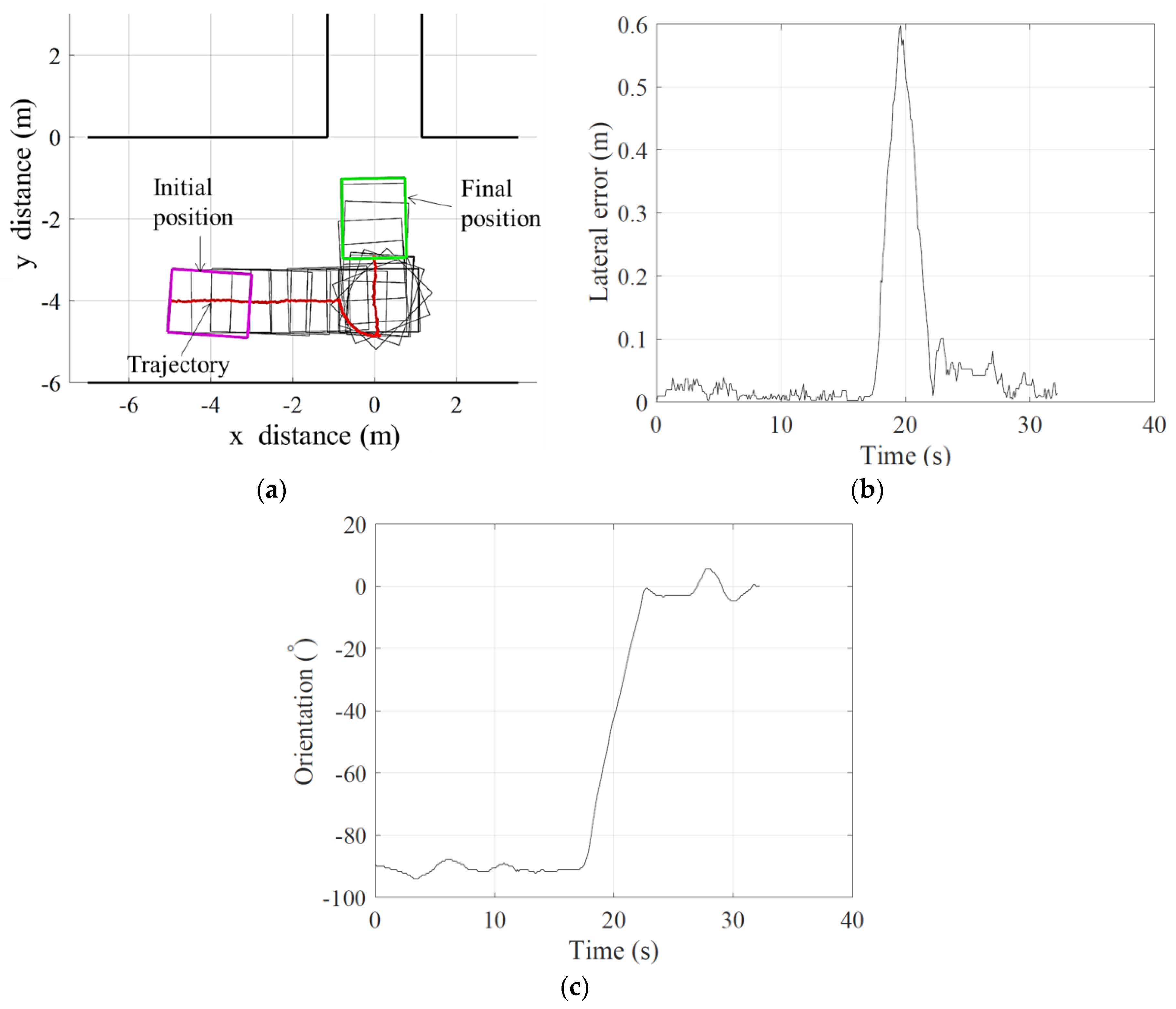
The test of headland turning was conducted to assess the headland turning performance of the bin-dog. As illustrated in Figure 13, in this test, the bin-dog was initially heading east and stopped at point A (−4, −4) m on the headland which was 4 m away from the entrance of an alleyway. When the test started, the bin-dog used Ackermann steering to track a straight line until it reached point B (0, −4) m. The steering mode then switched into spinning mode, and the bin-dog rotated counter-clockwise until its heading vector was parallel to the alleyway. The steering mode switched back to Ackermann steering again and the bin-dog followed a straight line to reach point C (0, −2) m. In this test, the location information from GPS and orientation information from IMU were used to compare with their theoretical values to calculate lateral errors and orientation of the bin-dog. The speed of the bin-dog in this test was fixed at 0.40 m·s−1, and the test had three repetitions.
The GPS location of the middle point of the rear wheels (tracking point) and heading angle of the bin-dog were recorded through the test. In this test, the lateral error of a data point is defined as the shortest distance from it to the path. The orientation error is defined as the angle between the heading vector of the bin-dog and the direction of the alleyway. Since rotation during the spinning mode was achieved by tracking the desired heading angle instead of tracking a path, the calculation of RMSE of lateral error does not include the spinning component of the trajectory. The observation on more than 40 repeat tests over a two-year testing period resulted in very similar performance.

2.3.2. Straight Line Tracking between Tree Rows

Driving speed is a factor that could influence the path tracking performance between tree rows. To achieve both efficient operation and smooth trajectory tracking, the desired speed of the system should be selected so as to properly balance between these two metrics. To examine this trade-off, in this test, three different test speed settings were selected: 0.30 m·s−1, 0.60 m·s−1, and 1.00 m·s−1. With each speed setting, the bin-dog navigated along the alleyway for 20 m and repeated for five times. In addition, numerous repeating tests from 20 m to 250 m (the whole length of the alleyway) tracking were observed without recording the performance data over the two-year testing period. All observed tests could successfully complete the task and resulted in very similar performance.

2.3.3. “Go-over-the-bin”

The test was set up to validate and evaluate the “go-over-the-bin” function of the bin-dog. In this test, we placed a full bin in an alleyway which had a 0°-heading angle and 0 m offset to the alleyway centerline. The bin-dog initially carried an empty bin to a location in the alleyway that was 5 m away from the full bin. It followed the “go-over-the-bin” work process described in task schedule section to unload the empty bin and remove the full bin. The test had five repetitions and the driving speed of the bin-dog was fixed at 0.60 m·s−1. Similar to other tasks, more than 20 repeated tests were observed without recording the performance data over the two-year testing period.

3. Results and Discussions

3.1. Headland Turning

Figure 14a illustrates the result of headland turning. In the figure, the solid line is the trajectory of the tracking point. The location of the frame of the bin-dog is calculated based on the trajectory and its heading angles measured by the IMU.
Figure 14b,c illustrate the errors in the lateral distance and the orientations of the bin-dog relative to the planned trajectory. For all three repetitions, the RMSE of lateral error was 0.04 m. This indicates that the bin-dog can use the GPS-based navigation system to precisely follow a predefined path on headland. When the bin-dog was close to the entrance, it adjusted its heading angle by rotating using the spinning mode. This led to a position drift of the tracking point, which resulted in a large lateral error spike as shown in Figure 14b. When the bin-dog completed the headland turning task, the final lateral and orientation errors for three repetitions were 0.02 m and 1.5° on average. The relatively small errors make it easy for the front laser scanner to detect the tree row entrance and can reduce the unstable path tracking caused by the transition to laser-based navigation.

3.2. Straight Line Tracking between Tree Rows

Table 2 shows the results of straight line tracking between tree rows with three speed settings (data were averaged over the 100 m long trajectory). For all three selected speeds, there were always steady state errors between the desired speeds and actual speeds, which is common for field robots, particularly in orchard environments. As the driving speed increased, the RMSE and maximum of lateral and orientation errors also increased. As shown in Table 2, the RMSE and maximum of the lateral error were 0.04 m and 0.17 m when desired bin-dog driving speed was 0.30 m·s−1, while those were 0.07 m, and 0.21 m, respectively under the desired driving speed of 1.00 m·s−1. However, when the bin-dog was on the centerline of an alleyway with 2.40 m width and parallel with it, the distances from left and right frames of the bin-dog to the tree rows were about 0.42 m. Therefore, the tracking performances under all three speed settings allowed the bin-dog to track the centerline without collision.

3.3. “Go-over-the-bin”

Figure 15 shows the “go-over-the-bin” process during the test. In Figure 15a, the bin-dog carried an empty bin when approaching the full bin. The bin-dog used the alleyway centerline as the reference to drive forward until the full bin was 2.30 m away. Then the bin-dog used the full bin, instead, as the reference to align with (Figure 15b). When the front laser scanner lost the full bin in its field of view, the bin-dog kept driving straight forward for a short distance to go over the full bin (Figure 15c). It then used tree rows as references again to drive forward and unloaded the empty bin (Figure 15d). Afterwards, it lifted up the fork, used the rear laser scanner to find the full bin and drove over it (Figure 15e). Then, it lowered the fork to the ground and drove forward to load the full bin until the bin triggered the touch switch on the fork. In the end, the bin-dog lifted the bin off the ground (Figure 15e) and left the alleyway. The entire process took 79.7 s on average over five repetitions. Based on our preliminary study, it took a fork-lift tractor about 60 s on average to remove a full bin and deliver an empty bin with a similar configuration to those in this test. However, in actual bin management, the bin-dog only needs to enter or leave the alleyway once, which would improve its overall efficiency comparing to conventional tractors. It is also possible to further improve the working efficiency of the bin-dog by increasing its operating speed and reducing stop times between steps.
To successfully go over a target bin, high accuracy motion control must be achieved. Figure 16 shows two example trajectories of the bin-dog approaching the full bin in the test (forward and backward). The x-axes of Figure 16a,b are the distances between the front/back side of the full bin and the front/back laser scanner along the direction of the alleyway. The y-axis is the bin offset, which is the distance between the laser scanner and the bin along the direction that is perpendicular to the alleyway. As the figures show, the bin-dog did not use the full bin as the reference until it was 2.30 m away from it. Once the bin-dog started to use the bin as the reference, the bin offset decreased, and the bin-dog maintained the offset until it reached the bin. Furthermore, when the bin-dog engaged with the bin (distance to the bin equals to 0 m), the average bin offset was 0.08 m. The space between the front/rear wheels of the bin-dog was 1.40 m, while the width of an apple bin was 1.20 m. The maximum bin offset should be less than 0.10 m to ensure the engagement of the bin-dog with the bin. The results from this test indicates that in the task of “go-over-the-bin,” the bin-dog can drive over a bin without colliding with the tree rows or the bin.

4. Conclusions

An innovative bin-dog system for robotic bin management has been developed and tested in this study. The developed prototype is designed with a “go-over-the-bin” function, which allows the system to replace a full bin with an empty bin in one trip. It can be guided by a GPS and laser scanner-based navigation system to complete bin-managing tasks in both headlands and between tree rows. Bin-managing tasks that are critical for bin management, including heading turning, straight line tracking between tree rows, and “go-over-the-bin,” have been successfully completed and validated in a commercial orchard. Validation tests showed that it can follow a predefined path to align with an alleyway with lateral and orientation errors of 0.02 m and 1.5°. Tests of straight-line tracking showed that the bin-dog system can successfully track the center line of two tree rows at speeds up to 1.00 m·s−1 with a RMSE of offset of 0.07 m. The navigation system also successfully guided the bin-dog to complete the “go-over-the-bin” task at a speed of 0.60 m·s−1 without collision with tree rows or the bins. The prototype’s successful autonomous operation of over 40 km, as well as the successful validation tests, showed that the prototype can achieve all designated functionalities. Thus, it is feasible to use the bin-dog system to achieve bin management using the novel with “go-over-the-bin” function without direct operator control.

Acknowledgments

This research was partially supported in part by USDA Hatch and Multistate Project Funds (Accession Nos. 1005756 and 1001246), a USDA National Institute for Food and Agriculture (NIFA) competitive grant (Accession No. 1003828), and the Washington State University (WSU) Agricultural Research Center (ARC). The China Scholarship Council (CSC) partially sponsored Yunxiang Ye in conducting dissertation research at the WSU Center for Precision and Automated Agricultural Systems (CPAAS). Any opinions, findings, conclusions, or recommendations expressed in this publication are those of the authors and do not necessarily reflect the view of USDA and WSU. This research has taken place in part at the Intelligent Robot Learning (IRL) Lab, Washington State University. IRL’s support includes NASA NNX16CD07C, NSF IIS-1149917, NSF IIS-1643614, and USDA 2014-67021-22174.

Author Contributions

Yunxiang Ye and Long He contributed to the design and implementation of the hardware of the bin-dog system, supervised by Qin Zhang; Zhaodong Wang, Yunxiang Ye, and Dylan Jones contributed to design the low-level control system and navigation system, supervised by Matthew E. Taylor and Geoffrey A. Hollinger.

Conflicts of Interest

The authors declare no conflict of interest.

References

  1. USDA, National Agricultural Statistics Service. Agricultural statistics annual. Available online: https://quickstats.nass.usda.gov/results/BA508004-43F6-3D06-B1E5-4449119391AB (accessed on 1 May 2017).
  2. Hertz, T.; Zahniser, S. Is there a farm labor shortage? Am. J. Agric. Econ. 2013, 95, 476–481. [Google Scholar] [CrossRef]
  3. Peterson, L.; Monroe, E. Continuously Moving Shake-Catch Harvester for Tree Crops. Trans. ASAE 1977, 20, 202–205. [Google Scholar] [CrossRef]
  4. Peterson, L.; Bennedsen, S.; Anger, C.; Wolford, D. A systems approach to robotic bulk harvesting of apples. Trans. ASAE 1999, 42, 871–876. [Google Scholar] [CrossRef]
  5. Peterson, L. Development of a harvest aid for narrow-inclined-trellised tree-fruit canopies. Appl. Eng. Agric. 2005, 21, 803–806. [Google Scholar] [CrossRef]
  6. Schupp, J.; Baugher, T.; Winzeler, E.; Schupp, M.; Messner, W. Preliminary results with a vacuum assisted harvest system for apples. Fruit Notes 2011, 76, 1–5. [Google Scholar]
  7. O’Connor, M.; Bell, T.; Elkaim, G.; Parkinson, B. Automatic steering of farm vehicle using GPS. In Proceedings of the 3rd International Conference on Precision Agriculture, Minneapolis, MI, USA, 23–26 June 1996. [Google Scholar]
  8. Stombaugh, S.; Benson, R.; Hummel, W. Automatic guidance of agricultural vehicles at high field speeds. In Proceedings of the 1998 ASAE Annual International Meeting, Orlando, FL, USA, 12–16 July 1998. [Google Scholar]
  9. Zhang, Q.; Qiu, H. A Dynamic Path Search Algorithm for Tractor Automatic Navigation. Trans. ASAE 2004, 47, 639–646. [Google Scholar] [CrossRef]
  10. Roberson, T.; Jordan, L. RTK GPS and automatic steering for peanut digging. Appl. Eng. Agric. 2014, 30, 405–409. [Google Scholar]
  11. Heraud, J.A.; Lange, A.F. Agricultural Automatic Vehicle Guidance from Horses to GPS: How We Got Here, and Where We Are Going. In Proceedings of the 2009 Agricultural Equipment Technology Conference, Louisville, KY, USA, 9–12 February 2009. [Google Scholar]
  12. Baio, F. Evaluation of an auto-guidance system operating on a sugar cane harvester. Precis. Agric. 2012, 13, 141–147. [Google Scholar] [CrossRef]
  13. Subramanian, V.; Burks, F.; Arroyo, A. Development of machine vision and laser radar based autonomous vehicle guidance systems for citrus grove navigation. Comput. Electron. Agric. 2006, 53, 130–143. [Google Scholar] [CrossRef]
  14. Tumbo, D.; Salyani, M.; Whitney, D.; Wheaton, A.; Miller, M. Investigation of laser and ultrasonic ranging sensors for measurements of citrus canopy volume. Appl. Eng. Agric. 2002, 18, 367–372. [Google Scholar] [CrossRef]
  15. Wei, J.; Salyani, M. Development of a laser scanner for measuring tree canopy characteristics. ASAE Ann. Int. Meet. 2004, 47, 2101–2107. [Google Scholar]
  16. Rosell, J.R.; Llorens, J.; Sanz, R.; Arnó, J.; Ribes-Dasi, M.; Masip, J.; Palacín, J. Obtaining the three-dimensional structure of tree orchards from remote 2D terrestrial LIDAR scanning. Agric. For. Meteorol. 2009, 149, 1505–1515. [Google Scholar] [CrossRef]
  17. Rosell, J.R.; Sanz, R. A review of methods and applications of the geometric characterization of tree crops in agricultural activities. Comput. Electron. Agric. 2012, 81, 124–141. [Google Scholar] [CrossRef]
  18. Sanz, R.; Rosell, R.; Llorens, J.; Gil, E.; Planas, S. Relationship between tree row LIDAR-volume and leaf area density for fruit orchards and vineyards obtained with a LIDAR 3D Dynamic Measurement System. Agric. For. Meteorol. 2013, 171, 153–162. [Google Scholar] [CrossRef]
  19. Shalal, N.; Low, T.; McCarthy, C.; Hancock, N. Orchard mapping and mobile robot localisation using on-board camera and laser scanner data fusion—Part A: Tree detection. Comput. Electron. Agric. 2015, 119, 254–266. [Google Scholar] [CrossRef]
  20. Barawid, O.; Mizushima, A.; Ishii, K.; Noguchi, N. Development of an Autonomous Navigation System using a Two-dimensional Laser Scanner in an Orchard Application. Biosyst. Eng. 2007, 96, 139–149. [Google Scholar] [CrossRef]
  21. Subramania, V.; Burks, T. Autonomous vehicle turning in the headlands of citrus groves. In Proceedings of the 2007 ASAE Annual Meeting, Minneapolis, MN, USA, 17–20 June 2007. [Google Scholar]
  22. Hamner, B.; Singh, S.; Bergerman, M. Improving Orchard Efficiency with Autonomous Utility Vehicles. In Proceedings of the 2010 ASABE Annual International Meeting, Pittsburgh, PA, USA, 20–23 June 2010. [Google Scholar]
  23. Hamner, B.; Bergerman, M.; Singh, S. Autonomous Orchard Vehicles for Specialty Crops Production. In Proceedings of the 2011 ASABE Annual International Meeting, Louisville, KY, USA, 7–10 August 2011. [Google Scholar]
  24. Bergerman, M.; Maeta, M.; Zhang, J.; Freitas, M.; Hamner, B.; Singh, S.; Kantor, G. Robot farmers: Autonomous orchard vehicles help tree fruit production. IEEE Robot. Autom. Mag. 2015, 22, 54–63. [Google Scholar] [CrossRef]
  25. Moorehead, J.; Wellington, C.; Gilmore, J.; Vallespi, C. Automating Orchards: A System of Autonomous Tractors for Orchard Maintenance. In Proceedings of the IEEE International Conference on Intelligent Robots and Systems, Workshop on Agricultural Robotics, Vilamoura, Algarve, 7–12 October 2012. [Google Scholar]
  26. Zhang, Y.; Ye, Y.; Zhang, W.; Taylor, M.; Hollinger, G.; Zhang, Q. Intelligent In-Orchard Bin-Managing System for Tree Fruit Production. In Proceedings of the Robotics in Agriculture Workshop at the 2015 IEEE International Conference on Robotics and Automation, Seattle, WA, USA, 30 May 2015. [Google Scholar]
  27. Ye, Y.; He, L.; Zhang, Q. A robotic platform “bin-dog” for bin management in orchard environment. In Proceedings of the 2016 ASABE Annual International Meeting, Orlando, FL, USA, 17–20 July 2016. [Google Scholar]
  28. Zhang, Y. Multi-Robot Coordination: Applications in Orchard Bin Management and Informative Path Planning. Master’s Thesis, Oregon State University, Corvallis, OR, USA, September 2015. [Google Scholar]
  29. Quigley, M.; Gerkey, B.; Conley, K.; Faust, J.; Foote, T.; Leibs, J.; Berger, E.; Wheeler, R.; Ng, A. ROS: An Open-source Robot Operating System. In Proceedings of the IEEE International Conference on Robotics and Automation, Workshop on Open Source Software, Kobe, Japan, 17 May 2009. [Google Scholar]
Figure 1. The five-step bin management process with the bin-dog.
Robotics 06 00012 g001
Figure 2. Research prototype of the bin-dog.
Robotics 06 00012 g002
Figure 3. Steering modes of the bin-dog. (a) Ackermann steering; (b) front-and-rear-steering; (c) spinning; (d) crab steering. In the figure, δ1, δ2, δ3, δ4 are steering angles of each wheels and I is the instantaneous center of rotation.
Robotics 06 00012 g003
Figure 4. Physical architecture of the bin-dog low level driving and steering control system.
Robotics 06 00012 g004
Figure 5. Structure of navigation system in the Robot Operating System.
Robotics 06 00012 g005
Figure 6. Installation of front and rear laser scanners. (a) Front laser scanner; (b) rear laser scanner.
Robotics 06 00012 g006
Figure 7. Schematics of the pure pursuit method. (a) Ackermann steering, and (b) front-and-rear-steering.
Robotics 06 00012 g007
Figure 8. Diagram of object detection.
Robotics 06 00012 g008
Figure 9. Tree row identification and localization, where laser signal points with higher intensity are displayed with a higher RGB value.
Robotics 06 00012 g009
Figure 10. Bin object identification and localization, where laser signal points with higher intensity are displayed with a higher RGB value.
Robotics 06 00012 g010
Figure 11. The dashed line is the alleyway centerline. Based on relative pose of the bin-dog, we calculate the lateral error Δy and the orientation error Δψ.
Robotics 06 00012 g011
Figure 12. The apple orchard environment during the navigational test. (a) Orchard in winter and (b) orchard in summer.
Robotics 06 00012 g012
Figure 13. Test setup of headland turning.
Robotics 06 00012 g013
Figure 14. Test results of headland turning. (a) Actual trajectory in the test; (b) lateral in the tests; (c) orientation in the tests.
Robotics 06 00012 g014
Figure 15. A six-step “go-over-the-bin” process. (a) The bin-dog carries an empty bin to approach a full bin; (b) lifts empty bin; (c) drives over the full bin; (d) unloads the empty bin behind the full bin; (e) drives backward to go over the full bin again; (f) loads the full bin.
Robotics 06 00012 g015aRobotics 06 00012 g015b
Figure 16. Bin tracking trajectory when driving over a bin. (a) Forward; (b) backward.
Robotics 06 00012 g016
Table 1. Ground truth and perceived position value from the navigation algorithm using a laser scanner.
Ground TruthHeading Angle (°)Offset (m)
+20.00.0−20.0+0.20.0−0.2
Average perceived value20.30.3−19.70.220.02−1.98
Average deviation0.30.30.30.020.020.03
RMSE0.30.30.30.020.020.02
Table 2. Path tracking performance with different desired driving speed.
Desired Speed (m·s−1)Average Speed (m·s−1)RMSE of Lateral Error (m)Max Lateral Error (m)RMSE of Orientation Error (°)Max Orientation Error (°)
0.300.260.040.176.613.5
0.600.540.070.177.114.3
1.000.850.070.219.416.8

