
HBS-1: A Modular Child-Size 3D Printed Humanoid


Abstract
:1. Introduction
1.1. Humanoids with Legged Motion
1.2. Humanlike Robots
1.3. Controllers Used in Humanoid Robots
1.4. Sensors Used in Humanoid Robots
1.5. Comparison of Actuators Used in Humanoid Robots
1.6. Goals of the Paper
2. Design Approach of Humanoids
2.1. Bioinspired Musculoskeletal Design Approach
2.2. Minimization of Actuators Approach
2.3. Concurrent Engineering Approach
2.4. Specific Functionality Approach
2.5. Modular Behavior-Based Approach
2.6. Design for Assembly and Design for Manufacturing Approaches

| Guidelines DFA | Example |
|---|---|
| Minimize the number of parts | HBS: the entire design. |
| Minimize the number of assembly operations | HBS: arms assembly (complex in shape). |
| Self-locating structures on part design | HBS: the entire torso design, pelvis and legs. |
| Modular design | HBS: each part can be made separately and assembled. |
| Part design symmetry | HBS: most parts. |
| Standardize parts and minimum use of fasteners | HBS: considering the manufacturing methods (8 × 8 × 11 in 3D |
| printer), the number of fasteners was ~60. | |
| Ease of part handling and insertion | HBS: all parts can be assembled without requiring special tools. |
| Guidelines DFM | Example |
| Ease of manufacturing(form, material and size) | HBS: almost 90% of the parts are 3D printed. |
| Use of standards parts | HBS: off the shelf fasteners, brackets and actuators. |
| Easily-made custom parts | HBS: the finger joints: metacarpophalangeal joints (MCP), |
| proximal interphalangeal joints( PIP) and distal interphalangeal | |
| joint (DIP) used torsional springs made of music wire. | |
| Capability of the manufacturing process | HBS: the gap between 3D printed moving parts was limited to |
| 0.45 mm to minimize friction; the minimum feature size in a part is | |
| >3 mm; the minimum resolution of layer printing is 0.178 mm. | |
| Part design symmetry | HBS: most parts. |
| Separate parts | HBS: considering the manufacturing methods (8 × 8 × 11 in 3D |
| printer), two parts were made; for example, the torso. | |
| Compliance | HBS: holes were chamfered, tapered and tolerance and a moderate radius were applied for the ease of insertion. |
3. Design and Fabrication
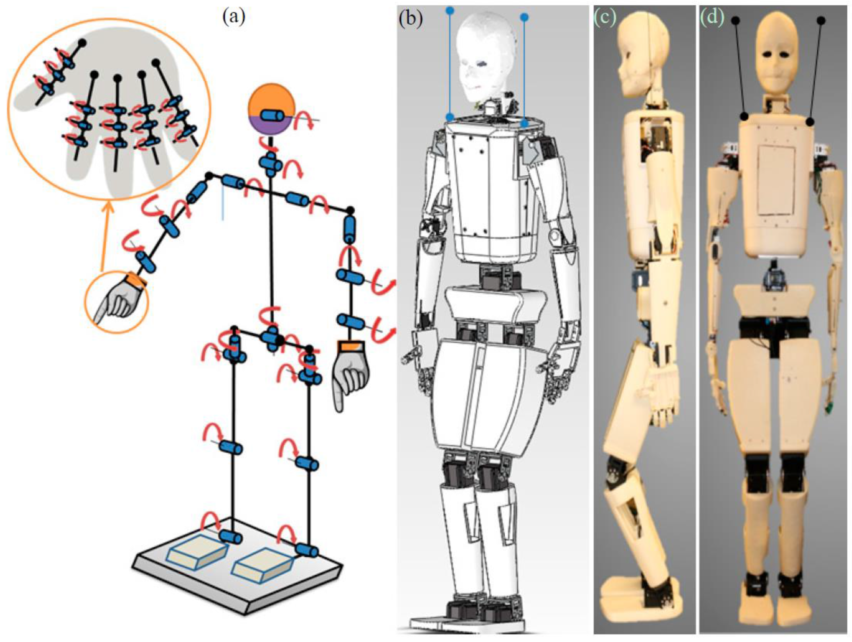
3.1. Mechanical System
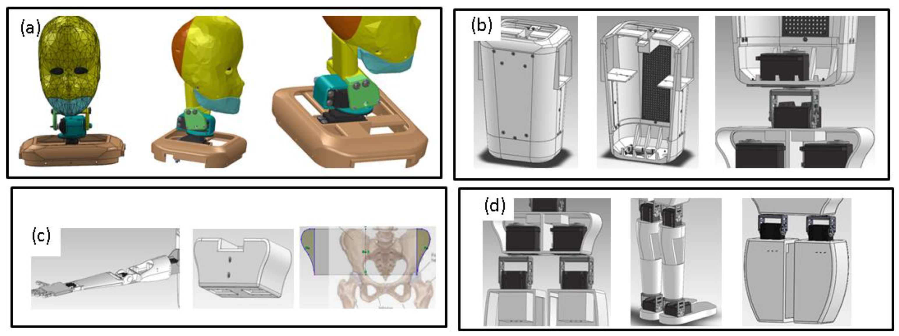
3.1.1. Head and Neck Design
3.1.2. Arm and Hand Design
3.1.3. Torso Design
3.1.4. Pelvis Design
3.1.5. Leg Design
3.2. Fabrication

3.3. Mechatronic Systems
3.3.1. Actuators and Sensors for HBS-1
3.3.2. Controllers for HBS-1
3.3.3. Software and Programming of HBS-1
3.4. Servo Motor Selection of HBS-1
3.4.1. Arms
| Link (Object) | Li (m) | Wi (N) | Mi (N) |
|---|---|---|---|
| Hand (block, i = 1) | 0.105 | 0.196 | 0.98 |
| Forearm (i = 2) | 0.136 | 0.686 | - |
| Bicep (i = 3) | 0.146 | 1.47 | - |
| Torso (i = 4) | 0.119 | 16.366 | 9.8 |
| Head (i = 5) | 0.210 | - | 19.6 |
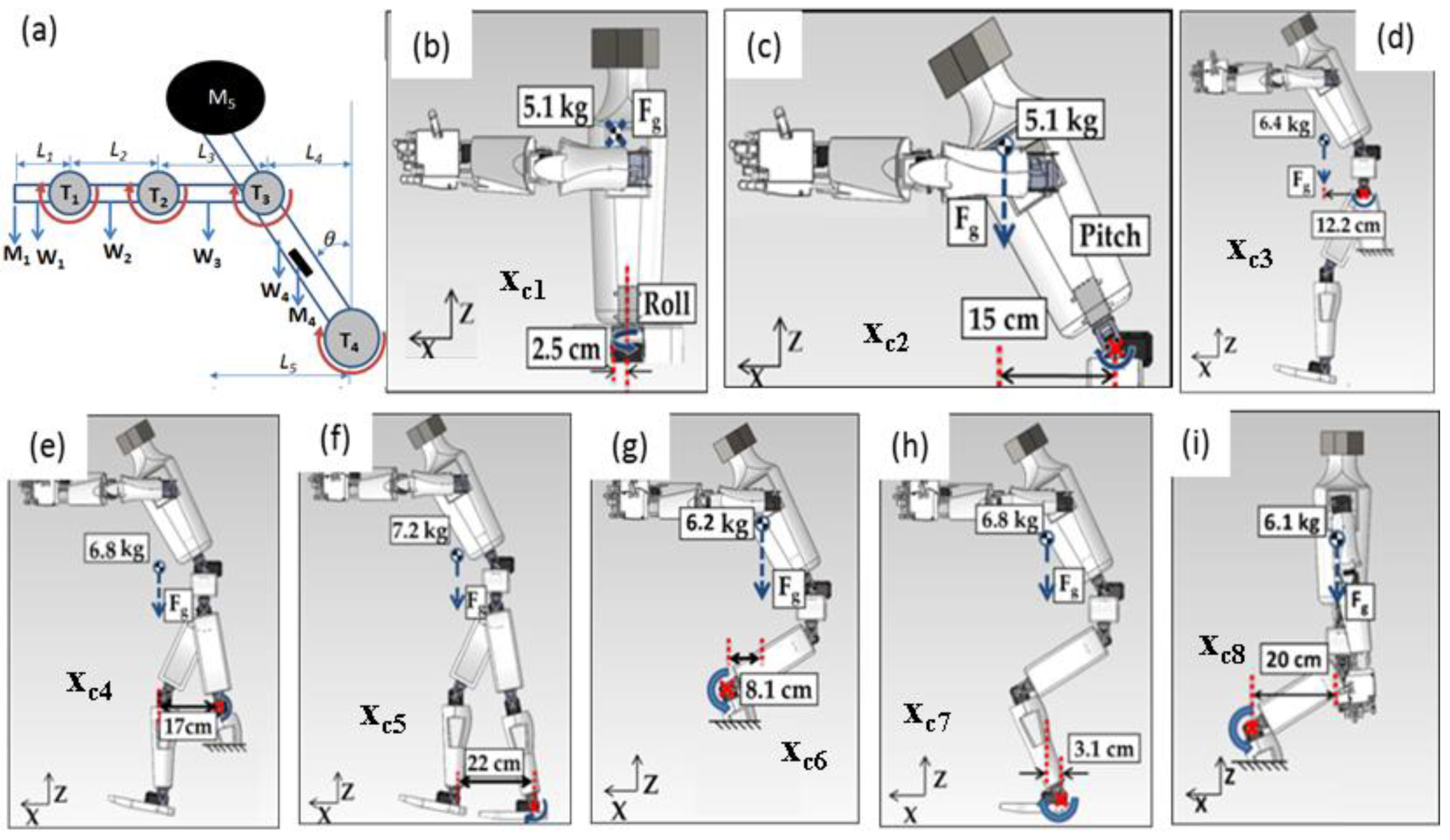
3.4.2. Torso
| Joint | Iyy | α | Ts | Td | Ti |
|---|---|---|---|---|---|
| (kg·m2) | (rad/s2) | (N·m) | (N·m) | (N·m) | |
| Wrist (i = 1) | 2 × 10⁻³ | 15 | 0.14 | 0.03 | 0.17 |
| Elbow (i = 2) | 0.01 | 15 | 0.32 | 0.17 | 0.49 |
| Shoulder (i = 3) | 0.03 | 15 | 0.90 | 0.45 | 1.37 |
| Torso-pitch (i = 4) | 0.47 | 3.5 | 7.25 | 1.67 | 8.82 |
| Torso-roll (i = 5) | 0.04 | 3.5 | 1.27 | 0.16 | 1.47 |
3.4.3. Legs
| Joint | xci | Mi | Iyy | α | Ts | Td | Ti |
|---|---|---|---|---|---|---|---|
| (m) | (N) | (kg·m2) | (rad/s2) | (N·m) | |||
| T-Pitch (i = 2) | 0.15 | 49.98 | 0.47 | 3.5 | 7.50 | 1.65 | 9.15 |
| T-Roll (i = 1) | 0.025 | 49.98 | 0.04 | 3.5 | 1.25 | 0.14 | 1.39 |
| First Pose: Leaning forward, one leg on ground | |||||||
| Thigh (i = 3) | 0.12 | 62.72 | 0.9 | 1.6 | 7.52 | 1.44 | 8.96 |
| Knee (i = 4) | 0.17 | 66.64 | 2.1 | 1.6 | 11.33 | 3.36 | 14.69 |
| Ankle (i = 5) | 0.22 | 70.56 | 4.3 | 1.6 | 15.52 | 6.88 | 22.40 |
| Second Pose: Squatting ** | |||||||
| Knee (i = 6) | 0.081 | 60.76 | 1.2 | 1.6 | 4.92 | 1.92 | 6.84 |
| Ankle (i = 7) | 0.031 | 66.64 | 2.8 | 1.6 | 2.06 | 4.48 | 6.55 |
| Third Pose: Sitting ** | |||||||
| Knee (i = 8) | 0.20 | 59.78 | 1.5 | 1.6 | 11.96 | 2.4 | 14.36 |
3.5. Shape Memory Alloy Selection for the Fingers
4. Modeling and Analysis
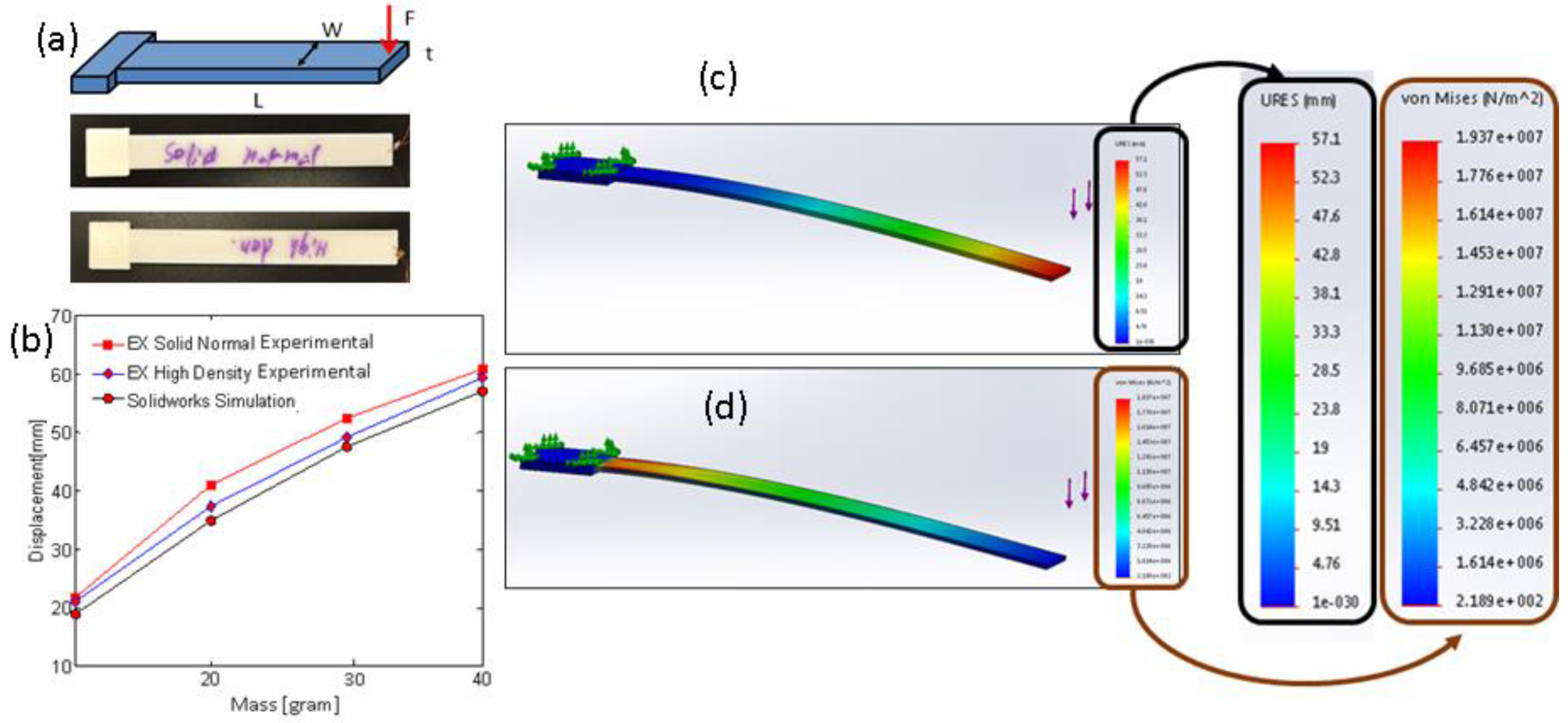
4.1. Stress and Deformation Simulation
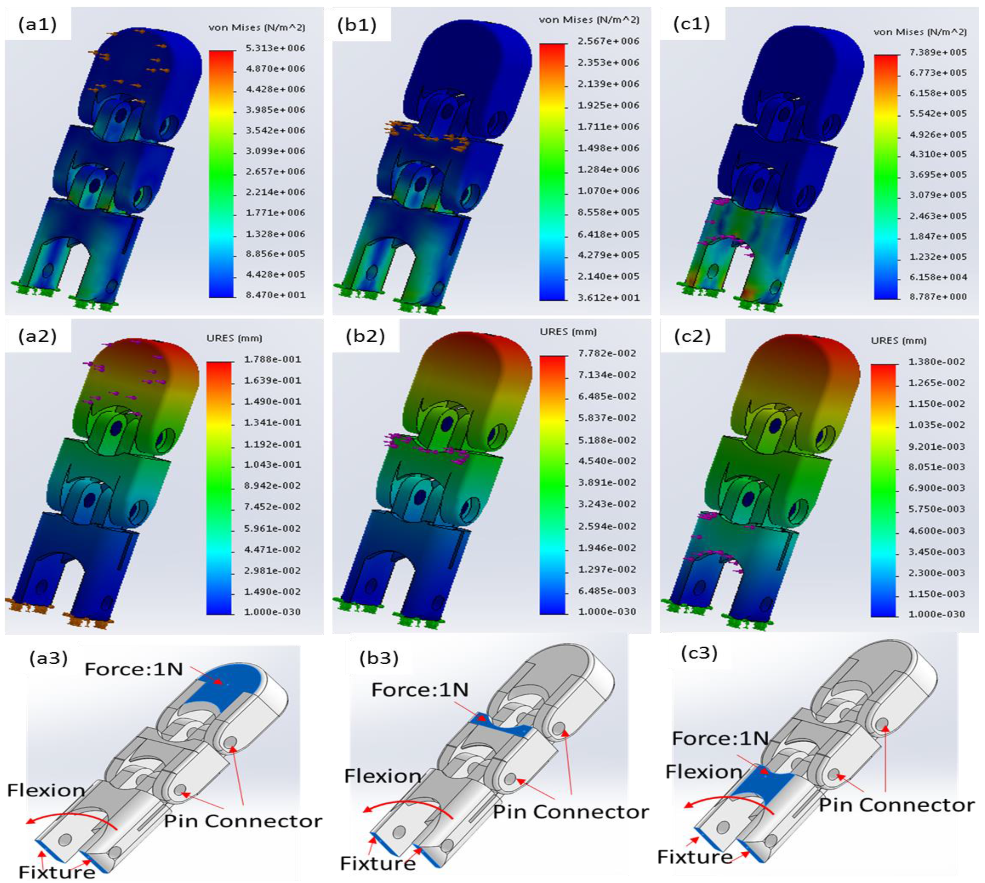
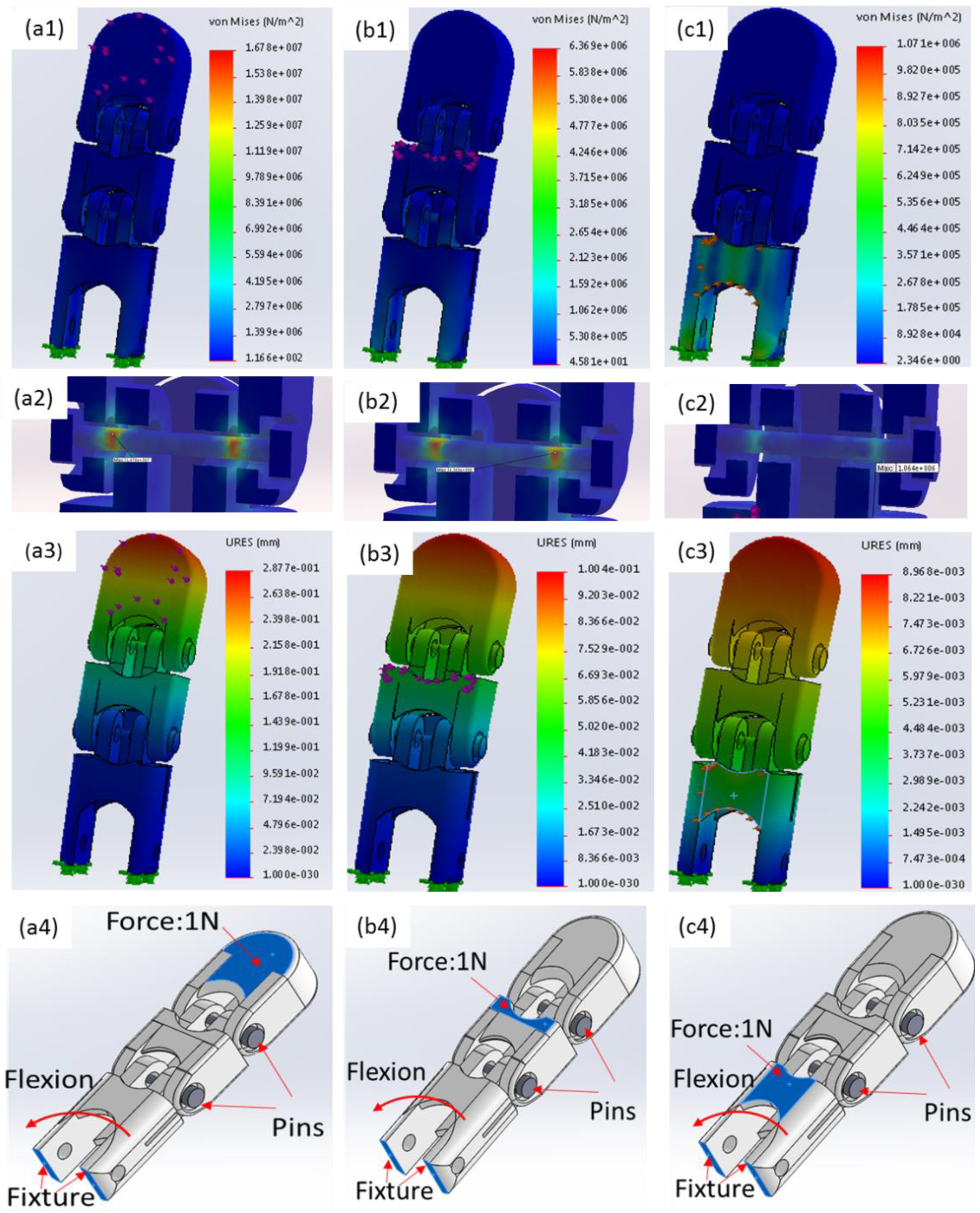
4.2. Stress Simulation of Robotic Finger
4.3. DH Parameters and Workspace Analysis

5. Experiments
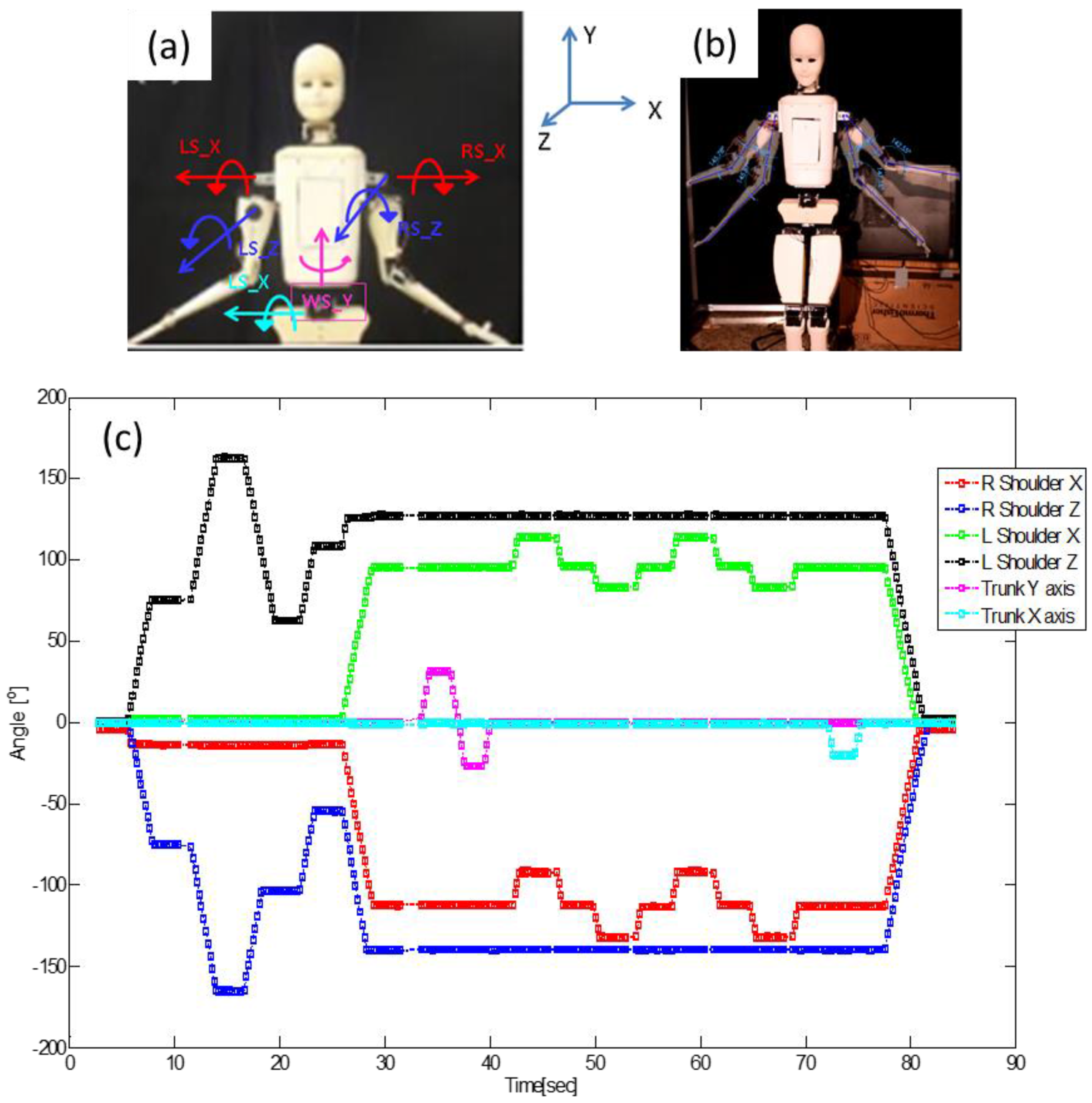
5.1. Angular Position and Speed of the Arm

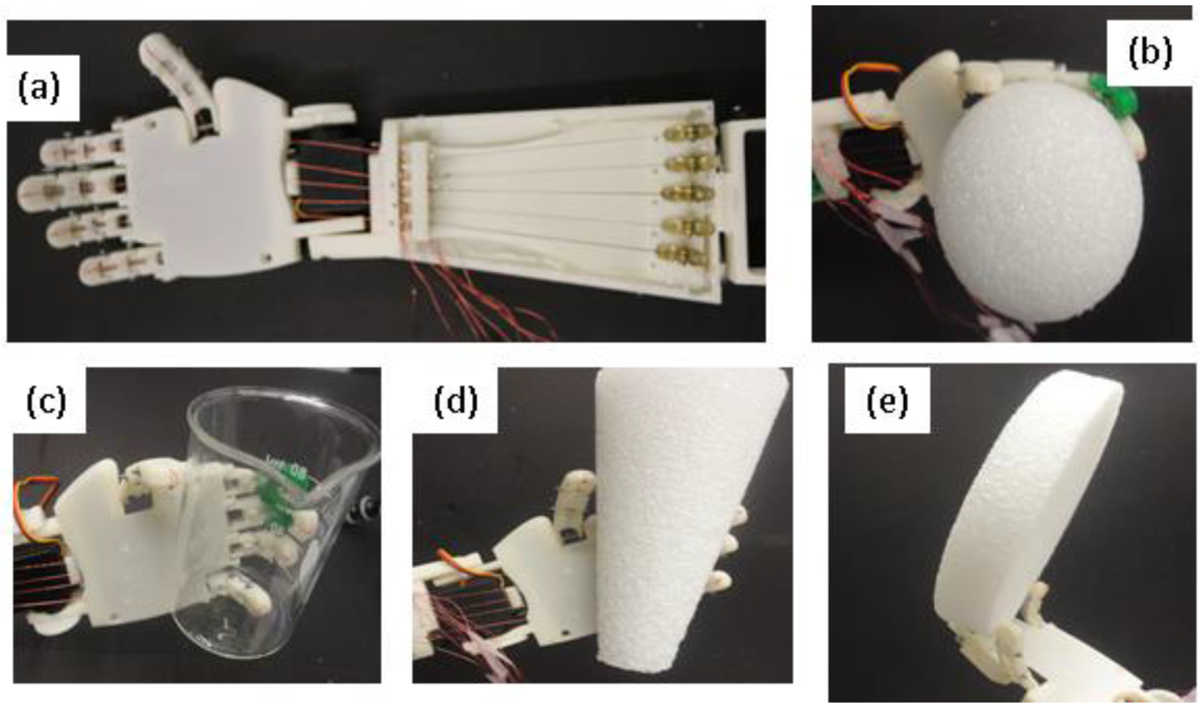
5.2. Grasping Capabilities


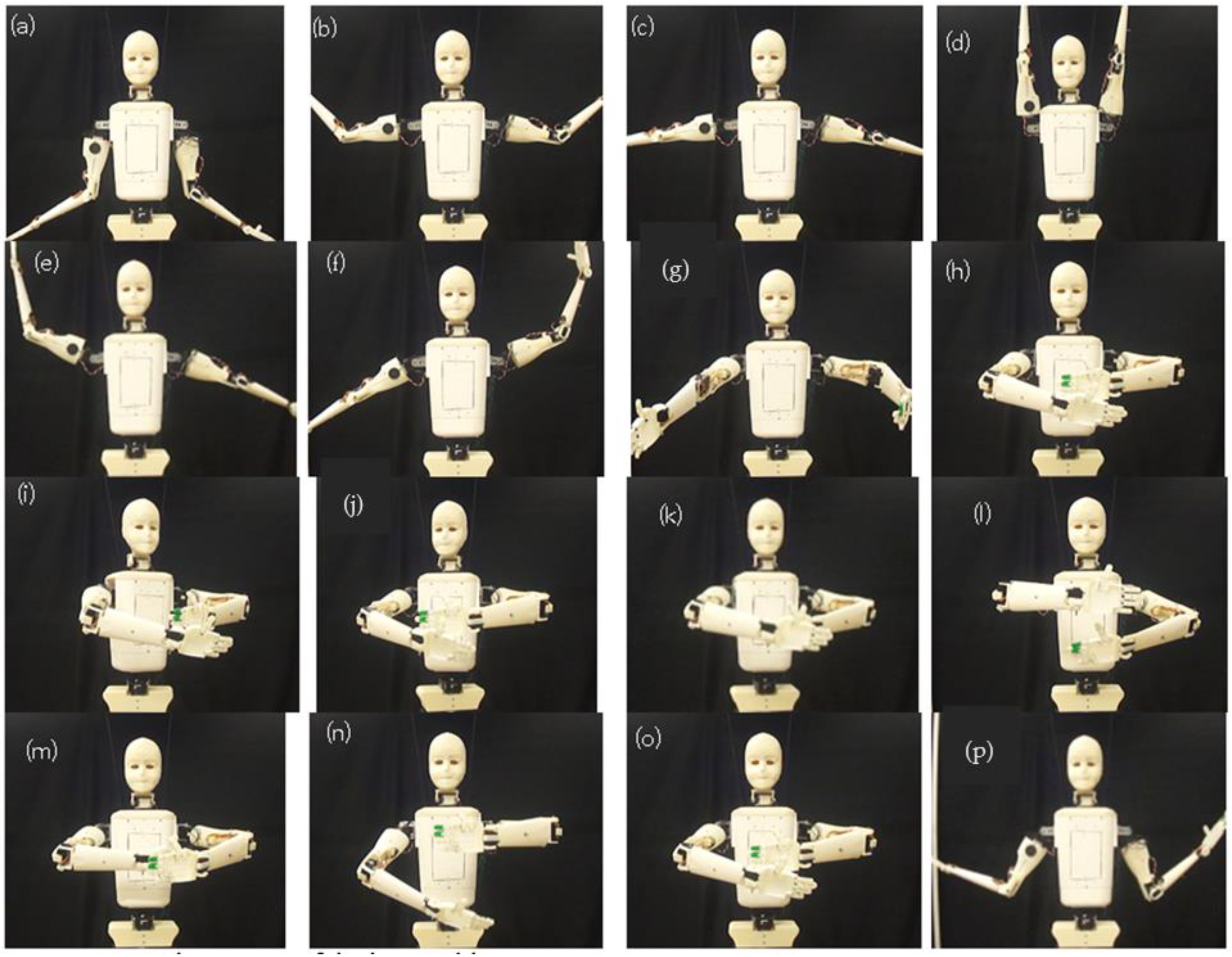
5.3. Various Poses
6. Discussions and Applications
6.1. Discussion
6.2. Applications
7. Conclusions
Supplementary Files
Supplementary File 1Acknowledgments
Author Contributions
Conflicts of Interest
Appendix
      Dyn_eval(int *servPos)
      {
          for(int i=0;i<NUM_DYN_SERVOS;i++)
          {
                    if(i<2) continue; // Servos 0 and 1 are not present
                    else if(*(servPos+i)<*(dynPosMin+i))
                    {
                             printf("Dynamixel Servo %d 's positions is less than the min position allowed for that servo!n",i);
                             return FALSE;
                    }
                    else if(*(servPos+i)>*(dynPosMax+i))
                    {
                             printf("Dynamixel Servo %d 's positions is more than the max position allowed for that servo!n",i);
                             return FALSE;
                    }
                    else continue;
          }
          return true;
      }
      void Dyn_moveTo(int *servPos)
      {
          if(Dyn_eval(servPos))
          {
                    for(int i=0;i<NUM_DYN_SERVOS;i++)
                    {
                             if(i<2) continue; // Servos 0 and 1 are not present
                             if(servPos[i]==0)
                                      continue; // Skips if the servo position is zero
                             dxl_write_word( i, P_MOVING_SPEED_L, 56); // dxl_write_word( id, address, value);
                             dxl_write_word( i, P_GOAL_POSITION_L, servPos[i]);
                             int PresPos, CommStatus;
                             PresPos = dxl_read_word( i, P_PRESENT_POSITION_L );
                             CommStatus = dxl_get_result();
                             if( CommStatus == COMM_RXSUCCESS )
                             {
                                      printf("The Current Pos of Dynamixel Servo %d is: %dn",i, PresPos);
                             }
                             else
                             {
                                      printf("Dynamixel Servo %d ERROR:",i);
                                      PrintCommStatus(CommStatus);
                                      printf("n");
                             }
                    }
                    //Dyn_wait();
          }
          else printf("Position value entered exceeds the limit!n");
      }
      void Dyn_wait()
      {
          int Moving;
          for(int i=0;i<NUM_DYN_SERVOS;i++)
          {
                    if(i<2) continue; // Servos 0 and 1 are not present
                    printf("%d",i);
                    do
                    {
                             Moving = dxl_read_byte(i, P_MOVING );
                             printf(">"); //std::this_thread::sleep_for(std::chrono::milliseconds(x));
                    }while(Moving==1);
                    printf("n");
          }
          return;
      }
References
- Bar-Cohen, Y.; Hanson, D.; Marom, A. The Coming Robot Revolution; Springer: Berlin, Germany; Heidelberg, Germany, 2009. [Google Scholar]
- Loomis, A. Figure Drawing for All It's Worth; The Viking Press: New York, NY, USA, 1943. [Google Scholar]
- Inaba, M.; Igarashi, T.; Kagami, S.; Inoue, H. Design and implementation of a 35 D.O.F. full-body humanoid that can sit, stand up and grasp an object. Adv. Robot. 1997, 12, 1–14. [Google Scholar] [CrossRef]
- Sakagami, Y.; Watanabe, R.; Aoyama, C.; Matsunaga, S.; Higaki, N.; Fujimura, K. The intelligent asimo: System overview and integration. In Proceedings of the IEEE/RSJ International Conference on Intelligent Robots and Systems, Lausanne, Switzerland, 30 October–5 Novemver 2002; pp. 2478–2483.
- Diftler, M.A.; Mehling, J.; Abdallah, M.E.; Radford, N.A.; Bridgwater, L.B.; Sanders, A.M.; Askew, R.S.; Linn, D.M.; Yamokoski, J.D.; Permenter, F. Robonaut 2—The First Humanoid Robot in Space. In Proceedings of the 2011 IEEE International Conference on Robotics and Automation (ICRA), Shanghai, China, 14 September 2011; pp. 2178–2183.
- Kajita, S.; Kaneko, K.; Kaneiro, F.; Harada, K.; Morisawa, M.; Nakaoka, S.I.; Miura, K.; Fujiwara, K.; Neo, E.S.; Hara, I. Cybernetic human HRP-4c: A humanoid robot with human-like proportions. In Robotics Research; Springer: Berlin, Germany; Heidelberg, Germany, 2011; pp. 301–314. [Google Scholar]
- Bridgwater, L.B.; Ihrke, C.; Diftler, M.A.; Abdallah, M.E.; Radford, N.A.; Rogers, J.; Yayathi, S.; Askew, R.S.; Linn, D.M. The robonaut 2 hand-designed to do work with tools. In Proceedings of the 2012 IEEE International Conference on Robotics and Automation (ICRA), Saint Paul, MN, USA, 14–18 May 2012; pp. 3425–3430.
- Kwon, W.; Kim, H.K.; Park, J.K.; Roh, C.H.; Lee, J.; Park, J.; Kim, W.K.; Roh, K. Biped humanoid robot mahru III. In Proceedings of the 2007 7th IEEE-RAS International Conference on Humanoid Robots, Pittsburgh, PA, USA, 29 November–1 December 2007; pp. 583–588.
- Robot Scientist Pushes Limits of Virtual Reality. Available online: http://www.koreaherald.com/view.php?ud= 20131225000122 (accessed on 30 July 2014).
- Yamasaki, F.; Matsui, T.; Miyashita, T.; Kitano, H. Pino the humanoid: A basic architecture. In Robocup 2000: Robot Soccer World Cup IV; Springer: Berlin, Germany; Heidelberg, Germany, 2001; pp. 269–278. [Google Scholar]
- Ambrose, R.O.; Savely, R.T.; Goza, S.M.; Strawser, P.; Diftler, M.A.; Spain, I.; Radford, N. Mobile manipulation using NASA’s robonaut. In Proceedings of the IEEE International Conference on Robotics and Automation, New Orleans, LA, USA, 26 April–1 May 2004; pp. 2104–2109.
- Endo, G.; Nakanishi, J.; Morimoto, J.; Cheng, G. Experimental studies of a neural oscillator for biped locomotion with qrio. In Proceedings of the IEEE International Conference on Robotics and Automation, Barcelona, Spain, 18–22 April 2005; pp. 596–602.
- Rehnmark, F.; Ambrose, R.O.; Kennedy, B.; Diftler, M.; Mehling, J.; Bridgwater, L.; Radford, N.; Goza, S.M.; Culbert, C. Innovative robot archetypes for in-space construction and maintenance. In Proceedings of the Conference on Human/Robotic Technology and the National Vision for Space Exploration, Albuquerque, NM, USA, 13–17 February 2005.
- Kubota, N.; Yorita, A. Structured learning for partner robots based on natural communication. In Proceedings of the IEEE Conference on Soft Computing in Industrial Applications, Muroran, Japan, 25–27 June 2008; pp. 303–308.
- Mizuuchi, I.; Yoshikai, T.; Sodeyama, Y.; Nakanishi, Y.; Miyadera, A.; Yamamoto, T.; Niemela, T.; Hayashi, M.; Urata, J.; Namiki, Y. Development of musculoskeletal humanoid kotaro. In Proceedings of the IEEE Conference on Robotics and Automation, Orlando, FL, USA, 15–19 May 2006; pp. 82–87.
- Davis, D.R.; Mehling, J.S.; Parsons, A.H.; Permenter, F.N.; Radford, N.A. Method and Apparatus for Electromagnetically Braking a Motor. Google Patents US8067909 B2, 29 November 2011. [Google Scholar]
- Lapeyre, M.; Rouanet, P.; Oudeyer, P.Y. Poppy: A new bio-inspired humanoid robot platform for biped locomotion and physical human-robot interaction. In Proceedings of the 6th International Symposium on Adaptive Motion in Animals and Machines, Darmstadt, Germany, 11–14 March 2013.
- Oh, J.H.; Hanson, D.; Kim, W.S.; Han, I.Y.; Kim, J.Y.; Park, I.W. Design of android type humanoid robot Albert HUBO. In Proceedings of the IEEE/RSJ International Conference on Intelligent Robots and Systems, Beijing, China, 9–15 October 2006; pp. 1428–1433.
- Ishiguro, H.; Nishio, S. Building artificial humans to understand humans. J. Artif. Organs 2007, 10, 133–142. [Google Scholar] [CrossRef] [PubMed]
- Ahn, H.S.; Lee, D.W.; Choi, D.; Lee, D.Y.; Hur, M.; Lee, H. Appropriate emotions for facial expressions of 33-DOFs android head ever-4 h33. In Proceedings of the IEEE International Workshop on RO-MAN, Paris, France, 9–13 September 2012; pp. 1115–1120.
- Diftler, M.; Ahlstrom, T.; Ambrose, R.; Radford, N.; Joyce, C.; De La Pena, N.; Parsons, A.; Noblitt, A. Robonaut 2—Initial activities on-board the iss. In Proceedings of the IEEE Aerospace Conference, Big Sky, MT, USA, 3–10 March 2012; pp. 1–12.
- Ranatunga, I.; Beltran, M.; Torres, N.A.; Bugnariu, N.; Patterson, R.M.; Garver, C.; Popa, D.O. Human-robot upper body gesture imitation analysis for autism spectrum disorders. In Social Robotics; Springer: Berlin, Germany; Heidelberg, Germany, 2013; pp. 218–228. [Google Scholar]
- Davis, D.R.; Radford, N.A.; Permenter, F.N.; Valvo, M.C.; Askew, R.S. Integrated High-Speed Torque Control System for a Robotic Joint. Google Patents US8442684 B2, 14 May 2013. [Google Scholar]
- Shimada, M.; Minato, T.; Itakura, S.; Ishiguro, H. Evaluation of android using unconscious recognition. In Proceedings of the 2006 6th IEEE-RAS International Conference on Humanoid Robots, Genova, Switzerland, 4–6 December 2006; pp. 157–162.
- Davis, D.R.; Permenter, F.N.; Radford, N.A. System and Method for Calibrating a Rotary Absolute Position Sensor. Google Patents US8250901 B2, 28 August 2012. [Google Scholar]
- Tsagarakis, N.G.; Metta, G.; Sandini, G.; Vernon, D.; Beira, R.; Becchi, F.; Righetti, L.; Santos-Victor, J.; Ijspeert, A.J.; Carrozza, M.C.; et al. Icub: The design and realization of an open humanoid platform for cognitive and neuroscience research. Adv. Robot. 2007, 21, 1151–1175. [Google Scholar] [CrossRef]
- Tsai, M.J.; Wu, C.T. Study of mandible reconstruction using a fibula flap with application of additive manufacturing technology. BioMed. Eng. Online 2014, 13, 57. [Google Scholar] [CrossRef] [PubMed]
- Dautenhahn, K.; Nehaniv, C.L.; Walters, M.L.; Robins, B.; Kose-Bagci, H.; Mirza, N.A.; Blow, M. Kaspar—A minimally expressive humanoid robot for human-robot interaction research. Appl. Bionics Biomech. 2009, 6, 369–397. [Google Scholar] [CrossRef]
- Kumar, P.K.; Lagoudas, D.C.; Zanca, K.J.; Lagoudas, M.Z. Thermomechanical characterization of high temperature sma actuators. In Proceedings of the International Society for Optics and Photonics, Smart Structures and Materials, San Diego, CA, USA, 26 Feburary 2006; pp. 12–17.
- Pfeifer, R.; Iida, F.; Lungarella, M. Cognition from the bottom up: On biological inspiration, body morphology, and soft materials. Trends Cognit. Sci. 2014, 18, 404–413. [Google Scholar] [CrossRef] [PubMed]
- Nakanishi, Y.; Ohta, S.; Shirai, T.; Asano, Y.; Kozuki, T.; Kakehashi, Y.; Mizoguchi, H.; Kurotobi, T.; Motegi, Y.; Sasabuchi, K. Design approach of biologically-inspired musculoskeletal humanoids. Int. J. Adv. Robot. Syst. 2013, 10. [Google Scholar] [CrossRef]
- Lee, D.D.; Yi, S.J.; McGill, S.; Zhang, Y.; Behnke, S.; Missura, M.; Schulz, H.; Hong, D.; Han, J.; Hopkins, M. Robocup 2011 humanoid league winners. In Robocup 2011: Robot Soccer World Cup XV; Springer: Berlin, Germany; Heidelberg, Germany, 2012; pp. 37–50. [Google Scholar]
- Giszter, S.F.; Moxon, K.A.; Rybak, I.; Chapin, J.K. A neurobiological perspective on humanoid robot design. IEEE Intell. Syst. 2000, 15, 64–69. [Google Scholar] [CrossRef]
- Cheng, G.; Hyon, S.H.; Morimoto, J.; Ude, A.; Hale, J.G.; Colvin, G.; Scroggin, W.; Jacobsen, S.C. Cb: A humanoid research platform for exploring neuroscience. Adv. Robot. 2007, 21, 1097–1114. [Google Scholar] [CrossRef]
- Schwarz, M.; Pastrana, J.; Allgeuer, P.; Schreiber, M.; Schueller, S.; Missura, M.; Behnke, S. Humanoid teensize open platform nimbro-op. In Proceedings of the 17th RoboCup International Symposium, Eindhoven, The Netherlands, 30 June 2013.
- Kozuki, T.; Motegi, Y.; Shirai, T.; Asano, Y.; Urata, J.; Nakanishi, Y.; Okada, K.; Inaba, M. Design of upper limb by adhesion of muscles and bones—Detail human mimetic musculoskeletal humanoid kenshiro. In Proceedings of the IEEE/RSJ International Conference on Intelligent Robots and Systems, Tokyo, Japan, 3–7 November 2013; pp. 935–940.
- Byko, M. Personification: The Materials Science and Engineering of Humanoid Robots. Available online: http://www.tms.org/pubs/journals/JOM/0311/Byko-0311.html (accessed on 20 October 2015).
- Park, I.W.; Kim, J.Y.; Lee, J.; Oh, J.H. Mechanical design of the humanoid robot platform, HUBO. Adv. Robot. 2007, 21, 1305–1322. [Google Scholar] [CrossRef]
- Robotis. Available online: http://www.robotis.com/xe/ (accessed on 7 April 2014).
- Hara, Y. Sony’s Qrio Robot Hits the Ground Running. Available online: http://www.eetimes.com/document.asp?doc_id= 1147759 (accessed on 20 October 2015).
- Asimo Technical Information. Available online: http://asimo.honda.com/downloads/pdf/asimo-technical-information.pdf (accessed on 20 October 2015).
- Legged Locomotion. Available online: http://www-clmc.usc.edu/Research/LeggedLocomotion (accessed on 20 October 2015).
- Geppert, L. Qrio: The Robot That Could. Available online: http://spectrum.ieee.org/robotics/robotics-software/qrio-the-robot-that-could (accessed on 20 October 2015).
- Narioka, K.; Hosoda, K. Designing synergistic walking of a whole-body humanoid driven by pneumatic artificial muscles: An empirical study. Adv. Robot. 2008, 22, 1107–1123. [Google Scholar] [CrossRef]
- Dzahir, M.A.M.; Yamamoto, S.I. Recent trends in lower-limb robotic rehabilitation orthosis: Control scheme and strategy for pneumatic muscle actuated gait trainers. Robotics 2014, 3, 120–148. [Google Scholar] [CrossRef]
- Van Ninhuijs, B.; van der Heide, L.; Jansen, J.; Gysen, B.; van der Pijl, D.; Lomonova, E. Overview of actuated arm support systems and their applications. Actuators 2013, 2, 86–110. [Google Scholar] [CrossRef]
- Tadesse, Y. Actuation technologies for humanoid robots with facial expressions (hrwfe). Trans. Control Mech. Syst. 2013, 2, 1–10. [Google Scholar]
- Tadesse, Y. Actuation technologies suitable for humanoid robots. In Proceedings of the ASME 2012 International Mechanical Engineering Congress and Exposition, Houston, TX, USA, 9–15 November 2012; American Society of Mechanical Engineers: New York, NY, USA, 2012; pp. 1–10. [Google Scholar]
- Tadesse, Y. Electroactive polymer and shape memory alloy actuators in biomimetics and humanoids. In Proceedings of the SPIE Smart Structures and Materials+ Nondestructive Evaluation and Health Monitoring, San Diego, CA, USA, 12–13 March 2013; pp. 9–12.
- Tadesse, Y.; Hong, D.; Priya, S. Twelve degree of freedom baby humanoid head using shape memory alloy actuators. J. Mech. Robot. 2011, 3, 011008. [Google Scholar] [CrossRef]
- Jovanovic, K.; Potkonjak, V.; Holland, O. Dynamic modeling of an anthropomimetic robot in contact tasks. Adv. Robot. 2014, 28, 793–806. [Google Scholar]
- Nagakubo, A.; Kuniyoshi, Y.; Cheng, G. The etl-humanoid system—A high-performance full-body humanoid system for versatile real-world interaction. Adv. Robot. 2003, 17, 149–164. [Google Scholar] [CrossRef]
- Hari Krishnan, R.; Vallikannu, A. A semi-minimalistic approach to humanoid design. Int. J. Sci. Res. Publ. 2012, 2, 1–6. [Google Scholar]
- Shome, S.N.; Basu, J.; Sinha, G.P. Proceedings of the National Conference on Advanced Manufacturing & Robotics; Allied Publishers: New Delhi, India, 2004. [Google Scholar]
- Grunberg, D.; Ellenberg, R.; Kim, Y.; Oh, P. From Robonova to HUBO: Platforms for robot dance. In Progress in Robotics; Kim, J.H., Ge, S., Vadakkepat, P., Jesse, N., al Manum, A., Puthusserypady, K.S., Rückert, U., Sitte, J., Witkowski, U., Nakatsu, R., et al., Eds.; Springer: Berlin, Germany; Heidelberg, Germany, 2009; Volume 44, pp. 19–24. [Google Scholar]
- Zhou, C.; Yue, P.K. Robo-erectus: A low-cost autonomous humanoid soccer robot. Adv. Robot. 2004, 18, 717–720. [Google Scholar] [CrossRef]
- Oh, K.; Kim, J.; Kim, M. Development of humanoid robot design process-focused on the concurrent engineering based humanoid robot design. In Proceedings of the IASDR Conference, Yunlin, Taiwan, 11–14 November 2005.
- Okumura, Y.; Tawara, T.; Furuta, T.; Endo, K.; Shimizu, M.; Shimomura, M.; Kitano, H. Morph3: A compact-size humanoid robot system capable of acrobatic behavior. Adv. Robot. 2004, 18, 699–710. [Google Scholar] [CrossRef]
- Zhu, C.; Kawamura, A. Development of biped robot mari-3 for jumping. Adv. Robot. 2010, 24, 1661–1675. [Google Scholar] [CrossRef]
- Stasse, O.; Verrelst, B.; Wieber, P.B.; Vanderborght, B.; Evrard, P.; Kheddar, A.; Yokoi, K. Modular architecture for humanoid walking pattern prototyping and experiments. Adv. Robot. 2008, 22, 589–611. [Google Scholar] [CrossRef]
- Kamide, H.; Kawabe, K.; Shigemi, S.; Arai, T. Development of a psychological scale for general impressions of humanoid. Adv. Robot. 2013, 27, 3–17. [Google Scholar] [CrossRef]
- Lund, H.H.; Pagliarini, L. Modular behavior-based control for team humanoids. Adv. Robot. 2004, 18, 659–676. [Google Scholar] [CrossRef]
- Hashimoto, K.; Takezaki, Y.; Lim, H.O.; Takanishi, A. Walking stabilization based on gait analysis for biped humanoid robot. Adv. Robot. 2013, 27, 541–551. [Google Scholar] [CrossRef]
- Ha, I.; Tamura, Y.; Asama, H. Development of open platform humanoid robot darwin-op. Adv. Robot. 2013, 27, 223–232. [Google Scholar] [CrossRef]
- Hackel, M.; Schwope, S.; Fritsch, J.; Wrede, B.; Sagerer, G. Designing a sociable humanoid robot for interdisciplinary research. Adv. Robot. 2006, 20, 1219–1235. [Google Scholar] [CrossRef]
- Yu, Z.; Ma, G.; Huang, Q. Modeling and design of a humanoid robotic face based on an active drive points model. Adv. Robot. 2014, 28, 379–388. [Google Scholar] [CrossRef]
- Wu, L.; Jung de Andrade, M.; Rome, R.S.; Baughman, R.H.; Tadesse, Y. Nylon-muscle-actuated robotic finger. In Proceedings of the SPIE Biological-Inspired Systems and Bio-MEMS, San Digeo, CA, USA, 2 April 2015.
- Gibson, I.; Rosen, D.W.; Stucker, B. Additive Manufacturing Technologies: Rapid Prototyping to Direct Digital Manufacturing; Springer: Berlin, Germany; Heidelberg, Germany, 2009. [Google Scholar]
- Boothroyd, G.; Dewhurst, P.; Knight, W.A. Product Design for Manufacture and Assembly, 3rd ed.; Taylor & Francis: Boca Raton, FL, USA, 2010. [Google Scholar]
- Ulrich, K.T.; Eppinger, S.D. Product Design and Development; McGraw-Hill: New York, NY, USA, 2012. [Google Scholar]
- Snyder, R.G.; Spencer, M.L.; Owings, C.L.; Schneider, L.W. Anthropometry of US Infants and Children. SAE Tech. Pap. 1975, 750423. [Google Scholar] [CrossRef]
- Tedeschi, F.; Carbone, G. Design issues for hexapod walking robots. Robotics 2014, 3, 181–206. [Google Scholar] [CrossRef]
- Tadesse, Y.; Subbarao, K.; Priya, S. Realizing a humanoid neck with serial chain four-bar mechanism. J. Intell. Mater. Syst. Struct. 2010, 21, 1169–1191. [Google Scholar] [CrossRef]
- Wu, L.; Tadesse, Y. Humanoid robot hand with sma actuators and servo motors. In Proceedings of the ASME 2014 International Mechanical Engineering Congress and Exposition, Montreal, QC, Canada, 14–20 November 2014; American Society of Mechanical Engineers: New York, NY, USA, 2014. [Google Scholar]
- Abs Plus-p430, Production-Grade Thermoplastic for Design Series 3d Printers. Available online: http://usglobalimages.stratasys.com/Main/Files/Material_Spec_Sheets/MSS_FDM_ABSplusP430.pdf (accessed on 4 November 2015).
- Liu, Z.; Fang, S.; Moura, F.; Ding, J.; Jiang, N.; Di, J.; Zhang, M.; Lepró, X.; Galvão, D.; Haines, C. Hierarchically buckled sheath-core fibers for superelastic electronics, sensors and muscles. Science 2015, 349, 400–404. [Google Scholar] [CrossRef] [PubMed]
- Leigh, S.J.; Bradley, R.J.; Purssell, C.P.; Billson, D.R.; Hutchins, D.A. A simple, low-cost conductive composite material for 3d printing of electronic sensors. PLoS ONE 2012, 7, e49365. [Google Scholar] [CrossRef] [PubMed]
- Lewis, F.L.; Dawson, D.M.; Abdallah, C.T. Robot Manipulator Control: Theory and Practice; Taylor & Francis: Boca Raton, FL, USA, 2003. [Google Scholar]
- Kanniah, J.; Ercan, F.; Calderon, C.A.A. Practical Robot Design: Game Playing Robots; Taylor & Francis: Boca Raton, FL, USA, 2013. [Google Scholar]
- Tadesse, Y.; Thayer, N.; Priya, S. Tailoring the response time of shape memory alloy wires through active cooling and pre-stress. J. Intell. Mater. Syst. Struct. 2009, 21, 19–40. [Google Scholar] [CrossRef]
- Tadesse, Y.; Villanueva, A.; Haines, C.; Novitski, D.; Baughman, R.; Priya, S. Hydrogen-fuel-powered bell segments of biomimetic jellyfish. Smart Mater. Struct. 2012, 21, 045013. [Google Scholar] [CrossRef]
- Joh, H.I.; Ha, T.J.; Hwang, S.Y.; Kim, J.H.; Chae, S.H.; Cho, J.H.; Prabhuram, J.; Kim, S.K.; Lim, T.H.; Cho, B.K. A direct methanol fuel cell system to power a humanoid robot. J. Power Sources 2010, 195, 293–298. [Google Scholar] [CrossRef]
- Maeno, T.; Hino, T. Miniature five-fingered robot hand driven by shape memory alloy actuators. In Proceedings of the 12th IASTED International Conference on Robotics and Applications, Honolulu, HI, USA, 14–16 August 2006; pp. 174–179.
- Rodrigue, H.; Wei, W.; Bhandari, B.; Ahn, S.H. Fabrication of wrist-like sma-based actuator by double smart soft composite casting. Smart Mater. Struct. 2015, 24, 125003. [Google Scholar] [CrossRef]
- Majima, S.; Kodama, K.; Hasegawa, T. Modeling of shape memory alloy actuator and tracking control system with the model. IEEE Trans. Control Syst. Technol. 2001, 9, 54–59. [Google Scholar] [CrossRef]
- Ma, N.; Song, G.; Lee, H. Position control of shape memory alloy actuators with internal electrical resistance feedback using neural networks. Smart Mater. Struct. 2004, 13, 777. [Google Scholar] [CrossRef]
- Grant, D.; Hayward, V. Variable structure control of shape memory alloy actuators. IEEE Control Syst. 1997, 17, 80–88. [Google Scholar] [CrossRef]
- Elahinia, M.H.; Ashrafiuon, H. Nonlinear control of a shape memory alloy actuated manipulator. J. Vib. Acoust. 2002, 124, 566–575. [Google Scholar] [CrossRef]
- Song, G.; Chaudhry, V.; Batur, C. Precision tracking control of shape memory alloy actuators using neural networks and a sliding-mode based robust controller. Smart Mater. Struct. 2003, 12, 223–231. [Google Scholar] [CrossRef]
- Spong, M.W.; Hutchinson, S.; Vidyasagar, M. Robot Modeling and Control; Wiley: New York, NY, USA, 2006; Volume 3. [Google Scholar]
- Tadesse, Y.; Priya, S. Graphical facial expression analysis and design method: An approach to determine humanoid skin deformation. J. Mech. Robot. 2012, 4, 021010. [Google Scholar] [CrossRef]
- Dahl, T.S.; Boulos, M.N.K. Robots in health and social care: A complementary technology to home care and telehealthcare? Robotics 2013, 3, 1–21. [Google Scholar] [CrossRef]
© 2016 by the authors; licensee MDPI, Basel, Switzerland. This article is an open access article distributed under the terms and conditions of the Creative Commons by Attribution (CC-BY) license (http://creativecommons.org/licenses/by/4.0/).
Share and Cite
Wu, L.; Larkin, M.; Potnuru, A.; Tadesse, Y. HBS-1: A Modular Child-Size 3D Printed Humanoid. Robotics 2016, 5, 1. https://doi.org/10.3390/robotics5010001
Wu L, Larkin M, Potnuru A, Tadesse Y. HBS-1: A Modular Child-Size 3D Printed Humanoid. Robotics. 2016; 5(1):1. https://doi.org/10.3390/robotics5010001
Chicago/Turabian StyleWu, Lianjun, Miles Larkin, Akshay Potnuru, and Yonas Tadesse. 2016. "HBS-1: A Modular Child-Size 3D Printed Humanoid" Robotics 5, no. 1: 1. https://doi.org/10.3390/robotics5010001
APA StyleWu, L., Larkin, M., Potnuru, A., & Tadesse, Y. (2016). HBS-1: A Modular Child-Size 3D Printed Humanoid. Robotics, 5(1), 1. https://doi.org/10.3390/robotics5010001