1. Introduction
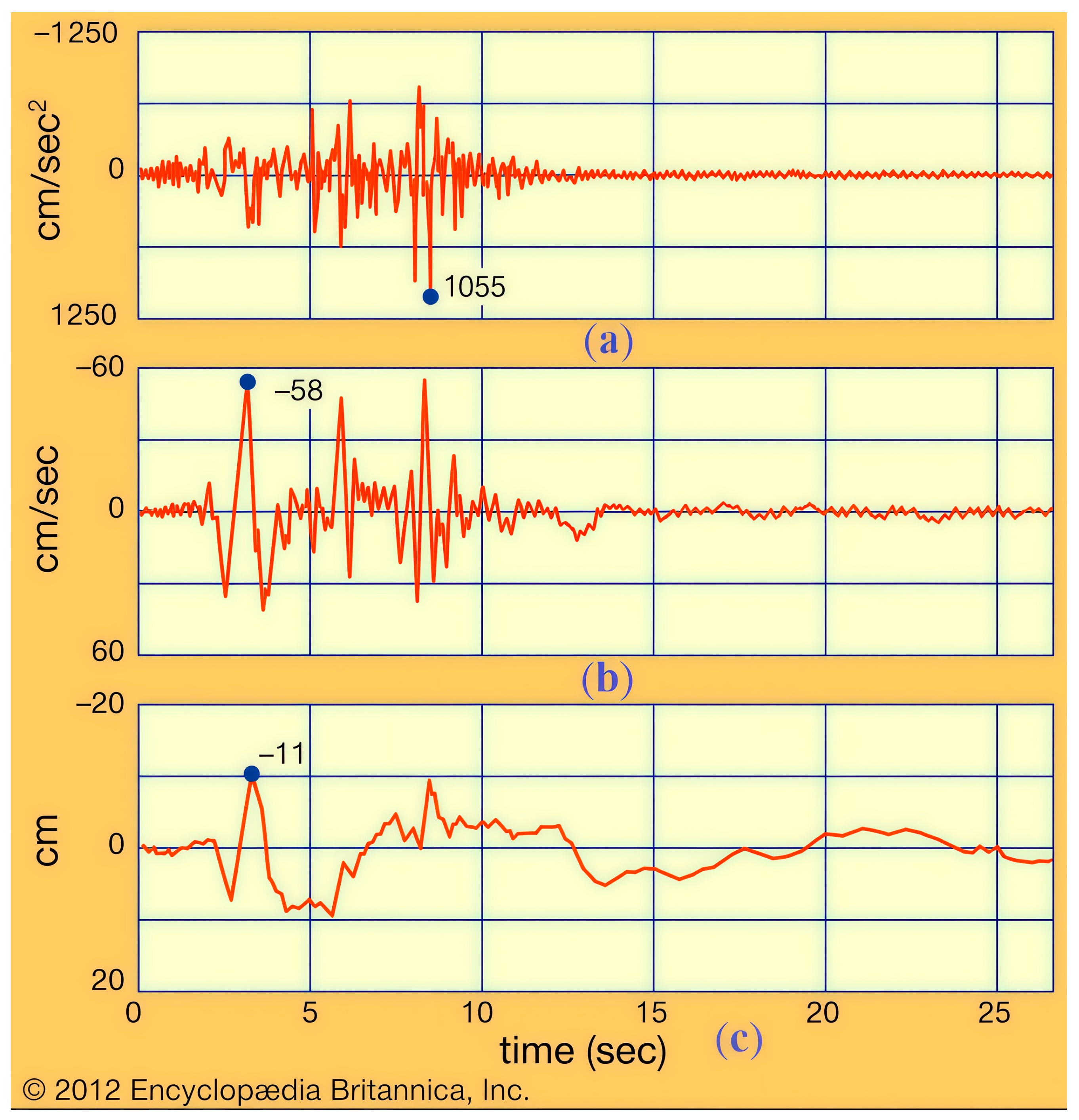
Earthquakes occur unexpectedly and produce catastrophic destruction. After 10–20 s of ground vibrations, tremors intensify, which leads to the destruction of buildings and structures. Due to the increasing construction of tall buildings and industrial facilities, scientists and engineers have paid a great deal of attention to the research of seismic waves that cause long-period ground motion [
1]. This type of seismic wave occurs during very strong earthquakes and causes periodic motions within one to ten seconds. These waves propagate over long distances over the earth’s surface and excite low-frequency structural vibrations in multi-story buildings, which cause serious damage to the people or objects inside them.
Due to the fact that an earthquake cannot be predicted, the simulation of earthquakes using earthquake simulators is of great importance. An earthquake simulator is a device that reproduces the seismic waves that are generated by an earthquake. It is used for experimental research on models of buildings and their foundations for seismic resistance, and even for the seismic training of people. Earthquake simulators can reproduce real seismic waves from past earthquakes. Training using earthquake simulators helps people to develop effective responses to earthquakes.
Employees of the Ministry of Emergency Situations use earthquake simulators to conduct seismic training to teach people how to behave during a real earthquake [
2]. Globally, hundreds of millions of people are exposed to a significant seismic risk of catastrophic damage. This problem is especially acute in Almaty, Republic of Kazakhstan, where the most recent earthquake, in spring 2024, caused widespread panic and exposed a complete lack of preparedness in how to feel and behave when an earthquake occurs [
3]. Earthquakes pose a danger and risk to all human beings, and everybody needs to possess the appropriate knowledge and protective measures.
The main function of an earthquake simulator is to reproduce a given earthquake seismogram along three Cartesian axes [
1]. Various types of earthquake simulators have been developed to reproduce seismic waves, including, for example, the designs in [
4,
5,
6,
7,
8,
9,
10,
11,
12,
13,
14]. In Japan, a large earthquake simulator, E-Defense [
15], was built to reproduce various seismic waves with high accuracy. The E-Defense Earthquake Simulator has a 20 m × 15 m moving platform with 14 hydraulic drives; therefore, it cannot be transported. The work [
16] presents a portable earthquake simulator, Jishin-The-Vuton 3D, which implements up-and-down motion to simulate three-dimensional ground motion during an earthquake. The disadvantage of the Jishin-The-Vuton 3D simulator is the tendency to tip over due to the small contact area of the driving system with the person sitting on it. An earthquake simulator [
17] with a vibrating platform, which is mounted on a frame, has also been developed. The platform performs reciprocating motion by means of a hydraulic drive through a system of linkages. The vibration of the platform is isolated from the frame by shock-absorbing bushings which support the lever system. Shock-absorbing feet may be used to support the frame, and the hydraulic piston is controlled by a hydraulic circuit and an electrical circuit, which provide the input to the hydraulic circuit. A feedback circuit monitors the output vibration of the platform. The disadvantage of this earthquake simulator is the complexity of the design and control due to the presence of hydraulic drives, the inability to reproduce large accelerations, low transportability, and unsuitability for the seismic training of people. Also, it does not have the ability to simulate a long-period ground motion earthquake.
Furthermore, an earthquake simulator based on the spatial parallel mechanism 4-RPS (Range Positioning System) [
18] was developed and installed on a truck. The earthquake simulator comprises a loading vehicle, a control console, a simulation room and a 4-RPS space parallel mechanism, wherein the rear part of a driving cab of the loading vehicle is provided with the control console. The simulation room is installed on a rear vehicle body of the loading vehicle through the 4-RPS space parallel mechanism, and the control console is linked with the 4-RPS space parallel mechanism to integrally form the earthquake simulator. The earthquake simulator is mobile, simple in structure, flexible and accurate in operation, and can be widely used to promote earthquake awareness in schools and communities; however, one of its disadvantages is an inability to model a long-period ground motion earthquake.
The study [
19] presents a study of the possibility of using CaPaMan (Cassino Parallel Manipulator) as an earthquake simulator. The numerical test results confirm the possibility of simulating any type of seismic motion using CaPaMan. The study [
20] presents an earthquake simulator based on CaPaMan for reproducing three-dimensional seismic motions with easy-to-use and reliable functions, and the results of experimental tests simulating a three-dimensional earthquake are shown. The study [
21] experimentally characterizes the influence of CaPaMan, which is capable of simulating seismic vibrations in three-dimensional space fairly well. The disadvantage of the CaPaMan-based earthquake simulator is the impossibility of simulating a long-period earthquake.
In [
22,
23], an earthquake simulator based on a planar cable parallel mechanism was built. Due to the use of cables, a large working space is achieved, and due to the low inertia of the moving platform, the simulator is able to simulate high accelerations. In addition, it is easy to assemble, disassemble and transport. The platform of the earthquake simulator performs a plane-parallel motion in the direction of the X and Y axes due to servomotor-induced tension in the cables, thereby simulating the longitudinal and transverse earthquake waves.
The disadvantage of this earthquake simulator is the complexity and high cost of the design due to the presence of air bearings, the unstable operation of which causes problems with platform stability. In addition, the earthquake simulator only reproduces seismic waves in the direction of the X and Y axes; however, to reproduce the real seismogram of the long-period ground motion earthquake [
1], the motion of the platform in the direction of the Z axis is necessary.
To eliminate the abovementioned disadvantages of earthquake simulators, in this paper, an earthquake simulator is designed to reproduce three-dimensional long-period ground motion during an earthquake.
The aim of this work is to present the design and prototype of an earthquake simulator that simulates a real long-period ground motion earthquake with vertical displacement, according to the earthquake seismogram. The earthquake simulator performs translational Cartesian motions. The mobile platform of the earthquake simulator moves with translational motions in the direction of the X and Y axes due to the use of cable-driven parallel robot (CDPR), and the vertical translational motion of the platform along the Z axis is performed by linear screw drives.
2. Materials and Methods
2.1. Earthquake Simulator Design
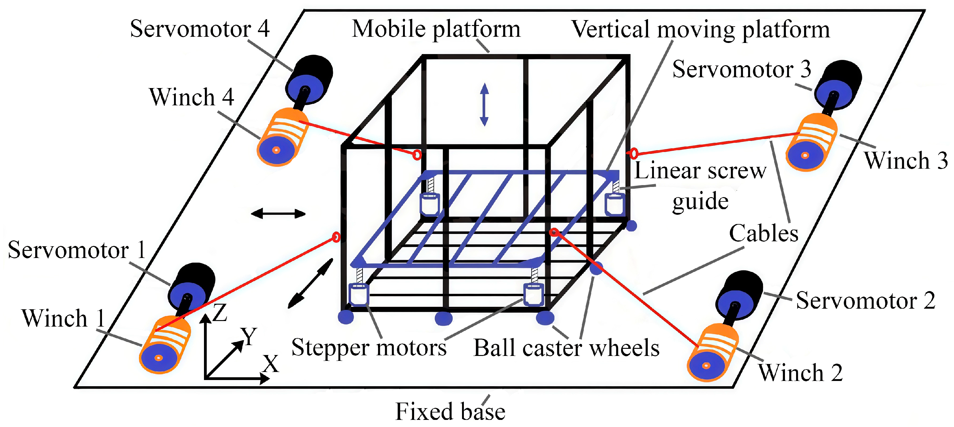
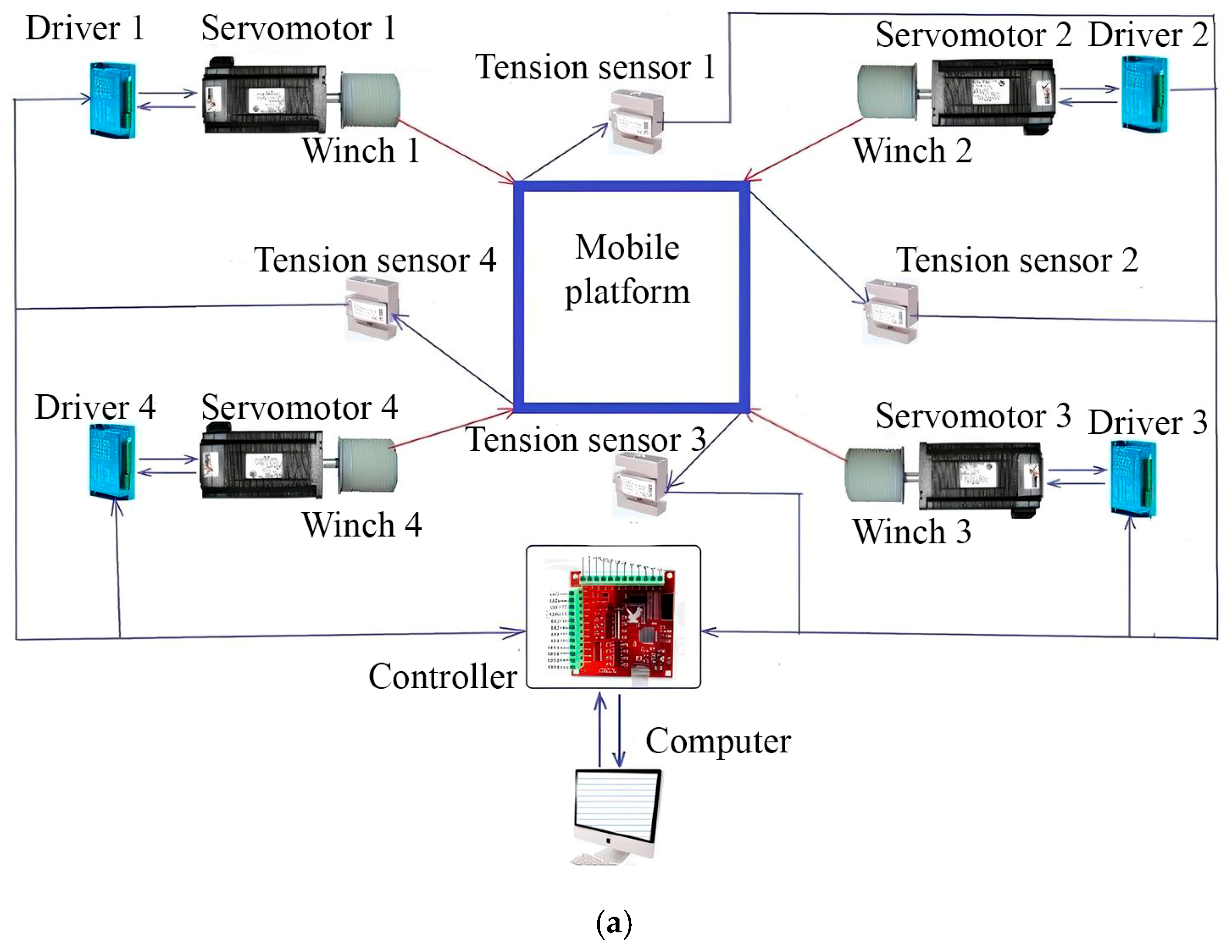
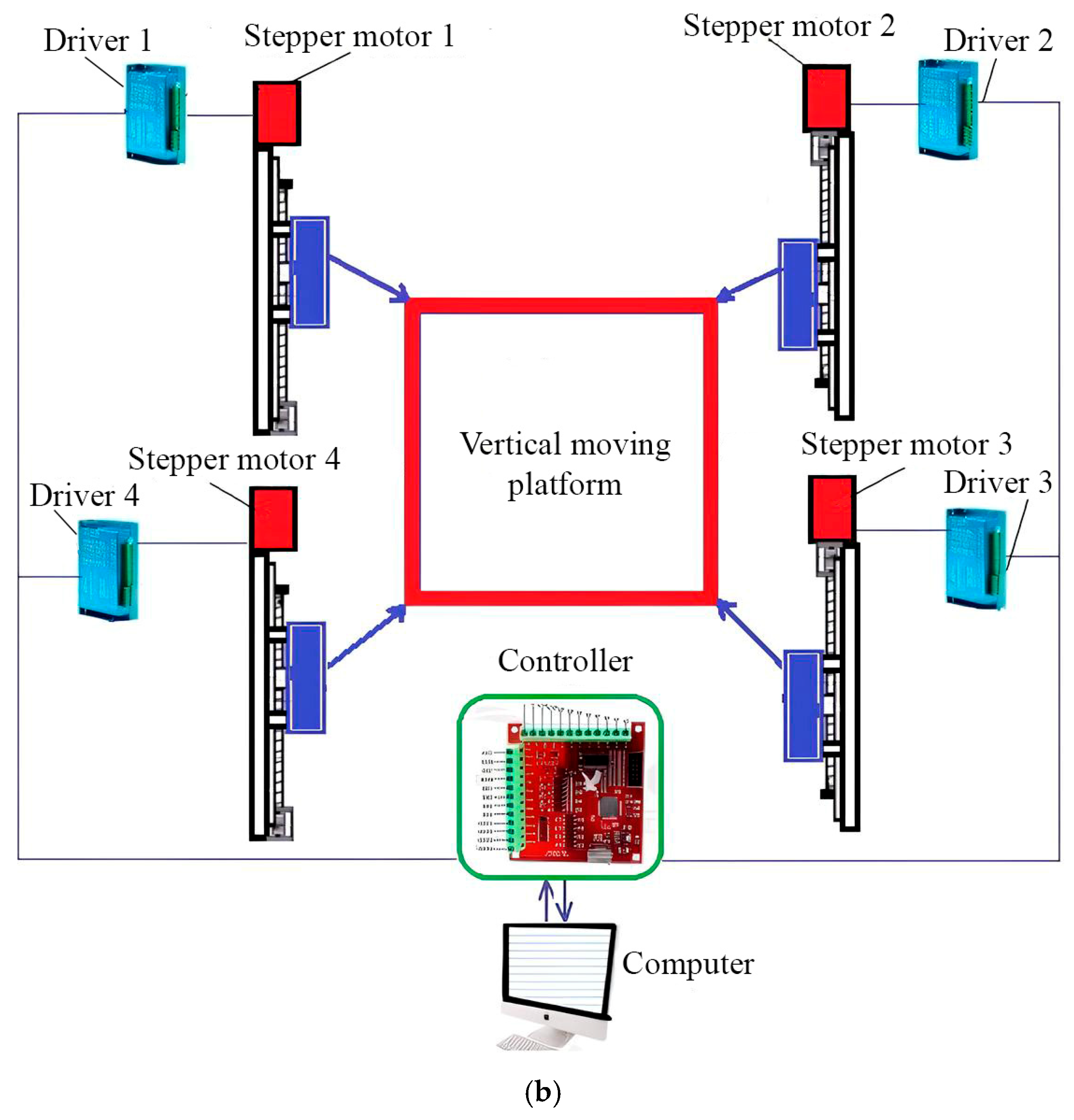
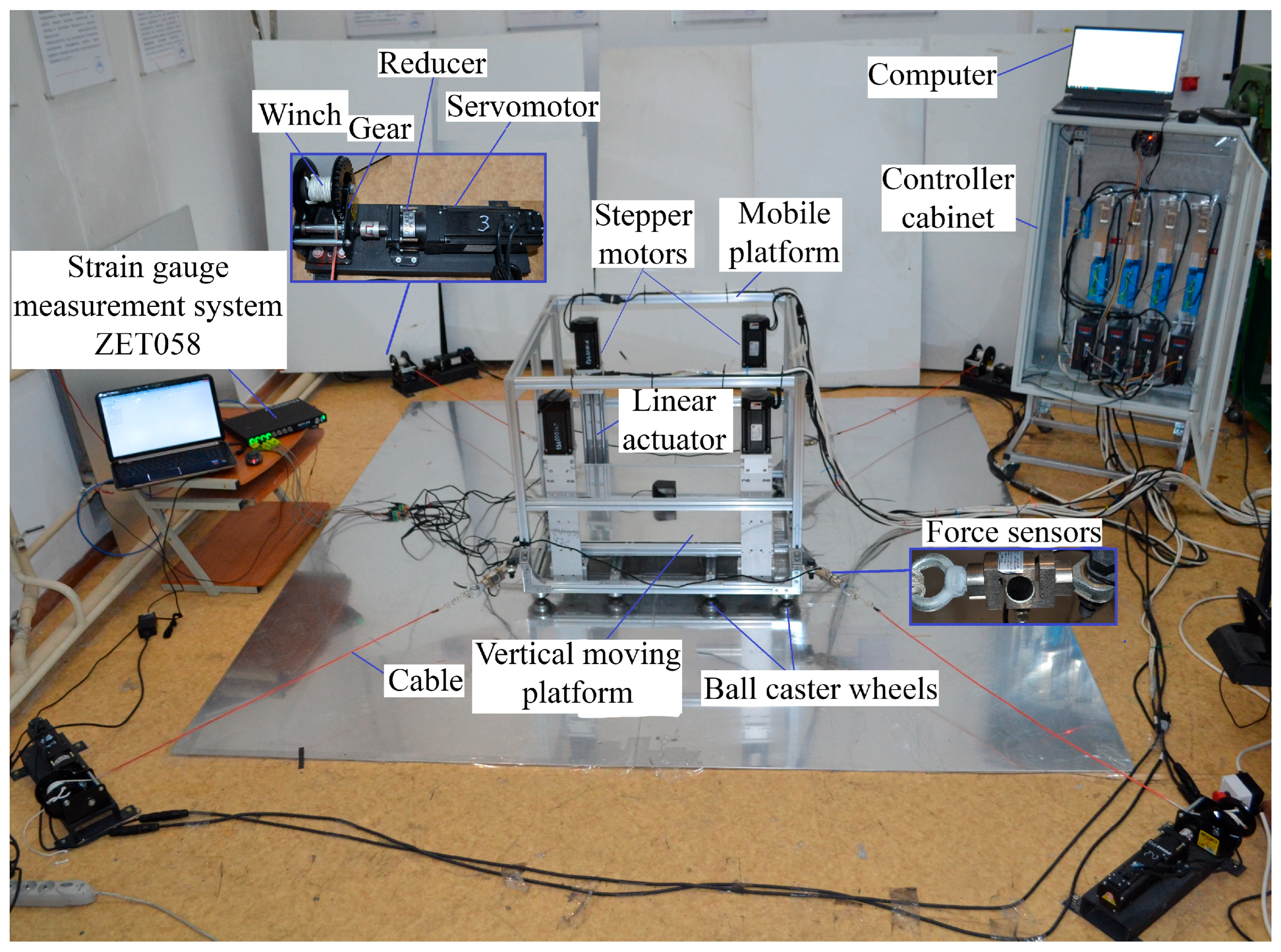
Figure 1 shows the structural scheme of the proposed earthquake simulator for reproducing three-dimensional long-period ground motion during an earthquake. To reproduce the translational motion of the mobile platform along the X and Y axes, we used a CDPR with 4 cables that are controlled by 4 servomotors. The mobile platform makes planar motions on the floor (fixed base) using nine ball caster wheels. We installed a vertical moving platform on the mobile platform to reproduce the vertical translational motion along the Z axis. The vertical moving platform moves along the Z axis on four linear screw guides with the help of four stepper motors, and for testing, the object or person is placed on it.
To reproduce a given seismogram, the earthquake simulator works as follows. The computer, using a specially designed program, issues control signals to the servomotor controllers. Servo motors begin to stretch the cables by winding and unwinding winches on drums, then motion the mobile platform horizontally along the X, Y axes, thereby simulating the longitudinal and transverse waves of an earthquake. To activate the vertical motion of the platform, four stepper motors are switched on synchronously.
The advantages of this constructive scheme of the earthquake simulator (see
Figure 1) consist in its simplicity of design and easy assembly, disassembly and transportation, and most importantly, in the possibility of realizing the vertical motion of the platform.
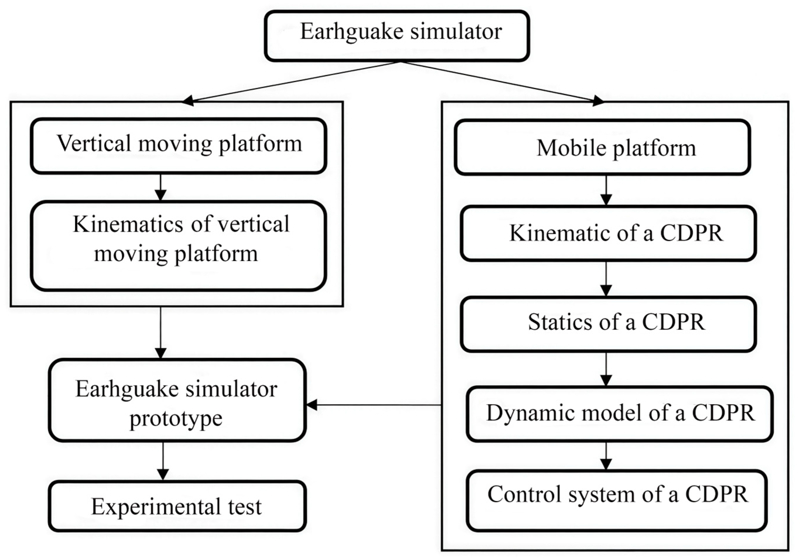
A flowchart for conducting research on an earthquake simulator was developed and is shown in
Figure 2.
2.2. Kinematics of a CDPR
Let us consider the kinematics of a 4-cable CDPR, by which the mobile platform performs translational motions in the direction of the X and Y axes. The kinematic scheme of a CDPR with four cables is shown in
Figure 3. The fixed base is determined by the plane identified by four cable drive points,
. The global coordinate system {XYZ} is set to the center of the base. The local coordinate system {xyz} is located in the geometric center P of a rectangular platform with vertices at the connection points of the cables
.
In
Figure 3,
is the position vector of point
attached to the fixed frame relative to the main coordinate system {XYZ},
is the position vector of the point
and
is the length vector of the cables relative to the main coordinate system {XYZ}. The dimensions of the fixed rectangular frame CDPR are denoted by
width and
length. The dimensions of the square mobile platform CDPR are as follows: dp—side length. In the kinematic scheme of the CDPR, it is assumed that the cables are straight and stretched. In addition, it is assumed that the vectors
and
do not depend on the position of the mobile platform; in other words, the influence of possible guide pulleys or fasteners on the platform is not taken into account.
Applying the method of closed vector loops (see
Figure 3), we obtain the following system of equations:
where the vector
is the Cartesian position of the P center of the mobile platform, relative to the global coordinate system {XYZ}. Here, the coordinate
is constant and equal to the height of the cable fastenings relative to the base because the cables act on a plane.
Equation (1) can be written as
The unit vector
in Equation (1) along the cable can be expressed as
The unit vector
is directed from the mobile platform to the fixed base, which means that the positive forces are directed in the direction that shortens the cables and thereby reduces the value of the generalized coordinate
associated with it. The coordinates of the vector
, relative to the main {XYZ} coordinate system, are given in
Table 1, referring to the mechanical design of the scheme presented in
Figure 1.
The coordinates of the vector
, relative to the local coordinate system xyz, are presented in
Table 2.
To solve the direct task of the kinematics of a CDPR, from Equation (1), we obtain 4 nonlinear equations of direct kinematics, which forms a system with redundant constraints [
24].
Here we consider cables linear springs. In general, we cannot expect the above equations to be solved exactly, but we can minimize the error, which can be interpreted as minimizing the potential energy in the pretensioned cables. Let
be the potential energy of the system,
where
is the stiffness of the
i-th cable. We assume that all cables have the same stiffness
. Then, the minimum potential energy
U of the system does not depend on the specific stiffness value
, and the direct kinematics function can be determined from the optimization problem [
24]:
where the vector
is the given number of cable lengths. The function
gives the values
, providing the minimum value in Equation (6). In solving problem (6), we obtain the coordinates of the platform with the given lengths of the cables.
2.3. Statics of a CDPR
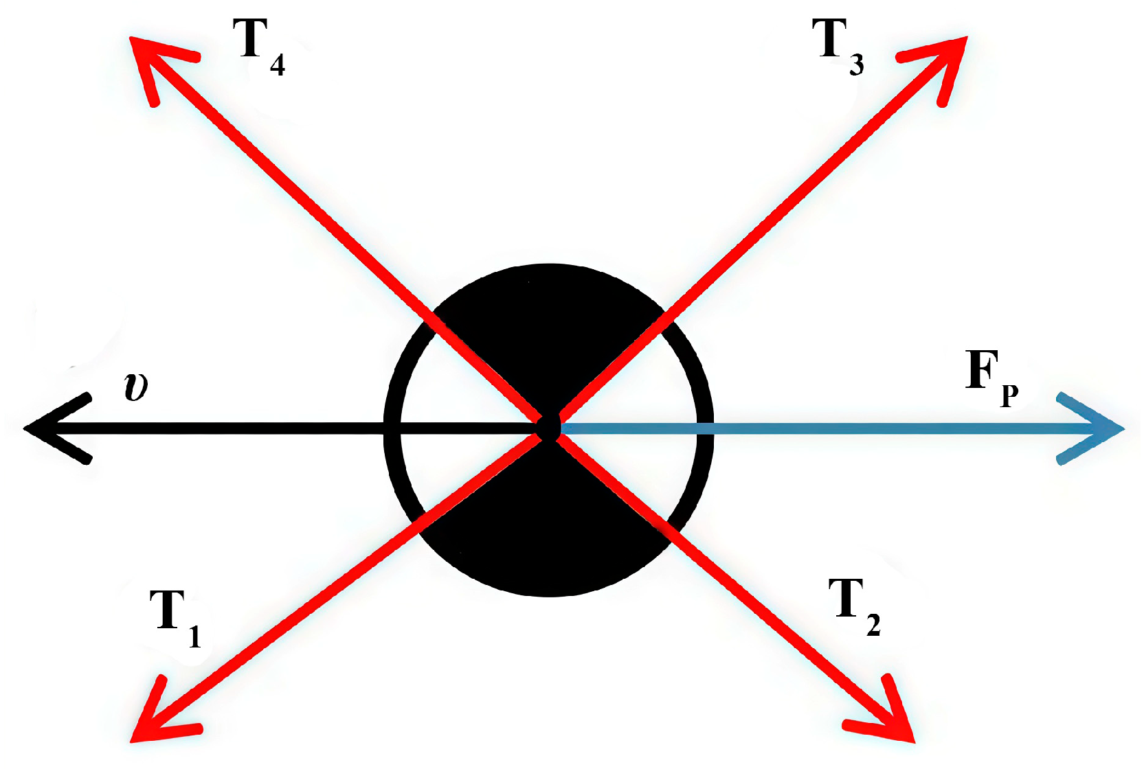
To balance the forces and moments of the movable platform of a CDPR that performs only translational motion, it is necessary to consider all the forces acting on the mobile platform, which are shown in the scheme in
Figure 4.
From
Figure 4, the equilibrium condition for the mobile platform can be expressed as
The force of the i-th cable applied to the movable platform at point can be expressed as . Here, is an external force. is the reaction from the force of gravity of a moving platform on mass .
Equation (7) can be expressed in matrix form as
where
is the CDPR structural matrix and
is the cable force vector.
Determining the cable force can be considered a solution to the matrix problem in Equation (8), which consists of finding the vector
T in a given range and satisfying Equation (8). For the normal operation of the CDPR, the following condition must be met:
where
and
are the minimum and maximum cable forces, respectively.
For CDPR with redundant constraints, it is difficult to directly determine the forces of cables, and the optimal task of minimizing the Euclidean norm of forces in cables is formulated in [
25].
The optimization task is in the form
under the constraints defined by Equations (8) and (9).
The optimization task Equation (10), with constraints defined by Equations (8) and (9), is a quadratic programming task that can be solved using iterative algorithms for solving quadratic programs, in general, MATLAB 2023b version optimization packages. The external force in the earthquake simulator is the friction force between the ball caster wheels and the fixed base. Equation (10) provides the solution for the tension force in the cables for a static equilibrium.
2.4. Dynamic Model of a CDPR
The dynamic equations of the mobile platform of a CDPR can be derived considering the scheme in
Figure 5.
From
Figure 5, the force equilibrium can be expressed as
where
is the mass of the mobile platform concentrated in the center of mass and
is the velocity of the center of mass of the mobile platform. Substituting the expression
in Equation (11), then in matrix form, the dynamic equation is
where
is the dynamic force acting on the platform.
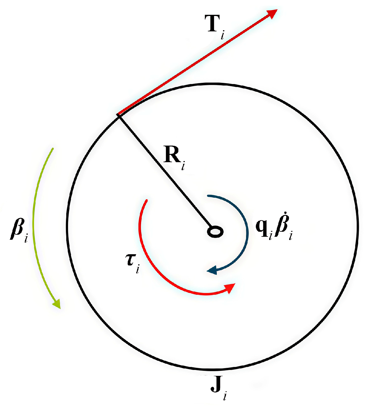
Let us consider the dynamics of the CDPR drive, which consists of a servomotor shaft with lumped parameters and a winch drum for winding a cable. The dynamic model for the servomotor shaft and the cable-winding drum is shown in
Figure 6.
In
Figure 6,
is the angle of rotation of the
i-th drive motor,
is the radius of the
i-th winch drums,
is the moment of inertia of the
i-th servomotor and the winch drum,
is the torque of the
i-th servomotor and
is the dissipation coefficient of the i-th drive (i = 1, …, 4).
The dynamic equation for the servomotor shaft and the cable winch drum is
where
,
,
,
,
,
Assuming that the torque of the CDPR drive servomotors keeps the cables in tension, from Equation (13), we can determine the tension of the cables as a function of the torques of the drive motors:
The general model of the dynamics of the CDPR system is obtained by combining the equations of motion of the platform and the drive. To obtain an equation relating the i-th angles of rotation of the drive motor with the position of the end effector , we assume that all are equal to zero when the geometric center of the platform is located at the origin of the frame base .
The change in the length of the
i-th cable is equal to
, where
is the length of the cable obtained from the solution of the inverse kinematics problem, and
is the initial length of the
i-th cable.
For convenience, let us rename the position vector of the final effector to , i.e., .
The successive time derivatives of Equation (16) take the form
Substituting Equations (17) and (18) into Equation (14) gives
Substituting Equation (19) into Equation (12), we obtain
Let us write Equation (20) of motion of the CDPR in the standard Cartesian form [
26],
where
is the equivalent inertia matrix and
are nonlinear terms:
where
is the identity matrix.
Equations (14)–(23) can be used to solve the servomotor torque that generates the cable tension that is necessary for the platform motion.
2.5. Linear Drive of Vertical Moving Platform
For the earthquake simulator to reproduce the given earthquake seismogram along the Z axis, it is necessary to ensure the translational motion of the vertical moving platform. To ensure the motion of the vertical moving platform, four linear drives with ball screw transmission are installed at the top of the rectangular platform.
Figure 7 shows a ball screw linear actuator that is designed to lift a vertical moving platform. The drive consists of a stepper motor connected through a coupling with a lead screw with a nut mounted on a linear guide; a slide is fixed on the nut, which is connected to a vertical moving platform.
The dependence of the slide stroke
on the rotation angle of the screw
is determined by the formula
where
is the pitch of the screw.
The linear velocity of the slider
is determined by the formula
where
.
The gear ratio of the ball screw spline is
. The torque
of the stepper motor is determined by the formula
The value of the slide acceleration is taken from the earthquake seismogram acceleration graph, and is ¼ of the mass of the vertical moving platform with a load.
2.6. Control System of a CDPR
The control system of a CDPR can be developed on the basis of the equation of motion of the CDPR in the standard Cartesian form in Equation (23). The input parameters of the CDPR are the torque vector of the actuator . Each component of the vector must be positive or at least equal to zero (usually a small positive value).
Let us introduce a virtual generalized input Cartesian force
[
26],
Since the structure matrix has a dimension of 2 × 4, this virtual generalized input Cartesian force has a translational Cartesian space dimension of 2. The components of are not limited to positive values.
If we develop a control for the input virtual Cartesian force
, we can always find the real control input torque
with all positive components that satisfies Equation (27) if the position of the CDPR is within the static workspace. Consider a dynamics equation,
We use a Cartesian PD controller to monitor the positioning error
where
is the given Cartesian position. The calculated torque control law for the input virtual Cartesian force
can be expressed as
where
are 2 × 2 diagonal matrix gains. The inertial terms
consist of a common Cartesian matrix of inertia depending on the position of
and the Cartesian acceleration components
; the nonlinear terms are
.
In Equation (30), the influence of the terms of the nonlinear dynamics
is excluded and the inertial terms are taken into account using the calculated torque method [
27]. Equation (30) uses the desired Cartesian values of
. Using the actual
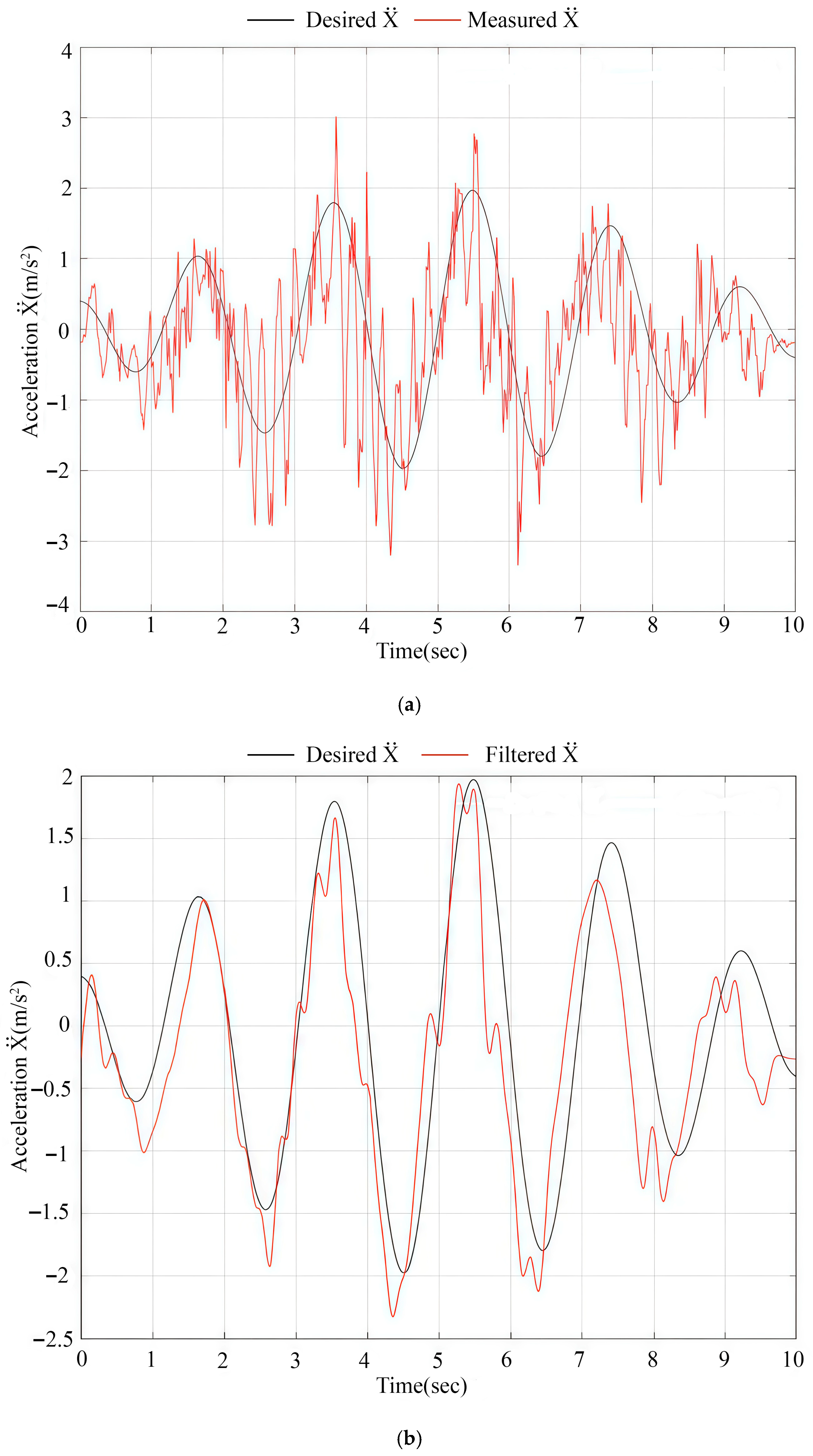
values from the feedback from the actuator encoder sensors and the forward kinematics solution causes problems with sensor noise and second derivative
errors. To eliminate sensor noise and digital differentiation errors, we used the method proposed in the paper [
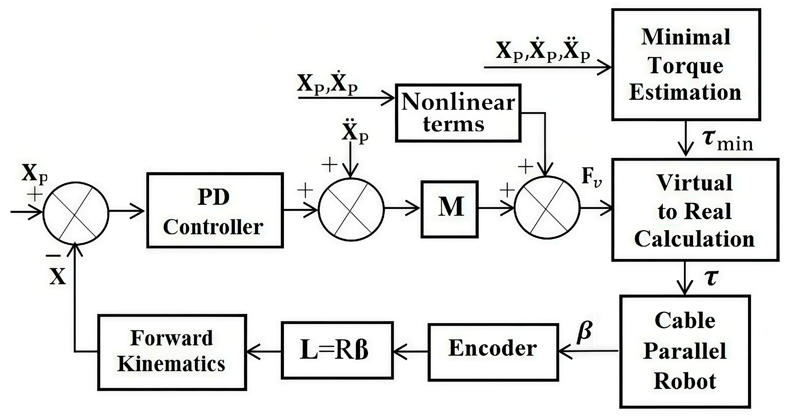
28]. The control scheme of the CDPR is shown in
Figure 8 [
26], and consists of a PD controller, a block for determining the virtual generalized input Cartesian force
and a block for calculating the real torque of the drive (virtual-to-real calculation) with dynamic estimation of the minimum torque (minimum torque estimation
) to ensure the constant maintenance of the cable tension, despite the dynamics of the CDPR. We adopted the scheme of the CDPR from [
26] due to its practical convenience and reliability. Other studies on CDPR control are also available; for example, the paper [
29] discusses a hybrid algorithm for CDPR cable tension and length compensation, which effectively compensates for errors while simultaneously controlling the tension distribution and cable length, improving the dynamic performance and ensuring stable control. The paper [
30] introduces novel methodologies in sliding mode control for CDPR, including innovative nonlinear sliding surface formulations.
The position of the
X is determined using the feedback of the encoder, which gives the rotation angles of the
i-th drive motor
to determine the lengths of the cables
. Further, by solving the direct kinematics of the CDPR (6), we determine the Cartesian position
. This feedback scheme works well only if sufficient tension is constantly maintained in all cables [
26].
For control, we need to calculate the real torques of the actuator τ, taking into account the virtual forces . The solution of the under-determined is similar to the solution of the optimization task in Equation (10).
For normal operation of the CDPR, the cable tension vectors
must always be positive during their operation.
The calculation of the minimum torque for each drive to maintain the tension of the cables is determined from Equation (31).
Equation (32) makes it possible to dynamically estimate the minimum tension of each CDPR cable and prevents sagging during its motion when the condition is met.
4. Conclusions
This paper presents an earthquake simulator prototype for reproducing three-dimensional, long-period ground motion during an earthquake, simulating real earthquake seismograms. The mobile platform of the earthquake simulator prototype performs planar motion in the direction of the X and Y axes due to the tension of the CDPR cables, and the vertical translational motion of the platform along the Z axis is performed by linear screw drives.
A control interface of the prototype earthquake simulator is designed to reproduce a given earthquake seismogram. In addition, there is the possibility of manual control of the translational motion of the prototype earthquake simulator, both forward–backward and left–right.
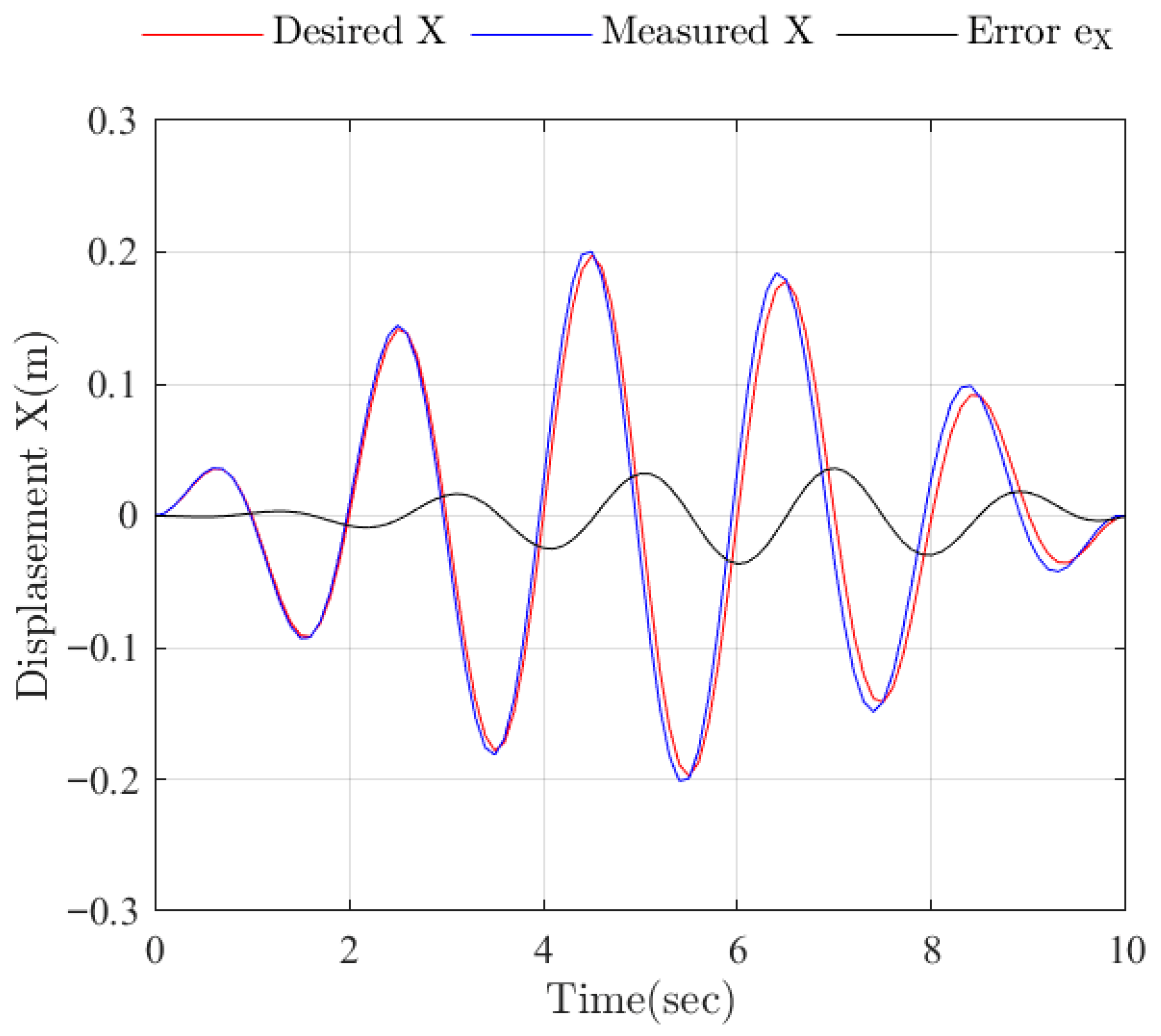
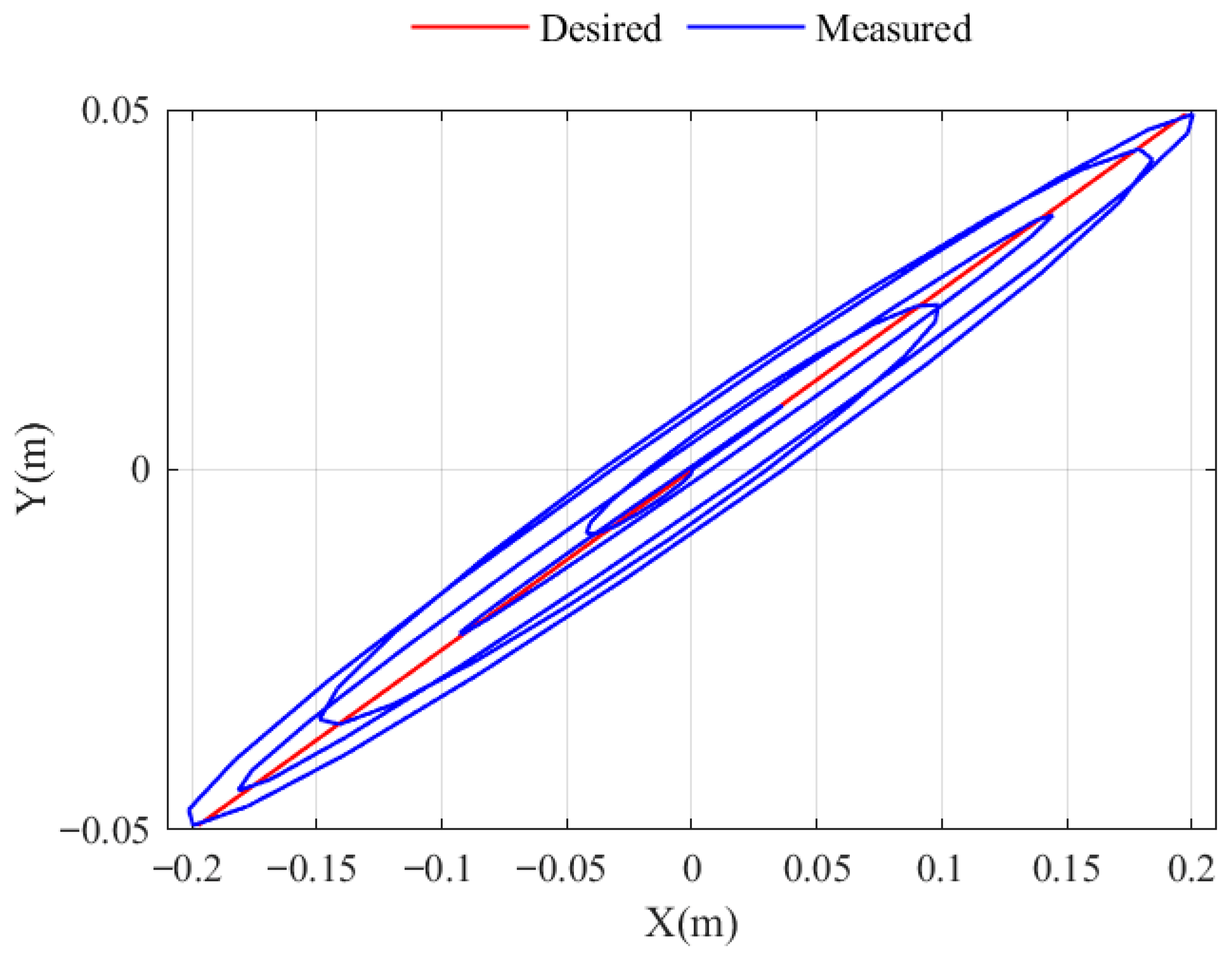
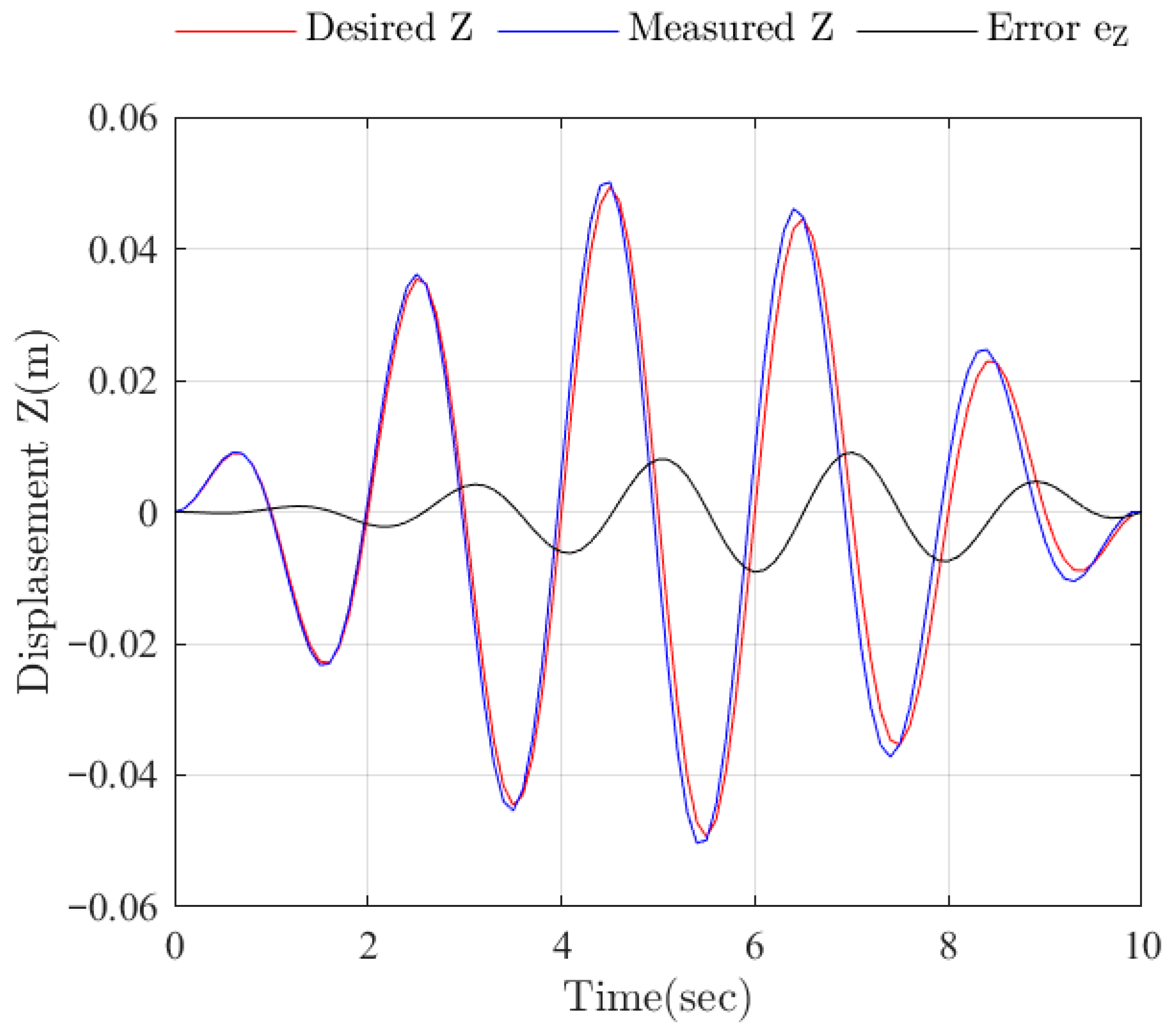
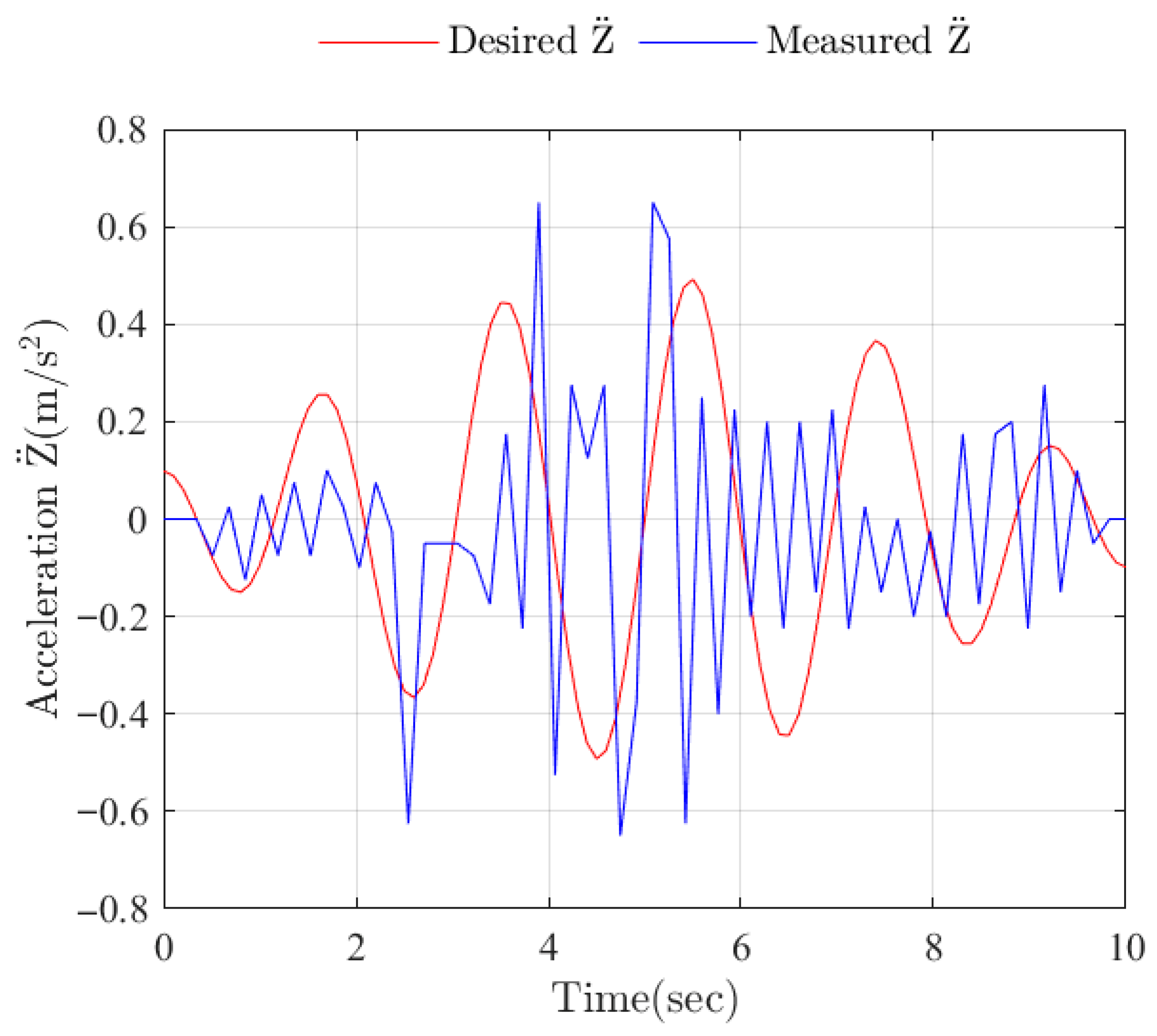
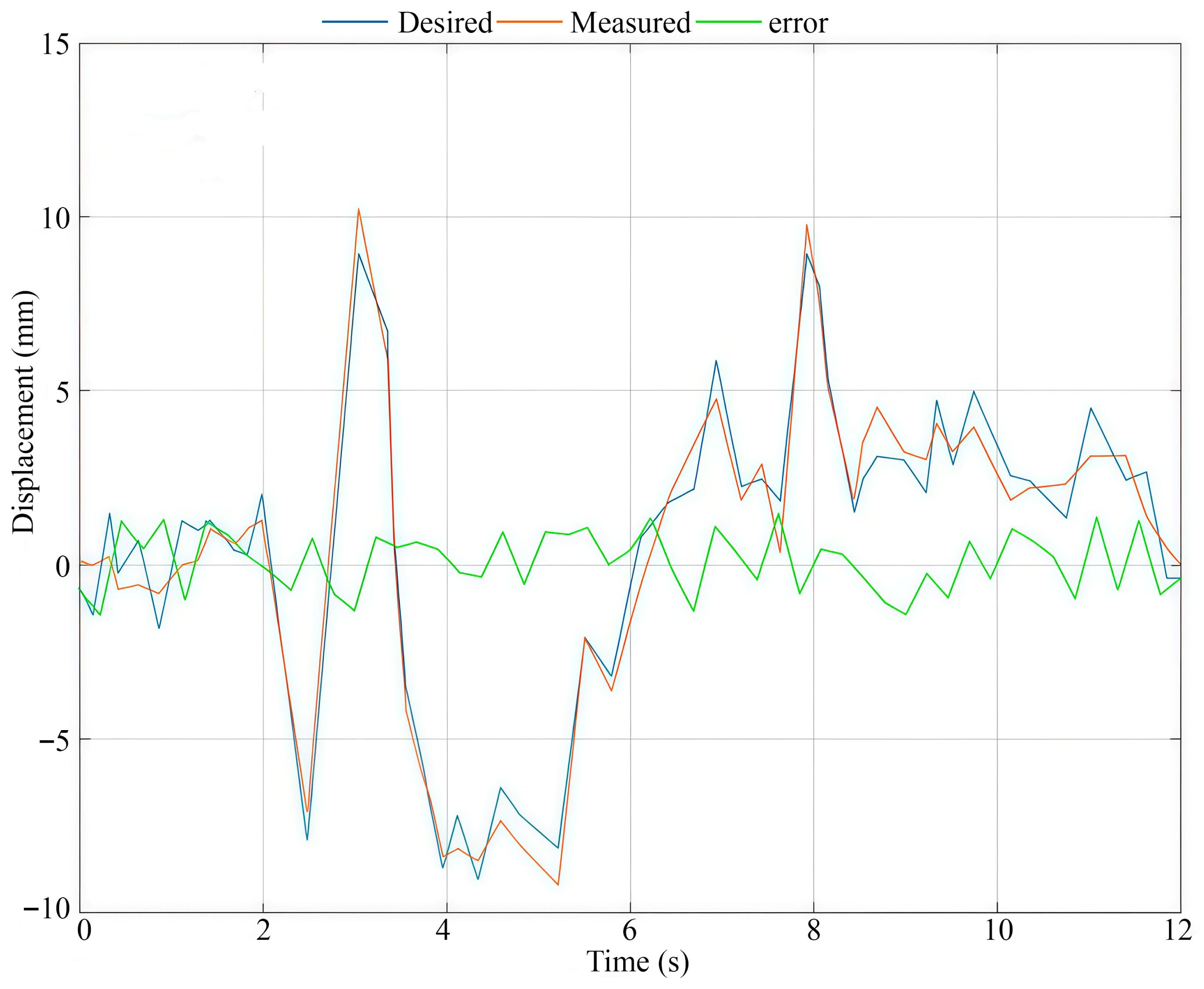
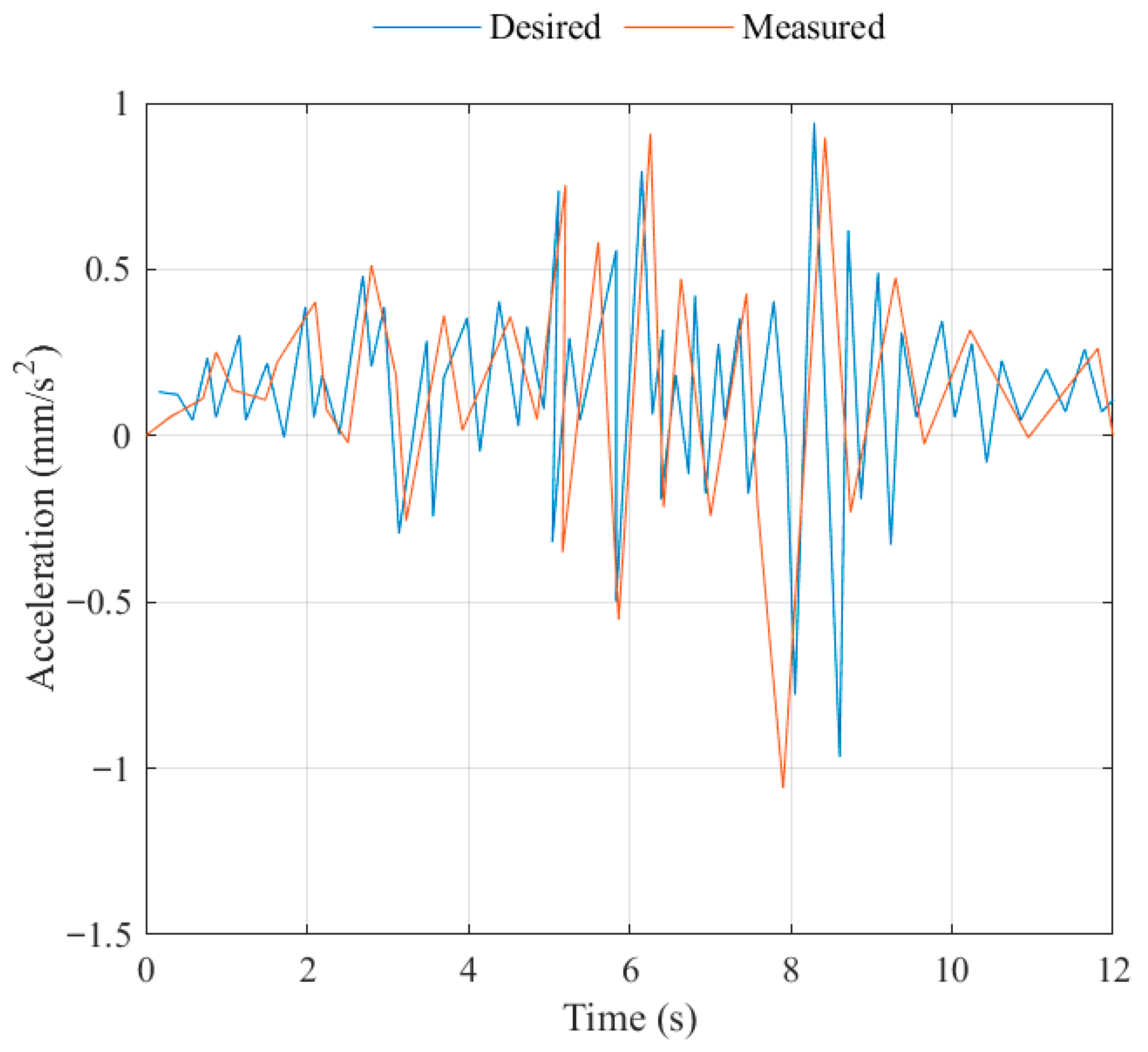
Experimental tests of the earthquake simulator prototype were successfully conducted with the trajectories of the mobile platform motion in the directions of the X and Y axes and the motion of the vertical platform in the form of a sinusoidal wave with a frequency of 0.5 Hz, the amplitude of which was modulated by an envelope with a frequency of 0.05 Hz. The following maximum amplitudes were desired along the X axis: within ±0.2 m, along the Y axis within ±0.05 m and along the Z axis within ±0.05 m. The results of the experimental tests have shown the ability of the prototype earthquake simulator to successfully reproduce a seismogram of a three-dimensional, long-period ground motion during an earthquake.
Future work will focus on increasing the accuracy of reproducing a real seismogram of a three-dimensional, long-period ground motion during an earthquake, in order to improve the mechanism for moving the platform in the vertical direction in order to increase the accuracy of the earthquake simulator. The simulator will be applied in conducting experimental research on the stability of building models and their foundations during a three-dimensional, long-period earthquake, together with an investigation on human reactions to earthquake motion. We plan to use an earthquake simulator prototype to train people on how to behave during an earthquake using virtual reality technology.
