Abstract
This paper presents the design and testing of a lightweight, low-cost robotic arm with an extended vertical range. The 9-degree-of-freedom (DOF) system comprises a 6-DOF arm and a 3-DOF gripper. To minimize weight, the six wrist and gripper joints are cable-driven, with all actuators relocated to the shoulder assembly. As a result, the wrist and gripper only weigh 222 g and 113 g, respectively, significantly reducing the inertia on the end effector. The arm utilizes a SCARA-configuration that slides along a tower for extended vertical reach. A key innovation is a closed-section frame that attaches the arm to the tower, in which the bending and torsional loads from the payload can be directly transferred onto the static structure. In contrast to conventional design, this design does not require the shoulder motor to take the bending load directly. Instead, the motor only needs to overcome the rolling friction of the reaction load. Experimental results demonstrate that this approach reduces the required motor torque by a factor of 30. Consequently, the prototype can manipulate a 3 kg payload at a 0.5 m lateral reach while weighing only 4.5 kg, costing USD 1200, and consuming a maximum of 11.1 W of power.
1. Introduction
1.1. Background
Currently, several common types of robotic arms are used in industry. Among them, two categories are particularly prevalent in modern industrial and collaborative applications: articulated robot arms and SCARA robots. A representative example of the articulated type is the UR3 developed by Universal Robots [1]. This arm has a total of 6 DOF (degrees of freedom) with three motors on the wrist to provide the necessary dexterity to orient the end-effector/gripper. The wrist (including motors) weighs approximately 2.5 kg. Since the end-effector/gripper is typically the main contact point between humans and robots, this mass may pose safety risks in the event of a malfunction. Another limitation of this design is its limited vertical range, particularly when the arm is fully stretched. This is a critical design limitation in some industries that are moving towards mobile robots, as these robots need to pick objects from the floor and still be able to place them on a high shelf.
Another widely used family is the Selective Compliance Assembly Robot Arms (SCARA) robots. SCARA is well known for its precision, efficiency, and high-speed planar motion, as only one joint typically operates against gravity [2]. This category has experienced exponential adoption in industrial applications due to its high-speed performance and compact design, and they have become a central player in various industries [3]. They have been widely employed in high-speed industrial applications such as electronics assembly, pick-and-place, and packaging [4]. Their compliance in the horizontal plane and rigidity along the vertical axis make them well-suited for precise planar tasks. However, SCARA robots present several drawbacks. First, their vertical range is often constrained, limiting tasks such as floor-level pickup or storage at elevated heights [5]. Second, most designs provide only a single DOF at the wrist, reducing dexterity for complex manipulation [6]. Finally, the use of heavy steel screw shafts and direct-drive actuators results in high inertia, low payload-to-weight ratios, and significant safety risks in collaborative environments [7].
Furthermore, more types of robot arms are used in industry, classified into geometric categories, such as spherical, cylindrical, Cartesian, and so on [8]. For example, anthropomorphic industrial robot arm ABB IRB 140 with a spherical wrist represents a major class of industrial manipulators. This work focuses on comparing articulated and SCARA configurations, which are most relevant to the design proposed here.
1.2. Related Work
To overcome the large inertia and safety concerns of conventional manipulators, cable-driven transmission systems have been increasingly explored. By relocating actuators to the base or shoulder and transmitting torque via lightweight cables, these designs minimize distal inertia and enable safer operation. The AMBIDEX arm, developed by Naver Labs, consolidated motors near the shoulder to achieve an overall arm mass lighter than that of a human arm while maintaining dexterity [9]. Similarly, Tanaka and Hamaya introduced the “Twist Snake”, a manipulator with all actuators at the base, demonstrating the feasibility of high-reach cable actuation [10]. In addition to rigid arms, cable-driven soft robotic arms show advantages in terms of large workspace and low-inertia operation [11]. Lightweight robotic arms combining rigid and soft elements also demonstrate the advantages of low energy consumption and high deployability [12].
Recent works have also advanced structural optimization and reliability. Nguyen and Chow proposed a low-cost, cable-driven robotic arm with low-inertia motion and improved long-term cable durability through a novel tightening mechanism [13]. However, the antagonistic cable pair driving the yaw joint may be intertwined and rub against each other, causing durability issues. Jiang analyzed motion-decoupling mechanisms for multi-joint cable-driven robots, introducing pulley-guided routing to maintain tension during articulation [14]. In parallel, lightweight hybrid structures combining carbon-fiber-reinforced polymer (CFRP) and aluminum alloys have been proposed to reduce mass while preserving stiffness [15]. Further research has shown that CFRP composite materials can effectively increase the natural frequency of robotic arms and reduce their end deflection [16]. Cable-driven micromanipulators have further highlighted the adaptability of cable transmissions across application domains, including surgical robotics [17]. In minimally invasive surgery, tension-sensing and friction-compensation mechanisms for cable-driven systems have been proposed to enhance operational precision and safety [18].
1.3. Contributions
This paper introduces a novel 9 DOF cable-driven SCARA robotic arm. The main contributions are as follows:
- Cable-driven vertical lifting module: A cable-lifted closed-section frame with a self-reversing spool to maintain orderly winding during long-stroke vertical motion. The loop frame design allows efficient transfer of the bending and torsional loads from the robot arm onto the static tower. As a result, the maximum torque requirement of the motor is significantly reduced.
- Compact 3 DOF wrist design: A decoupled design with three rotational DOF, with no intertwined cables, resulting in higher durability. A lightweight design with only 222 g allows safer human interaction. A compact design with a smaller moment arm results in lower torque requirements for the wrist motors.
- Cable-driven 3 DOF gripper: The new wrist design allows a hollow tube for additional cables to go through. As a result, the design incorporates a 3 DOF gripper actuated through cables driven by motors near the shoulder. By moving the motors from the gripper to the shoulder, the design can increase the quantity and size of the gripper motors, potentially enabling more versatile and higher-force grasps.
- Decoupling and tightening mechanisms: Pulley-based decoupling at the elbow and wrist. A dual-layer pulley design to help maintain cable tension with reduced height for a compact design.
An analytical comparison with a shoulder-driven articulated baseline indicates up to 30-fold reduction in shoulder torque. The prototype successfully manipulates a 3 kg payload at 0.5 m reach, while weighing only 4.5 kg, consuming up to 11.1 W of power, and costing approximately USD 1200. Additional technical details, including range of motion, repeatability, and payload capacity, are presented in the experimental section (Section 3).
2. Materials and Methods
2.1. Cable-Driven SCARA Robotics Arm Configuration
The proposed manipulator in Figure 1 adopts a PRRR (prismatic–revolute–revolute–revolute) backbone, in which the last revolute joint corresponds to the conventional SCARA wrist rotation. Unlike conventional SCARA robots with only 1 DOF on the wrist and 1 DOF for the gripper, the new design has a total of 3 DOF on the wrist and another 3 DOF on the gripper. These additional DOF are design-level provisions intended to expand the distal orientation workspace and approach versatility. Such kinematic redundancy can be valuable in collaborative and service applications where part orientation and accessibility vary [2,19].
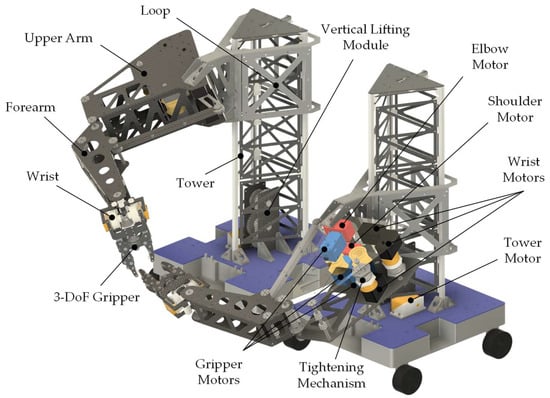
Figure 1.
Cable-driven SCARA with 8 motors near the shoulder joint and 1 motor at the root of the tower.
Our design has 9 motors in total, with 8 motors near the shoulder joint and 1 motor at the base of the tower. It is based on the ROBS-802 motor by OCServo (Guangzhou, China) with specifications listed in Table 1. Unlike conventional robot arms, in which heavy actuators are distributed at the wrist and elbow, the actuators in the proposed design are concentrated near the proximal shoulder joint. This reduces the moment arm and lowers the motor torque requirements. The shoulder joint is directly actuated by a motor mounted on the vertical loop, while motion at the elbow is transmitted through a parallelogram four-bar linkage that preserves geometric consistency between input and output links. The distal wrist degrees of freedom are driven via cable routing from proximal motors, supported by decoupling mechanisms to maintain constant tension. This configuration is intended to reduce the inertia of the moving links, which can help lower impact forces in the event of collision and improve safety for collaborative applications. In contrast, conventional SCARA robots with distal actuators tend to have higher moving inertia and may raise safety concerns in collaborative settings.

Table 1.
Motor specifications for ROBS 802 by OCServo.
To allow the robot arm to move at a higher speed without excessive vibrations, both the upper arm and forearm design has more stiffeners as compared to our previous design [13]. The design incorporates a closed-section design with an internal torsional box and side plates, as shown in Figure 2, added for higher torsional and bending stiffness.
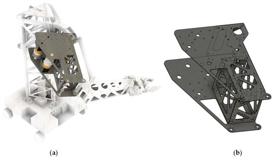
Figure 2.
Composite frame of the upper arm with multiple side plates to provide torsional and bending stiffness: (a) location of the composite frame within the robot arm; (b) perspective view of the composite frame of the upper arm.
In conventional SCARA robots, vertical motion is typically actuated by multiple linear actuators. These actuators use steel screw threaded shafts to enhance wear resistance; however, the shafts are relatively heavy and, when subjected to high bending and torsional loads from the robot arm, become susceptible to severe wear or jamming due to dirt and misalignment. To resolve these design issues, the vertical motion of the current design is achieved by a cable-lifted closed-section frame that slides along a triangular tower, as shown in Figure 1. This static tower is made of three lightweight aluminum tubes that are connected and stiffened with composite frames for higher torsional and bending stiffness.
The robot arm is mounted on a closed-section frame that loops around the tower. The lifting carriage runs along the tower rails via roller on linear guide supports, with preload adjustment applied to maintain tight contact and reduce vibrations. Compared to screw-driven linear stages, this scheme reduces system mass and allows back-drivability, while still providing sufficient rigidity for vertical translation. The upward motion is actively driven by the motor, while the downward motion is passively assisted by the combined weight of the platform and arm. To further improve accessibility in practical scenarios, the arm in Figure 3a is mounted at a 25° inclination relative to the horizontal plane. This geometry enables the end effector to approach tables and shelves at more ergonomic angles while reducing interference with any objects obstructing the workspace.
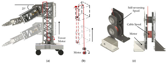
Figure 3.
Vertical lifting module. (a) Vertical lifting module with the robot arm inclined at 25°; (b) schematic diagram of the vertical lifting module principle; (c) vertical lifting design with a self-reversing spool to ensure neat winding.
To ensure higher accuracy during the long travel of the prismatic joint, the spool is coupled with a self-reversing guide mechanism shown in Figure 3c, which ensures neat winding and prevents entanglement during multiple cable layers.
2.2. Torque Relief Using Loop Module Design
Adapting from the previous design [20], we have built an articulated robot arm as shown in Figure 4, with a 0.5 m reach. This prototype is used as a reference for comparison, since it employs the same motor specifications and reach as the proposed design. By keeping these conditions identical, the effect of the structural configuration on payload capacity and torque demand can be directly evaluated. In this design, the vertical motion of the payload is actuated by the shoulder motor. The shoulder motor directly resists the payload torque at full reach, leading to high torque demands and limited payload capacity. Due to the high torque requirement, the shoulder joint requires two synchronized motors.
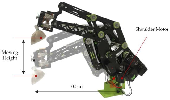
Figure 4.
Articulated robot arm with 0.5 m reach [20].
In contrast, the proposed cable-driven vertical lifting scheme converts this large shoulder torque into two opposing reactive forces onto the static tower, as shown in Figure 5. For vertical motion, the motor just needs to overcome the rolling friction from the moment reaction loads and the robot arm’s weight. Given that the rolling friction coefficient is relatively low in a range of 0.001 to 0.02, the cable force needed to lift the loop module is relatively small. Hence, a much lower torque requirement is needed for the spool-driven motor. To explain this advantage, we derive a simplified payload model of the spool-driven mechanism and compare it against the direct shoulder drive baseline under the same motor specifications.
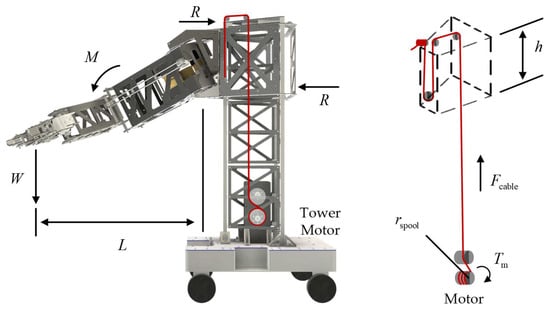
Figure 5.
Free body diagram of the tower-based cable-driven design.
The goal of this section is to establish a theoretical framework linking the rated motor torque to the payload achievable by the cable-driven vertical lifting scheme. The analysis also contrasts this result with the direct shoulder actuation baseline, thereby illustrating the torque-relief effect of the proposed configuration.
With a payload, , on the end effector, the robot arm’s shoulder is subjected to a moment load of
where is the horizontal reach of the payload. In prior tests, a full-extension shoulder posture at has been adopted as the load-bearing benchmark.
This moment is converted into two opposing reactive forces, , onto the static tower:
where denotes the effective loop module height.
The cable must overcome both gravity and column friction. However, due to the relatively small rolling friction, , the cable force is primarily the arm’s weight:
As a result, the motor torque requirement would be
where is the spool radius.
In Table 2, the calculation based on a simplified model shows that the rolling friction component of the cable force is approximately 12% of the overall force. As a result, the moment resulting from the payload is primarily taken by the static tower rather than the cable motor. Therefore, there is a 30-to-1 advantage of the vertical lifting module design over the articulated robot arm in the motor torque requirement.

Table 2.
Comparison of the maximum torque requirement between the cable-driven vertical lifting module and the articulated robot arm.
2.3. Elbow Joint Design and Decoupling Mechanism
A critical challenge in cable-driven robotic arms is that cables inevitably cross multiple joints. When the proximal joint rotates, the cable routing length changes, leading to loss of cable tension and inaccurate torque transmission at the distal joint. To address this, a decoupling mechanism based on Jiang is integrated at the elbow joint to maintain constant cable tension throughout articulation [14]. Figure 6 shows two side pulleys that are added adjacent to the elbow joint pulley to achieve a wider range of elbow motion.
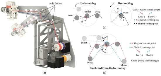
Figure 6.
Schematic of the elbow joint over–under decoupling mechanism: (a) Schematic of the cable transmission for the wrist. A single continuous cable (red and blue segments) is routed from the wrist pulley and wound back to the motor spool. (b) When the forearm rotates downward, there is a change in the contact length between the cable and the elbow joint pulley. Left: under routing, where the cable is routed under the pulley (red), the contact arc decreases by , resulting in cable loosening. Right: over routing (blue), where the contact arc increases by , resulting in cable tightening. The original and shifted contact points are marked, and the change in effective cable contact length is proportional to the change in contact angle (); (c) Combined over–under routing scheme, where the opposing changes in contact length compensate each other, resulting in a stable cable length and effective decoupling during joint rotation.
As illustrated in Figure 6, when the forearm rotates downward by an angle , the cable routed over the pulley experiences an increase in contact arc, while the cable routed under the pulley experiences a corresponding decrease. The change in cable length can be expressed as
where is the pulley radius and is the change in contact angle. The positive sign corresponds to the under-routing path, where a reduction in contact arc results in an increase in cable length, while the negative sign corresponds to the over-routing path, where an increase in contact arc results in a decrease in cable length. By combining both routing paths, the incremental length variations cancel each other:
Ideally, keeping the total wrapped length constant and helping stabilize tension. This over–under routing principle forms the fundamental basis for the passive decoupling. In experiments, continuous elbow-joint motion showed no visible slack.
2.4. Wrist Mechanism and Cable Actuation
Wrist designs for robotic arms face a significant challenge in achieving 3 DOF—pitch, yaw, and roll—within a compact and lightweight structure. While several innovative mechanisms have been developed, they each have limitations. The spherical scissor mechanism [21,22] offers 3 DOF motions through interconnected linkages, but existing designs can only actuate two DOF using cables. This is because one DOF is located at the endpoint, which complicates cable routing as the mechanism moves along its spherical surface. The spherical parallel mechanism [23] provides high stiffness and precision, but its range of motion is limited by the length of its links, constraining the design of a compact system necessary in many robotic applications. While the active ball joint mechanism [24] can achieve 3 DOF without slippage and offers high dynamic control, integrating cable-driven mechanisms into its design is complex and challenging.
A promising approach, as demonstrated in our previous work [13], is the differential mechanism, which offers a compact design for 3 DOF motion. It controls roll and pitch through the angular difference between two motors, with a separate motor for yaw rotation, allowing for independent control of all 3 DOF. However, existing cable-driven differential mechanisms [25] do not allow cables to pass through the joint to the distal segments, limiting overall robot design flexibility.
These limitations—the difficulty in achieving all 3 DOF with cable-driven mechanisms, the lack of compactness, and the inability to route cables through the joint—hinder the widespread adoption of existing designs. Our novel 3 DOF wrist mechanism addresses these challenges by adopting a new cable-driven approach with three motors. The design employs a lightweight structure where only six cables are required for roll, pitch, and yaw rotation.
The proposed cable-driven differential mechanism is composed of two wheels, a set of three bevel gears, a hollow tube, three sets of cable guides, and four sets of pulleys. Figure 7a shows the three sets of cable guides connected to three motors.
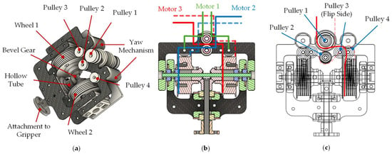
Figure 7.
Cable-driven mechanisms for the compact wrist: (a) Cable-driven differential mechanism for the compact wrist; (b) cable attachment method for a three-motor configuration in cross-sectional view; dashed lines indicate the cable routing at the lower side; (c) decoupling mechanism for wrist yaw motion, illustrating the cable routing required to actuate Wheel 2 with Motor 3 while maintaining constant tension during yaw rotation; dashed lines represent the cable path at the lower side.
The actuation method is illustrated in Figure 7b. The rotation of Motor 1 would actuate the yaw motion through the yaw tightening mechanism. Pitch motion is achieved by pulling both cables from Motors 2 and 3 such that both wheels rotate in the same direction. Conversely, when they move in opposite directions, the two wheels would also turn in opposite directions, resulting in the rolling motion. This integration achieves compactness, ease of assembly, and stable tension maintenance over the full range of motion. As the pitch and yaw motion might be straightforward to be actuated, the roll motion () is driven by the three bevel gears (2 side gears and 1 carrier gear). The relationship between the rotations of the side gears (, ) and the resulting roll motion is expressed as
where and are the rotations of two side bevel gears, attached to the Wheel 1 and 2, while and are the number of teeth of side gears and carrier gear, respectively.
However, yaw rotation in the wrist mechanism introduces a challenge: tightening and loosening of cables attached to Motors 2 and 3 as they navigate Pulleys 1, 3, and 4. As the joint articulates, the cable length changes, leading to a loss of consistent tension. To counteract this, a decoupling mechanism is integrated in Figure 7c. This mechanism ensures that the total cable length remains constant, preserving stable tension.
Figure 8 provides a detailed view, using Wheel 2 as an example. This mechanism requires the two cables from Motor 3 to route over opposing sides of Pulley 1. When the yaw motion causes the cable on one side to shorten (tighten), the cable on the opposite side lengthens (loosens). This routing ensures the length variations cancel each other out, maintaining constant cable tension. To achieve this necessary opposing route, Pulley 2 is introduced to redirect the cable to the opposite side of the wheel. The cable route for Wheel 1, using Motor 2, is like this method. As shown in Figure 9, another feature is the cable passage. Unlike existing differential mechanisms, our design incorporates a hollow tube mounted within a bevel gear, enabling three cables to pass directly through the joint and connect to the distal segments. By increasing the size of the bevel gears, this passage can accommodate even more cables, which is particularly advantageous for multi-segment robot arm designs. This internal routing feature eliminates the need for external routing with additional components like Bowden cables.
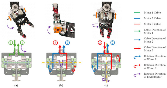
Figure 8.
Actuation of 3 DOF motion using the cable differential system: (a) Yaw rotation; (b) Pitch rotation with wheels rotating in the same direction; blue and red lines indicate cable routing at the upper side; (c) Roll rotation with wheels rotating in opposite directions; the red dashed line represents the cable path at the lower side. The resulting motion is indicated by solid red arrows.
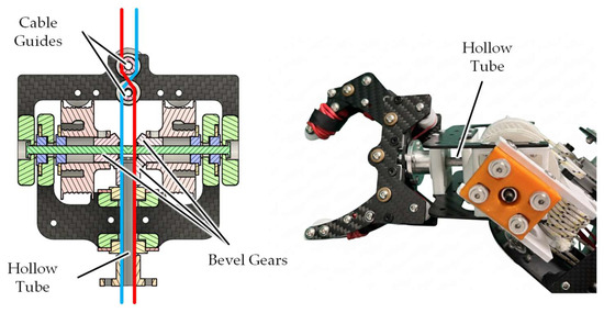
Figure 9.
Cross-sectional view for cable passage through the wrist mechanism. The illustration shows how two cables pass through a hollow tube attached to a bevel gear, a key feature that allows for a compact design and internal routing to distal joints.
2.5. 3-DOF Cable-Driven Gripper
Most finger grippers only have a single DOF. Such systems maintain stable gripping through friction, as shown in Figure 10a. Unfortunately, the friction force often varies considerably, and that would result in unsuccessful gripping. Many plastic-wrapped or plastic-made objects exhibit low friction, particularly when the surface is slightly moist. Other objects made of soft materials, such as meat or fragile material, limit the amount of gripping force to generate the necessary friction to overcome the gravitational force. In addition, during the movement of the gripper, the inertia acceleration may alter the reaction load on the finger. This could result in a temporary loss of friction force and result in unsuccessful gripping. To illustrate the natural biomechanics of human grasping, Figure 10b shows a human finger joint rotation, highlighting the multi-DOF motion that inspires the design of more dexterous robotic grippers.
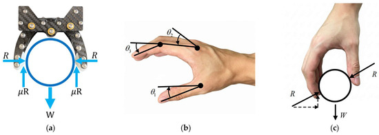
Figure 10.
Finger gripper concepts: (a) Free-body diagram (FBD) of a 1-DOF finger gripper, where the gravitational force of the object is resisted by frictional forces at the contact points; (b) Illustration of a human finger joint rotation; (c) Design of a cable-actuated 3-DOF finger gripper, which enables object grasping without relying on frictional forces.
To overcome this obstacle, a 3 DOF cable-driven gripper is proposed. It emulates the common DOF needed for human hands to grip different types of objects, as shown in Figure 10c. With 3 DOF, gripper can grab an object without heavily depending on the frictional force. In addition, the extra two DOF allow the gripper to be more versatile for handling objects of different widths. To make the gripper design compact, the joints are cable actuated. The motors are relocated away from the gripper and move towards the shoulder. As a result, the gripper, despite having additional DOF, only weighs 113 g.
To evaluate the 3 DOF finger against a 1 DOF baseline, we conducted a brief proof-of-concept comparison. Three cylindrical beverage cans with different diameters and fill levels were used; object dimensions and masses are listed in Table 3. Under comparable approach conditions, each object was attempted with a friction-reliant 1 DOF pinch and with the proposed 3 DOF cable-driven finger, as shown in Figure 11. Consolidated outcomes are reported in Table 4. The result shows the 3 DOF finger achieved successful grasps in more cases than the 1 DOF baseline.

Table 3.
Test objects for grasping comparison (cylindrical beverage cans): diameters and masses.
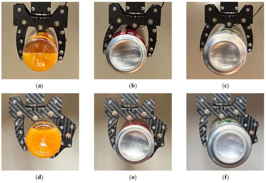
Figure 11.
Grasping examples from the proof-of-concept test: (a) 1 DOF gripper grasping Object 1; (b) 1 DOF gripper grasping Object 2; (c) 1 DOF gripper grasping Object 3; (d) 3 DOF gripper grasping Object 1; (e) 3 DOF gripper grasping Object 2; (f) 3 DOF gripper grasping Object 3 (objects as defined in Table 3).

Table 4.
Grasping outcomes for 1 DOF vs. 3 DOF fingers (“1” = graspable; “0” = non-graspable).
To realize the 3 DOF finger, three cables are routed from shoulder-mounted actuators through the wrist’s hollow tube to the gripper. The left finger provides one DOF, and the right finger provides two DOF (finger top and finger below motions). Multi-stage sleeves and pulleys are used to separate cable paths, control the bending radius, and reduce crossover, as shown in Figure 12. The cable ends are anchored to terminal screws at the distal joints.

Figure 12.
Cable routing and structure in a 3-DOF gripper: (a) 3 DOF gripper cable routing overview; (b) Left finger cable routing; (c) Right finger top cable routing; (d) Right finger below cable routing.
To demonstrate the capability of the proposed design, the gripper module was tested for a range of angular motions, as illustrated in Figure 13. This shows how the 3-DOF cable-driven gripper can execute coordinated joint rotations to adapt to different object geometries, further validating its versatility while maintaining a lightweight and compact structure.
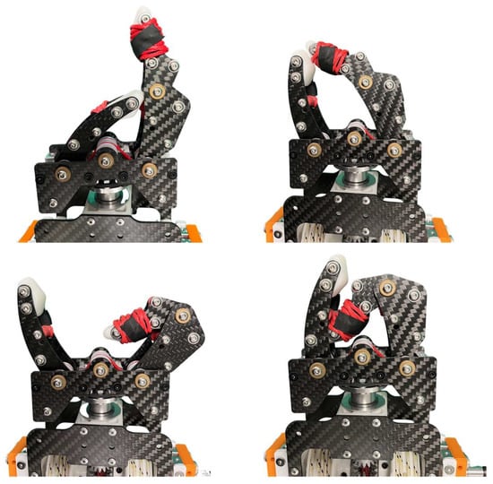
Figure 13.
Demonstration of the gripper module performing various angular motions.
2.6. Tightening Mechanism
To better accommodate the compact design of the SCARA arm layout, the height of the cable pulleys of the tightening mechanism is reduced. The inner and outer cable winding with five rounds on each segment was introduced to the cable pulley design, as shown in Figure 14, effectively reducing the height of the pulleys by 24% when compared to the previous design. A grooved pulley design was also incorporated to further reduce cable stress concentration and to guide/separate the cable paths, thereby reducing crossover risk at the yaw joint. This tightening mechanism is intended to facilitate re-tensioning and to mitigate long-term creep by distributing tension across multiple wraps.
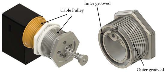
Figure 14.
Cable pulleys of a tightening mechanism with inner and outer grooves for cable winding.
3. Results
3.1. Range of Motion
The proposed manipulator adopts a PRRR backbone consisting of a base prismatic stage and two parallel yaw axes (shoulder and elbow), followed by a 3 DOF wrist and a placeholder 3 DOF gripper. This architecture extends the conventional SCARA design by combining vertical reach with enhanced dexterity at the end-effector. To ensure cable clearance and linkage safety margins, conservative range limits were first defined, as summarized in Table 5.

Table 5.
Range of motion of each joint. (All angles measured with respect to the base Z-axis; shoulder and elbow yaw axes are parallel.).
The range of motion of each joint was verified using the motor debugging interface. To avoid initialization jumps near 0° (where a small pre-offset could cause the encoder to roll over to the next revolution), the neutral reference was set at 180°. From this neutral point, each joint was driven until just before its mechanical stop, and the extreme angles were recorded. This procedure provided safe estimates of the effective ranges. The measured ranges confirm that the shoulder and elbow yaw joints, together with the prismatic tower and the three wrist DOF, can cover the intended workspace without encountering singularities or cable interference.
3.2. Repeatability Test
A repeatability test is performed to evaluate each joint when actuated individually, thereby assessing the overall motion repeatability of the robot. Table 6 shows the result with 10 repeated measurements on each joint. The shoulder motion experiences a relatively large error due to the large moment arm distance between the shoulder joint and the wrist. The wrist-roll motion also sees a significantly larger error. This is due to the differential tolerance of the three bevel gears. Nonetheless, the overall repeatability error (with three standard deviations) is less than ±0.1 mm, matching the specification of many commercial robot arms.

Table 6.
Repeatability result.
3.3. Load Test
A payload test was carried out to validate the load-handling capability of the proposed arm, as shown in Figure 15. A 3 kg mass was grasped by the gripper, with the arm fully extended to its maximum reach of 0.5 m. Under this configuration, the vertical tower motor bears the primary gravitational load, while the shoulder motor must compensate for the rotational inertia when driving yaw motion.
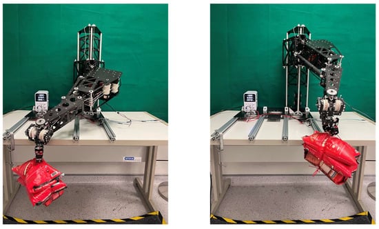
Figure 15.
Load testing of 3 kg.
The prototype successfully supported the 3 kg payload within the motor’s rated torque limit. There is no loss of stability or noticeable structural deformation. Under a 3 kg payload, both current and power profiles exhibit a characteristic surge during the joint motions. This surge occurs in both the shoulder and elbow joints, as the actuators must overcome the rotational inertia of the load while maintaining the commanded trajectory at higher angular velocities.
Figure 16 shows that the highest instantaneous power was recorded in the elbow’s motion, reaching 11.1 W, whereas other joints remained in the range of 5–8 W. This indicates that the motors only enter high-power output transiently when counteracting inertial effects. Since the maximum power utilized is well within the rated and stall power of the ROBS 802 motor at 17.6 W and 57.3 W, respectively, the durability of the motor would not be affected. It is assessed that the elbow sees a higher power requirement due to the additional frictional loss in the link design that drives the elbow rotation from the shoulder.
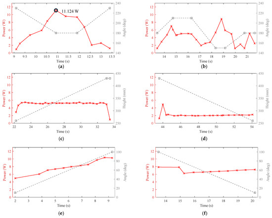
Figure 16.
Under a 3 kg payload, the elbow, shoulder, and tower modules were tested individually to record their power–angle/height profiles: (a) elbow horizontal motion; (b) shoulder horizontal motion; (c) tower upward motion; (d) tower downward motion; (e) wrist pitch upward motion; (f) wrist pitch downward motion.
During the tower’s downward motion, the actuation is assisted by gravity, resulting in a significant reduction in the power requirement compared with the upward motion. This demonstrates that the vertical module benefits from gravitational assistance in lowering operations, thereby reducing motor load and overall energy consumption.
Experiments have been conducted to compare the overall performance of the new vertical lifting module design with the conventional articulated design as discussed in Section 2.2. For the articulated arm, due to the large moment on the shoulder joint from the payload, the design requires having two motors on the shoulder joint for the pitching motion [20]. Keeping the power within the motor-rated torque limit, Table 7 shows that the articulated robot arm can only achieve a payload of 200 g. In contrast, the vertical lifting module design can achieve a payload of 3 kg. Considering the number of motors on the shoulder joint, the vertical lifting module design achieves a 30-to-1 payload advantage, consistent with the simplified model calculation shown in Table 2. The tests show the actual motor torque requirement is approximately 3-5 times higher than the simplified calculation due to the additional loads from the robot arm weight and the rotational acceleration during the arm movement.

Table 7.
The maximum payload for the cable-driven vertical lifting module and the articulated robot arm in the actual experiment shows 30 times improvement in payload per motor for the new design.
In fabricating the prototype, we prioritized cost-effectiveness and ease of deployment by using off-the-shelf components, simple manufacturing processes, and lightweight composite panels. Table 8 summarizes the breakdown of cost.

Table 8.
Cost breakdown of the prototype (USD).
Table 9 shows the comparison between the commercial UR3 robot arm by Universal Robots, an industrial-grade Epson T3-B401S SCARA, and the current cable-driven SCARA prototype. These systems achieve the same payload capacity of 3 kg and a reach of nearly 500 mm. However, our design incorporates 9 DOF compared to the UR3 of 6 DOF and Epson SCARA of 4 DOF, allowing additional DOF for an integrated gripper with more versatile contact. In addition, overall power consumption and weight are significantly less. The lightweight structure and cable-driven transmission led to low rotational inertia, which not only enhances responsiveness but also improves operational safety. These characteristics make the system highly suitable for collaborative environments with safe human–robot interaction. Furthermore, the prototype achieves comparable performance at a fraction of the cost, demonstrating its potential as a lightweight, low-cost alternative for industrial automation, educational robotics, and hobbyist learning.

Table 9.
Specification comparison between UR3, Epson T3-B401S, and the proposed cable-driven SCARA robot.
4. Discussion
This paper presents the development of a 9 DOF cable-driven robot arm capable of manipulating a 3 kg payload at 500 mm from the shoulder centerline. By mounting the robot arm on a vertical loop module, the moment from the payload can be directly transferred onto the static tower. As a result, the torque requirement on the shoulder joint is reduced by a factor of 30. In addition, the ability of the vertical module to slide along the tower allows the vertical range to be drastically enlarged. To reduce vibration, the design incorporates closed-section designs such as the torsional box on the arm, the loop module, and the tower. On the end effector, a novel compact 3 DOF wrist and 3 DOF gripper design actuated by cables is introduced. Weighing only 222 g and 113 g, respectively, makes them not just safer for human–machine interaction but also allows the robot arm to operate on a higher level without the need for heavy mass on the bottom to prevent toppling. In contrast to the conventional 1 DOF gripper, the compact 3 DOF gripper for more versatile gripping against friction loss.
Furthermore, two main directions for further improvement are outlined for future work.
- Kinematic modeling and control: The present work focused on the mechanical design and actuation characterization, while the task-space position control has not yet been fully implemented. The forward and inverse kinematics of the PRRR structure coupled with multi-stage cable transmission will be formulated in future studies to enable closed-loop trajectory control and dynamic motion compensation.
- Cable-driven durability enhancement and test: Future work would look at the durability performance of the system. Tests would be conducted to quantify the amount of cable loosening over time. Some improvements would be made to replace some 3D-printed plastic parts with metal components.
Overall, the results suggest that the proposed cable-driven architecture combining loop-module vertical actuation, low distal mass, and a compact 3 DOF wrist and 3 DOF gripper provides a feasible path to low-inertia, deployable robot arms. Completing the above control and durability studies will be essential for broader application and field deployment.
5. Patents
The robot arm depicted in Section 2 had patents awarded with registered number WO002025125430A1 and filed in Singapore with a registered number of 10202502056V on 25 July 2025 and in Germany with registered numbers of 102025123724.7 and 102025101513.9 on 18 June 2025 and 16 January 2025, respectively.
Author Contributions
Y.S. and Y.W.—concept, design, modeling, experiment and writing, W.T.C., T.M.K.—concept, design, writing, revision and proofreading. All authors have read and agreed to the published version of the manuscript.
Funding
The research covering the wrist design and tightening mechanism is partially supported by the Agency for Science, Technology and Research (A*STAR) under its IAF-ICP Program I2001E0067 and the Schaeffler Hub for Advanced Research at NTU.
Data Availability Statement
The data is contained within the article.
Conflicts of Interest
The authors declare no conflicts of interest.
References
- Universal Robots UR3 Robot Arm; Technical Specification; Universal Robots A/S: Odense, Denmark. 2021. Available online: https://howtorobot.com/sites/default/files/2021-12/universal-robot-ur3-technical-spec.pdf (accessed on 27 October 2025).
- Tay, S.H.; Choong, W.H.; Yoong, H.P. A Review of SCARA Robot Control System. In Proceedings of the 2022 IEEE International Conference on Artificial Intelligence in Engineering and Technology (IICAIET), Kota Kinabalu, Malaysia, 13–15 September 2022. [Google Scholar] [CrossRef]
- Sanjeewa, N.; Wathudura, V.M.; Kahatapitiya, N.S.; Silva, B.N.; Subasinghage, K.; Wijesinghe, R.E. Real-Time Coordinate Estimation for SCARA Robots in PCB Repair Using Vision and Laser Triangulation. Instruments 2025, 9, 7. [Google Scholar] [CrossRef]
- IRB 920T/IRB 920; SCARA Robot for High Precision Assembly. ABB IRB 920T/IRB 920 SCARA Robot; Technical Data Sheet; ABB Ltd.: Zurich, Switzerland, 2021. Available online: https://search.abb.com/library/Download.aspx?DocumentID=9AKK107992A6817&LanguageCode=en&DocumentPartId=&Action=Launch (accessed on 27 October 2025).
- Wang, Y.; Zhao, C.; Mei, D.; Tang, G.; Zhang, L.; Zhu, D. Structural Design and Position Tracking of the Reconfigurable SCARA Robot by the Pre-Filter AFE PID Controller. Appl. Sci. 2022, 12, 1626. [Google Scholar] [CrossRef]
- Suri, S.; Jain, A.; Verma, N.; Prasertpoj, N. SCARA Industrial Automation Robot. In Proceedings of the 2018 International Conference on Power Energy, Environment and Intelligent Control (PEEIC), Greater Noida, India, 13–14 April 2018. [Google Scholar] [CrossRef]
- Zhang, Z.; Guo, Q.; Grigorev, M.A.; Kholodilin, I. Construction Method of a Digital-Twin Simulation System for SCARA Robots Based on Modular Communication. Sensors 2024, 24, 7183. [Google Scholar] [CrossRef] [PubMed]
- Haider, A.F.A.; Haidar, F.A.; Nandha, K. A Review of Application Industrial Robotic Design. In Proceedings of the 2011 Ninth International Conference on ICT and Knowledge Engineering, Bangkok, Thailand, 12–13 January 2012; pp. 105–112. [Google Scholar] [CrossRef]
- Song, H.; Kim, Y.-S.; Yoon, J.; Yun, S.-H.; Seo, J.; Kim, Y.-J. Development of Low-Inertia High-Stiffness Manipulator LIMS2 for High-Speed Manipulation of Foldable Objects. In Proceedings of the 2018 IEEE/RSJ International Conference on Intelligent Robots and Systems (IROS), Madrid, Spain, 1–5 October 2018. [Google Scholar] [CrossRef]
- Tanaka, K.; Hamaya, M. Twist Snake: Plastic Table-Top Cable-Driven Robotic Arm with All Motors Located at the Base Link. In Proceedings of the 2023 IEEE International Conference on Robotics and Automation (ICRA), London, UK, 29 May–2 June 2023; pp. 1981–1988. [Google Scholar] [CrossRef]
- Wei, F.; Luo, K.; Zhang, Y.; Jiang, J. Structural Design and Kinematic Analysis of Cable-Driven Soft Robot. Actuators 2024, 13, 497. [Google Scholar] [CrossRef]
- Palmieri, P.; Melchiorre, M.; Mauro, S. Design of a Lightweight and Deployable Soft Robotic Arm. Robotics 2022, 11, 88. [Google Scholar] [CrossRef]
- Nguyen, V.P.; Chow, W.T.; Dhyan, S.B.; Zhang, B.; Han, B.S.; Wong, H.Y.A. Low-Cost Cable-Driven Robot Arm with Low-Inertia Movement and Long-Term Cable Durability. Robotics 2024, 13, 128. [Google Scholar] [CrossRef]
- Jiang, S.; Hua, D.; Wang, Y.; Ju, F.; Yin, L.; Chen, B. Design and Modeling of Motion-Decoupling Mechanism for Cable-Driven Joints. Adv. Mech. Eng. 2018, 10, 1–10. [Google Scholar] [CrossRef]
- Yin, H.; Liu, J.; Yang, F. Hybrid Structure Design of Lightweight Robotic Arms Based on Carbon Fiber Reinforced Plastic and Aluminum Alloy. IEEE Access 2019, 7, 64932–64945. [Google Scholar] [CrossRef]
- Khozeimeh, M.A.; Fotouhi, R.; Moazed, R. Static and Vibration Analyses of a Composite CFRP Robot Manipulator. J. Compos. Sci. 2022, 6, 196. [Google Scholar] [CrossRef]
- Wang, Z.; Yu, X.; Hai, M.; Qian, S.; Wang, D.; Li, Z. A Hybrid Method Combining Data-Driven and Model-Based Algorithms for External Force-Sensing and Haptics Control of Cable-Pulley-Driven Surgical Robotic Manipulator. J. Mech. Robot. 2024, 16, 101006. [Google Scholar] [CrossRef]
- Zhou, Z.; Yang, J.; Runciman, M.; Avery, J.; Sun, Z.; Mylonas, G. A Tension Sensor Array for Cable-Driven Surgical Robots. Sensors 2024, 24, 3156. [Google Scholar] [CrossRef] [PubMed]
- Nguyen, V.P.; Dhyan, S.B.; Chow, W.T. A Decoupling Module Based on a Geometrical-Balance Mechanism for Mitigating Cable Length Variation in Cable-Driven Applications. Machines 2024, 12, 755. [Google Scholar] [CrossRef]
- Castillo, A.; Chow, W.T. A028 Cable Actuated Robot Arm. Undergraduate Report; School of Mechanical and Aerospace Engineering, Nanyang Technological University: Singapore, May 2025. [Google Scholar]
- Kwok, T.M.; Cheng, H.H.; Yu, H. A 2-DOF Elbow Exoskeleton with Spherical Scissor Mechanism for ADL Assistance. In Proceedings of the 2023 IEEE International Conference on Robotics and Biomimetics (ROBIO), Koh Samui, Thailand, 4–9 December 2023; pp. 1–6. [Google Scholar] [CrossRef]
- Li, R.; Liu, Z.; Mi, W.; Bai, S.; Zhang, J. Design and Kinematic Analysis of a Novel Wire-Driven Spherical Scissors Mechanism. In Recent Advances in Mechanisms, Transmissions and Applications; Springer: Singapore, 2020; pp. 192–200. [Google Scholar] [CrossRef]
- Wu, G.; Caro, S.; Wang, J. Design and transmission analysis of an asymmetrical spherical parallel manipulator. Mech. Mach. Theory 2015, 94, 119–131. [Google Scholar] [CrossRef]
- Abe, K.; Tadakuma, K.; Tadakuma, R. ABENICS: Active Ball Joint Mechanism with Three-DOF Based on Spherical Gear Meshings. IEEE Trans. Robot. 2021, 37, 1806–1825. [Google Scholar] [CrossRef]
- Whitney, J.P.; Hodgins, J.K. A passively safe and gravity-counterbalanced anthropomorphic robot arm. In Proceedings of the 2014 IEEE International Conference on Robotics and Automation (ICRA), Hong Kong, China, 31 May–7 June 2014; IEEE: New York, NY, USA, 2014; pp. 6168–6173. [Google Scholar] [CrossRef]
- Epson T3 SCARA Robots—Support Page (T3-B401S). Available online: https://epson.com/Support/Robots/SCARA-Robots/SCARA-T-Series/Epson-T3-SCARA-Robots/s/SPT_RT3-401SS (accessed on 23 October 2025).
Disclaimer/Publisher’s Note: The statements, opinions and data contained in all publications are solely those of the individual author(s) and contributor(s) and not of MDPI and/or the editor(s). MDPI and/or the editor(s) disclaim responsibility for any injury to people or property resulting from any ideas, methods, instructions or products referred to in the content. |
© 2025 by the authors. Licensee MDPI, Basel, Switzerland. This article is an open access article distributed under the terms and conditions of the Creative Commons Attribution (CC BY) license (https://creativecommons.org/licenses/by/4.0/).