Abstract
A Nitinol rod-driven discrete continuum robot with two sections and eight units was developed to support clinicians in performing transoral surgery. The robot measures 120 mm in length, with each unit having a diameter of 15 mm and a height of 20 mm. The distal and proximal sections are designed to bend independently, each with two degrees of freedom (DOF) actuated by four Nitinol rods. To validate the independent controllability of the two sections, two-dimensional bending tests and ANSYS simulations were conducted. For the assessment of clinical feasibility, head and neck CT images from ten patients were manually segmented to reconstruct three-dimensional oral cavity models. Ten fictitious reference passages were generated from the lips to the oropharynx, and planar path-planning simulations were performed using these passages. Verification experiments were carried out on three reference passages employing experimentally derived inverse kinematics. The simulation results demonstrated an average reference path-following error within a root mean square (RMS) of 1.9705 mm at maximum insertion length. Experimental path-planning results showed average absolute angular differences of 5.6 degrees in the distal section and 4.1 degrees in the proximal section when compared with the simulations.
1. Introduction
Head and neck cancer is the seventh most common cancer worldwide, with more than 660,000 new cases and 325,000 deaths reported in 2020 [1]. Due to the limited operative space around lesions and the presence of delicate nerves in the head and neck, it is challenging for surgeons to perform transoral surgery with sufficient dexterity and access to the surgical site. To overcome these limitations, various commercialized robotic systems for transoral surgery have been developed, such as the Da Vinci SP by Intuitive Surgical [2] and the Flex Robotic System by Medrobotics Surgical [3,4]. These systems employ master–slave robotic configurations with flexible continuum end-effectors, providing clinicians with improved tool dexterity, precision, access to lesions, and stabilized visualization compared with conventional procedures.
Beyond these commercial platforms, numerous research prototypes of transoral surgical robots have been developed worldwide for clinical feasibility studies and commercialization. These can be broadly classified as tendon-driven or Nitinol rod-driven robotic systems. For the latter, Gu et al. and Li et al. [5,6,7] proposed a compliant parallel mechanism-based continuum robot actuated by superelastic Nitinol rods, which was validated through cadaveric experiments.
For tendon-driven systems, several designs have been reported. Hu et al. [8] introduced a continuum robot composed of three elastic joints formed by helical springs with concentric tubes to adjust stiffness, achieving 7 DOF and a payload capacity of 200 g. Luo et al. [9] proposed a hybrid slave robot with a 7-DOF end effector validated by suturing tasks under a laryngoscope. Simaan et al. [10] developed a dual-arm teleoperated 20-DOF continuum robot for minimally invasive throat surgery, which employed actuation compensation to overcome modeling uncertainties, friction, and backlash; the system was validated through suturing and knot-tying experiments. Wang et al. [11] designed a notched continuum manipulator for laryngeal surgery, with its kinematic model verified experimentally. Feng et al. [12] fabricated a flexible joint using selective laser melting and introduced a shallow neural-network-based kinematic modeling approach, validated through human and animal experiments. Berthet-Rayne et al. [13] presented a snake-like robot with 26 joint variables and 6 control methods, tested via computer simulations. Zhao et al. [14] developed a cable-driven parallel mechanism integrated into a curved laryngeal blade to control a laser fiber tip, validated by ex vivo chicken tissue experiments. Shi et al. [15] proposed a surgical navigation system incorporating intraoperative imaging and electromagnetic tracking, validated in cadaveric studies. Kim et al. [16] reported a laryngeal robotic system with three-dimensional imaging and robot arms, validated through phantom and cadaver trials. Friedrich et al. [17] developed a tubular continuum robot for laryngeal surgery and tested it in porcine larynx models. Hong et al. [18] designed a continuum robot for maxillary sinus surgery using anatomical constraint-based optimization within a follow-the-leader control strategy, validated via simulations, patient CT-derived 3D-printed models, phantom, and porcine trials. The present authors have also previously developed tendon-driven discrete continuum robots for transoral surgery feasibility studies [19,20].
However, tendon-driven systems inherently suffer from safety concerns due to lower tendon strength compared with metallic actuation, raising the risk of tendon rupture. Meanwhile, the Nitinol-driven continuum mechanisms in [5,6,7] rely on hinge-connected segments with non-adjustable stiffness, which are insufficient for accessing deep oral cavity lesions.
To overcome these limitations, we have developed a Nitinol rod-driven discrete continuum robot specifically for transoral and transnasal surgical assistance. The system incorporates two 2-DOF bendable sections, each composed of multiple units linked by ball-and-socket joints. The continuum mechanism has a diameter of 15 mm and achieves a maximum bending angle of 160 degrees, meeting clinical requirements such as small diameter, high curvature, and enhanced stiffness. To the best of our knowledge, this is the first Nitinol rod-driven discrete continuum robot with ball-and-socket joints designed for transoral surgery. The ball-and-socket design allows stiffness to be controlled independently from configuration control [21].
In parallel with continuum robot development, path planning for continuum manipulators has been actively investigated. Chen et al. [22] presented an RRT* planner enhanced with cross-entropy estimation for probabilistic elite trajectory sampling. Meng et al. [23] proposed an RRT* algorithm based on workspace rather than configuration space exploration. Niu et al. [24] designed a fast-expanding RRT with joint space fitting for aerospace applications. Seleem et al. [25,26] explored Learning-by-Demonstration (LbD) techniques with model predictive control for path following. While effective in general robotics, these methods often rely on industrially oriented or artificial reference paths, which do not account for the anatomical characteristics of transoral surgical passages. We previously investigated transoral path planning for tendon-driven robots using reference passages derived from head and neck phantom analysis [19], but that approach lacked generality and patient-specific applicability.
In this work, we present transoral path planning using segmented patient CT images as reference passages, integrated with the proposed Nitinol rod-driven discrete continuum robotic system.
The contributions of the work are as follows.
- Development of a superelastic Nitinol rod-driven discrete continuum robot prototype for transoral surgery: The robot has two sections and eight units, each section providing 2 DOF. Both configuration and stiffness are independently controllable. Section bending tests were performed to characterize the relationship between bending angle and Nitinol rod length change (forward kinematics).
- Validation of section bending behavior through experimental tests under fixed proximal conditions, supported by numerical ANSYS analysis: The experimental and simulation results confirm the accuracy of motion control and kinematic modeling.
- Manual segmentation of open-source patient CT images to generate three-dimensional point clouds: Reference sagittal transoral passages from lips to oropharynx were extracted for ten patients. Path planning simulations were performed to evaluate the clinical applicability of the robot.
- Path planning experiments using three reference passages with experimentally induced kinematics, demonstrating the robot’s reference path-following capability.
The remainder of this paper is organized as follows: Section 2 introduces the developed Nitinol rod-driven discrete continuum robot system. Section 3 describes the experimentally derived kinematics. Section 4 presents ANSYS simulation results for unit bending behavior. Section 5 details CT image segmentation, reference passage generation, and path planning simulations. Section 6 reports experimental validation of path planning. Conclusions, limitations, and future directions are discussed in Section 7.
2. Nitinol Rod-Driven Discrete Continuum Robot
An overview of the developed discrete continuum robot prototype is shown in Figure 1a,b. Most components of the robot were fabricated using a 3D printer with PLA filament, chosen for its biocompatibility. The two Nitinol rod drivers are illustrated in Figure 1a. Each driver consists of a ball screw mechanism that pulls and pushes the Nitinol rods, actuated by four BLDC motors. The BLDC motors are position-controlled by motor drivers, which are connected to the main control PC (Intel(R) Core(TM) i7-3930K CPU, 16.0 GB RAM, Windows 10 Enterprise) through a USB-to-CAN bus interface. The 3-DOF positioning mechanism shown in Figure 2 and the Nitinol rod drivers are mounted on a polycarbonate plate for bench experiments, as depicted in Figure 1a,b. To measure bending angles, two electromagnetic tracking sensors (Aurora v2, NDI) are mounted at the tip of each section, as shown in Figure 1b.
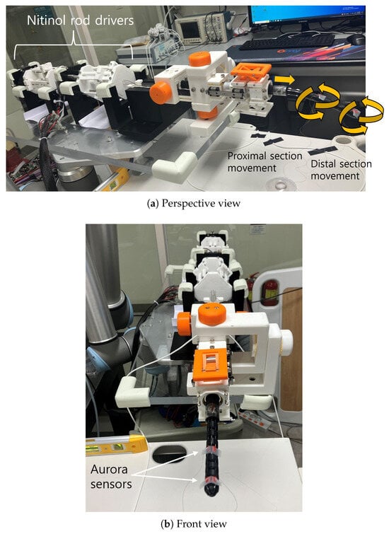
Figure 1.
Discrete continuum robot overview.
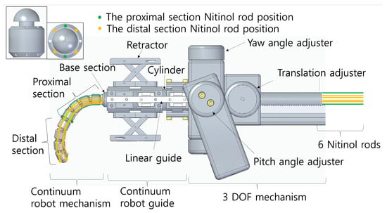
Figure 2.
Discrete continuum robot CAD image.
The discrete continuum robot comprises three parts, the continuum mechanism, the continuum guide, and the 3-DOF positioning mechanism, as shown in Figure 2. The continuum mechanism itself is divided into a distal section, a proximal section, and a base section. Both distal and proximal sections consist of four identical units, with their side and front views displayed in the upper left of Figure 2. Each unit is 20 mm in length and 15 mm in diameter, featuring a ball-and-socket joint with a radius of 5.5 mm, allowing for serial connection of multiple units. The theoretical maximum bending angle of a single unit is 20.0 degrees, yielding an overall maximum of 80.0 degrees for a four-unit section, with a combined section length of 60 mm. These design parameters are based on previous results [19].
The base section is a 300 mm long unit designed for insertion into the continuum guide (Figure 2) and connected to the translation adjuster for advancing and retracting motion. The total theoretical length of the distal and proximal sections combined is 120 mm, with a maximum overall bending angle of 160 degrees, satisfying the clinical specifications required by surgeons. When all eight units are assembled, six Nitinol rods are routed through the unit’s holes, as illustrated in Figure 2. Specifically, the green and yellow circles in Figure 2 indicate the proximal and distal section rod passageways, respectively. The Nitinol rods have a diameter of 0.89 mm and a modulus of elasticity of 60 GPa, according to the manufacturer’s specifications. The unit holes are 1.2 mm in diameter. The ends of the rods are anchored at the outermost body units of the distal and proximal sections, while the opposite ends are fixed to the ball screw mechanism of the rod drivers. As shown in Figure 2, the four rods in each section are positioned orthogonally (90 degrees apart), enabling 2-DOF bending in both sections. Note that two rods actuate the proximal section (green), while four rods actuate the distal section (yellow), allowing planar bending movements.
The continuum guide shown in Figure 2 consists of a retractor, a linear guide, and a cylinder. The retractor is designed to manually open the patient’s mouth by supporting the teeth and is mechanically linked to the linear guide to ensure stable linear translations. The 3-DOF mechanism allows manual yaw and pitch angle adjustment of the continuum mechanism and guide assembly by rotating their respective adjusters, while linear translation is enabled by a translation adjuster. The yaw and pitch mechanism has an angular resolution of 5 degrees, due to mechanical stoppers placed at every 5 degrees, while the translation mechanism has a screw pitch resolution of 0.5 mm. As indicated by the yellow arrows in Figure 1a, the entire developed robot system provides 7 DOF motion: 3 manual DOF from the positioning mechanism and 2 × 2 automatic DOF from the distal and proximal bending sections.
3. Planar Section Bending Control and Experimentally Induced Section Kinematics
For planar independent bending of each section, the six Nitinol rods depicted in Figure 2 (two for proximal actuation and four for distal actuation) must be properly coordinated. The control procedure for independent planar section bending is as follows:
- The six Nitinol rods are position-controlled.
- For planar distal section bending, the two upper (orange) and two lower Nitinol rods in the upper-left image of Figure 2 are paired and displaced by equal amounts. For upward bending, the upper rods are pulled (shortened) while the lower rods are released (elongated); the inverse occurs for downward bending.
- For planar proximal section bending, the green Nitinol rods in Figure 2 are symmetrically actuated with equal displacement. For upward bending, the upper rods are pulled (shortened) while the lower rods are released (elongated); the opposite occurs for downward bending.
- Because the four orange rods for distal actuation pass through the proximal section, an adjustment factor is required. During proximal actuation, the distal rods are displaced by of the proximal rod displacement, since
To establish the relationship between Nitinol rod displacement changes (, ) and section bending angles (, ), as well as to verify independent controllability under the proposed control method, a theoretical analysis is required. This involves modeling the superelastic Nitinol rods and solving the associated boundary value problem, which is currently being investigated by the authors in a separate study. In the present work, an experimental kinematic relationship based on distal and proximal section bending tests is developed to enable practical forward kinematics of the proposed robotic system and to complement the ongoing theoretical analysis.
In each experiment, the continuum robot and its six Nitinol rods (Figure 2) were initially set in a straight configuration with slight pre-tension applied to the rods. The results of the distal and proximal section bending tests are shown in Figure 3 and Figure 4, respectively.
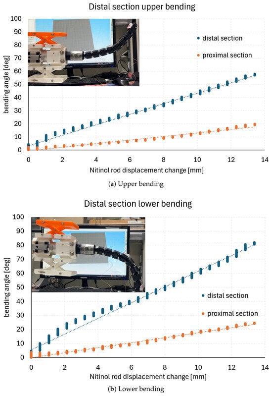
Figure 3.
Distal section bending test result.
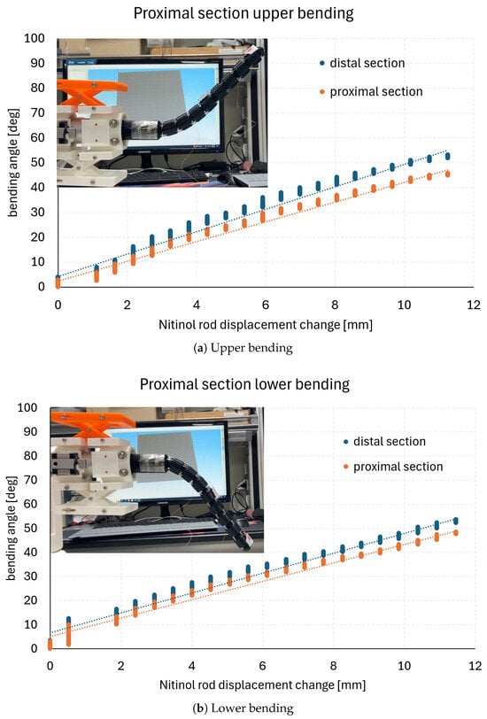
Figure 4.
Proximal section bending test result.
In the section bending tests, the Nitinol rod displacements (, ) were incrementally increased by 0.5 mm up to a maximum displacement of 12.5 mm. The corresponding section bending angles (, ) were measured at each increment using two electromagnetic tracking sensors (Aurora v2, NDI) mounted as shown in Figure 1b. The bending angles in Figure 3 and Figure 4 represent absolute angular changes with respect to the initial straight configuration of the robot. In the measurements, vertical variations are observed due to vibrations caused by incremental Nitinol rod movements. For data analysis, all measurement points were fitted as summarized in Table 1, with the fitting lines approximating the mean values at each displacement increment. Representative images of the final configurations corresponding to each graph are shown in the upper-left corners of Figure 3 and Figure 4.

Table 1.
Maximum bending angle and linear fitting results of section bending tests (total 12.5 mm Nitinol rod displacement change).
In Figure 3a,b, the proximal section bends simultaneously with the distal section. This occurs because the proximal section rods cannot maintain a straight configuration under the compressive forces induced by pulling the four distal section rods. The graphs in Figure 3 exhibit an approximately linear trend, with corresponding linear regression lines also plotted. For the proximal bending results in Figure 4a,b, the proximal and distal bending angles are nearly identical, with only minor discrepancies. The maximum bending angles in each case, along with the linear regression results, are summarized in Table 1. The average coefficient of determination of the linear fits is 0.98435. Nevertheless, slight nonlinearities are present, such as in the distal section lower bending shown in Figure 3b, which may affect configuration accuracy when experimentally derived kinematic relations are applied to the continuum robot.
4. Ansys Simulation of the Planar Distal Section Bending
A section bending test was conducted under the condition of a fixed proximal section, and a corresponding finite element method (FEM) analysis using ANSYS was performed under the same condition. By comparing the two results, the forward kinematics and the accuracy of motion control of the proposed robot were validated.
Forward kinematic analysis of the proposed Nitinol rod-driven discrete continuum robot is essential for verifying position control accuracy and validating section bending test results. To this end, FEM analysis was carried out under the same conditions as a section bending test described in Section 3, allowing experimental results to be compared directly with simulation outcomes. The selected bending test focused on evaluating the motion control of the four continuum units comprising the distal section, as illustrated in the upper-left corner of Figure 5a. In this test, the two upper Nitinol rods connected to the distal section were pulled to induce upward bending, and the corresponding angular changes in the continuum units were recorded as functions of rod displacement. To prevent displacement of the four proximal-section units connected to the base, a tubular block was fabricated via 3D printing and mounted externally around the proximal section. This ensured that the Nitinol rod displacement acted only on the distal section units. The experimental conditions were identical to those described in Section 3, and the resulting data are shown in Figure 5a.
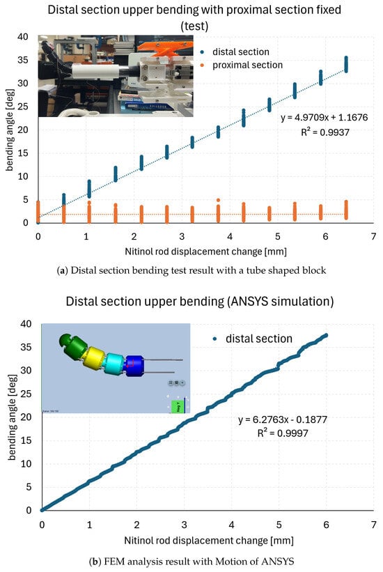
Figure 5.
Selected distal section bending test result for the comparison with the one of FEM analysis in ANSYS.
Because FEM analysis with time-domain boundary conditions is particularly time-consuming, the Nitinol rod displacement was increased in increments of 0.5 mm up to a total displacement of 6.0 mm. This was the only difference in boundary conditions compared with the experiments described in Section 3, enabling a smoother comparison. The FEM analysis was performed using the Motion module of ANSYS Workbench 2024 R2 on a dedicated PC (AMD Ryzen 9 7950X, 16 cores at 4.5 GHz, 128 GB RAM, Windows 11 Home). The four distal section units and their connecting Nitinol rods were modeled with dimensions identical to those of the experimental system.
All four Nitinol rods were modeled as flexible (superelastic NiTi), while the ball–socket unit bodies were modeled as rigid. A quasi-static analysis was adopted since bending behavior is dominated by the slender rods, and strains in the rigid unit bodies were negligible under the applied operating loads. Contacts and constraints were defined to transmit push–pull forces from the rods to the unit bodies; no large-deformation elasticity was assigned to the rigid sections.
This designation was justified because pulling the two upper Nitinol rods connected to the distal section did not produce geometric deformation in the unit bodies. Continuous upward pulling of the two rods was simulated using a step function in ANSYS, with a velocity of 0.5 mm/s to replicate the experimental setup. When the rod displacement reached 6.0 mm, the resulting continuum deformation is shown in the upper-left corner of Figure 5b. Considering that friction between the rods and their passage holes was minimal, a frictionless contact condition was applied in the model. Spherical joints were used at the interfaces between units, with experimentally derived static and dynamic friction coefficients of 0.4 and 0.28, respectively. To ensure stability, the lower end of the fourth unit was fixed. A marker function was employed to measure angular changes in each unit during rod displacement.
The combined model of the four distal units and rods consisted of 16,356 nodes and 18,634 elements. To achieve sufficient accuracy in the contact regions, a tetrahedral mesh was generated using the inflation function, particularly at the rod passage holes. Element sizes were 0.0004 for the unit hole surfaces (via face sizing) and 0.0005 for the Nitinol rods. Additional mesh refinement was applied along the rods and at every rod–unit contact interface to mitigate potential microslip. Unit bodies and links were meshed coarsely and treated as rigid under the quasi-static assumption.
At a maximum displacement of 6.0 mm, the experimental tests showed an angular change of approximately 32 degrees, while the FEM analysis predicted an angular change of approximately 37 degrees. The discrepancy is attributed primarily to friction effects between the Nitinol rods and their passage holes, which were neglected in the simulation. The linear regression of the experimental results yielded y = 4.9708x + 1.1676, with = 0.9937, and for the FEM analysis, y = 6.2763x- 0.1877, with = 0.9997. Considering experimental uncertainties and manufacturing tolerances, the two results are deemed closely aligned, thereby validating the proposed system’s forward kinematics and demonstrating high precision in motion control.
Since the FEM analysis with a time domain boundary condition is especially time-consuming, for smoother comparison, the Nitinol rod displacement was increased in increments of 0.5 mm until a total displacement of 6.0 mm was reached, which is the only difference in boundary conditions compared to the other experiments in Section 3. The FEM analysis was conducted using the Motion module of Ansys Workbench 2024 R2, installed on a dedicated PC (PC: AMD Ryzen 9 7950X 16-Core processor, 4.5 GHz, 128 GB RAM, Windows 11 Home). The four units of the distal section and the Nitinol rods connecting them were modeled with the same dimensions as the actual system.
5. Nitinol Rod-Driven Discrete Continuum Robot Path Planning Simulation
The designed discrete continuum robot must be validated for applicability in real clinical scenarios across diverse patient head and neck anatomies. To this end, path planning simulations were performed using reference passages generated from manually segmented patient CT images.
5.1. Two-Dimensional Reference Passage Construction by Manually Segmented CT Images
The dataset consisted of 10 CT scans obtained from The Cancer Imaging Archive (TCIA), specifically the Head-Neck-PET-CT dataset (https://www.cancerimagingarchive.net/collection/head-neck-pet-ct/, accessed on 3 September 2025). All images in this dataset were collected from four different institutions in Québec and included patients with histologically confirmed head and neck (H&N) cancer. From the full dataset, we manually selected 10 patients whose upper airway structures—including the oral cavity, nasal cavity, pharynx, and larynx—were clearly visible. Segmentation of the upper airway was performed through manual delineation on 2D axial slices using the image processing software 3D Slicer (http://www.slicer.org, accessed on 3 September 2025). To minimize subjectivity, the region of interest (ROI) was restricted strictly to the upper airway, and only voxels corresponding to air-intensity values were extracted, providing a more objective boundary criterion. In addition, all delineations were independently reviewed by two researchers, with final consensus reached after discussion. Although formal inter-rater reliability indices (e.g., Dice similarity coefficient or intraclass correlation coefficient (ICC)) were not computed due to the limited dataset size, this consensus-based review ensured internal consistency across all segmentations.
Using the point clouds of the head and neck airway derived from these segmented CT images, transnasal surgical passages from the lips to the nasopharyngeal tonsil via the soft palate were constructed based on clinical advice, as illustrated in Figure 6a–j. In each subfigure, three circles represent the continuum robot’s diameter and indicate the positions of the lips, the soft palate, and the nasopharyngeal tonsil from left to right. The lips and soft palate are connected by a straight line, and the soft palate and nasopharyngeal tonsil are connected by an arc, together forming the transnasal reference path. The geometric parameters of each passage are summarized in Table 2. The entrance angle in Table 2 is defined as the angle between the entry line segment and the horizontal axis, with positive values corresponding to counterclockwise rotation relative to the lip position. The measured entrance angles ranged from −2.6 degrees to 20.6 degrees. The total passage length, given in the fifth column of Table 2, ranged from 91.2 mm to 119.7 mm. As shown in Table 2, the entrance angle, line length, arc radius, and arc angle vary across patients, reflecting anatomical differences in individual head and neck structures.
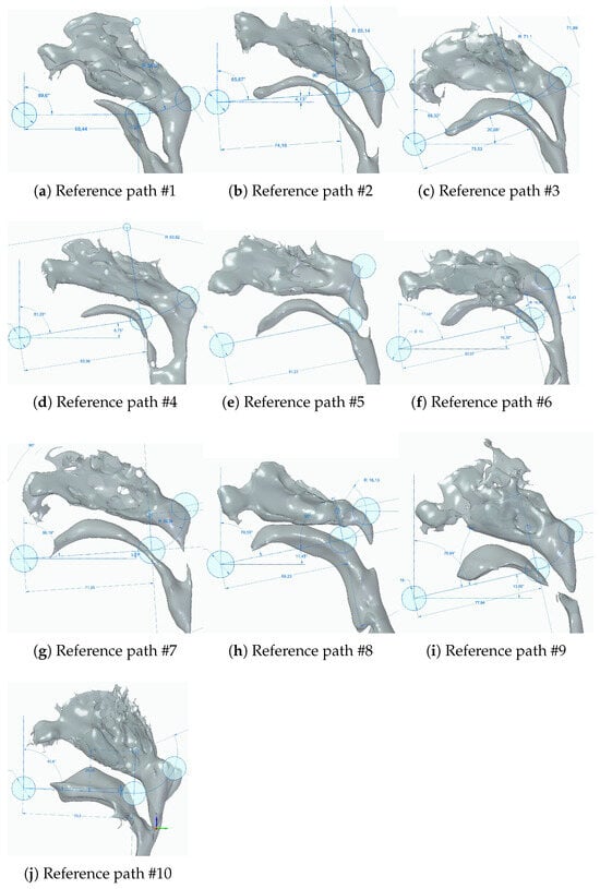
Figure 6.
Ten transnasal surgery passages from point clouds of head and neck anatomical cavity.
Table 2.
Geometric parameters of 10 reference passage (* NT: naspharyngeal tonsil).
5.2. Planar Path Planning Simulation with 2D Reference Passages
Using the reference passages shown in Table 2 and Figure 6a–j, optimal path planning was performed to evaluate the clinical feasibility of the designed discrete continuum robot mechanism. In the simulations, the bending angle of each section (Figure 1a,b and Figure 2) was controlled in 10% increments, ranging from −100% to 100% with a resolution of 10% (21 control inputs in total). A ± 100% control input corresponds to the maximum upward or downward bending of a section (±80 degrees). The distal and proximal sections were assumed to be controlled independently, resulting in 21 × 21 = 441 control input combinations. The initial position and orientation of the robot were defined as follows:
- The discrete continuum robot mechanism was aligned in a straight configuration.
- The tip of the distal section was positioned at the starting point of the reference path.
- The orientation of the robot was aligned with the entrance angle specified in Table 2.
From this initial posture, the robot mechanism was advanced in 3.75 mm increments until its total insertion length exceeded the reference passage length. At each increment, the optimal control combination was determined by evaluating all 441 control inputs and selecting the one that minimized the root mean square (RMS) error between the reference path and the robot configuration. The results of the path planning simulations are presented in Figure 7a–e and Figure 8a–e and a–e.
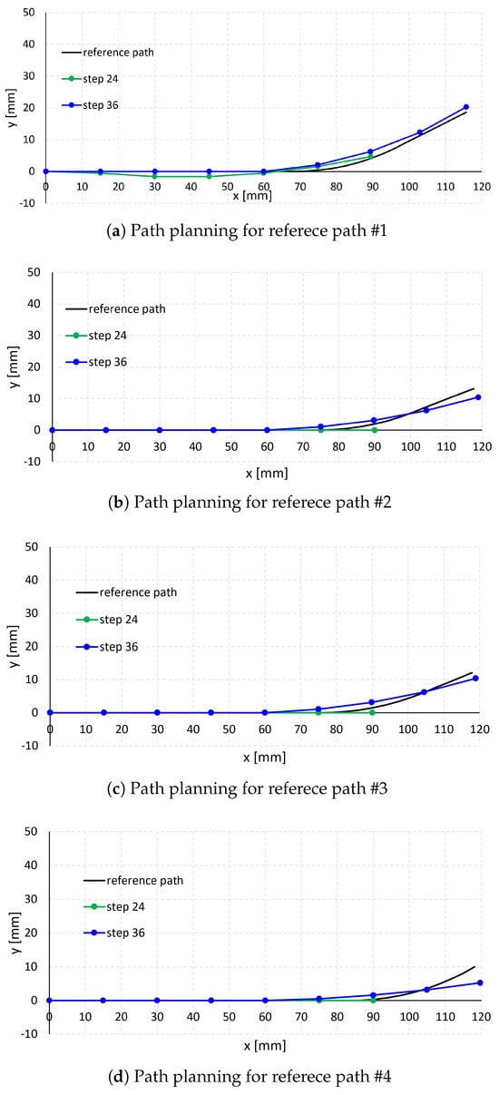
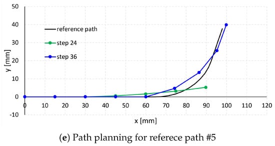
Figure 7.
Path planning simulation results (1).
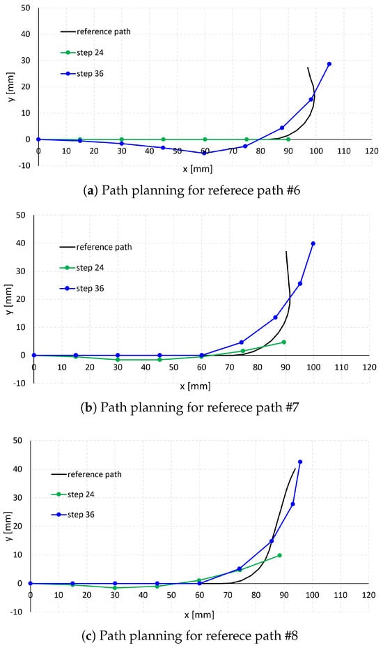
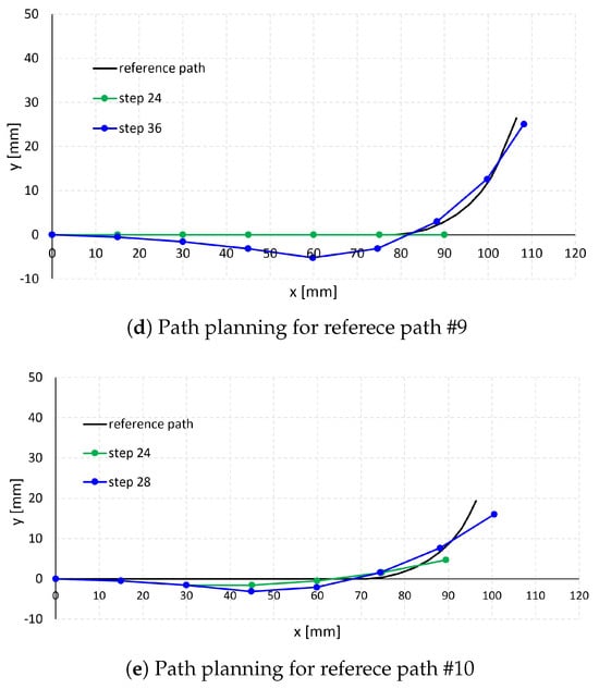
Figure 8.
Path planning simulation results (2).
In each subfigure of Figure 7 and Figure 8, the black curve represents the reference passage, while the green and blue curves represent the path planning results at steps 24 and 36 (step 28 for case #10 in Figure 6j), respectively. Steps 24, 28, and 36 correspond to robot insertion lengths of 90 mm, 105 mm, and 135 mm, respectively, calculated as 3.75 mm × step number. The dots along the green and blue curves indicate the positions of the unit endpoints.
As shown in cases #1–#5 in Figure 7a–e and cases #9–#10 in Figure 8d,e, when the reference paths have relatively large arc radii (26.4–71.1 mm in Table 2) and small arc angles (25.5–76.3 degrees in Table 2), the robot follows the paths effectively. In contrast, for reference paths with smaller arc radii (16.1–20.3 mm in Table 2), such as cases #6–#8 in Figure 8a–c, and larger arc angles (78.3 −114.5 degrees in Table 2), the robot exhibits larger path-following errors, particularly along the curved arc segments. This is attributed to the bending angle per unit length of the robot section, calculated as 80 degrees/(15 mm × 4) = 1.3 degrees/mm, which is smaller than the arc angle per unit length of passages #6–#8 (3.49 degrees/mm, 2.82 degrees/mm, and 3.55 degrees/mm, respectively).
Table 3 summarizes the optimal control inputs at steps 24 and 36 (28 for case #10). Notably, negative proximal control inputs were observed at these steps, resulting in convex distal section configurations, as illustrated in cases #6, #9, and #10 in Figure 6f,i,j. These convex configurations allow the robot to better follow the arc segments of the reference paths, albeit at the expense of slightly higher RMS error along the linear segments. Because overall RMS error was minimized compared with configurations using only positive inputs, this control strategy was selected as optimal.
Table 3.
Optimal control input at step 24 and 36 [%].
Table 4 presents the RMS error values between the reference paths and the optimal robot configurations at steps 24 and 36 (28 for case #10), calculated as the position difference between the reference path and robot configuration at each 3.75 mm increment along the robot’s longitudinal displacement. The average RMS error across the 10 reference paths was 0.89 mm at step 24 and 1.97 mm at step 36 (28). These values, both below 2 mm, are considered clinically acceptable and unlikely to cause significant damage to the oral cavity during practical surgical use.
Table 4.
RMS of position difference between the reference path and the optimal robot configuration [mm].
6. Nitinol Rod-Driven Discrete Continuum Robot Path Planning Test
Path planning tests were conducted using the experimentally induced kinematics of the discrete continuum robot and the control sequences derived from the simulations. Three segmented 3D transoral cavity models—#1, #3, and #10 from Figure 6a,c,j—were selected for testing, as these cases have non-disconnected anatomical structures and can be 3D-printed for future in vitro transoral passage experiments. The path planning test results are presented in Figure 9a–c. In each subfigure, the left table shows the control numbers at each step and the expected distal and proximal bending angles, consistent with the simulation predictions in Table 3. The robot was actuated in four-control-step increments until the final step was reached, as described in the first column of the tables in Figure 9a–c.
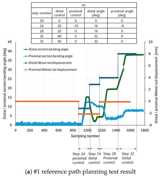
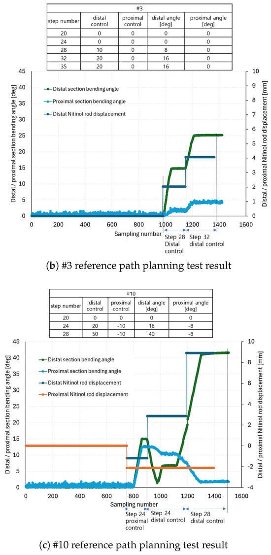
Figure 9.
The #1, #3, and #10 reference path planning test results.
The graphs in Figure 9a–c show the distal and proximal section bending angles and the corresponding Nitinol rod displacements. At each control step listed in the tables, proximal control was applied following procedures 3–4 in Section 3, followed by distal control according to procedure 2. The Nitinol rod displacements at each control step were calculated by multiplying the expected distal and proximal bending angles (columns 4 and 5 in the tables of Figure 9a–c by the reciprocal of the linear fitting slopes in Table 1. Positive displacement values correspond to positive control inputs, and negative values to negative control inputs. Note that the measured bending angles in the graphs of Figure 9a–c are always presented as positive, as they represent absolute changes from the initial configuration, calculated using quaternion measurements from the electromagnetic tracking system sensors (Aurora v2, NDI). The x-axes in the graphs indicate sampling number, and control step annotations are indicated for readability.
As an example, in Figure 9a at step 24 during proximal actuation, the distal and proximal rods were displaced to −1.18 mm and −2.12 mm, corresponding to a −10 proximal control input. This resulted in distal and proximal bending angles of −15.24 and −12.53 degrees, respectively. At step 24, distal actuation, the distal rods were displaced by 2.86 mm (from −1.18 mm), bending the distal section upward by 20 control input units. Consequently, the distal angle changed from −15.24 to 4.34 degrees, while the proximal angle shifted from −12.53 to −10.15 degrees. At step 28, proximal control, the rod displacements reached 3.99 mm and 0 mm, producing distal and proximal angles of 19.52 and −3.49 degrees, respectively. Finally, at step 32, distal control, the distal rods reached 8.02 mm displacement, resulting in distal and proximal bending angles of 38.08 and 7.70 degrees. Notably, even in the absence of active proximal control, the proximal section bent in response to distal section actuation, consistent with the coupled behavior observed in Figure 3a,b. Similar analyses were carried out for Figure 9b,c. The expected vs. measured angles at each step are summarized in Table 5.
Table 5.
Path planning test results (* abs. diff.: absolute difference).
In Table 5 and the paragraph above, the symbol (–) indicates downward bending, attached to positive absolute angle measurements in Figure 9a–c. The absolute differences between the expected and measured distal and proximal angles were then computed. On average, differences of 5.6 degrees for the distal section and 4.1 degrees for the proximal section were achieved. Figure 10a–c shows snapshots of the reference path-following test at the end of each control step, corresponding to the arrows in Figure 9a–c. These subfigures can also be compared directly with the simulation results in Figure 7a–c and Figure 8e.
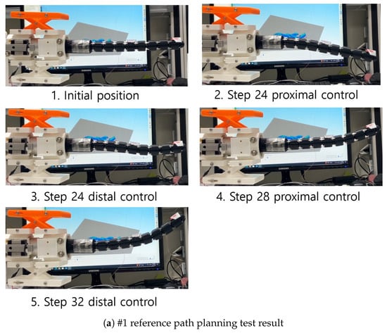
Figure 10.
Snapshots of #1, #3, and #10 reference path planning tests.
7. Conclusions and Discussions
In this paper, a Nitinol rod-driven discrete continuum robot prototype was developed for transoral surgery assistance. The system consists of a continuum mechanism with two sections and eight units, a continuum guide, and a 3-DOF positioning mechanism. Each section is actuated planarly by Nitinol rods (six rods in total). To preliminarily validate the planar bending capability, proximal and distal section bending tests were performed. Furthermore, forward kinematics and motion-control precision of the proposed system were evaluated using a finite element method (FEM) analysis in ANSYS Motion, and the results were compared with experiments performed under identical boundary conditions.
Using the developed discrete continuum robot, planar path-planning simulations were carried out with reference passages reconstructed from manually segmented CT images of 10 patients. The results showed an average RMS positional error of 1.97 mm. Path-planning experiments with the fabricated robot further validated the simulations; the average absolute differences between simulated and experimental distal and proximal angles were 5.6 and 4.1 degrees, respectively.
Recent studies on continuum robots report tracking accuracy ranging from sub-millimeters to a few millimeters, depending on control, sensing, and medium. For example, in a maxillary sinus phantom, Cao et al. [27] achieved a mean error of 0.96 mm using an iterative Jacobian–transpose controller. Data-driven identification of tendon-driven arms by Parvaresh et al. [28] achieved per-axis RMSE of 0.83–0.87 mm on experimental datasets. Prior closed-loop controllers in related configurations report tracking errors of 2.8 mm on small-radius paths. The average RMS error of our prototype (<2 mm) therefore falls within the reported range of preliminary continuum systems. Comprehensive performance metrics—such as dexterity, exertable force, and robustness in tissue interactions—will be evaluated in future studies.
Limitations and Future Work:
- The robot was validated through path-planning experiments using experimentally induced kinematics and the control sequences derived from simulations. While the results are sufficient to demonstrate feasibility for master–slave operation in clinical settings, the experimentally induced kinematics in Table 1 do not precisely represent the true section kinematics. Future work will establish a theoretical relationship between Nitinol rod displacements and section bending angles to enable more accurate and automated control. Extending planar inverse kinematics to 3D inverse kinematics using four rods must also be pursued for future 3D navigation.
- Several design parameters significantly influence the independent controllability of each section:
- (a)
- As noted in Section 3, when the number of actuating rods differs between proximal and distal sections, proximal bending occurs unintentionally during distal actuation due to compressive forces transmitted through the rods. Therefore, for stable independent planar bending, the number of rods in both sections should be equal.
- (b)
- The eight holes through which the 0.89 mm Nitinol rods pass (Figure 2) have a diameter of 1.2 mm, leaving a clearance of 0.31 mm. This clearance has an important influence on the rod displacement-to-bending angle characteristics described in Section 3, as friction between the rods and hole edges induces additional tensile forces and elongation. Optimizing hole diameter is therefore necessary to minimize friction and maximize section bending efficiency.
- In the current prototype, the 3-DOF positioning mechanism is manually actuated via yaw, pitch, and translation adjusters (Figure 2). For precise robot control, this mechanism should be motorized. Motorization, combined with appropriate actuator gear mechanisms, would significantly enhance resolution and repeatability.
- Path planning was validated using CT images from only 10 patients selected from a publicly available dataset. While this sufficed to demonstrate feasibility, the small dataset does not capture the full anatomical variability of head and neck structures. Broader validation with larger and more diverse patient cohorts is required to generalize the findings to clinical settings.
- In this study, a rigid-module assumption was employed under the current load range, as section stiffness was dominant. Future work will extend FEM analysis to fully flexible modules and quantify compliance through mesh- and parameter-sensitivity studies. A systematic mesh-convergence (h-refinement) analysis will also be performed when investigating higher loads or strongly nonlinear regimes.
Author Contributions
Conceptualization and design, Y.-J.K., J.E.O. and D.W.; methodology, Y.-J.K., J.E.O. and D.W.; data collection, Y.-J.K., J.E.O. and D.W.; analysis and interpretation, Y.-J.K., J.E.O. and D.W.; writing the article, Y.-J.K., J.E.O. and D.W.; critical revision, Y.-J.K., J.E.O. and D.W.; final approval of the article, Y.-J.K., J.E.O. and D.W. All authors have read and agreed to the published version of the manuscript.
Funding
This work was supported by a National Research Foundation of Korea (NRF) grant funded by the Korea government (MSIT) (No. RS-2021-NR061860, No. 2020R1C1C1012905, and No. 2021R1C1C2006999).
Data Availability Statement
The data that support the findings of this study are available from the corresponding author upon reasonable request. The data are not publicly available due to their volume and the absence of a public repository submission.
Conflicts of Interest
The authors declare no conflicts of interest.
References
- Gormley, M.; Creaney, G.; Schache, A.; Ingarfield, K.; Conway, D.I. Reviewing the epidemiology of head and neck cancer: Definitions, trends and risk factors. Br. Dent. J. 2022, 233, 780–786. [Google Scholar] [CrossRef]
- Van Abel, K.M.; Yin, L.X.; Price, D.L.; Janus, J.R.; Kasperbauer, J.L.; Moore, E.J. One-year outcomes for da Vinci single port robot for transoral robotic surgery. Head Neck 2020, 42, 2077–2087. [Google Scholar] [CrossRef]
- Hussain, T.; Lang, S.; Haßkamp, P.; Holtmann, L.; Höing, B.; Mattheis, S. The Flex robotic system compared to transoral laser microsurgery for the resection of supraglottic carcinomas: First results and preliminary oncologic outcomes. Eur. Arch. Oto-Rhino-Laryngol. 2020, 277, 917–924. [Google Scholar] [CrossRef]
- Sethi, N.; Gouzos, M.; Padhye, V.; Ooi, E.H.; Foreman, A.; Krishnan, S.; Hodge, J.C. Transoral robotic surgery using the Medrobotic Flex® system: The Adelaide experience. J. Robot. Surg. 2020, 14, 109–113. [Google Scholar] [CrossRef] [PubMed]
- Gu, X.; Li, C.; Xiao, X.; Lim, C.M.; Ren, H. A Compliant Transoral Surgical Robotic System Based on a Parallel Flexible Mechanism. Ann. Biomed. Eng. 2019, 47, 1329–1344. [Google Scholar] [CrossRef] [PubMed]
- Li, C.; Gu, X.; Xiao, X.; Lim, C.M.; Ren, H. Compliant and Flexible Robotic System with Parallel Continuum Mechanism for Transoral Surgery: A Pilot Cadaveric Study. Robotics 2022, 11, 135. [Google Scholar] [CrossRef]
- Li, C.; Gu, X.; Xiao, X.; Lim, C.M.; Ren, H. Cadaveric feasibility study of a teleoperated parallel continuum robot with variable stiffness for transoral surgery. Med. Biol. Eng. Comput. 2020, 58, 2063–2069. [Google Scholar] [CrossRef]
- Hu, Z.; Li, J.; Wang, S. Design and Kinematics of a Robotic Instrument for Natural Orifice Transluminal Endoscopic Surgery. IEEE/ASME Trans. Mechatronic 2023, 28, 2840–2851. [Google Scholar] [CrossRef]
- Luo, H.; Ding, J.; Wang, S. A master-slave robot system for minimally invasive laryngeal surgery. In Proceedings of the 2009 IEEE International Conference on Robotics and Biomimetics (ROBIO), Guilin, China, 19–23 December 2009; pp. 782–787. [Google Scholar] [CrossRef]
- Simaan, N.; Xu, K.; Wei, W.; Kapoor, A.; Kazanzides, P.; Taylor, R.; Flint, P. Design and Integration of a Telerobotic System for Minimally Invasive Surgery of the Throat. Int. J. Robot. Res. 2009, 28, 1134–1153. [Google Scholar] [CrossRef]
- Wang, H.; Wang, X.; Yang, W.; Du, Z. Design and Kinematic Modeling of a Notch Continuum Manipulator for Laryngeal Surgery. Int. J. Control Autom. Syst. 2020, 18, 2966–2973. [Google Scholar] [CrossRef]
- Feng, F.; Zhou, Y.; Hong, W.; Li, K.; Xie, L. Development and experiments of a continuum robotic system for transoral laryngeal surgery. Int. J. Comput. Assist. Radiol. Surg. 2022, 17, 497–505. [Google Scholar] [CrossRef] [PubMed]
- Berthet-Rayne, P.; Leibrandt, K.; Gras, G.; Fraisse, P.; Crosnier, A.; Yang, G.Z. Inverse Kinematics Control Methods for Redundant Snakelike Robot Teleoperation During Minimally Invasive Surgery. IEEE Robot. Autom. Lett. 2018, 3, 2501–2508. [Google Scholar] [CrossRef]
- Zhao, M.; Vrielink, T.J.C.O.; Kogkas, A.A.; Runciman, M.S.; Elson, D.S.; Mylonas, G.P. LaryngoTORS: A Novel Cable-Driven Parallel Robotic System for Transoral Laser Phonosurgery. IEEE Robot. Autom. Lett. 2020, 5, 1516–1523. [Google Scholar] [CrossRef]
- Shi, Y.; Lou, Y.; Shirai, I.; Wu, X.; Paydarfar, J.A.; Halter, R.J. Surgical navigation system for image-guided transoral robotic surgery: A proof of concept. In Proceedings of the Medical Imaging 2022: Image-Guided Procedures, Robotic Interventions, and Modeling, San Diego, CA, USA, 20 February–28 March 2022; SPIE: Bellingham, WA, USA, 2022; Volume 12034, pp. 43–48. [Google Scholar] [CrossRef]
- Kim, S.H.; Seo, J.T.; Woo, J.H.; Yoon, H.S.; Tae, K.; Yi, B.J. System Design and Experiment of a Laryngeal Surgical Robotic System. In Proceedings of the 2018 15th International Conference on Ubiquitous Robots (UR), Honolulu, HI, USA, 26–30 June 2018; pp. 44–47. [Google Scholar] [CrossRef]
- Friedrich, D.T.; Modes, V.; Hoffmann, T.K.; Greve, J.; Schuler, P.J.; Burgner-Kahrs, J. Teleoperated tubular continuum robots for transoral surgery - feasibility in a porcine larynx model. Int. J. Med. Robot. Comput. Assist. Surg. MRCAS 2018, 14, e1928. [Google Scholar] [CrossRef]
- Hong, W.; Zhou, Y.; Cao, Y.; Feng, F.; Liu, Z.; Li, K.; Xie, L. Development and validation of a two-segment continuum robot for maxillary sinus surgery. Int. J. Med. Robot. Comput. Assist. Surg. 2022, 18, e2340. [Google Scholar] [CrossRef]
- Kim, Y.J.; Choi, J.; Choi, J.; Moon, Y. Genetic Algorithm-based Discrete Continuum Robot Design Methodology for Transoral Slave Robotic System. Int. J. Control. Autom. Syst. 2022, 20, 3361–3371. [Google Scholar] [CrossRef]
- Kim, Y.J.; Hyun, J.H.; Lee, D.H.; Yang, B.M.; Choi, J.E.; Choi, J.S.; Moon, Y.J. Preliminary design of the continuum robot module with the ball-socket joint in the development of transoral surgery robot. In Proceedings of the 19th International Conference on Control, Automation, and Systems (ICCAS 2019), Jeju, Republic of Korea, 15–18 October 2019. [Google Scholar]
- Kim, Y.J.; Wi, D. Planar Inverse Statics and Path Planning for a Tendon-Driven Discrete Continuum Robot. Robotics 2025, 14, 91. [Google Scholar] [CrossRef]
- Chen, J.; Yan, J.; Qiu, Y.; Fang, H.; Chen, J.; Cheng, S.S. A Cross-Entropy Motion Planning Framework for Hybrid Continuum Robots. IEEE Robot. Autom. Lett. 2023, 8, 8200–8207. [Google Scholar] [CrossRef]
- Meng, B.H.; Godage, I.S.; Kanj, I. RRT*-Based Path Planning for Continuum Arms. IEEE Robot. Autom. Lett. 2022, 7, 6830–6837. [Google Scholar] [CrossRef]
- Niu, G.; Zhang, Y.; Li, W. Path Planning of Continuum Robot Based on Path Fitting. J. Control Sci. Eng. 2020, 2020, e8826749. [Google Scholar] [CrossRef]
- Seleem, I.A.; El-Hussieny, H.; Ishii, H. Imitation-based Path Planning and Nonlinear Model Predictive Control of a Multi-Section Continuum Robots. J. Intell. Robot. Syst. 2023, 108, 9. [Google Scholar] [CrossRef]
- Seleem, I.A.; Assal, S.F.M.; Ishii, H.; El-Hussieny, H. Demonstration-Guided Pose Planning and Tracking for Multi-Section Continuum Robots Considering Robot Dynamics. IEEE Access 2019, 7, 166690–166703. [Google Scholar] [CrossRef]
- Cao, Y.; Liu, Z.; Liu, Z.; Wang, S.; Xie, L. Design and path tracking control of a continuum robot for maxillary sinus surgery. Int. J. Comput. Assist. Radiol. Surg. 2023, 18, 753–761. [Google Scholar] [CrossRef]
- Parvaresh, A.; Moosavian, S.A.A. Dynamics and path tracking of continuum robotic arms using data-driven identification tools. Robotica 2022, 40, 1098–1124. [Google Scholar] [CrossRef]
Disclaimer/Publisher’s Note: The statements, opinions and data contained in all publications are solely those of the individual author(s) and contributor(s) and not of MDPI and/or the editor(s). MDPI and/or the editor(s) disclaim responsibility for any injury to people or property resulting from any ideas, methods, instructions or products referred to in the content. |
© 2025 by the authors. Licensee MDPI, Basel, Switzerland. This article is an open access article distributed under the terms and conditions of the Creative Commons Attribution (CC BY) license (https://creativecommons.org/licenses/by/4.0/).