Article

Improving Rover Path Planning in Challenging Terrains: A Comparative Study of RRT-Based Algorithms

James Watt School of Engineering, University of Glasgow, Glasgow G12 8QQ, UK
*
Author to whom correspondence should be addressed.
Robotics 2025, 14(10), 135; https://doi.org/10.3390/robotics14100135
Submission received: 18 August 2025 / Revised: 18 September 2025 / Accepted: 22 September 2025 / Published: 26 September 2025
(This article belongs to the Section Aerospace Robotics and Autonomous Systems)

Abstract

Autonomous planetary rovers require robust path planning over rough 3D terrains, where traditional metrics such as path length, number of nodes, and planning time do not adequately capture path quality. Rapidly Exploring Random Trees (RRT) and its asymptotically optimal variant, RRT*, are widely used sampling-based algorithms for non-holonomic mobile robots but are limited when traversing uneven 3D terrain. This study proposes 3D-RRT*, a simplified, terrain-aware extension of Traversability-Based RRT*, designed to maintain high path quality while reducing planning time. The performance of 3D-RRT* is evaluated using metrics that are both practical and meaningful in the context of planetary rover path planning: path smoothness, path flatness, path length, and planning time. Exploration of a simulated Martian surface demonstrates that 3D-RRT* significantly improves path quality compared to standard RRT and RRT*, achieving smoother, safer, and more efficient routes for planetary rover missions.

1. Introduction

Throughout the 20th and 21st centuries, planetary-exploration missions have expanded humanity’s knowledge and understanding of the solar system, offering insights into phenomena such as Venus’ greenhouse effect and Martian dust storms that inform our understanding of the future of Earth’s environment [1]. Resulting space technologies have also generated wider benefits, with applications in fields such as medical imaging [2] and telemedicine [3]. However, the physical and psychological risks of deep-space travel make human-led missions highly challenging [4]. To bridge this gap, planetary-exploration rovers (PERs) serve as essential precursors, playing a pivotal role in advancing technological innovation and expanding scientific knowledge in locations that are currently inaccessible to manned missions [5]. In practice, PERs undertake a wide range of activities, from acquiring and caching geological samples to monitoring environmental conditions and conducting in-situ analysis [6,7]. These tasks must be accomplished with high levels of autonomy due to limited communication windows and significant signal delays [8]. Among the principal challenges faced in PER missions are ensuring safe and efficient path planning across challenging terrains [9], alongside maintaining functionality through robust fault diagnosis and recovery mechanisms [10,11,12]. The critical role of path planning in enabling these operations is explored within this study.
Planetary-exploration rovers (PERs) operate in hostile environments characterised by rough and uneven terrain. To navigate effectively, PERs must plan paths that are both safe, i.e., avoiding obstacles and respecting mobility limits, and efficient [13]. In practice, PER path planning is a multi-stage process involving perception, planning, and execution. Environmental information is first acquired through sensors and converted into a traversability map. An appropriate path is then generated and executed by the rover, with its progress monitored to detect deviations caused by slip, terrain uncertainties, or new obstacles. These monitoring steps are essential for safe and autonomous operation, particularly under the communication delays inherent to planetary missions. The growing reliance on autonomous navigation, driven by the impracticality of real-time teleoperation due to communication delays [8], places even greater emphasis on developing path planners that can adaptively balance safety and efficiency without human intervention.
Selecting appropriate path planning for PERs requires careful consideration of performance metrics. Classical metrics, such as path length, computational runtime, and the number of nodes explored, have been widely used. However, recent work by Mūnoz et al. challenges their relevance for planetary-exploration contexts [14]; for example, since PER path planning can often be performed offline as part of strategic route planning, real-time computational efficiency becomes less critical. Furthermore, while minimising path length is effective in 2D environments, in 3D terrains with slopes and rough surfaces, the shortest path may not be the most easily traversed (Figure 1). In such conditions, rough terrain can significantly degrade path following and mission success. Consequently, new path-planning metrics that consider terrain characteristics and rover capabilities are needed. Metrics such as path smoothness (minimising excessive turning) and path flatness (favouring gentler slopes) offer more meaningful indicators of path quality for PERs [14,15].
This study addresses the scientific gap between traditional path-planning metrics and the practical demands of planetary exploration. The primary contributions are:
  • The introduction of 3D-RRT*, an extension of the RRT* algorithm that directly incorporates terrain slope into its cost function.
  • A comprehensive comparison of RRT-based planners using terrain-aware metrics, demonstrating the effectiveness of the 3D-RRT* algorithm through simulation experiments in a 3D Martian environment.
The proposed 3D-RRT* builds on Traversability-Based RRT*, but simplifies the planning process by directly incorporating terrain slope into the cost function, rather than explicitly modelling the detailed dynamics and kinematics of a specific rover. This generalisation not only maintains high path quality across varied terrains but also reduces computational complexity, enabling faster path generation. As a result, 3D-RRT* is particularly well suited for multi-robot teams, where online planning is often required to respond to dynamic changes such as newly detected obstacles, including other robots, or the failure of team members. Furthermore, because 3D-RRT* does not rely on platform-specific dynamics, it can more easily accommodate heterogeneous robot teams, providing a flexible and scalable solution for cooperative planetary-exploration missions.
This paper compares several RRT-based planners, including RRT, RRT*, Traversability-Based RRT*, and the proposed 3D-RRT*, using terrain-aware metrics: path length, path smoothness, and path flatness, alongside planning time. Algorithms are evaluated in a simulated 3D Martian environment with 2.5D traversability mapping. This study demonstrates that path quality improves significantly with terrain-aware metrics, and that 3D-RRT* appears to maintain path quality while reducing planning time compared to Traversability-Based RRT*.
The exploration of various RRT-based path-planning methods is presented in this paper as follows. Section 2 discusses related work, including the challenges associated with path planning for planetary-exploration rovers and the application of RRT and its algorithmic variants. Section 3 describes the four RRT-based sampling algorithms considered within this work: RRT, RRT*, Traversability-Based RRT*, and 3D-RRT*. Section 4 sets out the mathematical model of an appropriate rover platform, which is used to enable a comparison of the four RRT based path planners, as well as discussing the 3D Martian terrain model used within the simulation and associated traversability analysis. The results of the simulation experiments carried out are presented in Section 5. A discussion of these results and their wider implications is given in Section 6. Finally, Section 7 outlines the outcomes and conclusions of the work.

2. Related Work

2.1. Challenges of Path Planning for Planetary-Exploration Rovers

Path planning for planetary exploration presents numerous challenges due to the unique environmental conditions found on Mars and the Moon. One of the primary difficulties is navigating rough and unpredictable terrain, which can hinder a rover’s ability to accurately follow a planned path due to the risk of slip. Ishigami et al. demonstrated how slip on sloped terrain affects rover locomotion and proposed a slip compensation method that significantly reduces both positional and orientation errors in path execution [16]. In subsequent work, the same authors evaluated potential paths based on terrain roughness, path length, and inclination, finding that applying inclination thresholds can help minimise pitch and roll variation—thereby reducing the likelihood of slip [17]. Thus, incorporating terrain features such as inclination thresholds into path-planning strategies is a crucial step toward improving rover mobility and navigation accuracy in rough terrains.
To enable a rover to plan a safe and efficient path, a comprehensive understanding of the operational environment is essential. While human operators have traditionally classified terrain within maps, significant research has focused on autonomous terrain classification and mapping techniques to support on-board autonomy. Several methods have been proposed to generate and utilise these maps. 2.5D traversability maps, which are elevation maps with additional data layers representing terrain characteristics, are particularly relevant [18]. These maps encode features such as slope and roughness, enabling traversability analysis [19]. The use of such maps allow path planners to optimise paths based on terrain specific costs, ensuring both safety and efficiency [13]. For example, cost maps can be generated using data from terrain that is analogous to that of the Moon or Mars, enabling traversability analysis based on factors such as obstacle proximity and orientation [20]. Similarly, learning-based terrain classifiers can integrate with path-planning software to autonomously classify different terrain types and generate safe paths [21].
The above challenges are compounded by the inherent kinematic limits of rover platforms. Many planetary rover platforms have adopted rocker–bogie suspension systems with six wheels, providing robust ground clearance and mobility [22]. For NASA’s Mars Exploration Rovers, JPL required at least 20 cm ground clearance and 45 ° static stability, with dynamic stability further limiting the slopes that could be safely traversed [23]. In practice, Opportunity and Curiosity achieved maximum climbs of 32 ° and 31 ° , though nominal operations remain within ± 15 ° pitch and roll [24]. Studies of slope traversal also report slip rates of around 1% per degree on sandy slopes between 10–20°, underscoring the contribution of kinematic limits in planning feasible paths [25].
In addition to above-mentioned challenges, communication delays present a fundamental constraint on path planning for planetary exploration [8]. These inherent delays between Earth and planetary-exploration mission sites render real-time teleoperation infeasible, thereby necessitating a high degree of autonomy in PERs [24]. Over successive missions, NASA has progressively integrated more advanced autonomous planning capabilities to address this need. The Sojourner rover employed a reactive navigation system, relying on stereo vision and laser ranging to detect and avoid obstacles without constructing a persistent terrain map [26]. Subsequent missions, including Spirit and Opportunity, introduced enhanced autonomy by generating local traversability maps and adopting global path planners such as Field D* [27]. The Curiosity rover further advanced this capability, utilising a variant of the D* algorithm to identify globally optimal paths [28,29]. Most recently, the Perseverance rover has demonstrated a substantial leap in autonomous navigation, achieving record-breaking distances in continuous autonomous driving and significantly surpassing its predecessors in average distance travelled per sol [30,31]. These advancements underscore the critical role of onboard autonomy in enabling robust and efficient path planning and navigation under the communication constraints of planetary missions.
Beyond terrain and autonomy challenges, planetary rovers must also operate under strict power constraints, meaning that path planning must balance not only safety and efficiency but also the power consumption associated with traversing steep slopes or extended detours [32]. Importantly, the power systems implemented in real missions often differ substantially from those modelled in laboratory studies or simulations. To better capture the implications of these limitations for path planning, studies in planetary analogue environments have been conducted to bridge the gap between simplified experimental power models and the more complex systems deployed in planetary-exploration missions [33]. Alternatively, power constraints can be addressed by incorporating energy considerations into mission site maps [34], or by explicitly integrating power consumption into the path cost function [35].

2.2. RRT-Based Path-Planning Algorithms

Originally developed by LaValle [36], the Rapidly Exploring Random Tree (RRT) algorithm provides a randomised data structure for solving motion-planning problems, particularly for non-holonomic vehicles. Its strengths include a strong bias toward unexplored regions, probabilistic completeness, and guaranteed connectivity of nodes. Building on this foundation, Karaman and Frazzoli proposed RRT*, which introduces asymptotic optimality, meaning that as the tree grows, the solution cost converges to the optimal value [37]. The RRT algorithm can be further extended to adjust the quality of the output to suit a given application. Two commonly extended features of RRT are growth biasing and path smoothing. The growth of an RRT can be heuristically biased to guide the tree towards a goal and/or away from high cost areas [38]. The latter case is particularly useful in mobile robotics applications, where the operational environment may contain many terrain types. Urmson and Simmons showed that, by introducing terrain heuristics, the quality of paths generated by an RRT in a variable cost space with obstacles can be significantly improved [38]. However, any artificial biases applied to the algorithm must be carefully considered. For example, a bias towards the goal that is too strong could result in a search which gets caught in local minima [36].
Several variants of RRT-based path-planning algorithms have been specifically developed and applied in the context of planetary exploration. Sampling-based approaches such as Bi-RRT and its extension Bi-RRT-APF have been employed to enhance path-planning efficiency in complex terrains [39,40]. Hybrid methods, including Rapidly exploring Random Graph-A* (RRG-A*), have combined the benefits of graph-based search and sampling techniques to improve solution optimality and computational robustness in unstructured environments [21]. To address the challenges posed by uneven 3D planetary surfaces, traversability-aware adaptations of RRT*, such as the one proposed in [15], incorporate terrain features like smoothness and flatness into the planning process. Moreover, the authors’ recent work has extended the use of RRT*-based planners to multi-robot systems for cooperative planetary exploration, enabling more efficient and safe exploration strategies [13,41].
These advancements demonstrate that RRT-based algorithms offer a suitable framework for addressing the unique challenges of planetary exploration, including rough terrain, and computational constraints. The ability to incorporate terrain-aware heuristics and support multi-agent coordination makes RRT-based path planners well-suited for future autonomous planetary-exploration rovers.
In recent years, a variety of new RRT extensions have been proposed to improve convergence speed and path quality. The quadRRT algorithm addresses the issues of low computational efficiency often exhibited by sampling-based planners by improving processing time using a multi-directional search strategy via a modern GPU [42]. To accelerate convergence speed, often an issue with sampling-based planners, recent research has combined convolutional neural networks with RRT* (NRRT*) [43]. The F-RRT* algorithm also addresses the issue of convergence, as well as the effect of initial conditions, generating an improved path via a novel parent-node selection strategy and light-weight node-creation procedures [44]. The RDT-RRT algorithm has been introduced to address the ability of RRT based planners to provide real time planning solutions in dynamic environments [45]. These approaches highlight the breadth of ongoing developments in the field of sampling-based path planning. However, these approaches have not yet been widely applied to planetary exploration, where terrain-aware planning is more critical. For this reason, the present study focuses on comparing RRT, RRT*, Traversability-Based RRT* and the newly proposed 3D-RRT*, which directly addresses the unique challenges of rover mobility in rough, sloped terrains.
It is worth noting that, beyond RRT-Based algorithms, a range of approaches have been explored for PER path planning. Biologically inspired algorithms, such as the comprehensive genetic algorithm proposed by Zhou et al., have been applied to lunar rover path planning [46]. By integrating a terrain-based cost function within a virtual 3D environment, this method improved search performance, convergence speed, and stability compared to conventional genetic algorithms. Learning-based methods have also been proposed; for example, Zhang et al. introduced a dual-branch deep convolutional neural network (DB-CNN) capable of generating rover paths directly from orbital images without prior terrain knowledge [47]. Similarly, Yu et al. developed an end-to-end deep reinforcement learning approach for lunar rovers that integrated safety constraints such as slip within a proximal policy optimisation framework, demonstrating higher safety guarantees compared to classical planners [48]. However, these approaches often require extensive training data or significant computational resources; in contrast, sampling-based planners such as RRT and its variants remain suitable choices for PER path planning in high-dimensional complex environments [9].

3. RRT-Based Path-Planning Algorithms

3.1. RRT

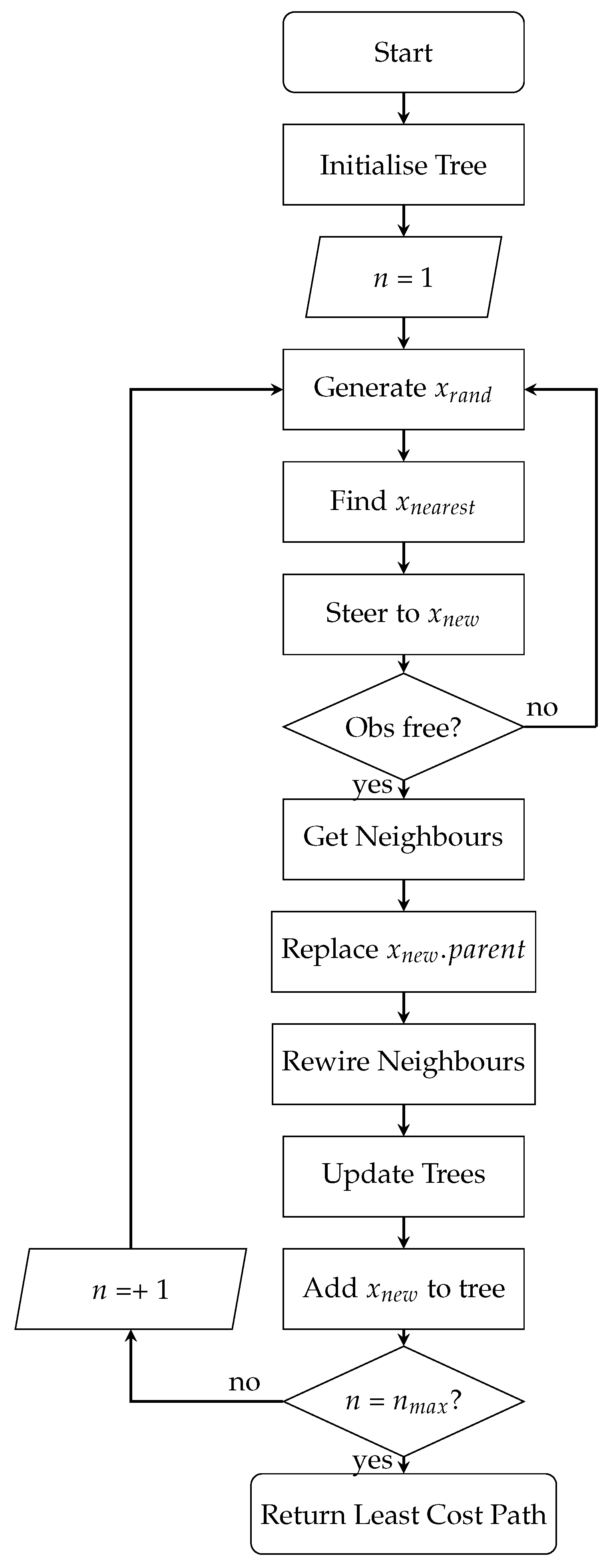
The first path planner considered within this study is a classical RRT algorithm [36]. As discussed above in Section 2.2, the RRT algorithm is a sampling-based path-planning method designed to efficiently explore high-dimensional spaces. This algorithm ensures rapid coverage of the search space but does not evaluate globally optimal paths. RRT incrementally builds a tree rooted at the start position by randomly sampling points in the configuration space and extending the nearest tree node toward each sampled point, subject to obstacle constraints. It is important to note that this algorithm traditionally considers the cost between nodes only in terms of distance. New nodes will be generated until the total number of nodes on the tree, n, is equal to the predefined maximum number of nodes, n m a x . The RRT algorithm searches the environment map following the process set out in Figure 2.
In the above process, new nodes are generated by first selecting a random point on the map, x r a n d . The nearest existing node on the tree is evaluated, x n e a r e s t , and the tree is steered towards x n e a r e s t to generate x n e w . If x n e w is in the obstacle free space (i.e., not impassible on the traversability map), then x n e w is added to the tree. This process continues until the maximum number of nodes is reached, and the lowest cost path is returned.

3.2. RRT*

Karaman and Frazzoli introduced RRT*, an asymptotically optimal extension of RRT, i.e., as the number of nodes on the tree increases, the cost of the returned solution converges on an optimal value [37]. The RRT* algorithm detailed here has two key differences compared to RRT. First, the nearest neighbours of x n e w are found, to evaluate if any would make a more appropriate parent node. Second, the neighbours are evaluated in order to rewire the tree for lower cost connections as new nodes are generated. Figure 3 details this process, as implemented for this work, where cost is measured in terms of path length.

3.3. Traversability-Based RRT*

Traversability-Based RRT* was introduced by Takemura and Ishigami, as an extension to the RRT* algorithm which ensures the generation of safe paths over rough 3D surfaces [15].
In this algorithm, the cost assigned to each node on the tree is no longer considered only in terms of distance. Four cost components are utilised: path length (R), roll ( ϕ ), pitch ( θ ), and required change in heading angle ( Δ ψ ) from the previous node to current node, x i . The ϕ and θ values are obtained by evaluating the kinematics of the rover at x i . Equation (1) shows the cost calculation for Traversability-Based RRT*.
c o s t ( x i ) = W R R i N R + W ϕ ϕ i N ϕ + W θ θ i N θ + W ψ Δ ψ i N ψ
In this formulation, W denotes the weighting coefficient assigned to each cost component, constrained such that their sum equals 1. N is introduced as a normalisation term to render the indices dimensionless, with its value determined by the maximum permissible threshold of each corresponding cost component (i.e., in a case where the maximum safe terrain slope angle is 15 ° , N ϕ = N θ = 15 ° ). A further restriction is placed on the generation of nodes to ensure that the tree’s exploration is biased towards the target point.

3.4. 3D-RRT*

The primary contribution of this work is the proposed variant of the Traversability-Based RRT* algorithm: 3D-RRT*. The objective of 3D-RRT* is to examine whether comparable results to Traversability-Based RRT* can be achieved without explicitly accounting for rover kinematics. This would not only generalise the algorithm but also reduce computational overhead. The proposed 3D-RRT* algorithm explicitly incorporates the terrain-aware metrics introduced in Section 1 (path flatness and path smoothness) through its cost function and tree expansion strategy. First, path flatness is addressed by integrating terrain slope into the cost function. Slope values are obtained from a traversability analysis, and nodes located on surfaces with lower inclination angles are assigned lower costs, biasing the planner toward flatter terrain. Second, path smoothness is promoted by constraining tree growth: when expanding the tree, the turning angle between a new node and its parent is limited, thereby reducing sharp changes in direction. A summary of this process is provided in Figure 4).
The proposed flowchart (Figure 4) incorporates three key modifications compared with the standard RRT* framework. First, an “Initialise Maps” block is added, which accounts for the need for prior knowledge of the mission site. Two map versions are initialised within the planner: a 3D environment map derived from Mars Reconnaissance Orbiter data, and a 2.5D traversability map, the evaluation of which is discussed later in this section. Second, the conventional “Obs Free?” check is replaced by a “Traversable?” block, where each new node is evaluated against predefined traversability criteria. A node is considered valid only if it is both reachable and does not exceed the maximum slope angle or turning limits relative to its parent node. Third, the “Evaluate Cost” step is extended beyond distance alone to include terrain slope and required turning, with the detailed definition of this cost function presented later in the section.
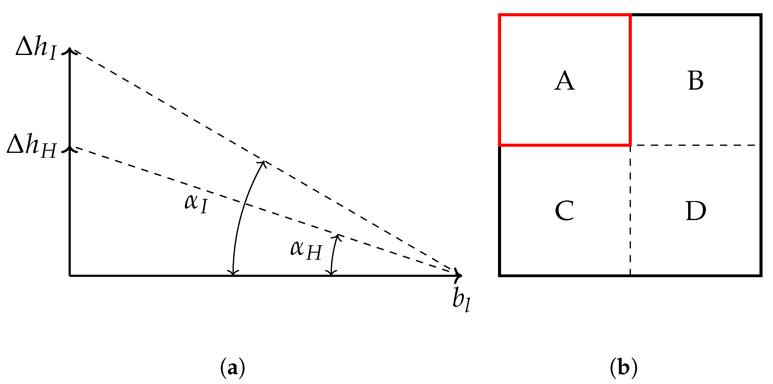
As previously highlighted, obtaining environmental data is a pre-requisite for this approach. In this study, high-resolution digital elevation maps (DEMs) from the Mars Reconnaissance Orbiter provide terrain information regarding the given mission site, from which slope angles are derived [49]. The terrain traversability analysis is performed for the given mission site to categorise regions as traversable, impassable, high risk, or unreachable. Traversable regions are deemed safe for exploration. Impassable terrain is defined by slope angles exceeding α I ± 15 ° , while high risk terrain corresponds to slope angles exceeding α H ± 10 ° . Terrain is classified as unreachable if it is isolated by surrounding impassable zones, assuming a nominal starting point at coordinate (0,0). Figure 5a shows the slope angle thresholds for high risk, α H , and impassable, α I , terrain categorisation, where b l the block length defined with in the map, in this case 0.25 m for a mission site composed of a 100 × 100 block grid. Δ h H is the altitude difference required between two neighbouring blocks for the current block to be categorised as high risk and Δ h I is the altitude difference required between two neighbouring blocks for the current block to be categorised as impassable. Figure 5b shows an example of comparison between neighbouring blocks. A is the first block to be checked, and it has three neighbours, B, C, and D. The value of Δ h between A and each of its neighbours is calculated. The worst case Δ h value is then used to categorise block A.
The 3D-RRT* algorithm incorporates three cost components when evaluating a node, x i : path length ( R i ), terrain slope angle ( α i ), and turning angle from the previous node ( Δ ψ i ). The slope angle α is obtained directly from the traversability analysis. The overall cost associated with node x i is defined as:
c o s t ( x i ) = W R R i N R + W α α i N α + W ψ Δ ψ i N ψ

4. Experimental Set-Up

4.1. Introduction

A simulation study has been conducted to enable a comparative evaluation of the four path-planning algorithms: RRT, RRT, Traversability-Based RRT*, and the proposed 3D-RRT*. While the 3D-RRT* algorithm is designed for general applicability with minimal prior environmental knowledge and limited platform-specific constraints, a micro-rover has been selected as the representative robotic platform for simulation and analysis. This platform has been mathematically modelled and implemented within MATLAB (2023a). The remainder of this section presents the micro-rover’s mathematical model, followed by a description of the guidance, navigation, and control (GNC) architecture, and concludes with the environmental modelling approach, including traversability analysis.

4.2. Mathematical Model of a 6-Wheel Rocker Bogie Micro Rover

To support the simulation study, a detailed mathematical model of the micro-rover has been developed. The micro-rover selected for this study has a small form factor, a rocker bogie suspension, and six fixed wheels (Figure 6). Differential drive steering is utilised.
The rover is described with respect to two coordinate frames: a Mars-fixed inertial frame and a body-fixed frame attached to the rover. Both frames are oriented according to the North-East-Down (NED) convention, where the positive Z-axis points downward from the centre of gravity [50], as illustrated in Figure 7.
The body-fixed translational velocity components are denoted by u, v, and w, and the rotational velocities by p, q, and r. The rover’s rigid body dynamics, with reference to the body-fixed frame and Mars-fixed frame, can be described by the matrix relationships shown in Equations (3)–(5) [50].
v ˙ η ˙ = A ( v ) B ( v ) J ( η ) 0 v η + M 1 0 τ
A ( v ) = ( C ( v ) + M 1 D ( v ) )
B ( v ) = M 1 g ( v )
The equations of motion, presented in Equation (6), are composed of several matrices and vectors. The body’s dynamics are described using a body-fixed velocity vector, v , and an inertially fixed position and orientation vector η . Matrices include the mass and inertia matrix, M , the Coriolis Matrix, C ( v ) , and the damping matrix, D ( v ) . The vector g ( v ) accounts for gravitational forces and moments, while the Euler matrix J ( η ) converts coordinates from the body-fixed to the Mars-fixed reference frame. Actuator-generated forces and moments are represented by the vector τ .
F X = m ( u ˙ + w . q v . r ) F Y = m ( v ˙ + u . r w . p ) F Z = m ( w ˙ + v . p u . q ) M K = J x . p ˙ + ( J z J y ) . q . r M M = J y . q ˙ + ( J x J z ) . p . r M N = J z . r ˙ + ( J y J x ) . p . q
The rover’s forces and moments are defined as follows: F X , F Y , and F Z for surge, sway, and yaw forces; and M K , M M , and M N for roll, pitch, and yaw moments. The vehicle’s mass is m, with its moments of inertia about the x, y, and z axes specified as J x , J y , and J z .

4.3. Guidance, Navigation, and Control

The micro-rover is equipped with a guidance, navigation, and control system, which allows it to traverse towards target waypoints within its environment. The guidance method is a line-of-sight (LOS) algorithm, which allows a rover to collect a set of waypoints, thus traversing a path [52] (Figure 8). An acceptance radius has been defined, R a c c , whereby a rover has collected a waypoint if the distance between its centre point and the target is less than R a c c . For this work R a c c = 0.25 m has been selected, i.e., one rover length.
The required change in heading angle, Δ ψ , to reach the waypoint, W P , is evaluated using Equation (7).
ψ W P = t a n 1 y W P y R x W P x R
The control system of the simulated micro-rover consists of one PID controller corresponding to its surge velocity, u, and one PID controller corresponding to its heading, ψ . As all wheels on the RBR rover are fixed and cannot rotate, skid steering is utilised. To cause the rover to turn, there must be a difference in the voltage supplied to the left hand side wheels of the rover (i.e., and the voltage supplied to the right hand side wheels of the rover).

4.4. Environment Model

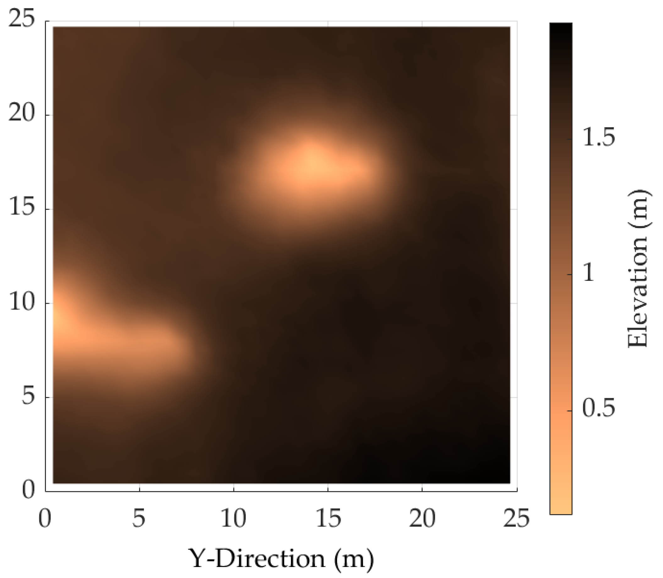
A mission site of 250 m × 250 m has been chosen in Jezero crater, Mars. Given that the rover’s scale is approximately 1 / 10 th that of the Perseverance rover, the mission site is proportionally reduced to a size of 25 m × 25 m. The environment model is generated using a digital terrain map [53] from the HiRISE orbiter [54]. Figure 9 shows this mission site as modelled in MATLAB.
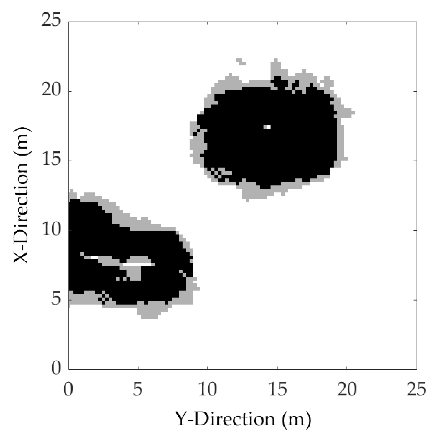
The mission site’s traversability is assessed using the method described in Section 3.4, as shown in Figure 10. This process sorted the terrain into four classifications: safe to explore (traversable), high-risk (slope of α H ± 10 ° ), and impassable (slope of α I ± 15 ° ), with the remaining areas being unreachable. These terrain thresholds are consistent with the Perseverance rover’s operational limits [24].
The Two Hill Pass Mission Site presents a suitable and challenging test environment, characterised by a high proportion of traversable terrain ( 77.31 % ), minimal unreachable areas ( 0.11 % ), and the presence of two prominent surface features. Additionally, 16.57 % of the terrain is classified as impassable, while 6.01 % is designated as high risk.

5. Results

Due to the stochastic nature of the sampling based path planners discussed above, two steps have been taken to ensure an equal comparison. First, at each stage in the investigation, 100 tests are run. This generates a data set that is representative of the overall performance of the planner. Second, each set of 100 tests has been given the same random seed within the MATLAB simulation.

5.1. Varying Maximum Nodes

It is important to establish the viable values of n m a x assigned to each tree, such that each planner is guaranteed to produce successful paths for the defined environment. Here, a successful path is defined as one where the final waypoint is within 1m of the target point (i.e., the maximum allowed step between nodes). Figure 11a shows the success rate of each RRT variation as the maximum number of nodes is increased, and Figure 11b provides a comparison of the planner time for each algorithm.
In Figure 11a, it can be seen that both RRT and RRT* perform relatively poorly at low values of n m a x . This is primarily because the trees initially explore the entire environment indiscriminately, which delays their progression towards the target point. Additionally, RRT and RRT* exhibit the same success rate. This is because the RRT* algorithm is exploring the full environment and is very unlikely to carry out rewiring so early on. As both algorithms are provided with the same random seed, these early paths are very similar. Both Traversability-Based RRT* and 3D-RRT* exhibit significantly higher success rates at low values of n m a x because the tree’s growth is biased towards the goal. All four planners exhibit 100% success rates at n m a x 1000 .
It is worth noting that RRT*, Traversability-Based RRT*, and 3D-RRT* experience increased performance in terms of path length, path smoothness, and path flatness as n m a x increases. However, the improvements observed are small. For example, Traversability-Based RRT* experienced a 14478 % increase in run time when moving from n m a x = 1000 to n m a x = 10,000, resulting in only a 0.843 % reduction in path length. For this reason, all further testing considers each planner at n m a x = 1000. At this value, each planner is guaranteed to provide a successful path, and return this path without incurring a large run time.

5.2. Characteristics of the RRT-Based Path-Planning Algorithms

Examples of the selected RRT-based algorithms, with 1000 nodes in each tree are shown in Figure 12. The start point is marked in green at position (2,2) and the target point is marked in red at position (23,23). RRT branches are shown in blue, rewired branches are shown in orange, and the final path is shown in purple.
The RRT and RRT* algorithms exhibit broad exploration of the environment during early stages of planning, with nodes distributed widely across the map and no inherent bias toward the goal location. RRT*, initiates local rewiring (visible in orange in the above figure) to minimise path cost, evaluated solely in terms of distance between nodes. In contrast, Traversability-Based RRT* and 3D-RRT* demonstrate a more directed search behaviour, with a higher density of nodes concentrated near the goal. This is a result of incorporating the mobility constraints of the robotic platform, which prioritise feasible and efficient paths within a reduced area. Both terrain-aware variants perform significant rewiring to reduce path cost, now influenced by terrain-specific cost metrics rather than distance alone. Despite the algorithmic simplification in 3D-RRT*, it produces search trees that are qualitatively similar to those generated by Traversability-Based RRT*.
While the path visually depicted in Figure 12d may appear to possess minor variations, it is important to acknowledge that the proposed 3D-RRT* algorithm is a stochastic planner. Consequently, its objective is to identify a feasible solution that balances the trade-off between path quality and computational efficiency, rather than to guarantee a globally optimal path. The resulting path represents the outcome of an optimisation process that considers a comprehensive cost function encompassing both path length and slope. Therefore, a visually smoother or shorter path does not necessarily correspond to a superior solution when evaluated against the full suite of metrics set out in Section 5.3.

5.3. Path Quality

In line with recent work by Mūnoz et al. [14], this study aims to provide a comparison of RRT based algorithms considering practical and meaningful path-planning metrics in the context of planetary-exploration missions. The following metrics are considered here:
  • Run Time ( C T ): This is the time taken by the path-planning algorithm to generate n m a x nodes and select a path.
  • Path Length ( C L ): To evaluate path length, the Euclidean distance between each sequential node on the path is summed.
  • Path Smoothness ( C ψ ): The path smoothness is defined as the total required turning angle accumulated over the path.
  • Path Flatness ( C α ): The flatness of the path is evaluated by taking the slope angle associated with each node from the traversability analysis and summing over the full path.
Overall path quality increases as the values of each of the above metrics decreases. Table 1 sets out the performance of each planner, providing the mean, μ , and standard deviation, σ , for each path quality metric.
For an initial comparison of path quality, the cost function weights for Traversability-Based RRT* have been set to W R = W ϕ = W θ = W ψ = 1 / 4 and the cost function weights for 3D-RRT* have been set to W R = W α = W ψ = 1 / 3 , to provide equal weighting to each cost component. The effect of varying these weights is explored further in Section 5.4. To reflect the nominal operational limits of the RBR rover used in this study, the normalisation factors of the Traversability-Based RRT* and 3D-RRT* algorithms were set as follows: N R = 1 m, N ψ = 60 ° , N ϕ = N θ = N α = 15 ° .
It can bee seen that, while RRT and RRT* evaluate paths more quickly, Traversability-Based RRT* and 3D-RRT* significantly outperform RRT and RRT* in terms of path length, path smoothness, and path flatness. Additionally, Traversability-Based RRT* and 3D-RRT* provide path quality of consistently better quality, with a lower standard deviation in each metric across the test sets. 3D-RRT* is able to provide paths of comparable quality to Traversability-Based RRT*, but at a significantly lower run time.

5.4. Varying Cost Weights

The effect of biasing the cost function weights in both Traversability-Based RRT* and 3D-RRT* in favour of a particular performance metric has been investigated. Table 2 sets out these variants. For both Traversability-Based RRT* and 3D-RRT*, variants have been evaluated which prioritise either path length (A and D), path smoothness (B and E), or path flatness (C and F).
Figure 13 shows the impact of varying the cost function weights on path quality over a set of 100 tests, where in each case the random seed is set with relation to the test index.
This initial research suggests that, while n m a x = 1000 is sufficient in providing successful paths, the random sampling of the RRT-based algorithm plays a larger role in the outcome of path quality than the weights applied to the cost function.

6. Discussion

The results of this study demonstrate the significant benefit of incorporating terrain-aware heuristics into RRT-based path-planning algorithms for planetary-exploration rovers. In particular, both Traversability-Based RRT* and the proposed 3D-RRT* achieved markedly better performance than classical RRT and RRT* across three of the four considered metrics: path length, smoothness, and flatness. For instance, as shown in Table 1, 3D-RRT* reduced mean path length by 13.5% compared to RRT ( p < 0.00001 ), while decreasing accumulated turning angle (path smoothness) by over 66% ( p < 0.00001 ). Both terrain-aware planners produced flatter routes, with mean slope angles more than 40% lower than those generated by classical RRT ( p < 0.00001 ). The directed search behaviour observed in Figure 12c,d reflects how terrain awareness and mobility constraints bias exploration towards feasible paths in the target region. A further strength of 3D-RRT* lies in its computational efficiency. Compared to Traversability-Based RRT*, 3D-RRT* reduced mean planning time from 14.078 to 6.437 s (a 54% improvement; p < 0.00001 ) while maintaining path length within 1% ( p < 0.203 ), path smoothness within 2% ( p < 0.448 ) and path flatness within 0.8% ( p < 0.439 ).
While this study demonstrates clear benefits, some limitations should be acknowledged. Due to the stochastic nature of sampling-based planning, some variability in results remains. Further, although cost function weighting influenced path characteristics (for example, prioritising path smoothness reduced accumulated turning by around 9%), random sampling effects remained the dominant source of variability. Path smoothness could be further enhanced using post-processing techniques such as Bézier curves or splines [55]. However, this study’s primary focus is on generating a path that respects practical terrain variations in the 3D simulated environment, and a comparative evaluation with post-processing methods is considered outside the scope of the current work. A comparative analysis with these post-processing techniques represents an interesting direction for future work.
The scope of this study does not include explicit evaluation of power consumption; however, energy efficiency remains a critical constraint for PERs. Power availability directly influences both locomotion and computational resources, and planners which minimise unnecessary travel or avoid steep inclines can indirectly reduce energy demand. Future work should therefore consider directly addressing power constraints within the planner cost function.
Building on these strengths and areas for improvement, another finding concerns multi-robot exploration. Since 3D-RRT* avoids explicit rover kinematics and uses only terrain slope in its cost function, it is inherently platform-agnostic. This generalisability enables its deployment across heterogeneous robot teams without significant reconfiguration of the planner. This aligns with emerging trends in planetary exploration, where multi-robot systems are increasingly being used to improve fault tolerance and extend mission capability.

7. Conclusions

This study has presented a comparative evaluation of four RRT-based path-planning algorithms (RRT, RRT*, Traversability-Based RRT*, and a newly proposed variant, 3D-RRT*) within a simulated 3D Martian environment. By incorporating the terrain-aware performance metrics of path length, path smoothness, flatness, and planning time, the evaluation reflects the practical requirements of planetary rover operations beyond classical distance-based optimisation. Key findings include:
  • Both terrain-aware planners (3D-RRT* and Traversability-Based RRT*) generated smoother, shorter, and flatter paths than classical RRT and RRT*.
  • 3D-RRT* achieved comparable path quality to Traversability-Based RRT* while halving computational time.
  • The 3D-RRT* algorithm’s simplicity and lack of platform-specific modelling make it well-suited to heterogeneous robot teams and dynamic mission environments.
Beyond improving individual rover paths, the computational efficiency of 3D-RRT* reduces strain on onboard processors, enabling more frequent replanning and more cautious terrain selection. This efficiency not only extends the operational lifespan of planetary rovers, but also increases the safety and reliability of their missions. By combining terrain awareness with low computational overhead, 3D-RRT* enhances the autonomy and resilience of planetary exploration, supporting safer and more efficient paths in challenging environments.
Some aspects warrant further investigation to fully establish the method’s robustness. The present evaluation is restricted to a single simulated terrain model, which may not capture the full diversity of planetary conditions such as highly deformable soils or extremely rocky landscapes. Moreover, validation has been confined to simulation, and real-world performance may be influenced by factors such as sensor noise, and computational constraints on physical rovers. Future work will therefore focus on broadening the set of tested terrain scenarios to better represent the variability of planetary environments, as well as implementing 3D-RRT* on hardware platforms for field experiments. These steps will enable a more comprehensive assessment of the algorithm’s robustness.
Despite these constraints, the results demonstrate that 3D-RRT* provides a practical balance between terrain awareness and computational efficiency for PER path planning. Although developed in the context of Mars exploration, the underlying principles are broadly applicable to other challenging or remote environments, including autonomous robotic operations in search and rescue scenarios.

Author Contributions

Conceptualisation, S.S. and E.M.; methodology, S.S.; software, S.S.; formal analysis, S.S.; investigation, S.S.; data curation, S.S.; writing—original draft preparation, S.S.; writing—review and editing, S.S., E.M. and D.T.; visualisation, S.S.; supervision, E.M. and D.T. All authors have read and agreed to the published version of the manuscript.

Funding

This research was funded by the Engineering and Physical Science Research Council.

Institutional Review Board Statement

Not applicable.

Informed Consent Statement

Not applicable.

Data Availability Statement

Data will be made available on request.

Conflicts of Interest

The authors declare no conflicts of interest.

References

  1. Ocampo, A.; Friedman, L.; Logsdon, J. Why space science and exploration benefit everyone. Space Policy 1998, 14, 137–143. [Google Scholar] [CrossRef]
  2. Sutton, J.P. Clinical benefits of bioastronautics. In Handbook of Bioastronautics; Springer International Publishing: Cham, Switzerland, 2021; pp. 7–19. [Google Scholar]
  3. Vernikos, J. Human exploration of space: Why, where, what for? Hippokratia 2008, 12 (Suppl. S1), 6. [Google Scholar]
  4. White, R.J.; Averner, M. Humans in space. Nature 2001, 409, 1115–1158. [Google Scholar] [CrossRef]
  5. Muirhead, B.K. Mars rovers, past and future. In Proceedings of the 2004 IEEE Aerospace Conference Proceedings (IEEE Cat. No. 04TH8720), Big Sky, MT, USA, 6–13 March 2004; IEEE: Piscataway, NJ, USA, 2004; Volume 1. [Google Scholar]
  6. Moeller, R.C.; Jandura, L.; Rosette, K.; Robinson, M.; Samuels, J.; Silverman, M.; Brown, K.; Duffy, E.; Yazzie, A.; Jens, E.; et al. The Sampling and Caching Subsystem (SCS) for the scientific exploration of Jezero crater by the Mars 2020 Perseverance rover. Space Sci. Rev. 2021, 217, 5. [Google Scholar] [CrossRef]
  7. Farley, K.A.; Williford, K.H.; Stack, K.M.; Bhartia, R.; Chen, A.; de la Torre, M.; Hand, K.; Goreva, Y.; Herd, C.D.; Hueso, R.; et al. Mars 2020 mission overview. Space Sci. Rev. 2020, 216, 142. [Google Scholar] [CrossRef]
  8. Koktas, E.; Başar, E. Communications for the planet mars: Past, present, and future. IEEE Aerosp. Electron. Syst. Mag. 2024, 39, 216–258. [Google Scholar] [CrossRef]
  9. Miao, Q.; Wei, G. A Comprehensive Review of Path-Planning Algorithms for Planetary Rover Exploration. Remote Sens. 2025, 17, 1924. [Google Scholar] [CrossRef]
  10. Swinton, S.; McGookin, E. Fault Diagnosis for a Team of Planetary Rovers. In Proceedings of the 2022 UKACC 13th International Conference on Control (CONTROL), Plymouth, UK, 20 April 2022; IEEE: Piscataway, NJ, USA, 2022; pp. 94–99. [Google Scholar]
  11. Dearden, R.; Willeke, T.; Simmons, R.; Verma, V.; Hutter, F.; Thrun, S. Real-time fault detection and situational awareness for rovers: Report on the mars technology program task. In Proceedings of the 2004 IEEE Aerospace Conference Proceedings (IEEE Cat. No. 04TH8720), Big Sky, MT, USA, 6–13 March 2004; IEEE: Piscataway, NJ, USA, 2004; Volume 2, pp. 826–840. [Google Scholar]
  12. Ricano, J.R.; Yuasa, S.; Hino, R.; Koshi, T.; Oyama, T.; Nagaoka, K. Resilient mobility of a four-wheeled planetary rover with active suspension. Acta Astronaut. 2025, 229, 418–429. [Google Scholar] [CrossRef]
  13. Swinton, S.; Ewers, J.H.; McGookin, E.; Anderson, D.; Thomson, D. Autonomous mission planning for planetary surface exploration using a team of micro rovers. Front. Robot. AI 2025, 12, 1565173. [Google Scholar] [CrossRef]
  14. Muñoz, P.; Bellutta, P.; R-Moreno, M.D. Proposing new path-planning metrics for operating rovers on Mars. Sci. Rep. 2023, 13, 22256. [Google Scholar] [CrossRef]
  15. Takemura, R.; Ishigami, G. Traversability-Based RRT* for planetary rover path planning in rough terrain with LIDAR point cloud data. J. Robot. Mechatronics 2017, 29, 838–846. [Google Scholar] [CrossRef]
  16. Ishigami, G.; Nagatani, K.; Yoshida, K. Path following control with slip compensation on loose soil for exploration rover. In Proceedings of the 2006 IEEE/RSJ International Conference on Intelligent Robots and Systems, Beijing, China, 9–15 October 2006; IEEE: Piscataway, NJ, USA, 2006; pp. 5552–5557. [Google Scholar]
  17. Ishigami, G.; Nagatani, K.; Yoshida, K. Path planning for planetary exploration rovers and its evaluation based on wheel slip dynamics. In Proceedings of the 2007 IEEE International Conference on Robotics and Automation, Roma, Italy, 10 April 2007; IEEE: Piscataway, NJ, USA, 2007; pp. 2361–2366. [Google Scholar]
  18. Sock, J.; Kim, J.; Min, J.; Kwak, K. Probabilistic traversability map generation using 3D-LIDAR and camera. In Proceedings of the 2016 IEEE International Conference on Robotics and Automation (ICRA), Stockholm, Sweden, 16 May 2016; IEEE: Piscataway, NJ, USA, 2016; pp. 5631–5637. [Google Scholar]
  19. Dergachev, S.; Muravyev, K.; Yakovlev, K. 2.5 d mapping, pathfinding and path following for navigation of a differential drive robot in uneven terrain. IFAC-PapersOnLine 2022, 55, 80–85. [Google Scholar] [CrossRef]
  20. Vayugundla, M.; Kuhne, M.; Wedler, A.; Triebel, R. Datasets and Benchmarking of a path planning pipeline for planetary rovers. In Proceedings of the 2022 IEEE/RSJ International Conference on Intelligent Robots and Systems (IROS) Workshop: Evaluating Motion Planning Performance, Kyoto, Japan, 23 October 2022. [Google Scholar]
  21. Ono, M.; Fuchs, T.J.; Steffy, A.; Maimone, M.; Yen, J. Risk-aware planetary rover operation: Autonomous terrain classification and path planning. In Proceedings of the 2015 IEEE Aerospace Conference, Big Sky, MT, USA, 7 March 2015; IEEE: Piscataway, NJ, USA, 2015; pp. 1–10. [Google Scholar]
  22. Flessa, T.; McGookin, E.W.; Thomson, D.G. Taxonomy, systems review and performance metrics of planetary exploration rovers. In Proceedings of the 2014 13th International Conference on Control Automation Robotics & Vision (ICARCV), Singapore, 10–12 December 2014; IEEE: Piscataway, NJ, USA, 2014; pp. 1554–1559. [Google Scholar]
  23. Harrington, B.D.; Voorhees, C. The challenges of designing the rocker-bogie suspension for the mars exploration rover. In Proceedings of the 37th Aerospace Mechanisms Symposium, Galveston, TX, USA, 19–21 May 2004. [Google Scholar]
  24. Rankin, A.; Maimone, M.; Biesiadecki, J.; Patel, N.; Levine, D.; Toupet, O. Driving curiosity: Mars rover mobility trends during the first seven years. In Proceedings of the 2020 IEEE Aerospace Conference, Big Sky, MT, USA, 7–14 March 2020; IEEE: Piscataway, NJ, USA, 2020; pp. 1–19. [Google Scholar]
  25. Yen, J. Slip Validation and Prediction for Mars Exploration Rovers. Sens. Transducers 2008, 90, 233–242. [Google Scholar]
  26. Bajracharya, M.; Maimone, M.W.; Helmick, D. Autonomy for mars rovers: Past, present, and future. Computer 2008, 41, 44–50. [Google Scholar] [CrossRef]
  27. Carsten, J.; Rankin, A.; Ferguson, D.; Stentz, A. Global path planning on board the mars exploration rovers. In Proceedings of the 2007 IEEE Aerospace Conference, Big Sky, MT, USA, 3–10 March 2007; IEEE: Piscataway, NJ, USA, 2007; pp. 1–11. [Google Scholar]
  28. Ferguson, D.; Stentz, A. Using interpolation to improve path planning: The Field D* algorithm. J. Field Robot. 2006, 23, 79–101. [Google Scholar] [CrossRef]
  29. Carsten, J.; Rankin, A.; Ferguson, D.; Stentz, A. Global planning on the mars exploration rovers: Software integration and surface testing. J. Field Robot. 2009, 26, 337–357. [Google Scholar] [CrossRef]
  30. Verma, V.; Maimone, M.W.; Gaines, D.M.; Francis, R.; Estlin, T.A.; Kuhn, S.R.; Rabideau, G.R.; Chien, S.A.; McHenry, M.M.; Graser, E.J.; et al. Autonomous robotics is driving Perseverance rover’s progress on Mars. Sci. Robot. 2023, 8, eadi3099. [Google Scholar] [CrossRef] [PubMed]
  31. Verma, V.; Hartman, F.; Rankin, A.; Maimone, M.; Del Sesto, T.; Toupet, O.; Graser, E.; Myint, S.; Davis, K.; Klein, D.; et al. First 210 solar days of Mars 2020 Perseverance robotic operations-mobility, robotic arm, sampling, and helicopter. In Proceedings of the 2022 IEEE Aerospace Conference (AERO), Big Sky, MT, USA, 5–12 March 2022; IEEE: Piscataway, NJ, USA, 2022; pp. 1–20. [Google Scholar]
  32. Sakayori, G.; Ishigami, G. Energy-aware trajectory planning for planetary rovers. Adv. Robot. 2021, 35, 1302–1316. [Google Scholar] [CrossRef]
  33. Lamarre, O.; Limoyo, O.; Marić, F.; Kelly, J. The Canadian planetary emulation terrain energy-aware rover navigation dataset. Int. J. Robot. Res. 2020, 39, 641–650. [Google Scholar] [CrossRef]
  34. Plonski, P.A.; Tokekar, P.; Isler, V. Energy-efficient path planning for solar-powered mobile robots. J. Field Robot. 2013, 30, 583–601. [Google Scholar] [CrossRef]
  35. Fallah, S.; Yue, B.; Vahid-Araghi, O.; Khajepour, A. Energy management of planetary rovers using a fast feature-based path planning and hardware-in-the-loop experiments. IEEE Trans. Veh. Technol. 2013, 62, 2389–2401. [Google Scholar] [CrossRef]
  36. LaValle, S. Rapidly-Exploring Random Trees: A New Tool for Path Planning; Research Report. TR 98-11; Iowa State University: Ames, IA, USA, 1998. [Google Scholar]
  37. Karaman, S.; Frazzoli, E. Sampling-based algorithms for optimal motion planning. Int. J. Robot. Res. 2011, 30, 846–894. [Google Scholar] [CrossRef]
  38. Urmson, C.; Simmons, R. Approaches for heuristically biasing RRT growth. In Proceedings of the 2003 IEEE/RSJ International Conference on Intelligent Robots and Systems (IROS 2003) (Cat. No. 03CH37453), Las Vegas, NV, USA, 27 October–1 November 2003; IEEE: Piscataway, NJ, USA, 2003; Volume 2, pp. 1178–1183. [Google Scholar]
  39. Ettlin, A.; Bleuler, H. Rough-terrain robot motion planning based on obstacleness. In Proceedings of the 2006 9th International Conference on Control, Automation, Robotics and Vision, Singapore, 5–8 December 2006; IEEE: Piscataway, NJ, USA, 2006; pp. 1–6. [Google Scholar]
  40. Wang, Y.; Yuan, Q.; Guo, Y.; Han, W. Path planning for lunar rover based on Bi-RRT algorithm. In Proceedings of the 2021 40th Chinese Control Conference (CCC), Shanghai, China, 26 July 2021; IEEE: Piscataway, NJ, USA, 2021; pp. 4211–4216. [Google Scholar]
  41. Swinton, S.; McGookin, E. A Novel, RRT* Based Approach to the Coordination of Multiple Planetary Rovers. In Proceedings of the 2022 UKACC 13th International Conference on Control (CONTROL), Plymouth, UK, 20 April 2022; IEEE: Piscataway, NJ, USA, 2022; pp. 88–93. [Google Scholar]
  42. Hidalgo-Paniagua, A.; Bandera, J.P.; Ruiz-de-Quintanilla, M.; Bandera, A. Quad-RRT: A real-time GPU-based global path planner in large-scale real environments. Expert Syst. Appl. 2018, 99, 141–154. [Google Scholar] [CrossRef]
  43. Wang, J.; Chi, W.; Li, C.; Wang, C.; Meng, M.Q. Neural RRT*: Learning-based optimal path planning. IEEE Trans. Autom. Sci. Eng. 2020, 17, 1748–1758. [Google Scholar] [CrossRef]
  44. Liao, B.; Wan, F.; Hua, Y.; Ma, R.; Zhu, S.; Qing, X. F-RRT*: An improved path planning algorithm with improved initial solution and convergence rate. Expert Syst. Appl. 2021, 184, 115457. [Google Scholar] [CrossRef]
  45. Yu, J.; Chen, C.; Arab, A.; Yi, J.; Pei, X.; Guo, X. RDT-RRT: Real-time double-tree rapidly-exploring random tree path planning for autonomous vehicles. Expert Syst. Appl. 2024, 240, 122510. [Google Scholar] [CrossRef]
  46. Lanfeng, Z.; Lina, Y.; Hua, F. Lunar Rover Path Planning Based on Comprehensive Genetic Algorithm Based on Slip Prediction. J. Phys. Conf. Ser. 2019, 1267, 012097. [Google Scholar] [CrossRef]
  47. Zhang, J.; Xia, Y.; Shen, G. A novel learning-based global path planning algorithm for planetary rovers. Neurocomputing 2019, 361, 69–76. [Google Scholar] [CrossRef]
  48. Yu, X.; Wang, P.; Zhang, Z. Learning-based end-to-end path planning for lunar rovers with safety constraints. Sensors 2021, 21, 796. [Google Scholar] [CrossRef] [PubMed]
  49. McEwen, A.S.; Eliason, E.M.; Bergstrom, J.W.; Bridges, N.T.; Hansen, C.J.; Delamere, W.A.; Grant, J.A.; Gulick, V.C.; Herkenhoff, K.E.; Keszthelyi, L.; et al. Mars reconnaissance orbiter’s high resolution imaging science experiment (HiRISE). J. Geophys. Res. Planets 2007, 112, E05S02. [Google Scholar] [CrossRef]
  50. Fossen, T.I. Handbook of Marine Craft Hydrodynamics and Motion Control; John Wiley & Sons: Hoboken, NJ, USA, 2011. [Google Scholar]
  51. Swinton, S.; McGookin, E.; Thomson, D. Design of a Health Monitoring System for a Planetary Exploration Rover. In Proceedings of the 2024 International Conference on Space Robotics (iSpaRo), Luxembourg, 24 June 2024; IEEE: Piscataway, NJ, USA, 2024; pp. 218–223. [Google Scholar]
  52. Breivik, M. Nonlinear Maneuvering Control of Underactuated Ships. Master’s Thesis, Norwegian University of Science and Technology, Trondheim, Norway, 2003. [Google Scholar]
  53. HiRISE. University of Arizona [Internet]. Candidate Landing Site for 2020 Mission in Jezero Crater. Available online: https://www.uahirise.org/dtm/dtm.php?ID=ESP_045994_1985 (accessed on 11 August 2022).
  54. Bergstrom, J.W.; Delamere, W.A.; McEwen, A. MRO High Resolution Imaging Science Experiment (HiRISE): Instrument Test, Calibration and Operating Constraints. In Proceedings of the 55th International Astronautical Congress of the International Astronautical Federation, the International Academy of Astronautics, and the International Institute of Space Law 2004, Vancouver, BC, Canada, 4–8 October 2004; p. Q-3. [Google Scholar]
  55. Türkkol, B.Z.; Altuntaş, N.; Çekirdek Yavuz, S. A Smooth Global Path Planning Method for Unmanned Surface Vehicles Using a Novel Combination of Rapidly Exploring Random Tree and Bézier Curves. Sensors 2024, 24, 8145. [Google Scholar] [CrossRef] [PubMed]
Figure 1. NASA’s Perseverance rover in July 2024. The rover can be seen in an environment of uneven, rocky terrain (Credit: NASA/JPL-Caltech/MSSS).
Robotics 14 00135 g001
Figure 2. RRT algorithm flowchart.
Robotics 14 00135 g002
Figure 3. RRT* algorithm flowchart.
Robotics 14 00135 g003
Figure 4. 3D-RRT* algorithm flowchart.
Robotics 14 00135 g004
Figure 5. Traversability analysis comparing the altitude of neighbouring blocks. (a) Threshold angles for high risk and impassable terrain regions. (b) An example of neighbour altitude checking. A is the current block being evaluated.
Robotics 14 00135 g005
Figure 6. The 6-wheel micro-rover utilised in this work [13].
Robotics 14 00135 g006
Figure 7. Coordinate frames used in the RBR rover model: Mars-fixed axes ((XM, YM, ZM in (blue)) and rover body-fixed axes (XB, YB, ZB in (red)) [51].
Robotics 14 00135 g007
Figure 8. Evaluation of required change in heading angle, Δ ψ , within line-of-sight guidance algorithm.
Robotics 14 00135 g008
Figure 9. Mission site surface map.
Robotics 14 00135 g009
Figure 10. Mission site traversability map where traversable regions are shown in white, impassable regions are shown in black, high risk regions are shown in grey.
Robotics 14 00135 g010
Figure 11. Performance across path-planning algorithms as n m a x increases. (a) Effect of increasing n m a x on success rate; (b) Effect of increasing n m a x on planner time.
Robotics 14 00135 g011
Figure 12. Representative examples of the selected RRT-based algorithms, with n m a x = 1000. (a) RRT; (b) RRT*; (c) Traversability-Based RRT*; (d) 3D-RRT*.
Robotics 14 00135 g012
Figure 13. The effect of varying cost equation weighting components on path quality, compared to assigning equal weighting.
Robotics 14 00135 g013
Table 1. A comparison of RRT-based path-planning algorithms with n m a x = 1000, over 100 tests.
C T ( s ) C L ( m ) C ψ ( rad ) C α ( rad )
Planner Type μ σ μ σ μ σ μ σ
RRT0.3780.00640.9752.99429.0554.2912.0000.141
RRT*1.1610.00740.1562.55527.8184.1731.9480.121
Traversability-Based RRT*14.0780.44935.1141.6149.9031.75881.1420.083
3D-RRT*6.4370.14435.4571.8599.7071.8641.1330.080
Table 2. Weights assigned to each variant of traversability-based RRT* and 3D-RRT*.
IDPath Planner W R W ϕ W θ W ψ W α
ATraversability-Based RRT*0.70.10.10.1N/A
BTraversability-Based RRT*0.10.10.10.7N/A
CTraversability-Based RRT*0.10.40.40.1N/A
D3D-RRT*0.8N/AN/A0.10.1
E3D-RRT*0.1N/AN/A0.80.1
F3D-RRT*0.1N/AN/A0.10.8
Disclaimer/Publisher’s Note: The statements, opinions and data contained in all publications are solely those of the individual author(s) and contributor(s) and not of MDPI and/or the editor(s). MDPI and/or the editor(s) disclaim responsibility for any injury to people or property resulting from any ideas, methods, instructions or products referred to in the content.