Abstract
The appearance of construction defects in buildings can arise from a variety of factors, ranging from issues during the design and construction phases to problems that develop over time with the lifecycle of a building. These defects require repairs, often in the context of a significant shortage of skilled labor. In addition, such work is often physically demanding and carried out in hazardous environments. Consequently, adopting autonomous robotic systems in the construction industry becomes essential, as they can relieve labor shortages, promote safety, and enhance the quality and efficiency of repair and maintenance tasks. Hereupon, the present study introduces an end-to-end framework towards the automation of shotcreting tasks in cases where construction or repair actions are required. The proposed system can scan a construction scene using a stereo-vision camera mounted on a robotic platform, identify regions of defects, and reconstruct a 3D model of these areas. Furthermore, it automatically calculates the required 3D volumes to be constructed to treat a detected defect. To achieve all of the above-mentioned technological tools, the developed software framework employs semantic segmentation and 3D reconstruction modules based on YOLOv8m-seg, SiamMask, InfiniTAM, and RTAB-Map, respectively. In addition, the segmented 3D regions are processed by the volumetric modeling component, which determines the amount of concrete needed to fill the defects. It generates the exact 3D model that can repair the investigated defect. Finally, the precision and effectiveness of the proposed pipeline are evaluated in actual construction site scenarios, featuring reinforcement bars as defective areas.
1. Introduction
In the construction sector, many aspects dynamically develop and change over time during construction or repair activities. Following this, various factors, such as inadequate maintenance, utilization of inferior materials, and aging of materials, could potentially lead to the appearance of construction defects during the lifespan of several elements within buildings [1]. Despite the advancements in building technology, there seems to be no decrease in the occurrence of defects; hence, maintaining building operations affected by defects remains a challenging task. The main objective of defect maintenance is to sustain the optimal performance of a building throughout its intended lifetime as much as possible. Typically, when a construction defect is identified, engineers or maintenance personnel evaluate its specific magnitude, develop an appropriate solution, and finally, create a maintenance plan. In general, the evaluation process for a defect is often unpredictable and may uncover additional defects during scheduled maintenance, thereby reducing work efficiency and increasing maintenance costs. Additionally, inadequate or improper maintenance solutions could even diminish the condition of repairing a structure. Consequently, the challenges associated with maintaining building operations in the field of construction defects underscore the demand for innovative solutions, aiming to enhance the precision and efficacy of defect identification building maintenance management and restoration. Such an innovative initiative is the application of three-dimensional (3D) reconstruction.
In particular, the concept of three-dimensional (3D) reconstruction in robotics involves the creation of 3D representations of the surroundings from sensor data. Typically, these 3D representations entail point cloud models, mesh models, and geometric models, with point cloud models serving as the basis [2]. Due to their efficiency and cost-effectiveness, 3D reconstruction techniques have been widely applied in various fields, such as medical engineering, surveying engineering, and civil engineering [3]. Specifically, their applications in the field of civil engineering have been pivotal in the preservation of historical buildings, analyzing the energy efficiency of buildings, and capturing pavement surface textures [4]. Through the aid of robotic and machine vision systems, which gain ever-increasing ground as effective tools in the construction sector, the 3D reconstruction process can be enabled for the generation of 3D digital representations of elements within construction sites. These operations list the intricate development of building and construction information models (BIM/CIM) [2], which digitally replicate physical assets on a synthesized 3D model of the construction site, accompanied by additional modeling of their ongoing operations. This allows for progress tracking and monitoring of an asset throughout its existence, from initial design to construction, operations, and maintenance. In terms of progress tracking and production monitoring, BIM models can assist in the comparison of the actual (“as-built”) state of the project with the “as-designed” state defined in the contractual agreement [5]. In addition to BIM models, 3D reconstruction is also adapted for the development of mechanical, electrical, and plumbing (MEP) systems [6], either as standalone models or integrated into BIMs [7]. Hence, the application of 3D reconstruction in the construction sector proves beneficial, empowering workers with valuable insights and prior knowledge through the development of detailed 3D models. Consequently, it improves decision-making for optimal resource allocation and material usage, resulting in enhanced operational efficiency and well-designed strategies.
The need for automation in civil infrastructure is even more evident in the field of construction with shotcrete, which is the most commonly used technique for surface rehabilitation and tunnel construction [8]. Shotcrete involves the pneumatic application of mortar or concrete onto a surface and requires a labor-intensive manual process where the nozzle operator empirically controls the amount of sprayed concrete, as depicted in Figure 1.

Figure 1.
In (a,c), the construction of tunnels is depicted, while (b) shows the construction of ground support walls. All images feature exposed reinforcement bars and highlight the labor-intensive process of spraying concrete (shotcreting) to fill the surface [9].
Currently, the amount of concrete sprayed highly depends on the nozzle operator’s expertise [9], resulting in considerable material wastage, as well as exposing workers to serious health risks due to the concrete rebound effect. Alternatively, 3D surface reconstruction could be deployed as a precise gauging method to estimate the thickness level of the area requiring concrete coverage, especially in the use case of ground support walls within shotcreting applications. Notably, semantic understanding is a key component for identifying regions of interest (ROI) to limit the reconstruction process to relevant areas. In addition, a semantic understanding of the environment of a robotic system is imperative for navigation purposes, such as to approach a region of interest in preparation for manipulation. However, there is limited exploration into integrating geometric data models generated through 3D scanning techniques and artificial intelligence (AI) approaches for restoring the geometrical characteristics of a defective structure [10].
Therefore, the objective of the present study is to introduce a cutting-edge methodology capable of inspecting a construction site, identifying defects, reconstructing the examined scene, and implementing a repair procedure to ensure the smooth operation as well as the structural integrity of the investigated building. We propose a software framework for autonomous volumetric modeling, which relies on a semantic 3D reconstruction module that identifies regions of interest (ROI), creates a 3D model of this region, and calculates the volume that needs to be filled to fix defects or build a structure from scratch.
2. Related Work
2.1. Three-Dimensional Reconstruction
The techniques commonly deployed in the field of 3D reconstruction can generally be categorized as offline and online approaches [11]. Online dense 3D reconstruction systems utilize visual odometry (VO) to track the pose of the current camera frame and fuse data into a dense map [12]. Instead, offline systems use pre-computed RGB-D odometry via structure from motion (SfM) techniques [13] to predict the pose between subsequent frames [11]. Such systems encompass recent advancements in 3D rendering techniques in neural radiance fields (NeRF) [14] and, more recently, 3D Gaussian splatting (3DGS) [15]. NeRF-based techniques rely on a regression method for opacity and color, alongside numerical integration, aiming to estimate the real step of the volumetric rendering function using images with known camera poses. By leveraging images with known camera poses, NeRF-based techniques utilize a regression method for opacity and color, alongside numerical integration, aiming to estimate the real step of a volumetric rendering function. Similar to NeRF, 3DGS uses a point cloud as computed by an SfM technique [13] and then converts each point into overlapping Gaussian splats with color and position. Next, a training process using gradient descent is deployed to predict Gaussian particles representing covariance and transparency, along with color and position. In contrast to NeRF, 3DGS performs differentiable rasterization. Although NeRF variants such as Instant-NGP [16] managed to drastically drop the required training/testing time, using a multi-resolution hash encoding and a lightweight MLP, 3DGS is significantly closer to real-time performance, as NeRF per-pixel ray marching remains a crucial bottleneck for rendering speed [17].
Some noteworthy robotic applications of NeRF-based techniques in the construction sector entail Inspection-NeRF [18], which is a method applied to capture surface defects by a wall-climbing robot to synthesize a 3D model of the scene. In [19], the 3D scene is depicted by [16], paired with a semantic segmentation module, aiming to construct detailed BIM models. To the best of our knowledge, there are no 3DGS-based works specifically adapted for robotics and construction applications. Nevertheless, there are certain offline SLAM 3DGS-based methods that offer dense mapping representations, such as [17,20,21].
Therefore, the main drawback among the aforementioned techniques lies in their optimization for offline usage, impeding their integration into a real-time, robotic-oriented reconstruction pipeline [22]. Simultaneously, their performance is heavily reliant on high-end GPUs to fully harness and leverage the latest performance enhancements of modern graphic cards. To partially mitigate this challenge and also tackle the barriers imposed by absolute scale recovery and long computational requirements, as reviewed in [23], several offline-based systems integrate existing visual-SLAM odometry modules. In [22], live RGB-D data streams are fused to calculate camera pose estimation using a Snake-SLAM algorithm, while input streams are processed by an encoder–decoder network to output the features as a photo-realistic image. On the contrary, both Orbeez-SLAM [24] and vMAP [25] deploy ORB-SLAM2 for the computation of visual odometry. However, the first leverages Instant-NGP for formulating an implicit neural representation, whereas the second proposes the usage of small MLPs corresponding to each of the detected objects. In the works of [12,26], Gaussian splatting was combined with camera position tracking through ORB-SLAM3 and Generalized-ICP, respectively.
Typical approaches such as TSDF-based techniques are still widely deployed as the fundamental methods in online dense 3D reconstruction. KinectFusion [27] was the first algorithm to deploy real-time volumetric truncated signed distance fields (TSDF). KinectFusion played a pivotal role in the later advancements of the GPU-accelerated TSDF family of algorithms for scene reconstruction using depth images, leading to works by [28,29]. In particular, InfiniTAM uses RGB-D images as input to estimate camera poses and outputs a globally consistent TSDF or surfel-based reconstruction. On top of other similar works, it is capable of handling large-scale scenes, while it can handle tracking failures featuring a keyframe-based relocalization system. However, the common challenge of these works is their susceptibility to pose drift, often resulting in the corruption of the entire reconstructed scene [11]. Additionally, [30] utilized RGB-D and stereo input data to compute real-time TSDFs from Euclidean signed distance fields (ESDF) to build implicit surfaces. Similarly, in [31], a large real-time metric-semantic SLAM framework for robotic applications is presented, which partially encapsulates the work of [30] for 3D reconstruction, optionally paired with semantic labeling in 3D.
In our work, we applied a purely online dense reconstruction method based on TSDF [29] to capitalize on a lightweight GPU-accelerated method for robotic application. It seamlessly handles large-scale scenes, which is crucial to fulfil our objectives for construction scenes. Following the notion of integrating SLAM odometry components into 3D rendering techniques, we combine the visual odometry estimation of RTAB-Map into InfiniTAM’s pipeline for improved accuracy.
2.2. Semantic Segmentation
To establish an understanding of the environment surrounding a robot, it is imperative to establish the locations of objects and their type. This task can either be done sparsely through bounding box detection or densely through semantic segmentation. A dense semantic map of an image is useful for applications requiring a higher level of granularity and precision.
Nowadays, segmentation models are mainly deep-learning-based. While models like U-Net [32], DeepLabV3 [33], PSPNet [34], and HRNet [35] use CNN-based backbones, a general trend of adapting Transformer-based backbones can be observed. More recent transformer-based models are SegFormer, using a Mix Transformer (MiT) [36], SETR, using a Vision Transformer (ViT) [37], and MaskFormer, using a Shifted Window (Swin) Transformer or a classical ResNet backbone [38].
While not strictly being semantic segmentation models, Mask R-CNN [39] and YOLOv8 [40] perform instance segmentation, i.e., they first make sparse prediction with bounding boxes and then generate dense masks within those boxes. However, one can use these to assemble an image-level semantic mask.
In concrete construction and maintenance, these models are used to detect exposed reinforcement bars on concrete structures, as they indicate defects in need of repair. In Ref. [41], a classification algorithm is used to detect the presence of various concrete defects such as spalling, cracks, efflorescences, and scalings. All these defects can also occur in the presence of exposed reinforcement bars. Ref. [42] extends this work using similar classes but proposing a bounding box detector for defect detection, moving from image-level classification to sparse detection. Ref. [43] focuses on exposed rebar detection, using an AlexNet-based classifier for image patches, thus achieving coarse-level dense prediction. Ref. [44] presents a synthetic dataset depicting rebars and trains a Mask-RCNN model to perform instance segmentation of these. This dense prediction model can aid in the quality control of rebar lattices and makes autonomous rebar tying possible since a robot would need to know the location of rebars in its environment.
While the previously mentioned works focus mainly on defect detection and quality control, our work focuses on building new structures where reinforcement bars need to be filled with concrete. For this, we train the YOLOv8 dense prediction model and pair it with the SiamMask mask tracking model [45] to stabilize the output of the YOLOv8 model.
2.3. Defect Detection and 3D Modeling
Over the past few decades, there have been significant advancements in shotcrete applications [46]. This procedure entails the careful blending of concrete components, including aggregates, water, and binders, followed by their conveyance to a spraying nozzle. Nevertheless, traditional manual concrete spraying operations present challenges such as considerable construction dust and rebound, which can endanger the health of the workforce [47]. To tackle these challenges, the construction industry has observed a rising trend in integrating advanced automation technologies into concrete spraying processes. In the study presented in Ref. [47], the authors introduced a shotcrete system, where an AI-powered visual recognition system detects flaws on concrete surfaces and relays the data to a primary microcontroller unit (MCU) network server, which acts like a controller for the upcoming automated repair actions. Employing a trained neural network model directly on the MCU enables instantaneous defect identification on-site. Specifically, Google’s MobileNetV1, which is a convolutional neural network (CNN)-based algorithm, was utilized for defect detection, delivering outcomes similar to traditional CNNs but with reduced computational overhead. Results from this research demonstrated the robot’s adeptness in accurately pinpointing defects and reinforcing them using advanced materials.
In other works, the main objective was to locate the defect in a building, such as in Ref. [48], where a methodology was proposed focusing on creating an application designed to identify flaws across different building segments through a blend of machine learning approaches and 3D scanning methods. Images of various building elements were captured using a depth camera in order to train an AI model based on ResNet10. This model aimed to discern surface imperfections or damage, such as cracks, while distinguishing them from naturally appearing features like shadows or stains. Moreover, the work conducted in Ref. [49] is associated with modeling and mapping defects on buildings, combining data captured from unmanned aerial vehicles (UAV) and the building information modeling (BIM) model. The paper introduced a methodology to oversee the assessment outcomes of external wall inspections by integrating defect information from UAV images into BIM models and representing defects as BIM entities. Specifically, a deep learning-driven instance segmentation model was created to identify defects in the acquired images and extract their characteristics. Furthermore, these detected defects were regarded as new entities with comprehensive data and aligned with the respective location on the associated BIM component.
It must be noted that all the above-mentioned methodologies successfully detect a defect or an anomaly on a construction but do not provide the exact 3D model or volume to be shotcreted in order to repair it. Mainly, they focus on detecting a defect, and the evaluation of shotcrete is based on a real-time inspection of the process that can potentially confine their efficiency in shotcrete operations. In this study, we developed a module capable of automatically generating 3D volumes for areas requiring shotcreting, thereby creating non-defective regions. To achieve that, it utilizes semantically annotated defect regions in the form of 3D representations, as extracted through the integration of 3D reconstruction and semantic segmentation components.
3. Methodology
The pipeline comprises three interconnected components: 3D reconstruction, semantic understanding, and volumetric modeling. The intricate interplay between these components is pivotal to the effectiveness of our approach, and we will delve into their individual roles and collaborative scope in the following sections.
3.1. Three-Dimensional Reconstruction
Generally, the primary objective of this module is to utilize the perceived sensor’s data from scanning the entire scene and, through semantic understanding, to precisely reconstruct specific areas as 3D regions of interest. Our method is founded on four core principles: real-time operation, modularity, independence from high-end GPUs, and seamless integration with common robotic sensors. These principles guided the development of our pipeline, ensuring its practicality, versatility, and accessibility.
Considering these factors, the proposed framework adopts a stereo-vision approach, which takes RGB-D input data and generates a colored 3D mesh as output. A conventional TSDF-based approach was applied that mostly relied on InfiniTAM [29]. Specifically, Ref. [29] deploys an internal tracking system to calculate camera poses, fuses RGB-D data into a TSDF using these poses, and utilizes the model from the TSDF for tracking. In other words, it adjusts the current camera position to track the sensor frame, aligning surface measurements with the model estimation.
While InfiniTAM is capable of generating very appealing TSDF-based maps, we discovered that the system was vulnerable when incorrect camera poses were fed into it, leading to the corruption of the dense map. InfiniTAM attempts to solve this issue by utilizing a relocalizer to recover from tracking failures, but this strategy cannot handle an already corrupted map. This implies that whenever the relocalizer is activated, the mapping process resets. In addition to this challenge, our system should be able to delicately handle and fuse semantic information without compromising the accuracy of the map. We planned to feed the segmented areas into InfiniTAM as binary masks, paired with depth values corresponding to the “true” values of the mask. However, the ICP-based internal tracking algorithm requires a reasonable depth value. Since zero depth values are not allowed, we designed a dual-channel approach: one channel for tracking and another for 3D reconstruction, each of them to be treated differently. As a result, the 3D reconstruction channel will process the segmented data, while the tracking channel will directly use the sensor’s data.
Building on our previous work [50], we integrated the well-established RTAB-Map framework, a robust graph-based visual SLAM algorithm capable of computing visual odometry using multi-sensor data. Here, RTAB-Map ingests RGB-D frames as is from the stereo sensor, similar to InfiniTAM’s input sequence. Next, RTAB-Map calculated the camera pose for each frame pair in the form of rotation and translation vectors. The resulting transformation matrix alongside camera intrinsic parameters was utilized by InfiniTAM to infer a volumetric map. Similarly, RGB-D data carrying the semantic information were provided to InfiniTAM (3D reconstruction channel). Consequently, the proposed strategy led to a robust system, which enhances the camera pose estimation and seamlessly integrates semantic information into the 3D reconstruction pipeline, providing tailored handling and parameterization for its module. Further elaboration on the integration of the semantic understanding module as well as the input sequences is given in Section 3.4.
In our implementation, RTAB-Map utilized SURF features, limited with a Hessian threshold of 100 features, to not overwhelm our system with an excessive number of features. Approximate synchronization was enabled to allow slight time differences between the incoming data stream. Similarly, we updated Infinitam’s RGB-D synchronization threshold, which amounted to 0.040 s. As our stereo sensor did not publish RGB and depth frames at the same rate, this action was crucial to avoid bad registration of the data. Additionally, we configured the maximum number of memory blocks that InfiniTAM keeps in memory to , which also impacts the memory to be used by its meshing engine. This adjustment ensured a detailed and fine-grained representation.
After conducting multiple experimental sessions, we found that the limitations of this system entail its heavy reliance on the stereo sensor’s performance. Conventional RGB-D cameras may struggle to precisely calculate depth in challenging illumination conditions, thereby impacting accuracy. Lastly, abrupt movements of the sensor or strong jittering effects transferred from the robotic platform to the sensor may harm the odometry precision, as discovered in [50].
3.2. Semantic Understanding
We adopted the semantic understanding method as presented in Ref. [51]. It was identified that structures showing exposed rebar lattices indicate locations to be filled using shotcrete. Thus, we collected and annotated a dataset showcasing exposed rebar lattices on wooden panels. Our collected dataset consisted of training, validation, and testing splits with 515, 191, and 210 frames, each depicting 580, 167, and 210 instances, respectively. We used the YOLOv8m-seg model [40] and performed a custom pre-training schedule. We started our schedule with pre-trained weights obtained by training a detector model on the MS COCO dataset. The weights were provided by Ref. [40]. We augmented the MS COCO dataset by randomly pasting rebar cutouts from the dataset contributed by Ref. [44] on the COCO images, extending the COCO categories by an “ExposedBars” category. In this step, we trained for 100 epochs and used default hyperparameters. We then proceeded to use the best-achieving weights (w.r.t. ) as a starting point for further training of the bounding box detector, but we used the categories and dataset proposed by Ref. [42]. Here, we again augmented the dataset with random synthetic rebar cutouts and trained it for 100 epochs with default hyperparameters. In the last step, we transferred the best-achieving weights from the previous step to the YOLOv8m-seg segmentation model and trained on our custom dataset.
Given the low-data regimen the model operates in, we stabilized the segmentation model’s output by connecting the SiamMask mask-tracking model in series. This also enhances performance in situations where the input image is perturbed by rotations and translations. We used the default SiamMask model and did not perform any training. The tracking model had a first-in-first-out (FIFO) queue for reference images and corresponding masks and was updated if a mask from the segmentation model was available. The usage of a FIFO queue follows the intuition that frames close to a failing frame are more prone to cause missing detections. Thus, the tracking model should be initialized on a “safer” and more reliable frame. If, in subsequent frames, the segmentation model failed to provide a mask, we leveraged the temporospatial nature of our application and let SiamMask find the object causing the missing detection in the current frame.
For the segmentation model, we used a confidence threshold of 0.4. The tracking model used a confidence threshold of 0.9 and a FIFO queue length of 2.
3.3. Volumetric Model of a Defect
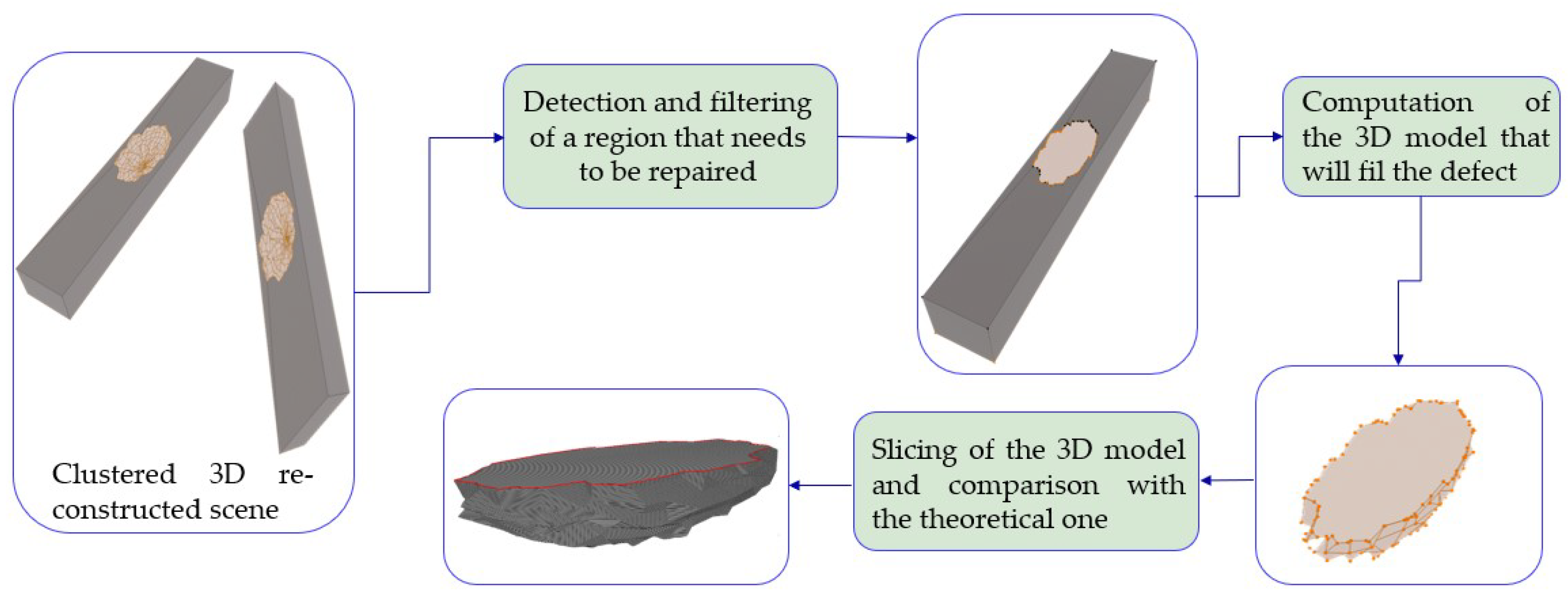
The main concept of the developed methodology regarding the volumetric modeling of a construction defect is displayed in Figure 2. The first task of the approach is to discover the number of defective regions within the investigated scene and distinguish them. Then, in each detected region, certain filtering algorithms are utilized to clear the scene, providing appropriate 3D mesh models for the upcoming computation of a 3D model that would repair an identified defect. In the next phase of the applied methodology, suitable 3D models are automatically generated based on a projection plane and the shotcrete direction. In addition, these models are registered, aligned on the 3D reconstructed scene, and “sliced” in distinct layers that the robot must cover to repair the examined defect. Finally, the computed 3D models are compared with the corresponding optimal ones, as designed by an experienced engineer, demonstrating the effectiveness of the proposed method.
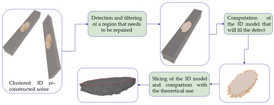
Figure 2.
Workflow of the volumetric modeling approach.
In the context of segmenting the 3D reconstructed scene, derived from the previous chapter, as well as to cluster the regions requiring shotcreting, the density-based spatial clustering of applications with noise (DBSCAN) algorithm was utilized, using the “open3d” library [52]. DBSCAN is a widely used clustering algorithm in machine learning and data mining, renowned for its ability to identify clusters of arbitrary shapes within spatial datasets while remaining resilient to noise [53]. Operating on the principle of density-based clustering, DBSCAN discerns clusters by evaluating the density of data points in proximity to one another. The algorithm progressively extends clusters by incorporating neighboring points into each core point’s cluster until no more points can be added. By prioritizing density over distance, DBSCAN adeptly detects clusters of diverse shapes and sizes, rendering it a versatile tool for segmenting spatial data. Hereupon, it composes a suitable clustering algorithm regarding the distinction of the regions that need to be treated residing in the same scanning scene.
Considering the filtering process of the clustered regions, a method was utilized to eliminate duplicate vertices and faces, aiming to detect and delete redundant or overlapping elements within the clustered 3D mesh. Initially, certain algorithms were employed to compare the vertices of each face to identify duplicates based on [54]. Following the removal of duplicate faces, further cleanup operations were conducted to optimize the mesh structure, ensuring its integrity. The primary objective was to refine the mesh by eliminating unnecessary redundancy, thereby reducing memory usage and ensuring the accuracy of subsequent mesh processing operations. In the next stage of the filtering process, a function was applied to eliminate small components within the scene that are not directly linked to the examined area. This method evaluates the connectivity between vertices and faces in the mesh, determining which vertices are interconnected and which faces share common vertices. Based on this connectivity analysis, the applied module identifies distinct connected components within the mesh, each representing a set of interconnected vertices and faces. By establishing a threshold for selecting which connected components to retain or discard, the filtering process eliminates the unselected components from the overall mesh. Ultimately, the function outputs the filtered mesh, containing only the connected components that satisfy the specified criteria.
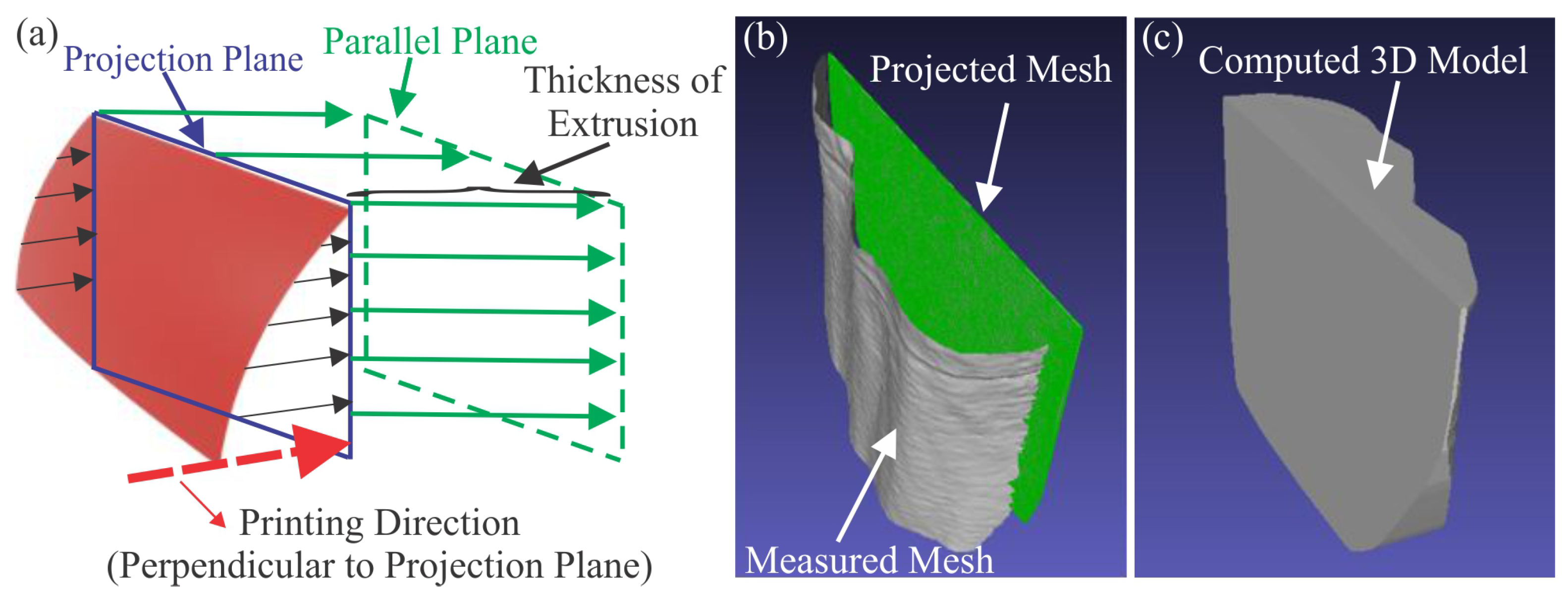
Regarding the isolated areas requiring treatment, the developed volumetric modeling approach aims to generate a suitable 3D model capable of addressing the identified defects. The main concept is illustrated schematically in Figure 3a, where the red surface represents the damaged region of a construction site. In particular, the goal is to automatically generate a 3D model encapsulating the space that needs to be filled in order to restore the examined failure. That can be achieved via the projection of the measured mesh onto a plane that is perpendicular to the direction of the upcoming shotcrete procedure and located in the maximum value of the investigated mesh on the printing axis. Next, considering the surface mesh on the projection plane alongside the magnitudes on the printing axis of the initial mesh, as exhibited in Figure 3b, an appropriate 3D mesh is computed, utilizing the trimesh library [55]. Trimesh is a powerful and versatile library for analyzing triangular meshes, offering functionalities for loading, manipulating, analyzing, and visualizing 3D mesh data efficiently. The automatically generated 3D mesh possesses “negative” geometrical characteristics of the defective region that could fix the encountered defect. In the case of shotcreting, operations take place in the recommended regions, as displayed in Figure 3c. Finally, it must be noted that the introduced volumetric modeling methodology can be adapted in scenarios where the input file comprises a 3D point cloud instead of a mesh.
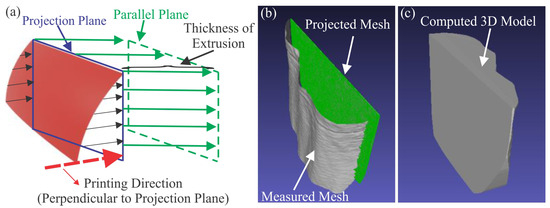
Figure 3.
(a) Main concept of the missing volume computation (b) Typical projected mesh of a defected region and (c) Generated 3D model repairing the defect.
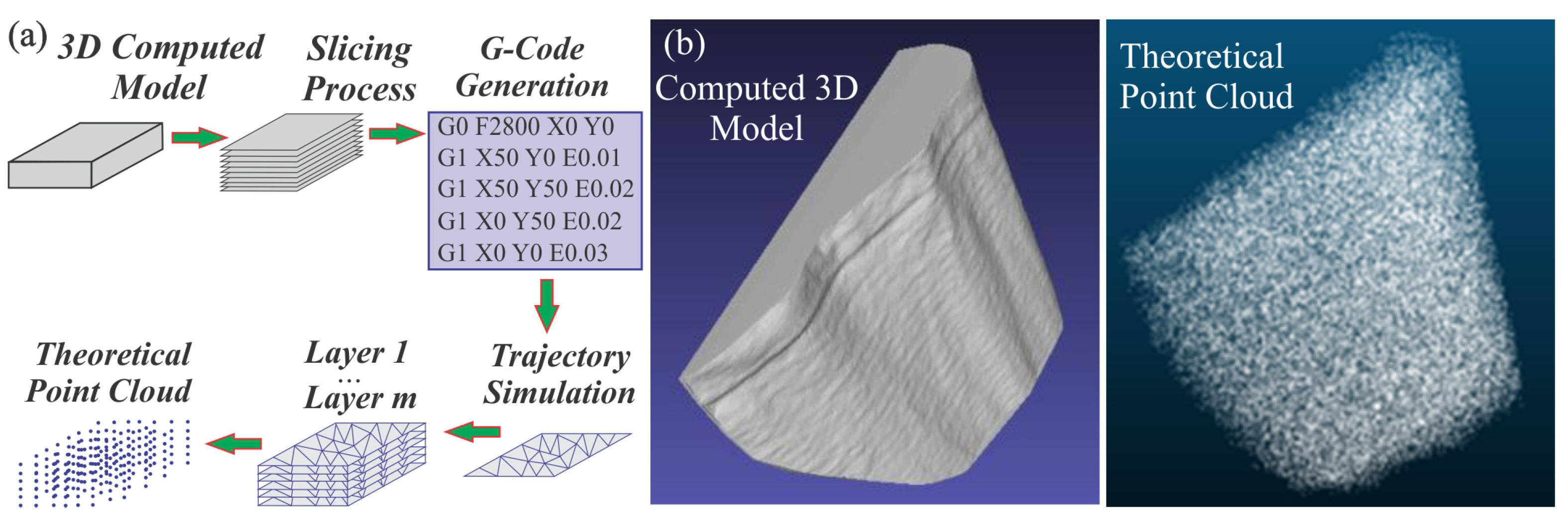
Additive manufacturing (AM) technology enables the production of 3D physical objects utilizing a 3D printer and a digital model. G-code includes instructions for controlling the movement of the nozzle’s actuators, so a method was developed to create an equivalent model based on the calculated volumetric model using the G-code generated by Slic3r software. Initially, the 3D model is automatically imported into the Slic3r software [56], which is a reliable tool for translating 3D models into actionable G-code commands. These commands dictate precise coordinates for the AM machine’s print head to deposit feedstock material, facilitating the creation of the intended structure. Therefore, a simulation was exploited to replicate the movements of the print head through the interpretation of the generated G-code commands. The G-code, as generated by [56], is utilized as an input to systematically analyze each line of the commands, deriving and documenting the paths for the print head to construct the desired geometry. Following this methodology, the computed paths result in the computation of a theoretical point cloud that can be directly correlated with the nozzle’s trajectory. In the final phase of the methodology, the calculated theoretical point cloud is uniformly sampled to assist in determining the nozzle trajectory for the upcoming shotcreting operations, providing a comprehensive digital representation of the entire construction, as illustrated in Figure 4a. Specifically, the point cloud captures the geometric features of the object being constructed in three dimensions, and by analyzing the point cloud data, path planning can be generated to accurately depict its shape and contours. Characteristic outcomes of the above-mentioned technique are displayed in the right part of Figure 4b.
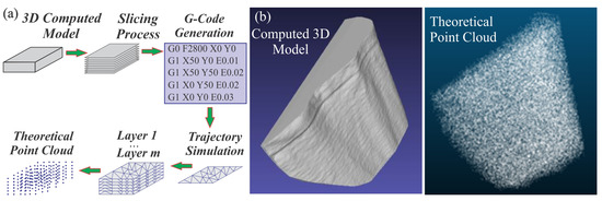
Figure 4.
(a) Theoretical point cloud construction methodology and (b) Typical computed 3D model and its corresponding point cloud representation.
3.4. Integrated System
Our proposed framework features three main components: 3D reconstruction, semantic understanding, and volumetric modeling. The integrated system aims to perceive its surroundings, detect areas of defects, and precisely reconstruct these portions. Subsequently, the volumetric modeling component processes the annotated 3D regions to compute the required volumes. This process is carried out in two steps: first, semantic 3D reconstruction, followed by 3D volume modeling.
During the first phase, the stereo camera streamlines RGB-D images, which are consumed by the 3D reconstruction and semantic understanding components. The semantic understanding module directly accesses the sensor’s raw frames to label the RGB images and provides binary mask images. These are inferred using the YOLOv8m-seg segmentation model with a mask tracking model, SiamMask, connected in series to stabilize the output of the segmentation model trained in a low-data regimen. This creates a robust algorithm capable of identifying exposed reinforcement bars. The depth images are not used here.
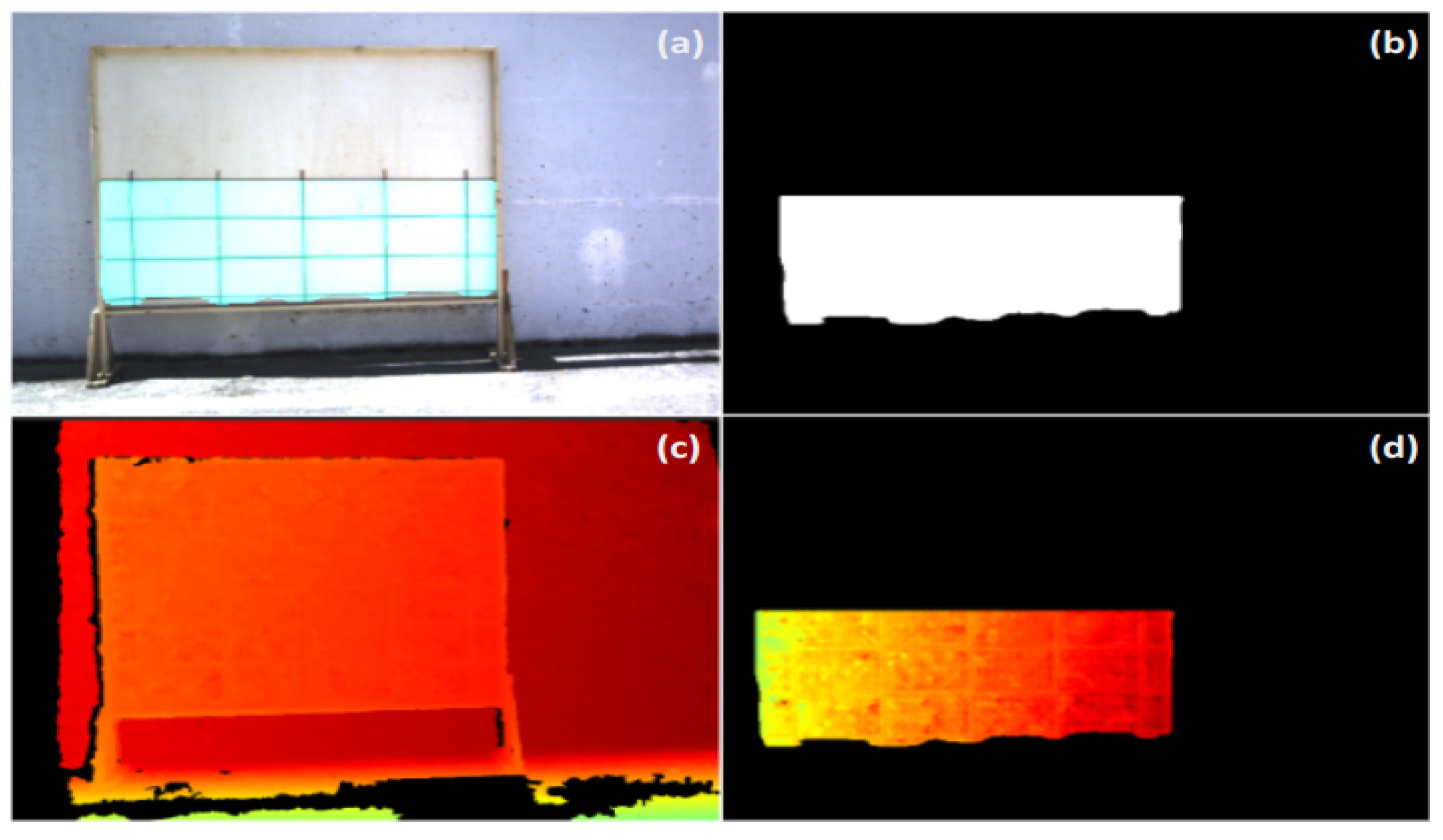
Unlike the semantic understanding process, the 3D reconstruction process uses both RGB and depth images in the form of two different sequences. The first sequence of RGB-D data corresponds to the sensor’s raw frames, which are utilized to calculate odometry estimation via RTAB-Map. Simultaneously, InfiniTAM uses a second sequence, which is created by the mask images and the cropped mask-based depth images, as shown in Figure 5b,d. In essence, when the mask image is generated, the corresponding depth image from the sensor is adjusted to align with this mask. Consequently, depth pixels are mapped to regions where the mask indicates presence (Figure 5b), while areas labeled as zero in the mask correspond to zero-depth regions, as depicted in Figure 5d. This pinpoints the utilization of different data channels for the odometry estimation and synthesis of the 3D model, as regions of interest identified by the semantic segmentation module may be widely dispersed, leading to the intermittent presence of zero values or even entire black frames from zero pixels. Unavoidably, this would have disrupted the consistency of the overall visual odometry estimation, resulting in corrupted 3D models. Hence, the deployment of these two standalone components in 3D reconstruction is particularly critical. Finally, the outcome of this phase is the depiction of a 3D model representing n areas featuring exposed reinforcement bars.
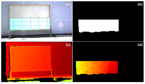
Figure 5.
(a) Cyan-labeled mask area in RGB encoding. (b) Corresponding mask area in binary format. (c) Sensor’s raw depth image. (d) Cropped depth image based on binary mask.
As soon as the 3D model is available, the second phase starts with volumetric modeling to divide the initial 3D model into n 3D models, where n is equal to the number of defective areas.
For example, consider a scenario involving two wooden frames with exposed reinforcement bars. In this case, n equals 2, corresponding to the number of defective areas identified for treatment and to be processed by the volumetric modeling process. This step initiates the computation of the negative volume. The series of actions described, starting from the sensor’s RGB-D data, the creation of a semantically annotated 3D model, and ultimately, the generation of 3D volumes corresponding to the required concrete fill for each ROI, demonstrates the consolidation of the structural components of this system.
It deserves to be noted that the deployment strategy entails using the ROS framework to achieve the desired interconnectivity and communication between the various modules.
4. Experimental Evalutation
4.1. Experimental Process
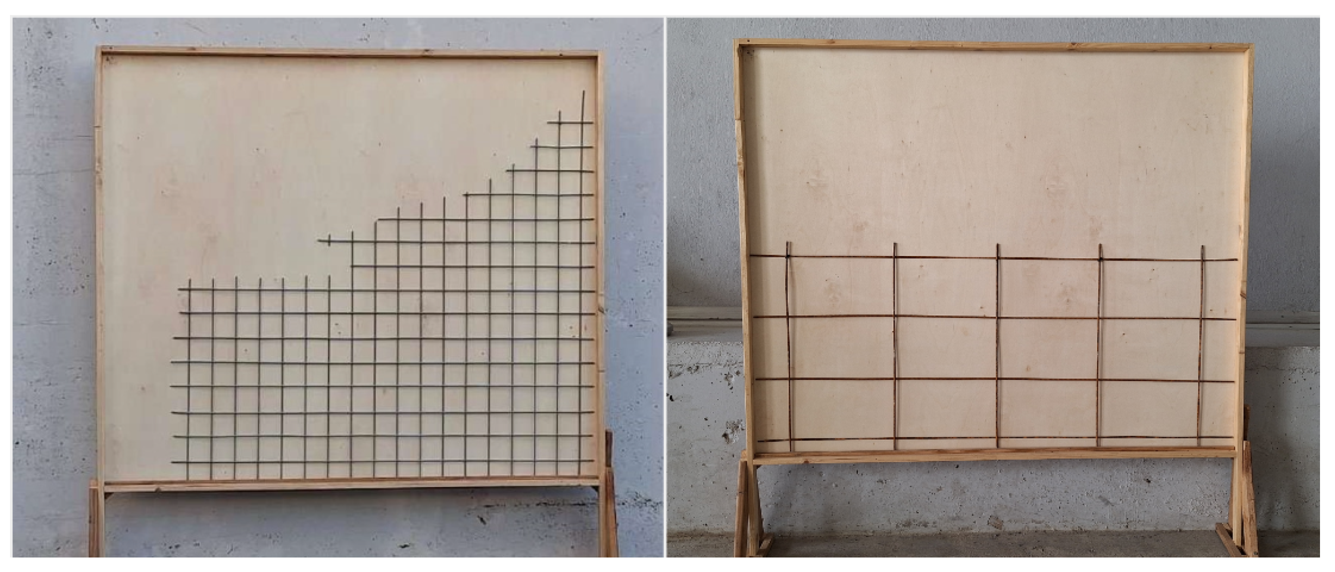
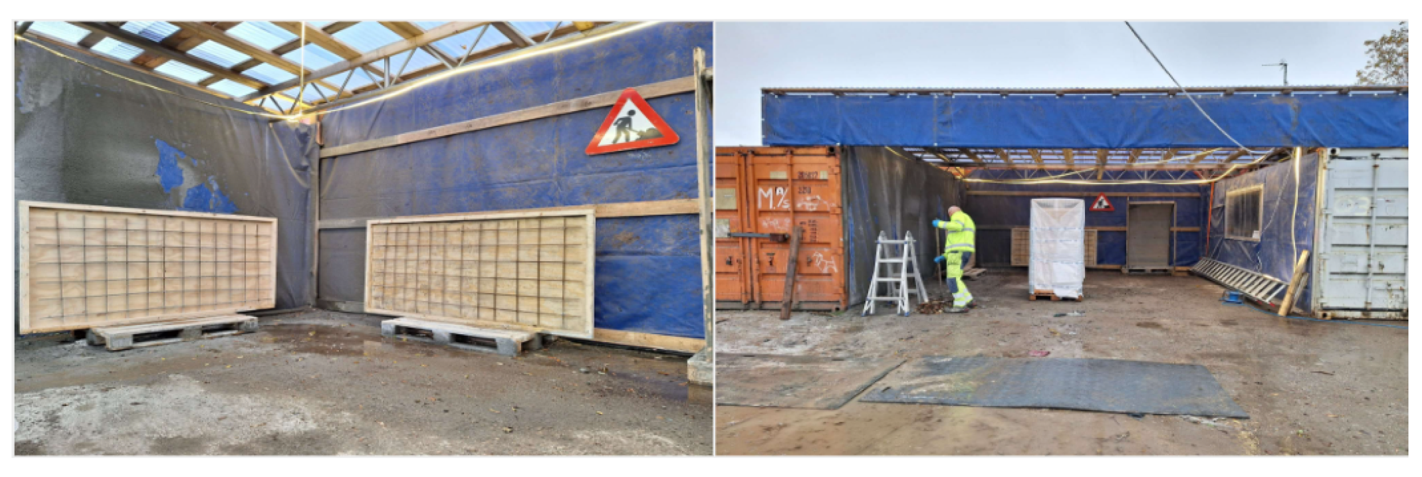
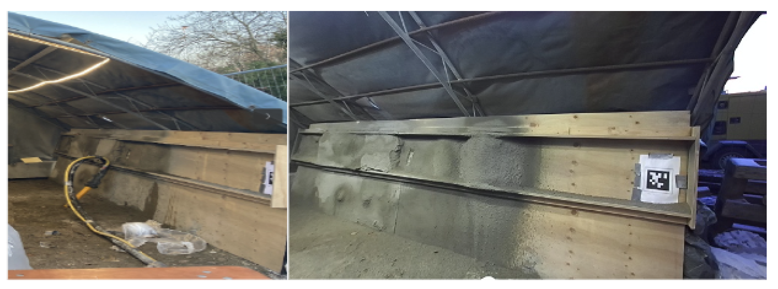
The pipeline underwent rigorous testing at three distinct locations: an outdoor scene in northern Greece, as Testbed-01 (shown in Figure 6), replicating construction-related structures and an actual semi-indoor construction site in Denmark featuring wooden panels with exposed reinforcement bars, as Testbed-02 (shown in Figure 7). Finally, it was tested on a wall presenting significant flaws due to construction imperfections, designated as Testbed-03 (shown in Figure 8).
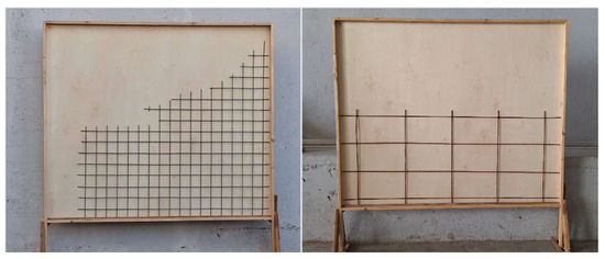
Figure 6.
In the outdoor scene in Greece, the left image shows Testbed 01-a featuring a replica rebar structure, while the right image depicts Testbed 01-b with actual reinforcement bars used in building construction. Both rebars are installed in a custom wooden frame.
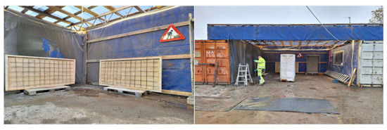
Figure 7.
The semi-indoor scene in Denmark serves as Testbed 02, situated within the construction site. Here, wooden frames with exposed reinforcement bars are prepared for shotcreting.
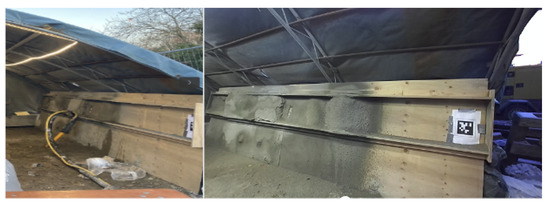
Figure 8.
Testbed 03 is a semi-indoor scene, where the surface presents various flaws requiring proper treatment.
As shown in Figure 6, the first scene was divided into two sessions: Testbed 01-a and Testbed 01-b. In Testbed 01-b, the exposed rebar replication of Testbed 01-a was replaced with wider square shapes commonly used in construction activities. We positioned rebars within the wooden frame to create partial partitions, allowing us to assess the segmentation module’s performance. This setup mirrors real-world construction scenarios, where defects may only affect certain sections of frames. Both sessions of Testbed 01 served as preliminary datasets for experimenting with the sensory setup and its performance. On the other hand, Testbed 02 exhibits a more advanced and complex scenario, as it provides two targets that need to be detected and repaired.
To further evaluate our framework, we conducted an experiment (Testbed 03) that showcases a vertical surface with various imperfections and flows, as illustrated in Figure 8. Here, we consider this area to be a defective region of interest that requires treatment. Note that, the semantic segmentation module was not enabled in this scenario, as there were no exposed rebars. Overall, the types of defects considered in our study include surfaces that expose reinforcement bars either partially or entirely. Furthermore, we examined surfaces with imperfections caused by improper construction or inadequate repair. Such defects mirror real-world challenges that are typically met in the construction and repair activities of ground support walls and bridges [9]. Their repair is critical, as they affect the structural integrity and threaten the durability of civil infrastructures. By targeting these specific defects, our study addresses practical scenarios to ensure the safety and longevity of construction projects.
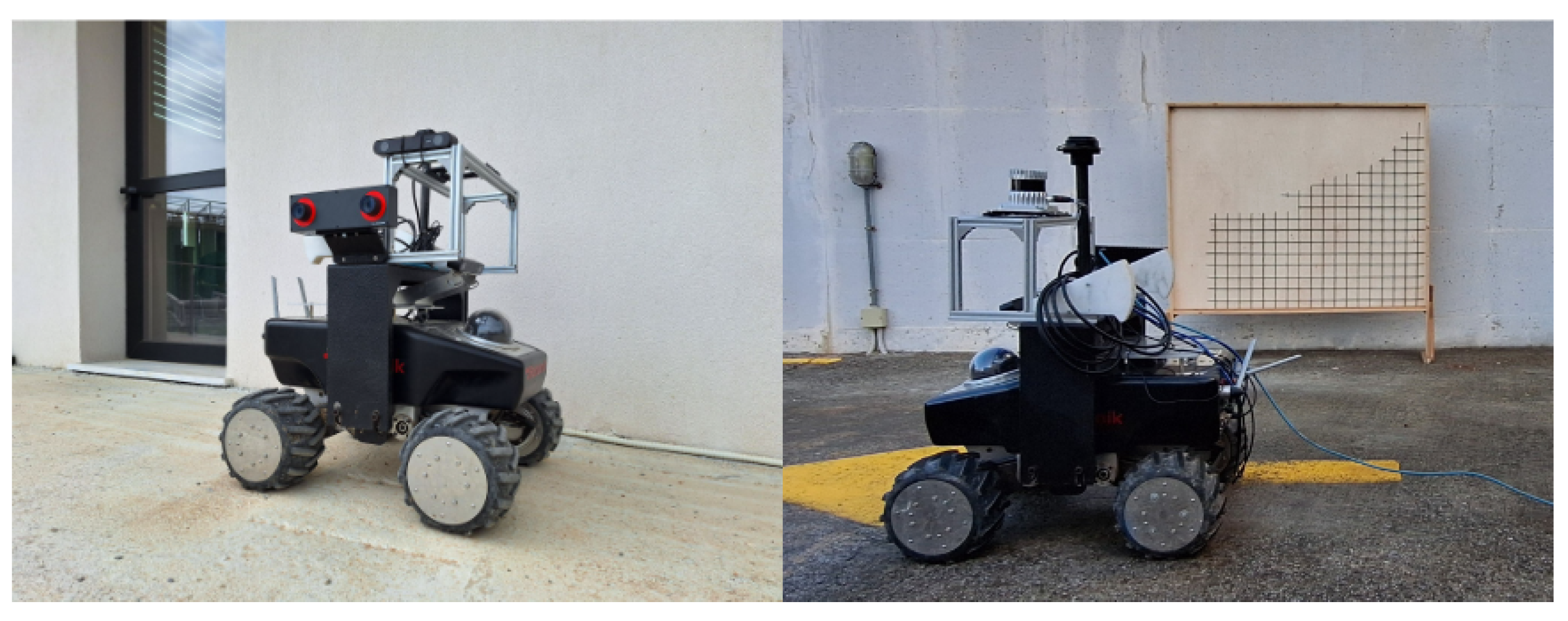
In terms of the sensors deployed, we utilized a RC-Visard 160 stereo sensor manufactured by Roboception (Munich, Germany) that excels in calculating accurate disparity maps in good lighting conditions. The device is designed for close viewing distances, delivering the highest precision within a range of 0.5 m to 3 m. During the data acquisition process, the stereo camera captured RGB-D frames at 1280 × 960 resolution, while mounted on the side of a mobile platform. The mobile robot used was the Summit XL produced by Robotnik (Valencia, Spain) as depicted in Figure 9. It was tele-operated to scan the area at a linear velocity of 0.30 m/s. The robot maintained a constant distance of 2.5 m from the target, which was experimentally determined to optimize the accuracy of depth measurements from the stereo camera. Compared to a hand-held sensor setup, which is prone to variability, the integration of the vision system with the mobile robot ensured more consistent and reliable results. Following this, this setup allowed us to analyze, optimize, and standardize the performance of the vision system.
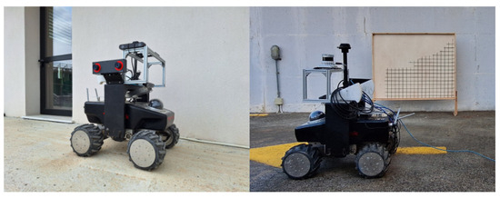
Figure 9.
On the left: Robotnik Summit XL platform equipped with a Roboception RC-Visard 160 stereo camera mounted on the side. On the right: real-time testing of the integrated system during the experimental session in Testbed 01-a.
It is worth noting that, in all three scenes, significant variations in illumination conditions were encountered during scanning. Specifically, in the actual construction site scenarios, supplementary artificial lighting was installed in the scene’s ceilings, as shown in the left images of Figure 7 and Figure 8. The combination of this lighting and occasional direct sunlight exposure in the regions of interest posed challenges for the stereo camera’s precision due to the presence of certain shading points. To tackle these challenges, we experimented with various camera settings and orientations to identify the most suitable setup for accurate depth estimation. Specifically, we found that tilting the camera significantly improved the estimation of the depth measurements by reducing direct sunlight interference and enhancing coverage of shaded areas.
4.2. Results
Prior to testing the entire integrated system, it was crucial for us to conduct experiments on the semantic 3D reconstruction sub-system and evaluate the performance of each component. Following this, the next section discusses the results of semantic 3D reconstruction performance from each viewpoint, while the subsequent section further presents the outcomes as processed by our integrated framework.
4.2.1. Evaluation of Semantic and 3D Reconstruction Components
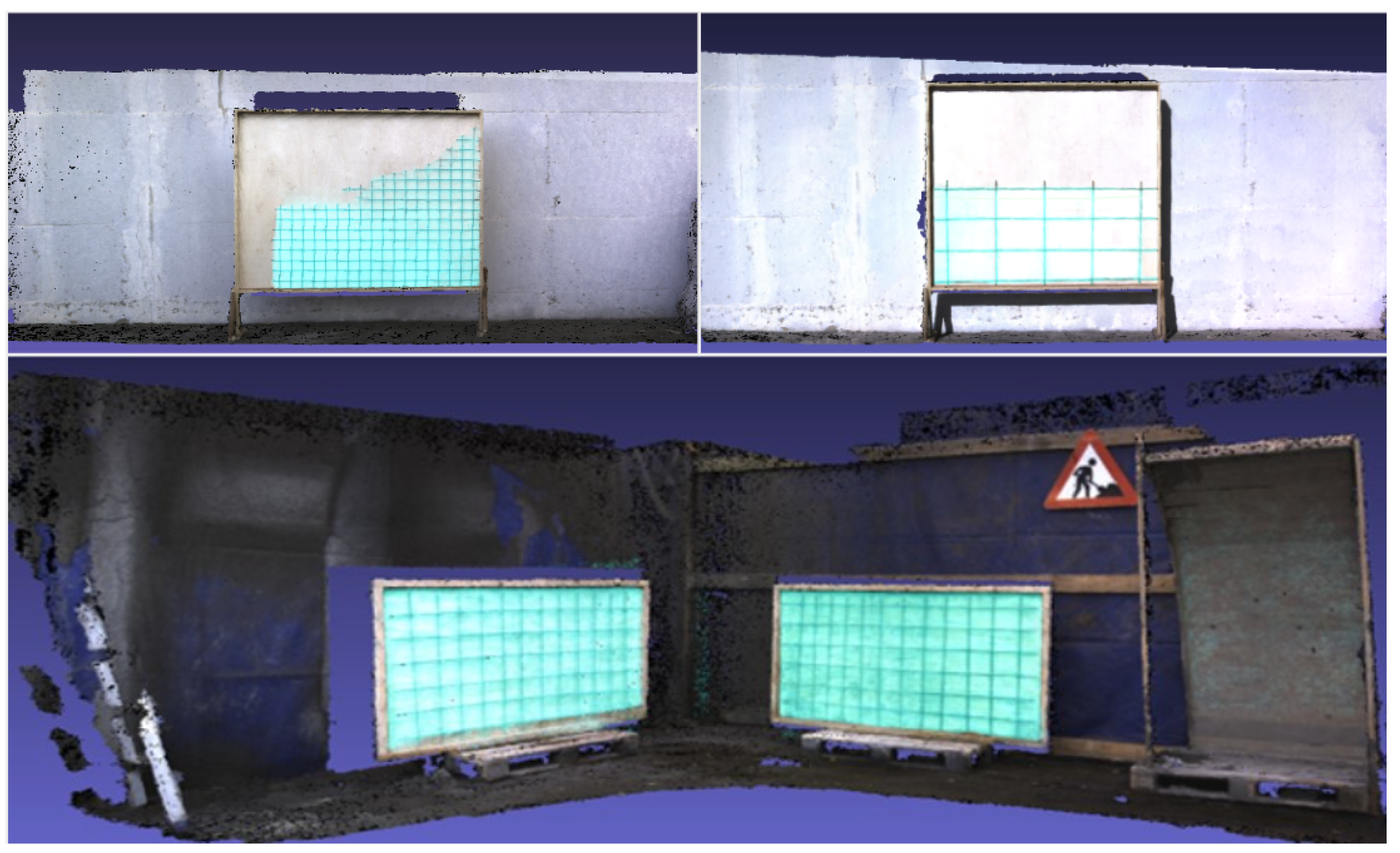
As previously mentioned, the objective of this system is to utilize its perception system, reconstruct semantically annotated ROIs, and create the desired 3D volumes for these areas to be filled. However, considering the evaluation of each component, we found it necessary to reconstruct the entire scene. Practically, this implies that instead of using pairs of binary masks and depth images (as shown in Figure 5b,d), we fed the semantic 3D reconstruction subsystem with pairs of masked RGB and raw depth images (as shown in Figure 5a,c). As depicted in Figure 10, the results in both datasets revealed that the semantic understanding module precisely detected areas of defects labeled as cyan-color regions. Experiments conducted in [51] show that the semantic segmentation module (model and tracker combined) can achieve a mean intersection over union (mIOU), also known as the Jaccard index, of 0.88 when tested on Testbed 02.
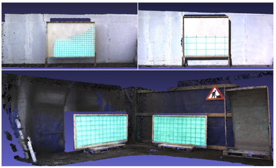
Figure 10.
Three-dimensional views of semantic 3D reconstruction. Top sequence: results for Testbed 01-a (left) and Testbed 01-b (right). Bottom sequence: results for Testbed 02.
From the viewpoint of 3D reconstruction, as shown in Figure 10, the 3D scenes of both testbeds retain rich and textured details, accurately capturing the intricate geometry of the depicted shapes. Our approach effectively avoids the drift pose effect, which refers to the gradual accumulation of deviations in the estimated position and orientation as the vision system moves through the environment. Over time, these accumulated errors can potentially cause misalignments, leading to the appearance of artifacts in the reconstructed model and ultimately distorting the performance of 3D reconstruction. Here, precise odometry estimation and accurate depth measurements were critically important in avoiding this effect. Hence, there are no misalignments or duplicates of the wooden panels, which is a common issue in online 3D reconstruction approaches [23,57]. To quantitatively assess our findings, we carried out a manual process of measuring several point-to-point distances of the reconstructed ROIs to compare them with the actual dimensions of the recorded wooden frames. As a result, our evaluation revealed that the root mean square error (RMSE) amounted to 5.64 mm, as presented in Ref. [51], computed by 12 experimental point-to-point measurements in the 3D model.
Furthermore, a detailed evaluation of our 3D reconstruction method as a standalone component was provided in our previous study [50]. In Ref. [50], the approach was tested using custom-made construction datasets and evaluated based on ground truth 3D models extracted by a high-resolution FARO Focus S-150 terrestrial laser scanner. It yielded highly accurate results, achieving a fitness score of 95% when comparing the ground truth to the test 3D models.
Overall, the semantic 3D reconstruction sub-system demonstrated its robustness and effectiveness in constructing 3D scenes and identifying areas with reinforcement bars. Both components were rigorously tested in several construction scenes and proved their effectiveness.
4.2.2. Results Analysis of the Proposed Framework
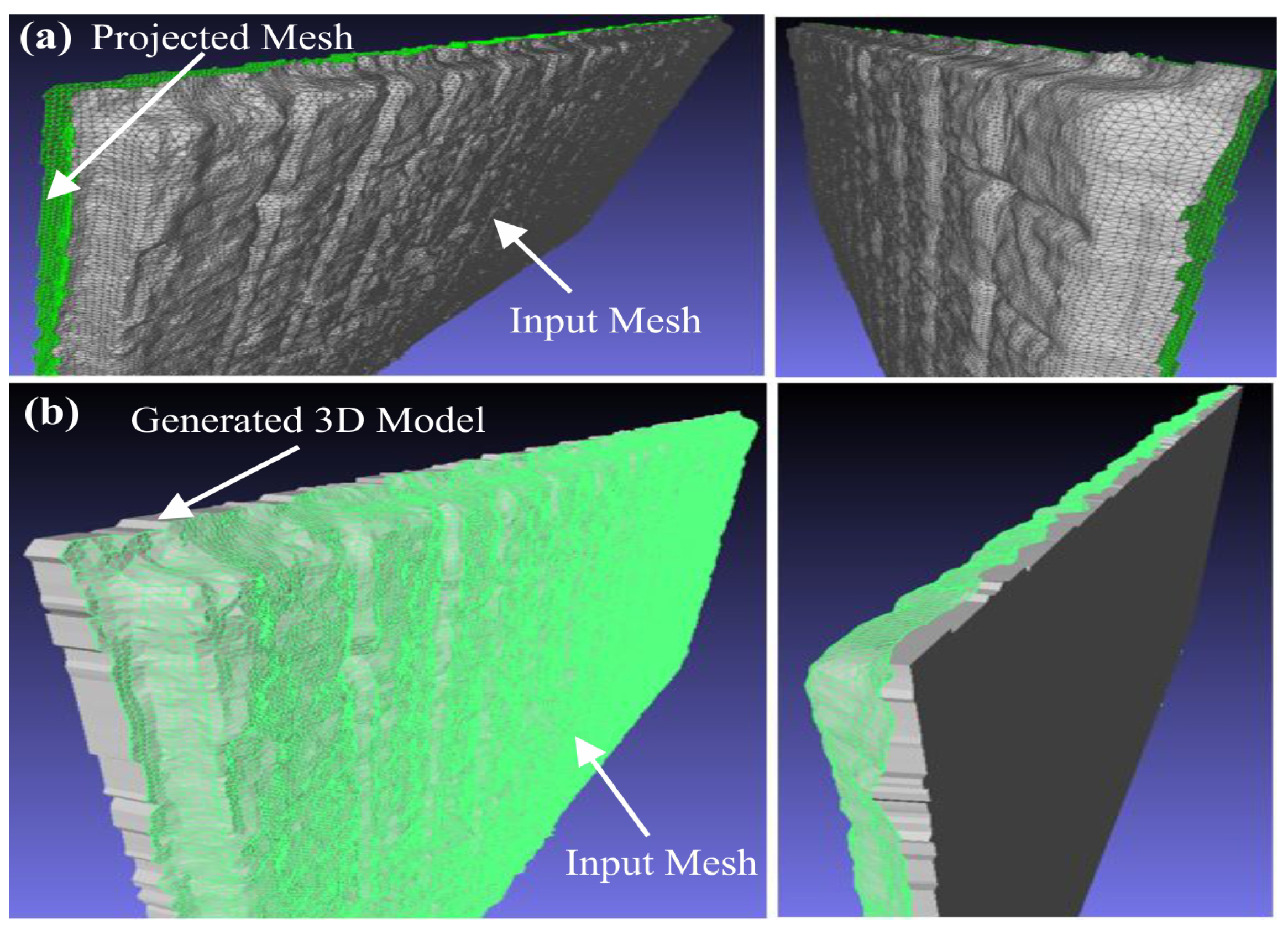
In Figure 11a, the 3D reconstructed scene showcases wooden construction panels, with exposed rebars visible only on one side of the structure, as well as the defective wall. Furthermore, the figure illustrates the results of projecting the analyzed mesh into a plane perpendicular to the forthcoming shotcrete direction. The green meshes in Figure 11a depict the projected vertices and faces derived from the original measured scene, which are subsequently filtered and sampled to reduce mesh size while retaining crucial data from the initial scene. In the subsequent step of the methodology, a 3D mesh is generated by considering the projected mesh and the distance between each vertex and its corresponding on the input scene. The outcomes of this process are demonstrated in Figure 11b, where the computed volume is superimposed onto the input scene, supporting various applications such as trajectory planning and aiding decision-making processes regarding surface quality.
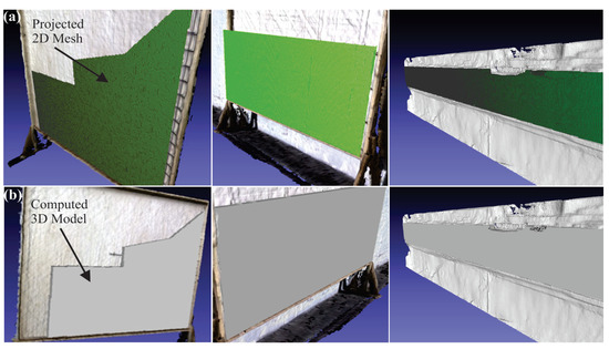
Figure 11.
(a) Projected mesh of the investigated cases and (b) registered 3D generated models on the input scenes.
By aligning sensor data with a predefined reference frame or map, robots employed in shotcrete applications can navigate more efficiently and make well-informed decisions about their surroundings.
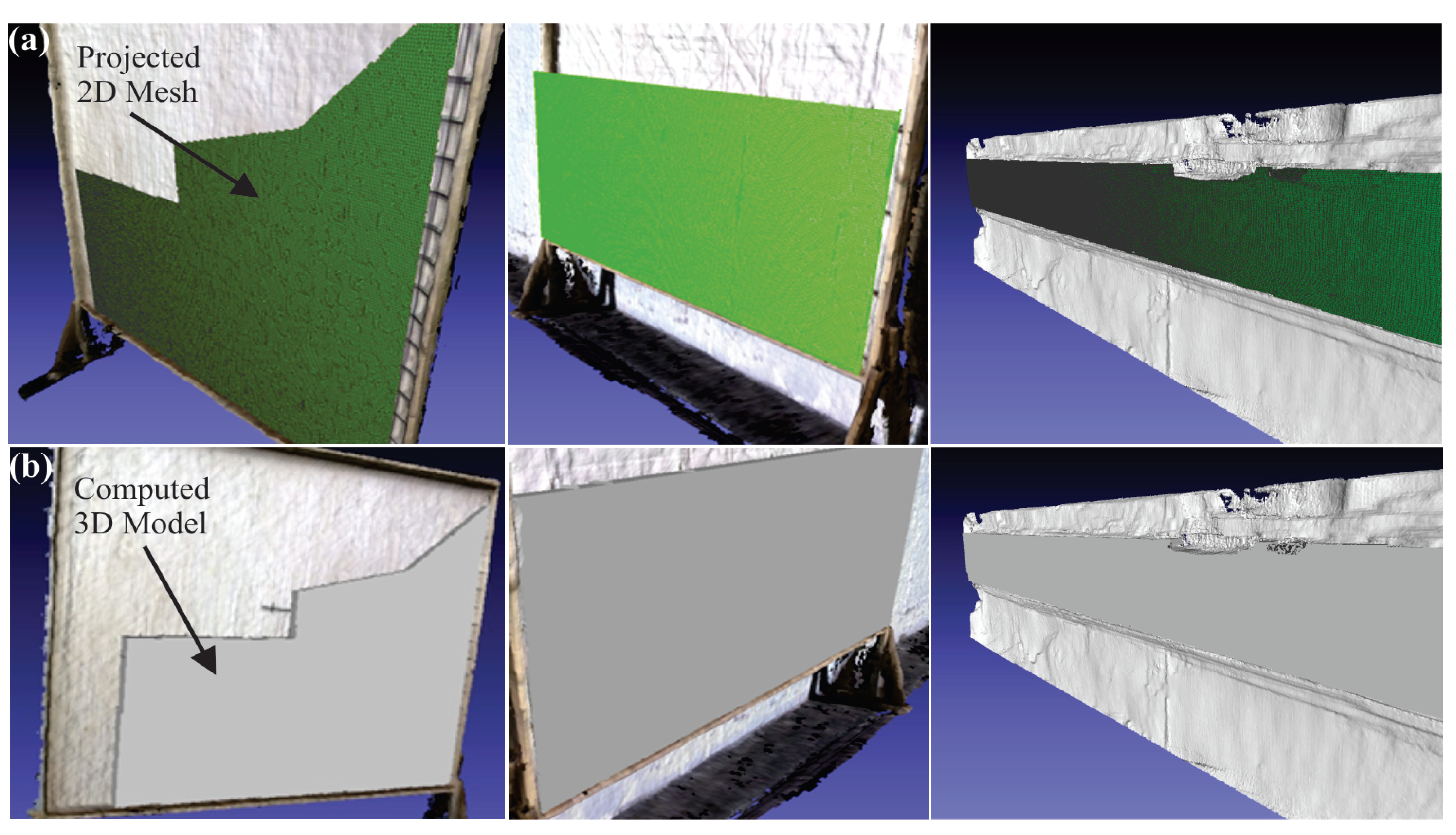
In the next investigated scenario, multiple regions of interest are present within the 3D reconstructed scene, hence the DBSCAN clustering algorithm was initially utilized to identify and isolate all regions requiring repair. The methodology regarding volumetric modeling requires a scene that contains only one area that needs treatment as input, hence the clustering of the segmented regions into separately meaningful areas is necessary. Each wooden panel is treated independently, and two “negative” 3D models should be formulated so the identified constructions can be handled individually to compute the respective volumes requiring shotcreting for repairing the detected defects. The projection of the 3D mesh onto a plane involved transforming the vertices of the mesh from their 3D coordinates to 2D coordinates on a projection plane while preserving the shape and relative positions of the mesh, as exhibited in Figure 12a. The plane selection was determined by a normal vector parallel to the desired printing direction and a spatial point with the maximum value along that specific axis. Each vertex of the 3D mesh was transformed to project its 3D coordinates onto the chosen plane, replacing their original 3D coordinates with corresponding 2D coordinates on the projection plane, thereby “flattening” the mesh onto the plane effectively. Subsequently, the 2D mesh was extruded opposite to the printing direction to form a “closed” 3D model, linking the projected 2D mesh and the initial segmented 3D surface mesh. The result of this process in each segment of the investigated scene is depicted in Figure 12b, where it is evident that the generated volumes connect the clustered meshes with the projected meshes, providing the location as well as the volume of concrete requiring shotcreting.
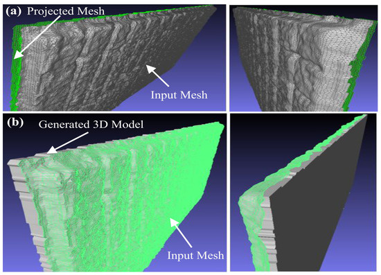
Figure 12.
(a) Computation of the projected mesh in each defected region and (b) generation of the appropriate 3D model on the scene with multiple defects.
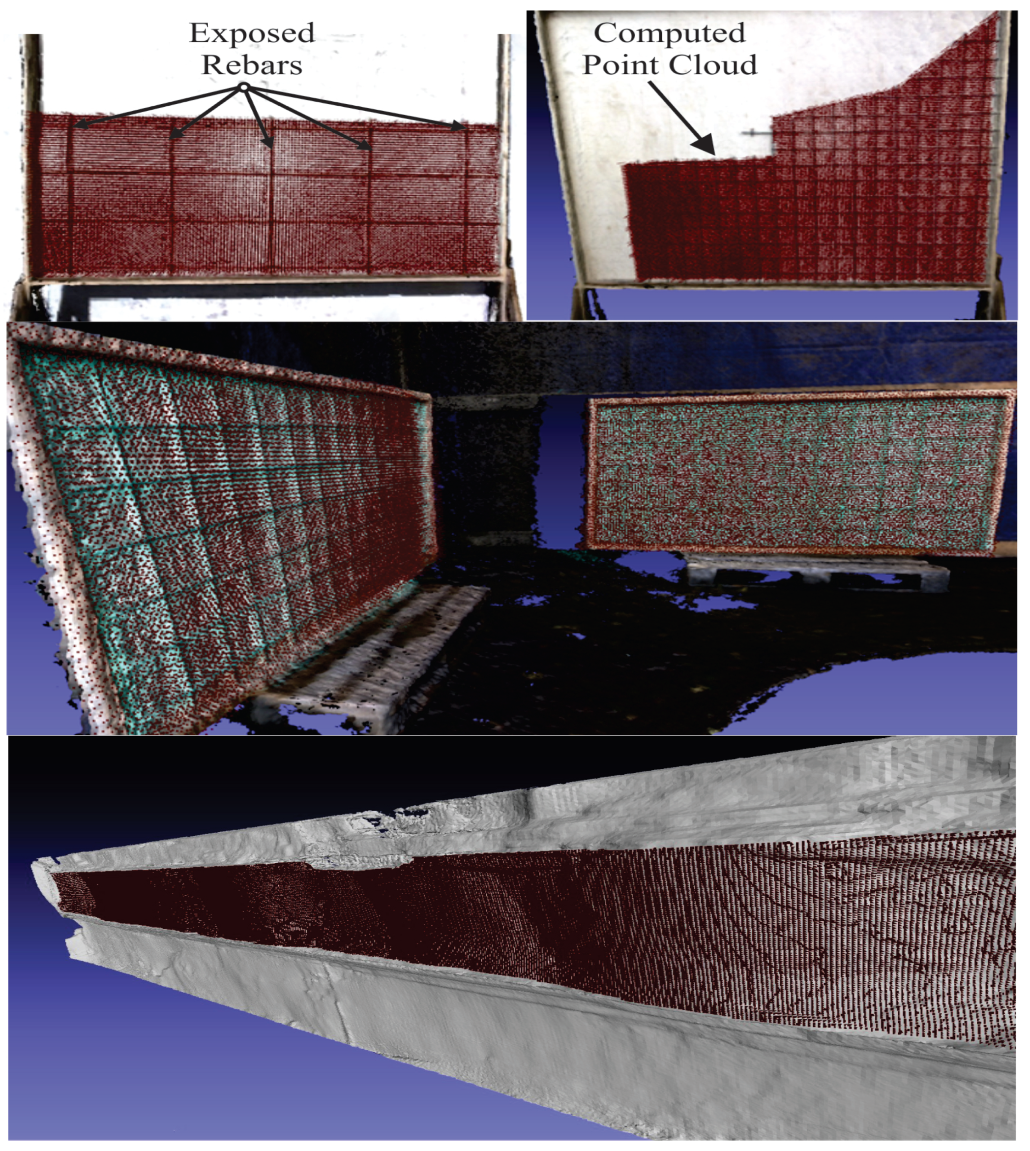
The registration and alignment of the computed 3D models and the corresponding theoretical point clouds with the captured 3D reconstructed scene are crucial tasks to confine the shotcrete application solely to the intended area, thereby reducing waste and minimizing rework requirements. Accurate targeting of the specific region of interest contributes to achieving the desired structural integrity and performance of the repaired structure. Moreover, the precise knowledge of the shotcrete application locations facilitates thorough inspection and quality control during the deposition process. These inspection tools can verify the correct and uniform application of shotcrete to the designated area, ensuring compliance with required standards and specifications. Hereupon, accurate location instructions enable the efficient planning and execution of the shotcreting process, optimizing material usage, equipment deployment, and workflow management, ultimately leading to cost savings and timely project completion. Considering these factors, the point clouds of the 3D models that will repair a defect are aligned within the input scene of the 3D reconstruction stage, as depicted in Figure 13. It is important to highlight that due to the point cloud computation being based on extracting movement commands from G-code, the resulting point cloud does not solely consist of the vertices representing the external geometrical features of the 3D model. In addition to these external points, the generated 3D point incorporates the internal points of the examined geometry. This resource facilitates the generation of the nozzle trajectory to cover the entire volume requiring treatment during shotcreting operations.
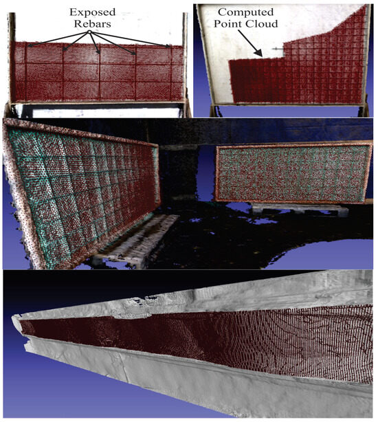
Figure 13.
Registration and alignment of the generated point clouds in the 3D reconstructed scene.
In construction engineering, it is essential to verify the dimensional tolerances of a building construction, thereby certifying its dimensional variations compared to the computed aided design (CAD) model is of primary importance. Comparing the dimensions obtained from the introduced automatic modeling approach with the corresponding ones derived from the blueprint design, quality control engineers can ensure that the constructed structure meets quality standards. In this section, typical results regarding the validation of the volumetric modeling process are demonstrated. Specifically, a comparison is conducted between the generated 3D model and a corresponding one that was manually designed. The designed component represents the actual non-defective region of all the investigated cases, so minor differences between these two models shall validate the effectiveness of the proposed solution. The metrics used to validate the suggested methodology include the computation of the mean absolute error (MAE) and root mean square error (RMSE) between the two 3D models. The criteria for the performance of the volumetric modeling methodology are calculated from the following equations:
where N is the total number of vertices on the computed mesh, and is the distance between the examined vertex of the computed mesh and its corresponding one from the theoretical model.
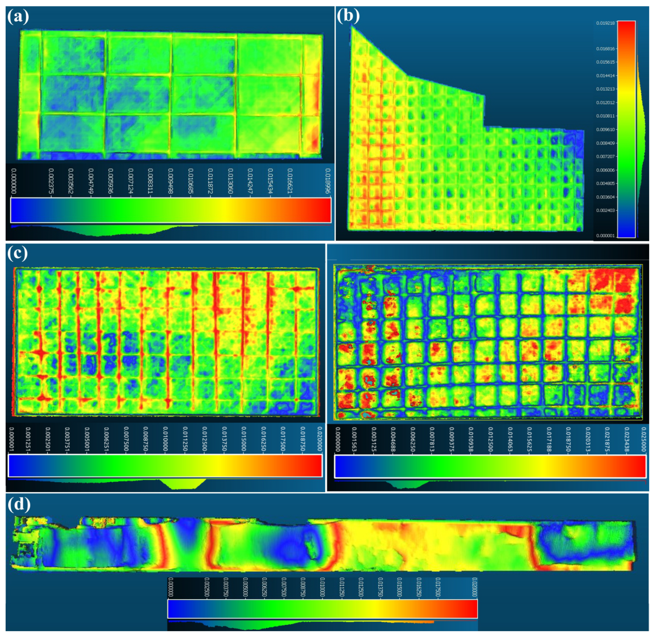
Results of the utilized dimensional metrics are exhibited in Table 1 for all the investigated use cases. The metrics and the deviation results for the examined scenarios were computed with the aid of the Cloud-Compare (CC) software. It is a robust and open-source software suitable for mesh and point cloud processing. The colormaps displayed in Figure 14 indicate that red areas represent locations with the highest dimensional deviation, while dark blue regions indicate areas with minimal deviation. Specifically, the colormap represents the dimensional accuracy between the automatically generated 3D model and a manually designed one by an engineer, aiming to repair the investigated defects. In general, the deviations between the outcomes of the implemented system and the manually designed one are relatively minor. Particularly, the majority of absolute deviations were under 20 mm. The highest MAE was observed in Testbed 01-a, measuring 14.5 mm.

Table 1.
Accuracy of dimensional metrics across each investigated scenario. In Testbed 02, (LR) and (RR) denote left rebar and right rebar, respectively.
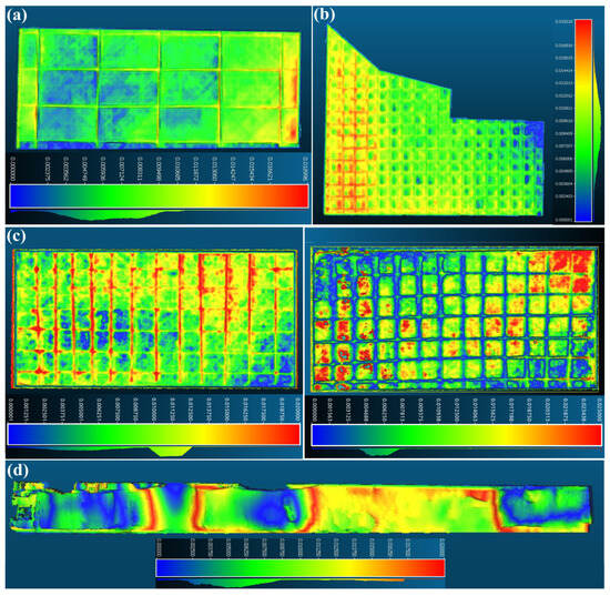
Figure 14.
Comparison between the automatically computed 3D models and the theoretical ones for (a) Testbed 01-b, (b) Testbed 01-a, (c) Testbed 02 (LR) and Testbed 02 (RR), (d) Testbed 03.
The outcomes of the testbeds featuring two wooden panels with exposed rebars in the entire construction (Testbed 02) are depicted in the middle part of Figure 14. The upper part of the figure illustrates the results concerning the wooden panels with the orthogonal and polygonal-shape reinforcement mesh, while the bottom part exhibits the wall with construction flaws. These findings underscore the satisfactory dimensional accuracy of the developed volumetric modeling procedure. It is noteworthy that the proposed system employs a fully automatic procedure for creation, alignment, and registration. Regarding relatively minor deviations, the comparison results validated the efficiency of the proposed system and confirmed its capability to generate the appropriate 3D model for repairing detected defects.
5. Conclusions
In this study, we proposed an online framework applied in robotics, capable of autonomous volumetric modeling based on semantic 3D reconstruction of defected areas that need to be filled with concrete. Our system relies on a robust semantic understanding module using a custom YOLOv8m-seg segmentation model and the SiamMask mask tracker, combined with a dual-component 3D reconstruction approach based on RTAB-Map and InfiniTAM. In addition, an efficient method that considers 3D scan data and corresponding regions of interest containing defects was developed to calculate the precise volume of shotcrete required for repairs. This minimizes material waste and ensures structural integrity. The experimental evaluation of this system showcased that our framework can be adapted in semi-indoor and outdoor construction scenes, as it can effectively and precisely create 3D volumes for each of the defective areas. Specifically, the maximum mean error regarding the dimensional deviations between the automatically computed 3D model and the corresponding theoretical model is less than 15 mm. This reveals that the suggested volumetric modeling approach can capture small details of the investigated scene, thereby generating an appropriate 3D model to treat the examined defect. As this study provides valuable insights into shotcrete applications, we hope to inspire similar studies towards the automation of the construction industry.
Concerning the limitations of our work, our approach heavily relies on the performance of a stereo sensor. Challenging illumination conditions may hinder its effectiveness. Under conditions of low illumination, the deployment of 3D LiDARs would be a more reliable solution to estimate depth.
Author Contributions
Conceptualization, D.K. and P.C.; methodology, D.K., P.C., P.S. and I.K.; software, D.K., P.C. and P.S.; validation, P.C. and D.K.; formal analysis, P.C. and I.K.; investigation, D.K., P.C. and I.K.; resources, I.K. and L.N.; data curation, D.K., P.C. and P.S.; writing—original draft preparation, D.K., P.C. and P.S.; writing—review and editing, I.K., L.N. and D.G.; visualization, D.K., P.C., P.S. and D.G.; supervision, D.G. and D.T.; project administration, D.G. and D.T. All authors have read and agreed to the published version of the manuscript.
Funding
This research received no external funding.
Data Availability Statement
Data are contained within the article.
Acknowledgments
This work was funded and supported by the EU Horizon Europe project “RobetArme” under Grant Agreement 101058731. We extend our gratitude to Christiansen and Essenbaek A/S (CEAS) for providing access to their premises and for the mock-up construction site.
Conflicts of Interest
The authors declare no conflict of interest.
References
- Xu, Z.; Li, S.; Li, H.; Li, Q. Modeling and problem solving of building defects using point clouds and enhanced case-based reasoning. Autom. Constr. 2018, 96, 40–54. [Google Scholar] [CrossRef]
- Ma, Z.; Liu, S. A review of 3D reconstruction techniques in civil engineering and their applications. Adv. Eng. Inform. 2018, 37, 163–174. [Google Scholar] [CrossRef]
- Faqih, F.; Zayed, T. Defect-based building condition assessment. Build. Environ. 2021, 191, 107575. [Google Scholar] [CrossRef]
- Xiaoping, L.; Yupeng, W.; Yao, L.; Xiaotian, G.; Bibo, S. Qiyun Pagoda 3D Model Reconstruction Based on Laser Cloud Data. Surv. Mapp. 2011, 9, 11–14. [Google Scholar]
- Son, H.; Bosché, F.; Kim, C. As-built data acquisition and its use in production monitoring and automated layout of civil infrastructure: A survey. Adv. Eng. Inform. 2015, 29, 172–183. [Google Scholar] [CrossRef]
- Mathavan, S.; Kamal, K.; Rahman, M. A Review of Three-Dimensional Imaging Technologies for Pavement Distress Detection and Measurements. IEEE Trans. Intell. Transp. Syst. 2015, 16, 2353–2362. [Google Scholar] [CrossRef]
- Wang, B.; Wang, Q.; Cheng, J.C.; Song, C.; Yin, C. Vision-assisted BIM reconstruction from 3D LiDAR point clouds for MEP scenes. Autom. Constr. 2022, 133, 103997. [Google Scholar] [CrossRef]
- Yoggy, G.D. The History of Shotcrete; Technical Report; Shotcrete Classics; American Shotcrete Association: Wakefield, MA, USA, 2002. [Google Scholar]
- Kostavelis, I.; Nalpantidis, L.; Detry, R.; Bruyninckx, H.; Billard, A.; Christian, S.; Bosch, M.; Andronikidis, K.; Lund-Nielsen, H.; Yosefipor, P.; et al. RoBétArmé Project: Human-robot Collaborative Construction System for Shotcrete Digitization and Automation through Advanced Perception, Cognition, Mobility and Additive Manufacturing Skills. Open Res. Eur. 2024, 4, 4. [Google Scholar] [CrossRef] [PubMed]
- Valero, E.; Forster, A.; Bosché, F.; Hyslop, E.; Wilson, L.; Turmel, A. Automated defect detection and classification in ashlar masonry walls using machine learning. Autom. Constr. 2019, 106, 102846. [Google Scholar] [CrossRef]
- Dong, W.; Park, J.; Yang, Y.; Kaess, M. GPU Accelerated Robust Scene Reconstruction. In Proceedings of the 2019 IEEE/RSJ International Conference on Intelligent Robots and Systems (IROS), Macau, China, 3–8 November 2019; pp. 7863–7870. [Google Scholar] [CrossRef]
- Huang, H.; Li, L.; Cheng, H.; Yeung, S.K. Photo-SLAM: Real-time Simultaneous Localization and Photorealistic Mapping for Monocular, Stereo, and RGB-D Cameras. arXiv 2024, arXiv:2311.16728. [Google Scholar]
- Schönberger, J.L.; Frahm, J.M. Structure-from-Motion Revisited. In Proceedings of the Conference on Computer Vision and Pattern Recognition (CVPR), Las Vegas, NV, USA, 26 June–1 July 2016. [Google Scholar]
- Mildenhall, B.; Srinivasan, P.P.; Tancik, M.; Barron, J.T.; Ramamoorthi, R.; Ng, R. NeRF: Representing Scenes as Neural Radiance Fields for View Synthesis. Commun. ACM 2020, 65, 99–106. [Google Scholar] [CrossRef]
- Kerbl, B.; Kopanas, G.; Leimkühler, T.; Drettakis, G. 3D Gaussian Splatting for Real-Time Radiance Field Rendering. arXiv 2023, arXiv:2308.04079. [Google Scholar] [CrossRef]
- Müller, T.; Evans, A.; Schied, C.; Keller, A. Instant Neural Graphics Primitives with a Multiresolution Hash Encoding. arXiv 2022, arXiv:2201.05989. [Google Scholar] [CrossRef]
- Matsuki, H.; Murai, R.; Kelly, P.H.J.; Davison, A.J. Gaussian Splatting SLAM. arXiv 2024, arXiv:2312.06741. [Google Scholar]
- Hong, K.; Wang, H.; Yuan, B. Inspection-Nerf: Rendering Multi-Type Local Images for Dam Surface Inspection Task Using Climbing Robot and Neural Radiance Field. Buildings 2023, 13, 213. [Google Scholar] [CrossRef]
- Hachisuka, S.; Tono, A.; Fisher, M. Harbingers of NeRF-to-BIM: A case study of semantic segmentation on building structure with neural radiance fields. In Proceedings of the 2023 European Conference on Computing in Construction 40th International CIB W78 Conference Heraklion, Crete, Greece, 10–12 July 2023. [Google Scholar]
- Keetha, N.; Karhade, J.; Jatavallabhula, K.M.; Yang, G.; Scherer, S.; Ramanan, D.; Luiten, J. SplaTAM: Splat, Track & Map 3D Gaussians for Dense RGB-D SLAM. arXiv 2024, arXiv:2312.02126. [Google Scholar]
- Guédon, A.; Lepetit, V. SuGaR: Surface-Aligned Gaussian Splatting for Efficient 3D Mesh Reconstruction and High-Quality Mesh Rendering. arXiv 2023, arXiv:2311.12775. [Google Scholar]
- Fink, L.; Rückert, D.; Franke, L.; Keinert, J.; Stamminger, M. LiveNVS: Neural View Synthesis on Live RGB-D Streams. In Proceedings of the SIGGRAPH Asia 2023 Conference Papers. ACM, 2023, SA ’23, Sydney, NSW, Australia, 12–15 December 2023. [Google Scholar] [CrossRef]
- Katsatos, D.; Alexiou, D.; Kontodina, T.; Chatzikonstantinou, I.; Kostavelis, I.; Giakoumis, D.; Tzovaras, D. Comparative Study of Surface 3D Reconstruction Methods Applied in Construction Sites. In Proceedings of the 2023 IEEE International Conference on Imaging Systems and Techniques (IST), Copenhagen, Denmark, 17–19 October 2023; IEEE: Piscataway, NJ, USA, 2023; pp. 1–6. [Google Scholar]
- Chung, C.M.; Tseng, Y.C.; Hsu, Y.C.; Shi, X.Q.; Hua, Y.H.; Yeh, J.F.; Chen, W.C.; Chen, Y.T.; Hsu, W.H. Orbeez-SLAM: A Real-time Monocular Visual SLAM with ORB Features and NeRF-realized Mapping. arXiv 2023, arXiv:2209.13274. [Google Scholar]
- Kong, X.; Liu, S.; Taher, M.; Davison, A.J. vMAP: Vectorised Object Mapping for Neural Field SLAM. arXiv 2023, arXiv:2302.01838. [Google Scholar]
- Ha, S.; Yeon, J.; Yu, H. RGBD GS-ICP SLAM. arXiv 2024, arXiv:2403.12550. [Google Scholar]
- Newcombe, R.A.; Izadi, S.; Hilliges, O.; Molyneaux, D.; Kim, D.; Davison, A.J.; Kohi, P.; Shotton, J.; Hodges, S.; Fitzgibbon, A. KinectFusion: Real-time dense surface mapping and tracking. In Proceedings of the 2011 10th IEEE International Symposium on Mixed and Augmented Reality, Basel, Switzerland, 26–29 October 2011; pp. 127–136. [Google Scholar] [CrossRef]
- Whelan, T.; Salas-Moreno, R.F.; Glocker, B.; Davison, A.J.; Leutenegger, S. ElasticFusion: Real-time dense SLAM and light source estimation. Int. Robot. Res. 2016, 35, 1697–1716. [Google Scholar] [CrossRef]
- Prisacariu, V.A.; Kähler, O.; Golodetz, S.; Sapienza, M.; Cavallari, T.; Torr, P.H.S.; Murray, D.W. InfiniTAM v3: A Framework for Large-Scale 3D Reconstruction with Loop Closure. arXiv 2017, arXiv:1708.00783. [Google Scholar]
- Oleynikova, H.; Taylor, Z.; Fehr, M.; Nieto, J.I.; Siegwart, R. Voxblox: Building 3D Signed Distance Fields for Planning. arXiv 2016, arXiv:1611.03631. [Google Scholar]
- Rosinol, A.; Abate, M.; Chang, Y.; Carlone, L. Kimera: An Open-Source Library for Real-Time Metric-Semantic Localization and Mapping. arXiv 2019, arXiv:1910.02490. [Google Scholar]
- Ronneberger, O.; Fischer, P.; Brox, T. U-Net: Convolutional Networks for Biomedical Image Segmentation. arXiv 2015, arXiv:1505.04597. [Google Scholar]
- Chen, L.C.; Papandreou, G.; Schroff, F.; Adam, H. Rethinking Atrous Convolution for Semantic Image Segmentation. arXiv 2017, arXiv:1706.05587. [Google Scholar]
- Zhao, H.; Shi, J.; Qi, X.; Wang, X.; Jia, J. Pyramid Scene Parsing Network. In Proceedings of the 2017 IEEE Conference on Computer Vision and Pattern Recognition (CVPR), Los Alamitos, CA, USA, 21–26 July 2017; pp. 6230–6239. [Google Scholar] [CrossRef]
- Wang, J.; Sun, K.; Cheng, T.; Jiang, B.; Deng, C.; Zhao, Y.; Liu, D.; Mu, Y.; Tan, M.; Wang, X.; et al. Deep High-Resolution Representation Learning for Visual Recognition. arXiv 2019, arXiv:1908.07919. [Google Scholar] [CrossRef] [PubMed]
- Xie, E.; Wang, W.; Yu, Z.; Anandkumar, A.; Alvarez, J.M.; Luo, P. SegFormer: Simple and efficient design for semantic segmentation with transformers. In Advances in Neural Information Processing Systems; Ranzato, M., Beygelzimer, A., Dauphin, Y., Liang, P., Vaughan, J.W., Eds.; Curran Associates, Inc.: Glasgow, UK, 2021; Volume 34, pp. 12077–12090. [Google Scholar]
- Zheng, S.; Lu, J.; Zhao, H.; Zhu, X.; Luo, Z.; Wang, Y.; Fu, Y.; Feng, J.; Xiang, T.; Torr, P.H.; et al. Rethinking Semantic Segmentation from a Sequence-to-Sequence Perspective with Transformers. In Proceedings of the 2021 IEEE/CVF Conference on Computer Vision and Pattern Recognition (CVPR), Nashville, TN, USA, 20–25 June 2021; pp. 6877–6886. [Google Scholar] [CrossRef]
- Cheng, B.; Misra, I.; Schwing, A.G.; Kirillov, A.; Girdhar, R. Masked-attention Mask Transformer for Universal Image Segmentation. In Proceedings of the 2022 IEEE/CVF Conference on Computer Vision and Pattern Recognition (CVPR), New Orleans, LA, USA, 18–24 June 2022; pp. 1280–1289. [Google Scholar] [CrossRef]
- He, K.; Gkioxari, G.; Dollar, P.; Girshick, R. Mask R-CNN. In Proceedings of the 2017 IEEE International Conference on Computer Vision (ICCV), Venice, Italy, 22–29 October 2017; pp. 2980–2988. [Google Scholar] [CrossRef]
- Jocher, G.; Chaurasia, A.; Qiu, J. Ultralytics YOLOv8; Ultralytics Inc.: Frederick, MD, USA, 2023. [Google Scholar]
- Hüthwohl, P.; Lu, R.; Brilakis, I. Multi-classifier for reinforced concrete bridge defects. Autom. Constr. 2019, 105, 102824. [Google Scholar] [CrossRef]
- Mundt, M.; Majumder, S.; Murali, S.; Panetsos, P.; Ramesh, V. Meta-Learning Convolutional Neural Architectures for Multi-Target Concrete Defect Classification with the COncrete Defect Bridge Image Dataset. In Proceedings of the 2019 IEEE/CVF Conference on Computer Vision and Pattern Recognition (CVPR), Long Beach, CA, USA, 15–20 June 2019; pp. 11188–11197. [Google Scholar] [CrossRef]
- Santos, R.; Ribeiro, D.; Lopes, P.; Cabral, R.; Calçada, R. Detection of exposed steel rebars based on deep-learning techniques and unmanned aerial vehicles. Autom. Constr. 2022, 139, 104324. [Google Scholar] [CrossRef]
- Wang, H.; Ye, Z.; Wang, D.; Jiang, H.; Liu, P. Synthetic Datasets for Rebar Instance Segmentation Using Mask R-CNN. Buildings 2023, 13, 585. [Google Scholar] [CrossRef]
- Wang, Q.; Zhang, L.; Bertinetto, L.; Hu, W.; Torr, P.H. Fast Online Object Tracking and Segmentation: A Unifying Approach. In Proceedings of the 2019 IEEE/CVF Conference on Computer Vision and Pattern Recognition (CVPR), Long Beach, CA, USA, 15–20 June 2019; pp. 1328–1338. [Google Scholar] [CrossRef]
- Zhao, S.; Wang, Q.; Fang, X.; Liang, W.; Cao, Y.; Zhao, C.; Li, L.; Liu, C.; Wang, K. Application and Development of Autonomous Robots in Concrete Construction: Challenges and Opportunities. Drones 2022, 6, 424. [Google Scholar] [CrossRef]
- Lin, T.H.; Chang, C.T.; Yang, B.H.; Hung, C.C.; Wen, K.W. AI-powered shotcrete robot for enhancing structural integrity using ultra-high performance concrete and visual recognition. Autom. Constr. 2023, 155, 105038. [Google Scholar] [CrossRef]
- Mariniuc, A.M.; Cojocaru, D.; Abagiu, M.M. Building Surface Defect Detection Using Machine Learning and 3D Scanning Techniques in the Construction Domain. Buildings 2024, 14, 669. [Google Scholar] [CrossRef]
- Tan, Y.; Li, G.; Cai, R.; Ma, J.; Wang, M. Mapping and modelling defect data from UAV captured images to BIM for building external wall inspection. Autom. Constr. 2022, 139, 104284. [Google Scholar] [CrossRef]
- Katsatos, D.; Alexiou, D.; Kontodina, T.; Kostavelis, I.; Giakoumis, D.; Tzovaras, D.; Nalpantidis, L. Real-time 3D Reconstruction Adapted for Robotic Applications in Construction Sites. In Proceedings of the European Robotics Forum 2024: ERF 2024, Rimini, Italy, 13–15 March 2023. [Google Scholar]
- Schmidt, P.; Katsatos, D.; Alexiou, D.; Kostavelis, I.; Giakoumis, D.; Tzovaras, D.; Nalpantidis, L. Towards autonomous shotcrete construction: Semantic 3D reconstruction for concrete deposition using stereo vision and deep learning. In Proceedings of the 41st International Symposium on Automation and Robotics in Construction, Lille, France, 3–7 June 2024; pp. 896–903. [Google Scholar] [CrossRef]
- Zhou, Q.Y.; Park, J.; Koltun, V. Open3D: A Modern Library for 3D Data Processing. arXiv 2018, arXiv:1801.09847. [Google Scholar]
- Ester, M.; Kriegel, H.P.; Sander, J.; Xu, X. A density-based algorithm for discovering clusters in large spatial databases with noise. In Proceedings of the Second International Conference on Knowledge Discovery and Data Mining, KDD’96, Portland, OR, USA, 2–4 August 1996; AAAI Press: Washington, DC, USA, 1996; pp. 226–231. [Google Scholar]
- Muntoni, A.; Cignoni, P. PyMeshLab; CERN: Geneva, Switzerland, 2021. [Google Scholar] [CrossRef]
- Dawson-Haggerty, M. trimesh. 2019. Available online: https://trimesh.org/ (accessed on 10 June 2024).
- Fedorov, A.; Beichel, R.; Kalpathy-Cramer, J.; Finet, J.; Fillion-Robin, J.C.; Pujol, S.; Bauer, C.; Jennings, D.; Fennessy, F.; Sonka, M.; et al. 3D Slicer as an Image Computing Platform for the Quantitative Imaging Network. Magn. Reson. Imaging 2012, 30, 1323–1341. [Google Scholar] [CrossRef]
- Fioraio, N.; Taylor, J.; Fitzgibbon, A.; Di Stefano, L.; Izadi, S. Large-scale and drift-free surface reconstruction using online subvolume registration. In Proceedings of the 2015 IEEE Conference on Computer Vision and Pattern Recognition (CVPR), Boston, MA, USA, 7–12 June 2015; pp. 4475–4483. [Google Scholar] [CrossRef]
Disclaimer/Publisher’s Note: The statements, opinions and data contained in all publications are solely those of the individual author(s) and contributor(s) and not of MDPI and/or the editor(s). MDPI and/or the editor(s) disclaim responsibility for any injury to people or property resulting from any ideas, methods, instructions or products referred to in the content. |
© 2024 by the authors. Licensee MDPI, Basel, Switzerland. This article is an open access article distributed under the terms and conditions of the Creative Commons Attribution (CC BY) license (https://creativecommons.org/licenses/by/4.0/).


