Article

Suitable Method for Improving Friction Performance of Magnetic Wheels with Metal Yokes †

1
Department of Mechanical Engineering, Osaka Metropolitan University, Osaka 599-8531, Japan
2
Measurement Industry Co., Ltd., Osaka 590-0056, Japan
*
Author to whom correspondence should be addressed.
This article is a revised and expanded version of a paper entitled “Improvement of Friction Properties of the Planetary Geared Magnetic Wheels”, which was presented at “International Symposium of the Graduate School of Engineering, Osaka Metropolitan University World-Leading Engineering Research” in Osaka International Convention Center on 20 September 2023. The content of this presentation has not been peer-reviewed. The copyright of the presentation is held by the authors.
Robotics 2024, 13(10), 151; https://doi.org/10.3390/robotics13100151
Submission received: 26 August 2024 / Revised: 26 September 2024 / Accepted: 8 October 2024 / Published: 11 October 2024
(This article belongs to the Section Intelligent Robots and Mechatronics)

Abstract

:
A magnetic-wheeled robot is a type of robot that inspects large steel structures instead of humans, and it can run on a three-dimensional path by using wheels with built-in permanent magnets. For the robots to work safely, their magnetic wheels require both magnetic attractive forces and friction forces. Planetary-geared magnetic wheels, which we have developed, make direct contact with their yokes on the running surface to ensure their magnetic attractive force. However, this design decreases their frictional performance more than common magnetic wheels covered with soft materials. Therefore, the yokes require methods that can improve their frictional performance without decreasing their attractive force. To consider the best method for the use of magnetic wheels, this study has run experiments with five types of yokes, which have different processing. As a result, the yokes with corroded surfaces could have maintained the attractive force more than 90% of the time and increased their traction forces by about 36% in static conditions and about 30% in dynamic conditions compared to yokes with no machining. The main reasons for these experimental results are that the rust layer has stable irregularities on the surface and includes ferromagnetic materials.

1. Introduction

Large-scale plant facilities and infrastructure require regular inspections for early detection and repair of damages [1,2]. However, these inspections are carried out in dangerous and difficult places for humans to access. Such inspections require large equipment or scaffolding, which is costly and time-consuming. To solve these problems, it is important to use robots that can carry out inspection work in the place of humans [3,4,5]. Magnetic-wheeled robots are the type of robots that use wheels with built-in permanent magnets to attract and run on steel structures [6,7,8,9,10]. This type requires no electric power for attraction and, therefore, has a long operating time for robots. It also safely performs tasks that require getting close to the structures. To be used in real-life work, the robots must not fall from these structures and be able to break through complex three-dimensional paths and obstacles.
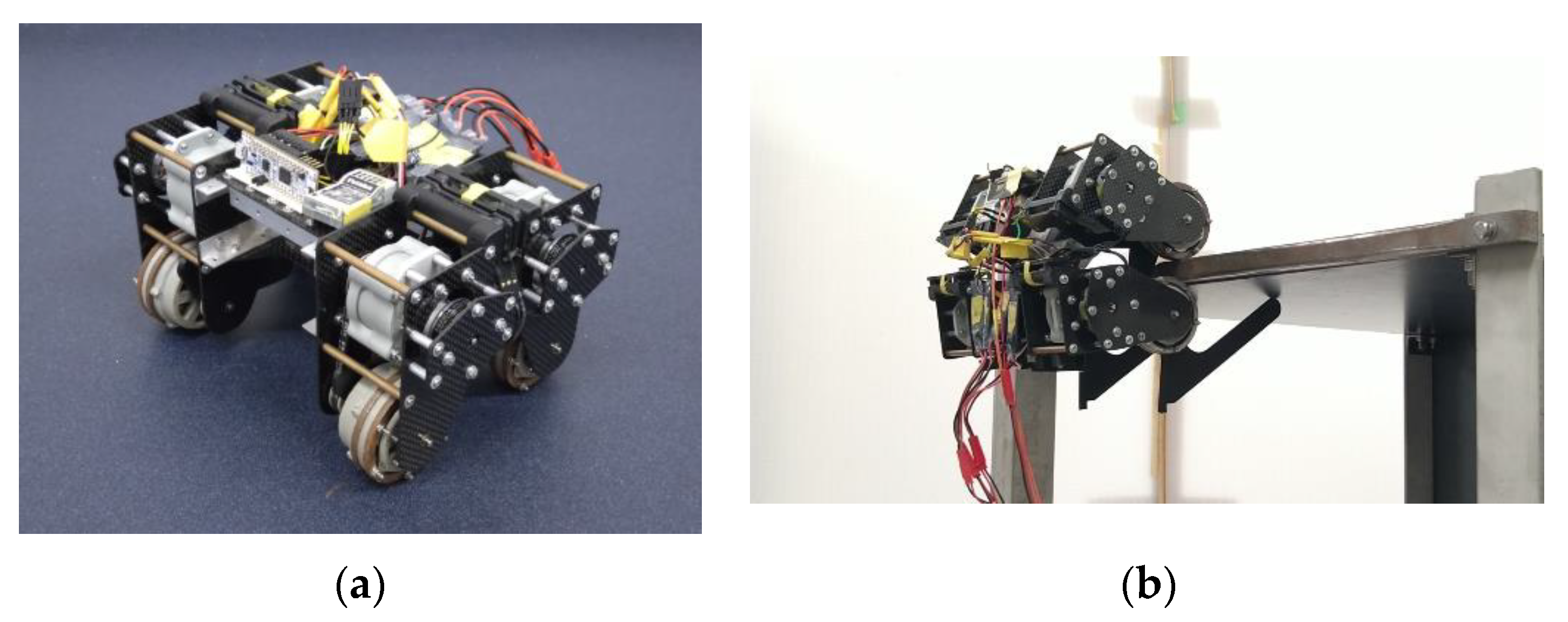
In a previous study, the authors developed a planetary-geared magnetic wheel (PGMW), as shown in Figure 1 and Figure 2. This wheel has a built-in planetary gear mechanism. This mechanism functions to reverse the direction of the motor reaction force and to change the direction of the attractive force. A robot SCPREM-I, as shown in Figure 3, equipped with four PGMWs, can easily break through the flange sections, which are extremely difficult to run over [11,12].
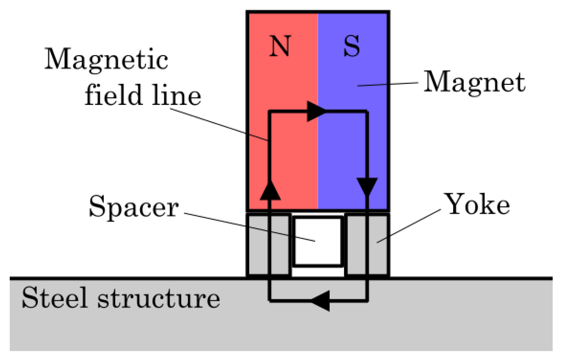
The PGMW includes magnetic yokes for high magnetic attractive power. Yokes are pieces that form a magnetic circuit between the magnets and objects to generate strong, attractive forces. Figure 4 shows the magnetic circuit that formed in the PGMW. The yokes consist of an ABS ring sandwiched between two SS400 rings. Axially magnetized cylindrical neodymium magnets are in contact with the inner surface of the two rings in a bridging. As shown in Figure 4, the magnetic flux from the magnets passes through one side of the yoke, the surface of the steel structure, and back toward the magnets from the yoke on the other side. This is the closed magnetic circuit in the PGMW.
Normally, the yokes are designed to make contact with the magnets in a large area so that more of a magnetic flux can flow. However, the magnets in the PGMWs are placed to roll in the yokes while they keep in contact. This means that the contact area between the magnets and the yoke is very small, and the attractive force obtained is weaker. Therefore, the PGMWs are designed so that the yokes touch the running surface directly to ensure maximum attractive force. However, this design has a low friction against the metallic running surface. If the wheels are slippery on the three-dimensional path, the wheels or the robot will fall off the structure. Therefore, the PGMWs need to be designed to improve friction performance.
Some previous magnetic wheels covered the surface of the yokes with a soft material such as rubber [13]. This improves the friction coefficient of the wheels and prevents the running surface from scratching the yokes. Additionally, these non-magnetic covers reduce the attractive force of the wheels. Such wheels use larger and stronger magnets to ensure sufficient attractive force. However, this common method requires larger wheels and powerful motors for driving. This causes problems such as reduced payload and battery capacity and consequently reduced operating time. These features are particularly incompatible with SCPREM-I, which was designed to eliminate unnecessary actuators to be lightweight.
Railway wheels, which have metal-to-metal contact like the PGMWs, have been tested in various ways to ensure friction performance. For example, methods of placing sand between the wheel and the running or roughening surface of the wheels by using abrasives have been put to practical use [14,15]. However, a three-dimensional structure on which the magnetic wheels run is a much harsher environment than that of a flat railway. In addition, even if the method is effective for railway vehicles or other mobile machines, it may reduce the friction force or attractive force of the magnetic wheels. There are also software innovations that maximize the friction force through control [16]. However, this cannot exceed the coefficient of friction the wheels can exert. Therefore, it is desirable to increase the potential coefficient performance of the wheels.
This study aims to find suitable methods for improving the friction performance of magnetic wheels whose yokes make contact with the running surface. The methods are required to provide frictional forces and maintain magnetic attractive forces. As a foothold for finding such ideal methods, this study ran experiments using five different types of yokes. From the experimental results, the influences of each method on the performance of the magnetic wheels were discussed.

2. Experiments

2.1. PGMWs for the Experiments

In this study, experiments were carried out with the PGMWs, as shown in Figure 5. This wheel has been redesigned for a new robot that will replace SCPREM-I. The main specifications of the wheel are shown in Table 1.
The yokes were made of SS400 to ensure the availability of the material. This ring shape has been cut out of a 3.2 mm thick plate on a lathe. The three neodymium magnets were placed on a circumference of 30 mm in diameter and had a 1 mm distance from each other.

2.2. Types of the Yokes

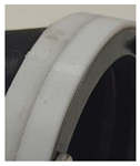
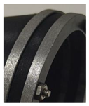
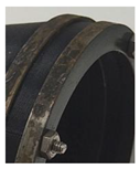
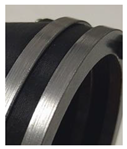
The types of yokes for validation in this study are shown below. The main features and appearances of the yokes are shown in Table 2.
(A)
Yokes with no processing
Yoke A has had no processing after being made on a lathe. The surface is very smooth and has no irregularities.
(B)
Yokes with rubber tires
Yoke B has tires with 1 mm thickness on Yoke A. The tires were made of TPU and made sufficiently flexible. The tires were fixed to the surface of the yokes by using thin double-sided tape to prevent shifting.
(C)
Yokes with axial grooves on the surface
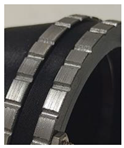
Yoke C has axial grooves on its surface, which is in contrast to Yoke A. There are 36 grooves equally spaced in a row. All of the grooves are 1 mm wide and of a 0.5 mm depth. Due to the manufacturing process, this yoke could not be knurled on a lathe like the yokes in the previous studies. Therefore, this machining was carried out using a milling machine.
(D)
Yokes with a gritty surface
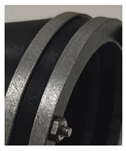
Yoke D has fine irregularities on its surface in contrast to Yoke A. These irregularities were created by hand using an electric file. This method was based on sandblasting, and the above process was carried out instead of using specialized equipment.
(E)
Yokes with corroded surfaces by sodium chloride solution
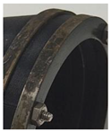
Yoke E has a corroded surface in contrast to Yoke A. The yoke was completely submerged in sodium chloride solution and left for about 24 h. After that, the yokes were removed from the brine, wiped, and dried thoroughly in the air. To ensure efficient corrosion, the concentration of the solution is 3%, which has the highest corrosion rate [17]. All of the processes for corrosion took place at room temperature at approximately 26 °C. This method was inspired by the fact that in previous research, rusted old wheels were less slippery and easier to drive on three-dimensional paths than new wheels.

2.3. Roughness of Yokes

It is expected that the differences in the surface conditions of the yokes will be important factors affecting the performance of adhesion and friction. However, accurate measurements of surface roughness are difficult, as they require specialized measuring equipment. In addition, macroscopic irregularities, such as that of Yoke C, are difficult to assess in the same league as typical surface roughness. Therefore, we devised an assessment of the surface condition of the yokes by applying the ‘frottage’ method. This is a method of visualizing or recording irregularity by rubbing a pencil on a paper covered with objects and is often used to record stone monuments or reliefs. Although it is less accurate, it can be used sufficiently to visualize the surface conditions of machine parts [18]. Therefore, it was used in this study.
Table 3 shows the surface conditions of the yokes visualized by the frottage method. The patterns on the yokes were copied on tracing paper by rubbing with a pencil. The paper was scanned, and the contrast was adjusted for better visibility.
Yoke A has no noticeable irregularities on the surface, and the four lines on the edges are highlighted. Machining marks from a lathe can also be seen as very thin white lines that are parallel to the edge. In Yoke B, areas with sudden changes in the thickness of the tires, including the edges and a dividing line in the center, are highlighted as lines. Yoke C’s equally spaced grooves have been clearly visualized. The grooves are represented as lines of approximately the same density as the edges. Due to the fine surface irregularities in Yoke D, the edge lines are relatively more blurred than in the other yokes. In addition, the machining marks cannot be seen. The shape of the irregularities itself is difficult to discern and is similar to the pattern for Yoke A. In Yoke E, it can be found that the irregularities are represented as a sparse pattern with the same density as the edge lines.

2.4. Experimental Apparatus

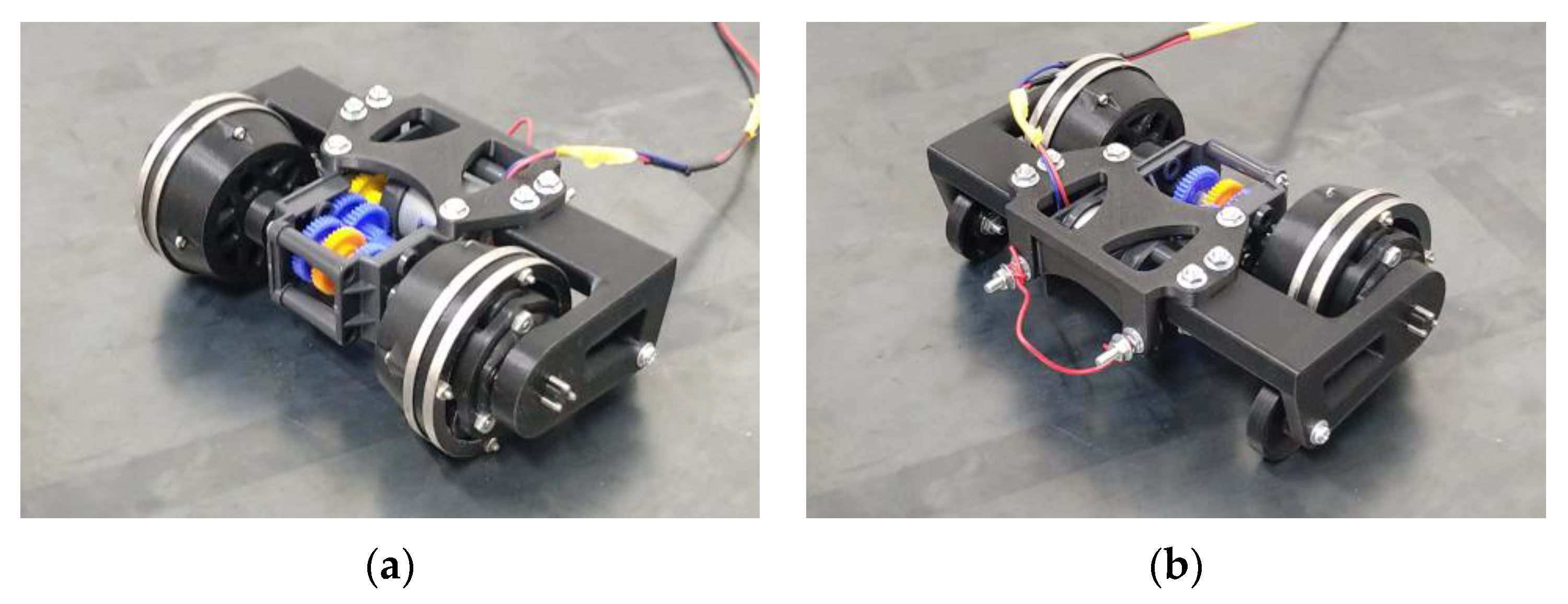
To investigate the frictional performance of the wheels during running, a towing robot, as shown in Figure 6, has been made. The robot moves forward by driving two PGMWs. On the rear of the robot, two auxiliary wheels with bearings rotate smoothly. A geared motor in the center of the robot drives the left and right PGMWs to move forward with a single output shaft. The rear of the robot can be connected to a force gauge to measure the traction force. Resistance from auxiliary wheels or air is negligible because the running speed is slow. This means that if the path is horizontal, the traction force of the robot is equal to the frictional force of the wheels.
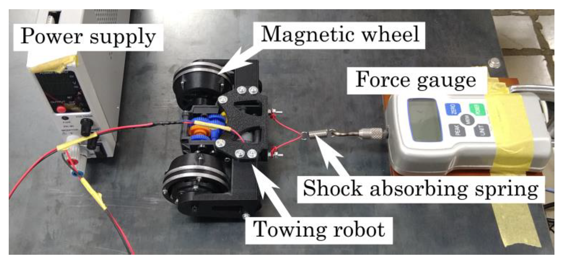
The experimental apparatus using the robot described above is shown in Figure 7. This apparatus measures the traction force of the robot running on a horizontal structure. The structure consists of a concrete panel with attached SS400 plates of 1.6 mm thickness. The surface of the structure has no painting, coating, or uneven texture. A force gauge is fixed to the structure behind the robot. A tensile spring for shock-absorbing is connected between the robot and the force gauge. When the robot moves forward, the force gauge can measure the traction force (friction force of the two wheels).

2.5. Experimental Procedures

The experimental procedures are shown below. All of the experiments were conducted at room temperature of approximately 26 °C.
  • The load on the front two wheels is measured according to the mass of the robot. The average of the three time measurements is used as the results.
  • The attractive force of one wheel with the magnets is measured. When the wheel attached to the steel structure is pulled up quietly in a vertical direction, the maximum force required for it to be pulled off the structure is the magnetic attractive force of the wheel. The average of the ten time measurements with the force gauge is used as the results.
  • The robot starts driving from a position in which the spring is loose. Eventually, the spring is stretched, and the robot cannot move forward due to the wheels slipping. The maximum traction force is taken as the “static traction force”. The average of the three time measurements is used as the results.
  • The robot is directly connected to a force gauge without the spring. The traction force when the robot is driving with slipping the wheels for about 10 s is taken as “the dynamic traction force”. The average of the three time measurements is taken as the result.
  • As shown above, Steps 1 to 4 are carried out with different types of yokes and with and without magnets. Afterward, all of the results are compared.

3. Results

The results of the experiments are shown below. Table 4 shows the experimental results without magnets in the wheels. Table 5 shows the experimental results with magnets in the wheels.
The normal forces on the wheels with magnets are much stronger than those without magnets. Therefore, to obtain accurate coefficients of friction, it is preferable to use the normal forces and the traction forces when the magnets are present. The normal forces and the coefficients of friction can be calculated by using the following equations, respectively.
N 2 w = W 2 w g + 2 M 1 w
μ j = T j N 2 w     ( j = S ,   D )
Furthermore, the coefficient reduction rate E μ is introduced. This value indicates how much the dynamic friction coefficient decreases from the static friction coefficient. In other words, if this value is high, it means that the traction force is likely to be lost due to the slipping of the wheels. This value can be calculated using the following Equation (3):
E μ = μ S μ D μ S × 100
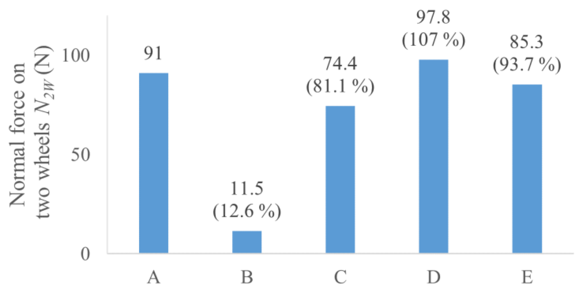
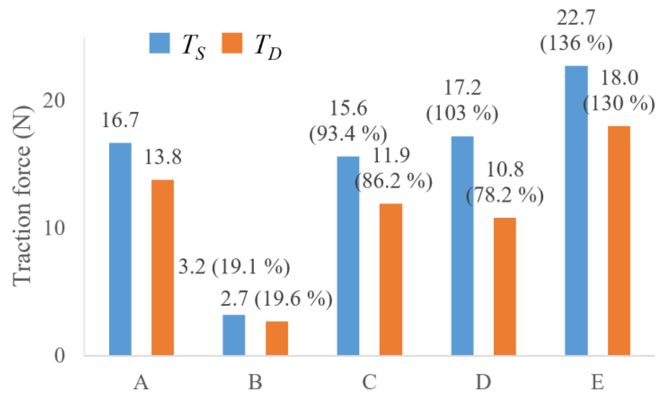
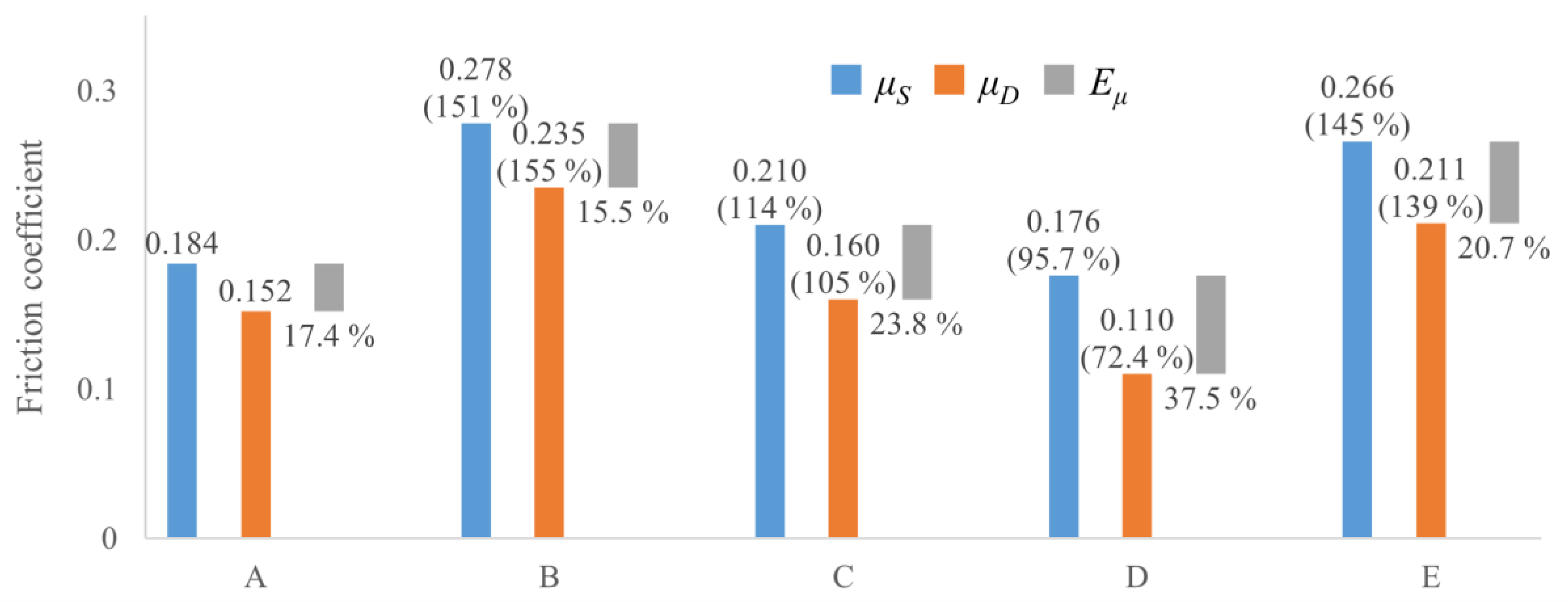
Figure 8, Figure 9 and Figure 10 shown below compare the performance calculated by using the data when the magnets are present.

3.1. Yoke A

Without magnets, the traction force was 0.3 N for both T S and T D . With magnets, T D was 13.8 N, which was less than T S = 16.7 N. When the friction coefficients were determined using the normal force and the traction force of the wheels with magnets, the static friction coefficient was 0.184, and the dynamic friction coefficient was 0.152. As a side note, these values are coincidentally similar to the coefficients of adhesion between the wheels and rails in Stockholm Public Transport, which are 0.18 for traction and 0.15 for braking [19]. Therefore, these experimental results are considered reasonable as the wheel’s performance is metal-to-metal contact.
The performances of the other yokes will be compared in the following sections with reference to Yoke A.

3.2. Yoke B to E without the Magnets

The normal forces on the wheels without magnets are due to the mass of the robot. This is approximately 250 g for all yokes. In this situation, Yokes B and E improved their traction forces. As the magnetic force was irrelevant, the reason for the increased traction forces of Yokes B and E can be attributed to the increased friction coefficient of the yoke itself.
Yoke D also improved the static traction force. However, this improvement was unclear in Yokes B and E due to the weaker normal force. Although typical materials in a dynamic state should have a smaller friction coefficient than in a static state, Yokes A and C have no difference in the coefficients between the dynamic and static. This means that the normal force of the wheels without magnets is insufficient to compare small changes in the performance.

3.3. Yoke B to E with the Magnets

This section briefly discusses the changing performances in each of the yokes from Yoke A.
Yoke B: The normal force decreased significantly from that of Yoke A. For both static and dynamic conditions, the traction force was the weakest among the yokes. On the other hand, friction coefficients increased and were the highest among the yokes. The coefficient reduction rate was the lowest.
Yoke C: The normal force decreased to 81.8% of Yoke A. On the other hand, the static and dynamic traction forces were 93.4% and 86.2%, respectively. The friction coefficient increased slightly to 114% and 105%.
Yoke D: The normal force improved to 107% of Yoke A. The static traction force increased, and the dynamic traction force decreased. This change was the same for the coefficients of friction. The coefficient reduction rate was the highest among the yokes.
Yoke E: The normal force decreased to 93% of A. However, the static and dynamic traction forces improved. The friction coefficients in static and dynamic conditions were also significantly improved.

4. Consideration

This chapter discusses the reason for the results obtained and examines the important factors to improve the performance of the yoke.

4.1. Yokes with Rubber Tires

The rubber tires on Yoke B significantly improved the friction coefficient. However, there was a critical problem: a significant reduction in the attractive force. As a result, the traction force was also greatly reduced.
Fabien Tache et al. tested the attractive forces on several magnetic wheels with rubber tires [20]. The experiments showed that in all cases, the attractive forces decreased approximately quadratically as the tires became thicker. However, these changes were gradual, and it is unlikely that tires with 1 mm thickness (about 2% of the wheel diameter) would cause a loss of 90% of the attractive force. It can be said that the attractive force of the PGMW is severely reduced by tires or some non-magnetic materials compared to their common magnetic wheels.

4.2. Yokes with Irregularity on the Surface

Both Yokes C and D have an uneven surface to improve the friction coefficient. Yoke C has relatively rough irregularities, whereas Yoke D has very fine irregularities. This processing produced different changes with respect to Yoke A. For traction force in static conditions, Yoke D was superior to Yoke C. According to the reduced friction coefficient, it seems that increasing the attractive force of Yoke D was the main reason for the results. However, when the wheel slipped, Yoke C exerted a stronger traction force than D. The friction coefficients increased for Yoke C and decreased for Yoke D in both static and dynamic conditions. The coefficient reduction rates were larger for Yoke D than for C.
Large irregularities, as seen in Yoke C, are used on metal tools or the running gears of vehicles. The main reason why these can increase friction and traction forces is that the many small protrusions make contact with the soft material (human skin or ground) on the other side. Such effects should be difficult for hard materials with smooth surfaces. Therefore, the specific reason why Yoke C was able to increase the friction coefficient on the steel is unknown. On the other hand, fine irregularities like Yoke D are used in the wheels of railway vehicles, as described in the introduction. However, these irregularities can be easily lost due to vehicle acceleration, deceleration, braking, or dirt between the wheels and rails. It is a common practice to maintain the surface roughness of the wheels by using a tread cleaning system. In the present experiment, no such device was implemented on the robot, and the fine irregularities were lost when the wheels slipped (dynamic conditions). This could be the reason why the dynamic traction force of Yoke D is weak and the coefficient reduction rate is large. In addition, the results of this experiment cannot be a conclusion that the fine irregularities have the effect of increasing the friction coefficient.
Based on the above, the requirements for the method of making irregularities are considered. First, it is possible to improve the friction coefficient by applying a certain degree of irregularities to the surface. However, the large irregularities can reduce attractive force. On the other hand, small irregularities can maintain the attractive force, but they can be scraped off by slipping the wheels. Therefore, it seems that the ideal way for the yokes is to make irregularities that cannot be scraped off and do not reduce the magnetic force.

4.3. Yokes with Corroded Surfaces

With the corroded surfaces, Yoke E obtained the strongest traction forces in both static and dynamic conditions. This can be attributed to two reasons: the smaller reduction of attractive force and increasing the friction coefficient. It is also important that the coefficient reduction rate was smaller than that of Yokes C and D.
The relationship between metal rust and friction has been the subject of studies in recent years [21,22]. For example, high-strength bolts used in structures like bridges are sometimes intentionally given red rust as a treatment to make the joint surfaces less slippery. According to Japanese standards, this treatment ensures the required slip coefficient (mechanically equivalent to the friction coefficient) of 0.45 [23]. The research has also been carried out on the rust on railway vehicles. This rust can increase or decrease the friction coefficient of the wheels, depending on the thickness of the rust layer, the main components of the rust, and the ambient temperature and humidity. However, rust is not actively used on real-life railways because it causes problems such as increased noise and vibration, reduced energy efficiency, and interference with track circuits [24].
The experimental results of Yoke E are discussed. First, the reason why the attractive force is stronger than yokes B and C is considered. The iron rust generated by corrosion at room temperature mainly consists of Fe3O4 and FeOOH (type α, β, or γ) [25]. The rust layers containing Fe3O4, a ferromagnetic material, seem to be less likely to reduce the attractive force than completely non-magnetic materials. In addition, the rust layer can be judged to be very thin because the corrosion was not significant enough to cause deterioration of the base material, and the diameter hardly changed from Yoke A. Therefore, the reason why Yoke E was able to maintain its attractive force can be attributed to its thinness and composition of the rust layer. However, iron rust is essentially a mixture of various compounds and is usually considered to be paramagnetic. Therefore, it is considered that the thinness of the layer is mainly the reason for the composition.
The reasons for the high friction coefficient are considered. The rust layer on Yoke E has a slightly roughened surface. This rust layer did not appear to peel or scrape off after experiments in dynamic conditions. It was less worn than the irregularities of the Yoke D. In other words, the surface of the rust layer is an uneven surface that does not decrease the magnetic force and does not scrape off by slipping. This feature is the same as that described in Section 4.2 as ideal features of irregularities.
To verify the stability of Yoke E, additional running tests in dynamic conditions were carried out. Figure 11 shows the shifting of traction forces of Yoke E with magnets in dynamic conditions. Measurements of the traction forces of Yoke E with slipping for about 10 s were repeated 15 times. As a result, the traction forces were stable but slightly increased. The reasons for this are unknown as to why the tractions improved slowly and why they were stronger than the results in Section 3. However, this result means that Yoke E maintains high traction even when subjected to multiple extreme slips and can withstand the wear that occurs in the practical environments of the wheels.
The composition of the rust layer is also of interest here. The rust layer generated by sodium chloride solutions has a porous structure and is often dominated by Fe3O4 and β-FeOOH. This is due to the effect of Cl. However, they all exhibited lubricating effects and reduced the friction coefficient of the wheel [26,27]. On the other hand, γ-FeOOH, which tends to occur when the effect of Cl is weak, has the effect of increasing the friction coefficient [28]. In addition, when the main component of the rust layer is γ-FeOOH, it is more difficult to remove from the wheel than in the case of β-FeOOH [21]. As Yoke E was airdried after immersion, there is enough possibility that the γ-type has become dominant instead of the β-type due to repeated oxidation and reduction in the rust layer. Moreover, this assumption is consistent with the fact that the rust layer is less prone to wear.
The frictional performance of an object is the result of the interaction of various factors that increase or decrease the friction coefficient. The performance of Yoke E is also influenced by both the surface condition and the composition of the rust layer. According to the comparisons with Yokes C and D, it seems that the irregularity on the surface contributes more or less to increasing the friction coefficient. On the other hand, it is considered that the friction performance, which is better than the other yokes, is the result of the increase in γ-FeOOH and decrease in Fe3O4 and β-FeOOH.

5. Conclusions

In this study, five different types of yokes were tested, and their properties were compared to find a better method of improving the friction performance of magnetic wheels. As a result, the findings shown below have been obtained:
  • The PGMWs tend to reduce the attractive force more than standard magnetic wheels when a non-magnetic material is between the yoke and the running surface. Therefore, designs that cover the yoke with rubber tires are not suitable for the PGMWs.
  • Rough irregularities of the yoke can improve the friction coefficient, but it reduces the attractive force.
  • Fine irregularities on the yoke do not reduce (or can improve) the attractive force. However, it is difficult to keep improving the friction coefficient. This is because the fine irregularities are scraped off by slipping.
  • Yoke E, which was corroded by sodium chloride solution, can improve the friction coefficient without a reduction in attractive force.
  • The reason why Yoke E did not impair the attractive force is because the rust layer is very thin and contains the ferromagnetic Fe3O4. However, the influence of the former is thought to be more dominant than the latter.
  • The main reason why Yoke E’s improved friction coefficient is thought to be that the rust layer has moderate irregularities on the surface and is not easily scraped off.
This study shows that covering the yoke with rust can be the most suitable method to ensure the friction coefficient of the magnetic wheels. Until now, rust has been a practical problem for machines such as railway vehicles and has been studied accordingly to deal with it. However, magnetic wheels, which require consideration of both friction performance and magnetic attraction force, can use rust effectively as a means of solving multiple problems. In addition, there are unique advantages to rust, such as the fact that it can be regenerated in an easy way, even if it wears out after long periods of use.
On the other hand, this research had not yet identified the structure of rust and the method of its formation that can have the best effect. In another study, it had also been noted that rust reduces the friction coefficient under certain conditions [26,27,28]. Therefore, a subject for future research is finding better methods within the approach of corroding.

Author Contributions

Conceptualization, M.T.; data curation, M.T.; format analysis, Y.T.; funding acquisition, T.S.; methodology, M.T.; project administration, Y.T.; supervision, Y.T.; validation, M.T. and K.O.; investigation, M.T.; writing—original draft preparation, M.T.; writing—review and editing, M.T., K.O., T.S. and Y.T. All authors have read and agreed to the published version of the manuscript.

Funding

This research received no external funding.

Data Availability Statement

Data are contained within the article.

Conflicts of Interest

Author Takehiro Shiba was employed by Measurement Industry Co., Ltd. The remaining authors declare that the research was conducted in the absence of any commercial or financial relationships that could be construed as a potential conflict of interest.

References

  1. Hao, S. I-35W Bridge Collapse. J. Bridge Eng. 2010, 15, 608–614. [Google Scholar] [CrossRef]
  2. Salem, H.M.; Hemley, H.M. Numerical investigation of collapse of the Minnesota I-35 bridge. Eng. Struct. 2014, 59, 635–645. [Google Scholar] [CrossRef]
  3. Ham, Y.; Han, K.K.; Lin, J.J.; Golparvar-Fard, M. Visual monitoring of civil infrastructure systems via camera-equipped Unmanned Aerial Vehicles (UAVs): A review of related works. Vis. Eng. 2016, 4, 1. [Google Scholar] [CrossRef]
  4. Almadhoun, R.; Taha, T.; Seneviratne, L.; Dias, J.; Cai, G. A survey on inspecting structures using robotic systems. Int. J. Adv. Robot. Syst. 2016, 13, 6. [Google Scholar] [CrossRef]
  5. Halder, S.; Afsari, K. Robots in Inspection and Monitoring of Buildings and Infrastructure: A Systematic Review. Appl. Sci. 2023, 13, 2304. [Google Scholar] [CrossRef]
  6. Hajjaj, S.S.H.; Khalid, I.B. Design and Development of an Inspection Robot for Oil and Gas Applications. Int. J. Eng. Technol. 2018, 7, 5–10. [Google Scholar] [CrossRef]
  7. Wang, R.; Kawahara, Y. An Automated Sensing System for Steel Bridge Inspection Using GMR Sensor Array and Magnetic Wheels of Climbing Robot. J. Sens. 2016, 2016, 16. [Google Scholar] [CrossRef]
  8. Nguyen, S.T.; Nguyen, H.; Bui, S.T.; Ho, V.A.; Ngo, T.D.; La, H.M. An Agile Bicycle-like Robot for Complex Steel Structure Inspection. In Proceedings of the International Conference on Robotics and Automation (ICRA), Philadelphia, PA, USA, 23–27 May 2022; pp. 157–163. [Google Scholar] [CrossRef]
  9. Noh, M.; Kwon, E.; Park, S.H.; Park, Y.W. Modeling of Attractive Force by Magnetic Wheel Used for Mobile Robot. Actuators 2020, 9, 67. [Google Scholar] [CrossRef]
  10. Zhu, J.; Zhu, Y.; Zhang, P. Review of Advancements in Wall Climbing Robot Techniques. Frankl. Open 2024, 8, 100148. [Google Scholar] [CrossRef]
  11. Tanida, M.; Ono, K.; Kobayashi, S.; Shiba, T.; Takada, Y. Study of Magnetic Wheels with Planetary Gears Which Make Running on Flange Paths Easy for Magnetic Wheeled Robot. J. Robot. Soc. Jpn. 2024, 42, 64–73. [Google Scholar] [CrossRef]
  12. Tanida, M.; Ono, K.; Shiba, T.; Takada, Y. Necessary Conditions for Running through a Flange by Using Planetary-Geared Magnetic Wheels. Robotics 2024, 13, 72. [Google Scholar] [CrossRef]
  13. Bisht, R.S.; Pathak, P.M.; Panigrahi, S.K. Experimental investigations on permanent magnet based wheel mechanism for safe navigation of climbing robot. Procedia Comput. Sci. 2018, 133, 377–384. [Google Scholar] [CrossRef]
  14. Skipper, W.A.; Chalsey, A.; Lewis, R. A review of railway sanding system research: Adhesion restoration and leaf layer removal. Tribol. Mater. Surf. Interfaces 2018, 12, 237–251. [Google Scholar] [CrossRef]
  15. Hanada, K.; Ikeuchi, K.; Saga, S. Development of Improved Wheel Friction Block with Integrated Flange Lubrication and Tread Adhesion Functions. Q. Rep. RTRI 2021, 62, 197–200. [Google Scholar] [CrossRef]
  16. Spiryagin, M.; Sun, Y.Q.; Cole, C.; Simson, S.; Persson, I. Ingemar PERSSON, Development of Traction Control for Hauling Locomotives. J. Syst. Des. Dyn. 2011, 5, 1214–1225. [Google Scholar] [CrossRef]
  17. Revie, R.W.; Uhlig, H.H. Corrosion and Corrosion Control; John Wiley & Sons: Hoboken, NJ, USA, 2008; p. 132. [Google Scholar] [CrossRef]
  18. Katori, K.; Okakura, T.; Yamamoto, K. Study on Surface od Casting (II). J. Jpn. Foundrymen’s Soc. 1949, 21, 1–8. [Google Scholar] [CrossRef]
  19. Magel, E.E. A Survey of Wheel/Rail Friction; Federal Railroad Administration: Washington, DC, USA, 2017.
  20. Tâche, F.; Fischer, W.; Caprari, G.; Siegwart, R.; Moser, R.; Mondada, F. Magnebike: A magnetic wheeled robot with high mobility for inspecting complex-shaped structures. J. Field Robot. 2009, 26, 453–476. [Google Scholar] [CrossRef]
  21. Zhu, Y. The influence of iron oxides on wheel–rail contact: A literature review. Proc. Inst. Mech. Eng. Part F J. Rail Rapid Transit 2018, 232, 734–743. [Google Scholar] [CrossRef]
  22. Xu, W.; Zhang, B.; Deng, Y.; Wang, Z.; Jiang, Q.; Yang, L.; Zhang, J. Corrosion of rail tracks and their protection. Corros. Rev. 2021, 39, 1–13. [Google Scholar] [CrossRef]
  23. Ministry of Land, Infrastructure, Transport and Tourism. Standard Specifications for Public Building Works (Building Construction). Available online: https://www.mlit.go.jp/common/001473539.pdf (accessed on 22 August 2024).
  24. Ban, T. Phenomena caused by substances intervening between the wheel and the rail. RRR 2008, 65, 10–13. [Google Scholar]
  25. Misawa, T. Corrosion Morphologies and Products of Iron and Steels in Wet Corrosion. Bull. Jpn. Inst. Met. 1985, 24, 201–210. [Google Scholar] [CrossRef]
  26. Zhu, Y.; Olofsson, U.; Chen, H. Friction Between Wheel and Rail: A Pin-On-Disc Study of Environmental Conditions and Iron Oxides. Tribol. Lett. 2013, 52, 327–339. [Google Scholar] [CrossRef]
  27. Nakahara, T.; Baek, K.S.; Chen, H.; Ishida, M. Relationship between surface oxide layer and transient traction characteristics for two steel rollers under unlubricated and water lubricated conditions. Wear 2011, 271, 25–31. [Google Scholar] [CrossRef]
  28. Chen, H.; Sone, Y.; Baek, K.S.; Nakahara, T.; Ishida, M. A Fundamental Study on Effect of Rust upon Adhesion Coefficient between Wheel and Rail. Rtri Rep. 2007, 21, 5–10. [Google Scholar]
Figure 1. A planetary geared magnetic wheel (PGMW). (a) Front view. (b) Rear view.
Robotics 13 00151 g001
Figure 2. Inside of the PGMW.
Robotics 13 00151 g002
Figure 3. SCPREM-I. (a) Front left view. (b) Running through a flange path.
Robotics 13 00151 g003
Figure 4. The magnetic circuit formed in the PGMW.
Robotics 13 00151 g004
Figure 5. A newly designed PGMW.
Robotics 13 00151 g005
Figure 6. A towing robot. (a) Front left view. (b) Rear right view.
Robotics 13 00151 g006
Figure 7. Experimental apparatus.
Robotics 13 00151 g007
Figure 8. A bar chart showing normal force on the yokes’ two wheels with magnets N 2 W . Parenthetic percentage figures on the chart are rates with Yoke A as 100%.
Robotics 13 00151 g008
Figure 9. A bar chart showing the traction forces of the towing robot with magnets. Blue bars show static condition T S . Orange bars show dynamic condition T D . Parenthetic percentage figures on the chart are rates with Yoke A as 100%.
Robotics 13 00151 g009
Figure 10. A bar chart showing the yokes’ friction coefficients. The blue bars show the coefficients in a static condition μ S . The orange bars show the coefficients in dynamic condition μ D . Gray bars show the reduction rate of the coefficient E μ . The parenthetic percentage figures are the rates with Yoke A as 100%.
Robotics 13 00151 g010
Figure 11. Shifting of traction forces of Yoke E with magnets in dynamic conditions.
Robotics 13 00151 g011
Table 1. Specifications of the PGMW with unprocessed yoke.
ParameterValue
Diameter of yokes53 mm
Inner diameter44 mm
Thickness of one yoke3.2 mm
Distance between two yokes3.6 mm
Shape of magnets 10   m m × ϕ 14   m m
Numbers of magnets3
Table 2. Varieties of yoke.
NameFeatureMass of a WheelAppearance
Without MagnetWith Magnet
AYokes with no processing75.3 g105.5 gRobotics 13 00151 i001
BYokes with using thin rubber tires77.8 g107.9 gRobotics 13 00151 i002
CYokes with axial grooves on the surface74.6 g104.7 gRobotics 13 00151 i003
DYokes with a gritty surface75.8 g105.8 gRobotics 13 00151 i004
EYokes with corroded surface by sodium chloride solution75.9 g106.1 gRobotics 13 00151 i005
Table 3. The surface condition of the yokes visualized by the frottage method.
Name Pattern
No AdjustmentAdjusted
ARobotics 13 00151 i006Robotics 13 00151 i007Robotics 13 00151 i008
BRobotics 13 00151 i009Robotics 13 00151 i010Robotics 13 00151 i011
CRobotics 13 00151 i012Robotics 13 00151 i013Robotics 13 00151 i014
DRobotics 13 00151 i015Robotics 13 00151 i016Robotics 13 00151 i017
ERobotics 13 00151 i018Robotics 13 00151 i019Robotics 13 00151 i020
Table 4. Experimental results without magnets.
NameLoad Applied on the Front Two WheelsTraction Force
StaticDynamic
W 2 w T S T D
A187.6 g0.3 N0.3 N
B187.1 g0.6 N0.6 N
C185.3 g0.3 N0.3 N
D185.3 g0.4 N0.3 N
E186.4 g0.6 N0.5 N
Table 5. Experimental results with magnets.
NameLoad Applied on the Front Two WheelsAttractive Force in One WheelTraction Force
StaticDynamic
W 2 w M 1 w T S T D
A242.7 g44.3 N16.7 N13.8 N
B255.3 g4.5 N3.2 N2.7 N
C241.2 g36.0 N15.6 N11.9 N
D247.2 g47.7 N17.2 N10.8 N
E255.0 g41.4 N22.7 N18.0 N
Disclaimer/Publisher’s Note: The statements, opinions and data contained in all publications are solely those of the individual author(s) and contributor(s) and not of MDPI and/or the editor(s). MDPI and/or the editor(s) disclaim responsibility for any injury to people or property resulting from any ideas, methods, instructions or products referred to in the content.