Abstract
This article proposes a mobile robot that is fully constructed and actuated by utilising a pneumatic artificial muscle (PAM). Several features are shown in this design including softness, lightweight, and shape change. The robot that has been designed in this article is constructed with four identical contraction actuators: one pair for steering and moving forward and the second pair for shape-shifting. The proposed mobile robot has the ability to move forward, steer, and shapeshift to navigate through narrow paths. The kinematic for the system is provided for the area of the robot by using the shoelace formula by utilising a Pixy camera to track the coordinates of the four vertices.
1. Introduction
Currently, robots are utilised everywhere in our social life, and industry is not the only workplace for these machines. Several types of robots are used, including traditional rigid robot arms, mobile robots, and medical (surgery and rehabilitation) robots. Most mobile machines are designed and constructed using rigid materials, and actuated by a type of electrical motor (DC, Servo, …, etc.) [1,2,3]. Because of the Corona pandemic, mobile robots have recently been increasingly frequently used to reduce direct contact between users [4,5].
The mobile robot can be designed as a legged, wheeled, snake, worm, spherical, and hybrid model [6,7,8,9]. Each type of robot moving technique has several advantages and limitations. The main feature of the wheeled mobile robots is the high velocity [10,11], while both snake and worm robots are considered more suitable for narrow paths [12]. A smooth floor is the main work area for spherical robots [13,14]. A hybrid mobile robot of course provides at least two different positives. On the other hand, each type shows limitations either because of the way it moves or the environment the robot serves. Furthermore, most moving robots suffer from the limitation of power supply [15].
Robots that have been made of rigid materials are heavy, unsafe for individuals, expensive, require a wide workspace, and they do not have the ability to adapt to the environment [11,16,17]. Applications can be selected for each type of moving robot depending on the structure, materials, and environment. The mobile robot is designed for investigation by [18,19] by embedding several sensors. While the investigation and monitoring are widely utilised applications [19,20,21,22], several challenges face the researchers such as obstacle avoidance [23,24], path planning [17,25], localisation strategies [16,26], and the lack of adaptation at the narrow paths.
In order to enhance the structure and the behaviour of the mobile robots, soft actuators are suggested in this article to build the full body of the robot and actuate it. The pneumatic artificial muscle (PAM) has been widely used recently to design and motivate numerous robot arms and grippers [8,27,28,29]. These soft actuators and soft robotics have shown another aspect of robotics, namely lightweight, inexpensive, flexible, easy to implement, and safe for individuals [30,31,32]. On the other hand, robots that have been made of silicon, dielectric elastomer, polyvinylidene fluoride, and paper can show high flexibility and deformation [9,33,34,35].
In this article, a soft square shape mobile robot is proposed with the ability to move, steer, and shrink to pass narrow paths. The robot is made by four identical contraction PAM. The proposed design provides a full soft robot body that can carry heavier objects than the robot itself due to the high weight ratio of the pneumatic muscles.
2. Pneumatic Artificial Muscle
The basic element in designing and implementing the soft mobile robot is the pneumatic artificial muscle. Figure 1 illustrates the schematic for the contraction PAM. The materials included in this design are the rubber tube, braided mesh, two solid ends, and fixing bands.
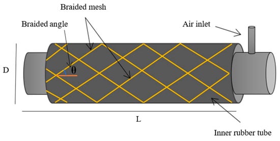
Figure 1.
The basic structure of the air soft actuator.
The air inlet allows the airflow in both directions to control the length of the PAM. The simple description for the behaviour of the contraction actuator is the shortness in length at the filling process, and that provides a tensile force depending on the dimensions and the contraction ratio [36].
Several experiments have been done to investigate the behaviour of the air actuator in terms of contraction and tensile force. The maximum contraction ratio for this system depends on several parameters, including the inner tube characteristics (see Table 1), the braided mesh dimensions, and its expandable ratio (Table 2). The diameter of the mesh expands by 46% and that limits the contraction ratio. Another factor that limits the contraction ratio is the braided angle θ (Figure 1) which also controls the behaviour of the actuator. The braided angle gives the contraction behaviour of the PAM if its value is less than 54.7° [8,37].

Table 1.
The initial Dimensions of the contraction PAM.

Table 2.
The parameters of the braided mesh.
To verify the contraction performance of the actuator, air pressure is applied by step of 50 kPa from zero to 500 kPa. Figure 2 illustrates the resulting length as a function of air pressure. Figure 3 shows the contraction ratio.

Figure 2.
The length of the actuator at various pressure values.
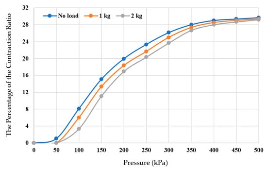
Figure 3.
The Contraction ratio of 30 cm PAM.
Figure 2 shows that the length of the actuator starts decreasing dramatically at about 50 kPa and it changes slowly at 400 kPa till 500 kPa at each load condition. The length difference is about 9 cm. The designed actuators have a contraction ratio greater than 100%, which is greater than that of the Festo MAS-10, which provides a 14% contraction ratio at 689 kPa [38].
The percentage of the contraction ratio in Figure 3 illustrates that the system stops contracting at 29.67% and the percentage is 29% at 400 kPa at different loads, and the load does not impact the contraction ratio at high pressure. From Figure 2 and Figure 3, the PAM reaches the maximum shortness at 400 kPa and the last 100 kPa does not add significant change. Therefore, the maximum operating air pressure is selected at 400 kPa for safe working and to decrease the probability of actuator damage.
On the other hand, another experiment is done to show the tensile force by fixing the PAM from the top and connecting the second side to a weight scale, as shown in Figure 4. The pressure is applied at step 50 kPa, and the force is recorded, as shown in Figure 5.
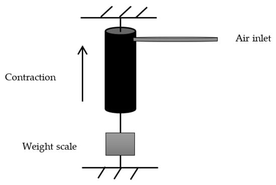
Figure 4.
The force experiment setup for the PAM.
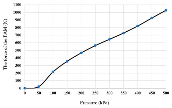
Figure 5.
The tensile force of the PAM.
Figure 5 illustrates that the manufactured PAM has a high power-to-weight ratio. The weight of the actuator is 0.38 kg, while the contraction force is about 104 kg, giving a ratio of 273.7. This powerful behaviour gives the robot the ability to move against gravity and friction. Compared to conventional actuators, shape memory alloys, rigid pneumatic cylinders, and electrical actuators, the PAM shows high performance in most of them [39,40].
3. Robot Design
The design idea is inspired by the dilation of quadrilaterals. Four contraction PAM of 30 cm is used to design the robot. It moves forward and steers, and has the ability to change its shape to pass through a narrow path.
3.1. Squeezed Mobile Robot
The mobile robot is built by using four contraction muscles each of 30 cm rest length. Figure 6 shows the design of the proposed robot. The dimensions of the mobile robot are shrinking by a maximum of 30% of its unpressurised values. The four caps are designed as a right-angle shape adding about 4 cm on each side and 4 cm for the L-shape angle. Therefore, the total side length is 46 cm. The maximum area of the robot is 2116 cm2, while the minimum area is 1369 cm2.
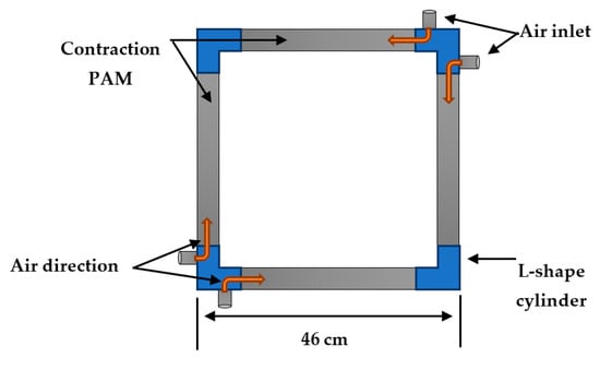
Figure 6.
the structure of the squeezed mobile robot.
Applying air pressure to the contraction PAM leads to shrinking its length from both sides towards the centre (see Figure 7). Since the desired movement for the proposed robot is forward, one of the ends need to be stationary at each time the movement started. The movement restriction follows the algorithm below for right and left PAMs.

Figure 7.
the contraction direction of the PAM.
The step distance d for both the 4 and 5 processes can be calculated according to (1) to (4).
or
and
or
where, L0 is the unpressurized length, L is the length of the actuator at any pressure, and ε is the contraction ratio. Figure 8 illustrates the moving process of the A4SMR at the filling and venting processes.
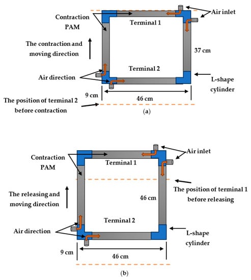
Figure 8.
the moving steps. (a) Terminal 2 moves forward by 9 cm. (b) Terminal 1 moves forward by 9 cm.
The dashed lines indicate the positions of terminal 1 and terminal 2. Figure 8a shows that the robot contracted by 9 cm from terminal 2 during the filling process, while Figure 8b shows that terminal 1 has been moved by 9 cm. As a result, the moving step for the whole robot’s body is moving by 9 cm.
To keep the robot moving forward only as described in Algorithm 1, unidirectional wheels need to use. In this article, the freewheel of 5 cm in diameter is used, as shown in Figure 9. The freewheel is designed primarily for use in bicycles.
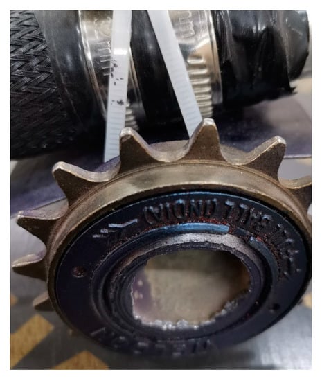
Figure 9.
The freewheel to obtain unidirectional moving.
| Algorithm 1. The movement restriction |
| 1: Take Figure 6 as a reference. 2: Set the top of the proposed robot as terminal 1. 3: Set the bottom of the Robot as terminal 2. 4: In the pressurising process, terminal 1 restricts, and terminal 2 keeps free to move. The rear of the robot moves forward due to contraction behaviour. 5: During the venting process, terminal 1 sets to free, and terminal 2 is restricted. The robot will move forward at a similar distance. 6: Repeat 4 and 5 to keep moving forward. |
The bicycle system has been greatly growing due to numerous applications not just for transportation. Several GYM equipment is a type of bicycle that has freewheel parts, and many health care devices include bicycle parts too [41,42].
The freewheel was created to move freely in one direction. This behaviour has been utilised in this article to maintain moving forward. The total weight of the whole robot body with the unidirectional wheels is the weight summation of four actuators (4 × 0.38 kg) and four freewheels (4 × 0.144 kg), which yields 2.096 kg.
3.2. Passing through Narrow Paths
The A4SMR offers a reduction in its width by a maximum of 9 cm to pass through paths that are less in width. Figure 10 shows the setup for the experiments. Practically, a Pixy Cam (Carnegie Mellon University, Create Lab, PA, USA) is used to track the coordinates of four different colour objects attached to the vertices. Pixy camera tracks width, height, and depth. The height (Z-axis) is ignored because the system moves in the x-y plane.

Figure 10.
The shape change process. (a) A4SMR is the wide path. (b) A4SMR is the narrow path.
Figure 10a illustrates the robot at a wide path. The A4SMR shows a zero contraction ratio for the right and left actuators. A single colour is used for both sides of the path. The Pixy cam detects the predefined colour, and, consequently, the system offers zero air pressure for side PAMs. On the other hand, Figure 10b shows shrinking in both side muscles at the narrow path for predefined colour. In this experiment, only two states are used: wide path (normal path) and single narrow track. Therefore, two tracking colours have been used. The PIXY cam has been designed to follow 7 different colours. In this article, six different colours are used.
The top and bottom soft actuators are not responsible for forwarding movements. Both are acting of steering and/or shape-changing. While each process includes the filling and venting, the robot will move by “d”. The time of maximum contraction is recorded as 1.62 s, while the release time is about 2.1 s, and the time stop between these operations is selected to be 1 s. Therefore, the total time for each step is 4.72 s. This gives a speed of 1.9 cm/s or 68.4 m/h. The pneumatic artificial muscles are considered slow actuators in contrast to other high performances.
The proposed robot shifts its shape by changing the length of each side individually or by a combination of two, three, or all of them simultaneously. The change in length depends on the amount of air pressure and the structure of the PAM [36]. Figure 11 Illustrates a photograph of the proposed soft mobile robot at zero pressure, and Figure 12 shows the A4SMR at 200 kPa on each side.
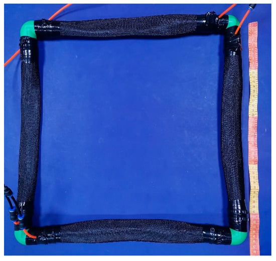
Figure 11.
The contraction type of the proposed shape-shift mobile robot.
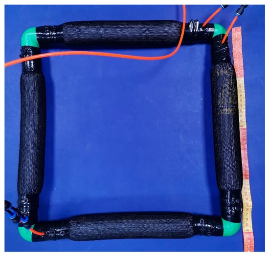
Figure 12.
The proposed shape-shift mobile robot at 200 kPa.
Various shapes are produced by the robot depending on the air pressure at each actuator. Figure 13 shows examples of possible forms.
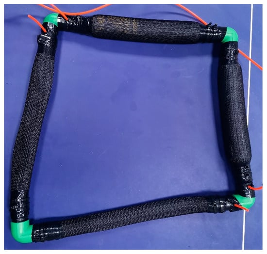
Figure 13.
Irregular quadrable robot form.
4. Robot Kinematics
Calculating the area for a certain shape is always possible in terms of mathematics. Due to the variety of the resulting shapes and irregular forms always possible, a general mathematical equation is needed. The Shoelace formula is used to calculate the area of the proposed robot by finding the 2D coordinates of all vertices [43,44,45]. The formula is given in (5).
For the proposed robot, the number of vertices is four, and if it is assumed that the centre of the robot is the origin give an example of the robot. Figure 14 shows the mobile soft robot shape at zero pressure.
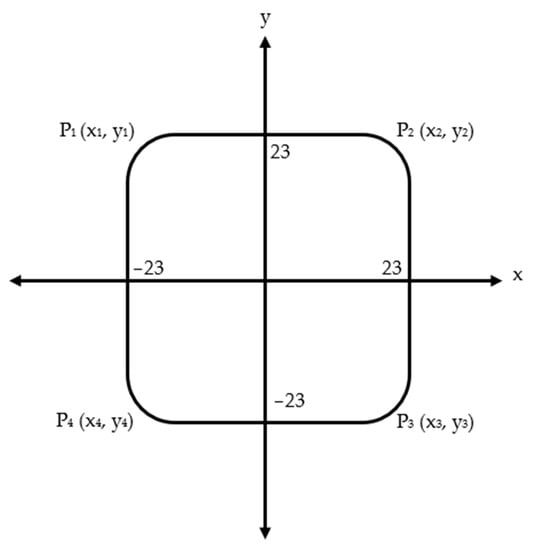
Figure 14.
The mobile robot shape at rest condition.
The coordinates of the vertices of Figure 13 can be written as follows:
(−23, 23), (23, 23), (23, −23), and (−23, −23) respectively. Therefore, the shoelace formula is:
After calculation, A = 2116 cm2. This area can be found directly by calculating the area of a square. This formula can calculate the area of the proposed robot whatever its form is.
In addition to the forward movement, the robot can steer right and left according to the pressure amount at side PAMs. While the maximum contraction for each actuator is 9 cm, the steering angle can be analysed as shown in Figure 15.
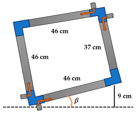
Figure 15.
The A4SMR at full contraction condition for the left actuator.
The maximum steering angle occurs at the maximum contraction ratio for one of the side actuators. As described in Algorithm 1, and because of the use of the unidirectional wheel, the actuator contracts by 9 cm from the rear. This operation leads to pulling and steering the whole robot body by βmax. The steering angle can be found in (7) and (8).
Lb is the length of the bottom actuator. Releasing the side actuator be venting the air pressure provides moving the actuator from the upper side and gives another β. As a result, the steering angle α is:
The maximum steering angle occurs at 9 cm contraction and the full length of the bottom actuator.
5. Test and Validation
Pixy camera offers seven tracking objects at a time. In this section, six different tracking colours are used. Four have been fixed to the vertices and two are used to determine the width of the path. The first experiment is executed by applying different air pressure for each muscle and then calculating the area of the robot by using the shoelace theorem and geometry. Table 3 lists the area of the robot at different coordinates after moving it forward at similar air pressure for the four actuators and applying different air pressure at various patterns.

Table 3.
The robot area at different coordinates.
Table 3 shows that the area calculated by the shoelace formula is quite similar to the area measured manually, especially for the regular shape robots. The four top rows are the coordinates for the rectangular forms, while the last row represents a trapezoidal.
The second experiment is undertaken to show the shrinking of the proposed robot. The Pixy camera indicates the path width by calculating the distance between the two colours and then setting the required length for the top and bottom actuators. The robot can pass through paths that are at least 38 cm in width.
6. Conclusions
The presented mobile robot can move and change its shape, mainly by contracting its width, according to the width of the tracks. Despite the slow movement of the robot, it offers the required flexibility and adaptability. This positive result can be added to the long list of advantages of soft robots and the PAM such as the low cost, ease of implementation, high force, lightweight, friend to the environment, safe for human-robot interaction, and ease of replacement. The maximum applied air pressure is 500 kPa to maintain the important safety of the workspace, and this gives a maximum contraction ratio of about 30%.
Because of the softness of the materials that have been used to design the A4SMR and the actuating by air, it can be used in a quiet environment. Therefore, it can be used for monitoring or, because of the high force of the PAM, carrying an object.
Author Contributions
Data curation, M.A.A.-I.; Formal analysis, F.K.A.-A. and A.A.-I.; Investigation, M.A.A.-I.; Methodology, M.A.A.-I., F.K.A.-A. and A.A.-I.; Software, A.A.-I.; Validation, A.A.-I.; Visualization, F.K.A.-A.; Writing—original draft, A.A.-I.; Writing—review & editing, M.A.A.-I. All authors have read and agreed to the published version of the manuscript.
Funding
This research received no external funding.
Institutional Review Board Statement
Not applicable.
Data Availability Statement
The datasets generated and/or analysed during the current study are available from the corresponding author on reasonable request.
Acknowledgments
The authors express their thanks to the Computer Engineering Department, the University of Basrah to provides the necessary lab to build and test the robot.
Conflicts of Interest
The authors declare no conflict of interest.
References
- Alves, R.M.F.; Lopes, C.R. Obstacle avoidance for mobile robots: A Hybrid Intelligent System based on Fuzzy Logic and Artificial Neural Network. In Proceedings of the 2016 IEEE International Conference on Fuzzy Systems (FUZZ-IEEE), Vancouver, BC, Canada, 24–29 July 2016; pp. 1038–1043. [Google Scholar] [CrossRef]
- Navabi, H.; Sadeghnejad, S.; Ramezani, S.; Baltes, J. Position control of the single spherical wheel mobile robot by using the fuzzy sliding mode controller. Adv. Fuzzy Syst. 2017, 2017, 2651976. [Google Scholar] [CrossRef]
- Shabalina, K.; Sagitov, A.; Magid, E. Comparative Analysis of Mobile Robot Wheels Design. In Proceedings of the 2018 11th International Conference on Developments in eSystems Engineering (DeSE), Cambridge, UK, 2–5 September 2018; pp. 175–179. [Google Scholar]
- Bačík, J.; Tkáč, P.; Hric, L.; Alexovič, S.; Kyslan, K.; Olexa, R.; Perduková, D. Phollower—The Universal Autonomous Mobile Robot for Industry and Civil Environments with COVID-19 Germicide Addon Meeting Safety Requirements. Appl. Sci. 2020, 10, 7682. [Google Scholar] [CrossRef]
- Maurelli, F.; Dineva, E.; Nabor, A.; Birk, A. Robotics and Intelligent Systems: A New Curriculum Development and Adaptations Needed in Coronavirus Times. In Robotics in Education; Springer: Berlin/Heidelberg, Germany, 2022; pp. 81–93. [Google Scholar]
- Guccione, S.; Muscato, G. The wheeleg robot—Control strategies, computing architectures, and experimental results of the hybrid wheeled/legged robot. IEEE Robot. Autom. Mag. 2003, 10, 33–43. [Google Scholar] [CrossRef]
- Carpentier, J.; Wieber, P.-B. Recent Progress in Legged Robots Locomotion Control. Curr. Robot. Rep. 2021, 2, 231–238. [Google Scholar] [CrossRef]
- Al-Ibadi, A.; Nefti-Meziani, S.; Davis, S. Design, Kinematics and Controlling a Novel Soft Robot Arm with Parallel Motion. Robotics 2018, 7, 19. [Google Scholar] [CrossRef]
- Tian, Y.; Yao, Y.-A.; Ding, W.; Xun, Z. Design and locomotion analysis of a novel deformable mobile robot with worm-like, self-crossing and rolling motion. Robot. 2016, 34, 1961–1978. [Google Scholar] [CrossRef]
- Khairullah, Y.; Marhoon, A.; Rashid, M.; Rashid, A. Multi Robot System Dynamics and Path Tracking. Iraqi J. Electr. Electron. Eng. 2020, 16, 1–7. [Google Scholar] [CrossRef]
- Zhang, L.; Liu, L.; Zhang, S. Design, Implementation, and Validation of Robust Fractional-Order PD Controller for Wheeled Mobile Robot Trajectory Tracking. Complex. 2020, 2020, 9523549. [Google Scholar] [CrossRef]
- Liu, J.; Tong, Y.; Liu, J. Review of snake robots in constrained environments. Rob. Auton. Syst. 2021, 141, 103785. [Google Scholar] [CrossRef]
- Bujňák, M.; Pirník, R.; Rástočný, K.; Janota, A.; Nemec, D.; Kuchár, P.; Tichý, T.; Łukasik, Z. Spherical Robots for Special Purposes: A Review on Current Possibilities. Sens. 2022, 22, 1413. [Google Scholar] [CrossRef]
- Chase, R.; Pandya, A. A Review of Active Mechanical Driving Principles of Spherical Robots. Robot. 2012, 1, 3–23. [Google Scholar] [CrossRef]
- Hou, L.; Zhang, L.; Kim, J. Energy Modeling and Power Measurement for Mobile Robots. Energ. 2018, 12, 27. [Google Scholar] [CrossRef]
- AL-Forati, I.S.A.; Rashid, A.; Al-Ibadi, A. IR Sensors Array for Robots Localization Using K Means Clustering Algorithm. Int. J. Simul. Syst. Sci. Technol. 2019, 20, 12. [Google Scholar] [CrossRef]
- Jiang, H.; Wang, H.; Yau, W.-Y.; Wan, K.-W. A Brief Survey: Deep Reinforcement Learning in Mobile Robot Navigation. In Proceedings of the 2020 15th IEEE Conference on Industrial Electronics and Applications (ICIEA), Kristiansand, Norway, 9–13 November 2020; IEEE; pp. 592–597. [Google Scholar]
- Jung, Y.H.; Cho, D.H.; Hong, J.W.; Han, S.H.; Cho, S.B.; Shin, D.Y.; Lim, E.T.; Kim, S.S. Development of Multi-Sensor Module Mounted Mobile Robot for Disaster Field Investigation. Int. Arch. Photogramm. Remote Sens. Spat. Inf. Sci. 2022, 43, 1103–1108. [Google Scholar] [CrossRef]
- Nalepa, B.; Gwiazda, A.; Banas, W. Investigation of movement of mobile robot work. IOP Conf. Ser. Mater. Sci. Eng. 2018, 400, 052007. [Google Scholar] [CrossRef]
- Rahmaniar, W.; Wicaksono, A. Design and Implementation of a Mobile Robot for Carbon Monoxide Monitoring. J. Robot. Control 2020, 2, 1–6. [Google Scholar] [CrossRef]
- Girdhar, Y.; Dudek, G. Modeling curiosity in a mobile robot for long-term autonomous exploration and monitoring. Auton. Robots 2016, 40, 1267–1278. [Google Scholar] [CrossRef]
- Sumiya, T.; Matsubara, Y.; Nakano, M.; Sugaya, M. A Mobile Robot for Fall Detection for Elderly-Care. Procedia Comput. Sci. 2015, 60, 870–880. [Google Scholar] [CrossRef]
- Rostami, S.M.H.; Sangaiah, A.K.; Wang, J.; Liu, X. Obstacle avoidance of mobile robots using modified artificial potential field algorithm. EURASIP J. Wirel. Commun. Netw. 2019, 2019, 70. [Google Scholar] [CrossRef]
- Hutabarat, D.; Rivai, M.; Purwanto, D.; Hutomo, H. Lidar-based Obstacle Avoidance for the Autonomous Mobile Robot. In Proceedings of the 2019 12th International Conference on Information & Communication Technology and System (ICTS), Surabaya, Indonesia, 18 July 2019; IEEE; pp. 197–202. [Google Scholar]
- Abdouni, J.; Jarou, T.; Waga, A.; El Idrissi, S.; El mahri, M.; Sefrioui, I. A new sampling strategy to improve the performance of mobile robot path planning algorithms. In Proceedings of the 2022 International Conference on Intelligent Systems and Computer Vision (ISCV), Fez, Morocco, 18–20 May 2022; IEEE; pp. 1–7. [Google Scholar]
- César-Tondreau, B.; Warnell, G.; Kochersberger, K.; Waytowich, N.R. Towards Fully Autonomous Negative Obstacle Traversal via Imitation Learning Based Control. Robotics 2022, 11, 67. [Google Scholar] [CrossRef]
- Liang, D.; Sun, N.; Wu, Y.; Chen, Y.; Fang, Y.; Liu, L. Energy-Based Motion Control for Pneumatic Artificial Muscle Actuated Robots with Experiments. IEEE Trans. Ind. Electron. 2022, 69, 7295–7306. [Google Scholar] [CrossRef]
- Wang, Q.; Liu, G.; Yang, T.; Chen, H.; Qin, Y.; Sun, N. Dynamic Modeling and Analysis for Parallel Robots Actuated by Pneumatic Artificial Muscles. In Control, Instrumentation and Mechatronics: Theory and Practice; Springer: Singapore, 2022; pp. 22–33. [Google Scholar]
- Al Abeach, L.A.T.; Nefti-Meziani, S.; Davis, S. Design of a Variable Stiffness Soft Dexterous Gripper. Soft Robot. 2017, 4, 274–284. [Google Scholar] [CrossRef] [PubMed]
- Al-Ibadi, A. The Design and Implementation of a Single-Actuator Soft Robot Arm for Lower Back Pain Reduction. Iraqi J. Electr. Electron. Eng. 2020, sceeer, 25–29. [Google Scholar] [CrossRef]
- Robinson, G.; Davies, J.B.C. Continuum robots—A state of the art. In Proceedings of the 1999 IEEE International Conference on Robotics and Automation (Cat. No.99CH36288C), Detroit, MI, USA, 10–15 May 1999; Volume 4, pp. 2849–2854. [Google Scholar]
- Shintake, J.; Cacucciolo, V.; Floreano, D.; Shea, H. Soft Robotic Grippers. Adv. Mater. 2018, 30, 1707035. [Google Scholar] [CrossRef]
- Kim, S.; Laschi, C.; Trimmer, B. Soft robotics: A bioinspired evolution in robotics. Trends Biotechnol. 2013, 31, 287–294. [Google Scholar] [CrossRef]
- Liu, Y.; Liu, L.; Sun, S.; Zhang, Z.; Leng, J. Stability analysis of dielectric elastomer film actuator. Sci. China Ser. E Technol. Sci. 2009, 52, 2715–2723. [Google Scholar] [CrossRef]
- Park, T.; Cha, Y. Soft mobile robot inspired by animal-like running motion. Sci. Rep. 2019, 9, 14700. [Google Scholar] [CrossRef] [PubMed]
- Al-Ibadi, A.; Nefti-Meziani, S.; Davis, S. Efficient Structure-Based Models for the McKibben Contraction Pneumatic Muscle Actuator: The Full Description of the Behaviour of the Contraction PMA. Actuators 2017, 6, 32. [Google Scholar] [CrossRef]
- Al-Fahaam, H.; Davis, S.; Nefti-Meziani, S. The design and mathematical modelling of novel extensor bending pneumatic artificial muscles (EBPAMs) for soft exoskeletons. Rob. Auton. Syst. 2018, 99, 63–74. [Google Scholar] [CrossRef]
- Aschenbeck, K.S.; Kern, N.I.; Bachmann, R.J.; Quinn, R.D. Design of a Quadruped Robot Driven by Air Muscles. In Proceedings of the The First IEEE/RAS-EMBS International Conference on Biomedical Robotics and Biomechatronics, Pisa, Italy, 20–22 February 2006; Volume 2006, pp. 875–880. [Google Scholar]
- Mavroidis, C.; Pfeiffer, C.; Mosley, M. Conventional Actuators, Shape Memory Alloys, and Electrorheological Fluids. Autom. Miniat. Robot. Sensors Non-Destructive Test. Eval. 1999, 1–26. Available online: http://engineering.nyu.edu/mechatronics/Control_Lab/bck/Padmini/Nano/Mavroidis/ch5-1-dinos-actuators3.pdf (accessed on 24 October 2022).
- Mavroidis, C. Development of Advanced Actuators Using Shape Memory Alloys and Electrorheological Fluids. Res. Nondestruct. Eval. 2002, 14, 1–32. [Google Scholar] [CrossRef]
- Hou, Y.C.; Su, S.H.; Tseng, C.H.; Fong, Z.H. An efficient optimum design procedure for bicycle rear derailleurs. Int. J. Veh. Des. 1996, 17, 483–503. [Google Scholar] [CrossRef]
- Lai, W.H.; Sung, C.K.; Wang, J.B. Motion analysis of a bicycle rear derailleur during the shifting process. Mech. Mach. Theory 1998, 33, 365–378. [Google Scholar] [CrossRef]
- Garza-Hume, C.E.; Jorge, M.C.; Olvera, A. Areas and Shapes of Planar Irregular Polygons. Forum Geom. 2018, 18, 17–36. [Google Scholar]
- Chaki, R.; Cortesi, A.; Saeed, K.; Chaki, N. Advanced Computing and Systems for Security; Springer: New Delhi, India, 2016; Volume 396, ISBN 9788132226512. [Google Scholar]
- Pure, R.; Durrani, S. Computing Exact Closed-Form Distance Distributions in Arbitrarily Shaped Polygons with Arbitrary Reference Point. Math. J. 2017, 17, 1–27. [Google Scholar] [CrossRef]
Publisher’s Note: MDPI stays neutral with regard to jurisdictional claims in published maps and institutional affiliations. |
© 2022 by the authors. Licensee MDPI, Basel, Switzerland. This article is an open access article distributed under the terms and conditions of the Creative Commons Attribution (CC BY) license (https://creativecommons.org/licenses/by/4.0/).