Tunable Vibration Absorber Design for a High-Precision Cartesian Robot
Abstract
:1. Introduction
2. CNC Robot
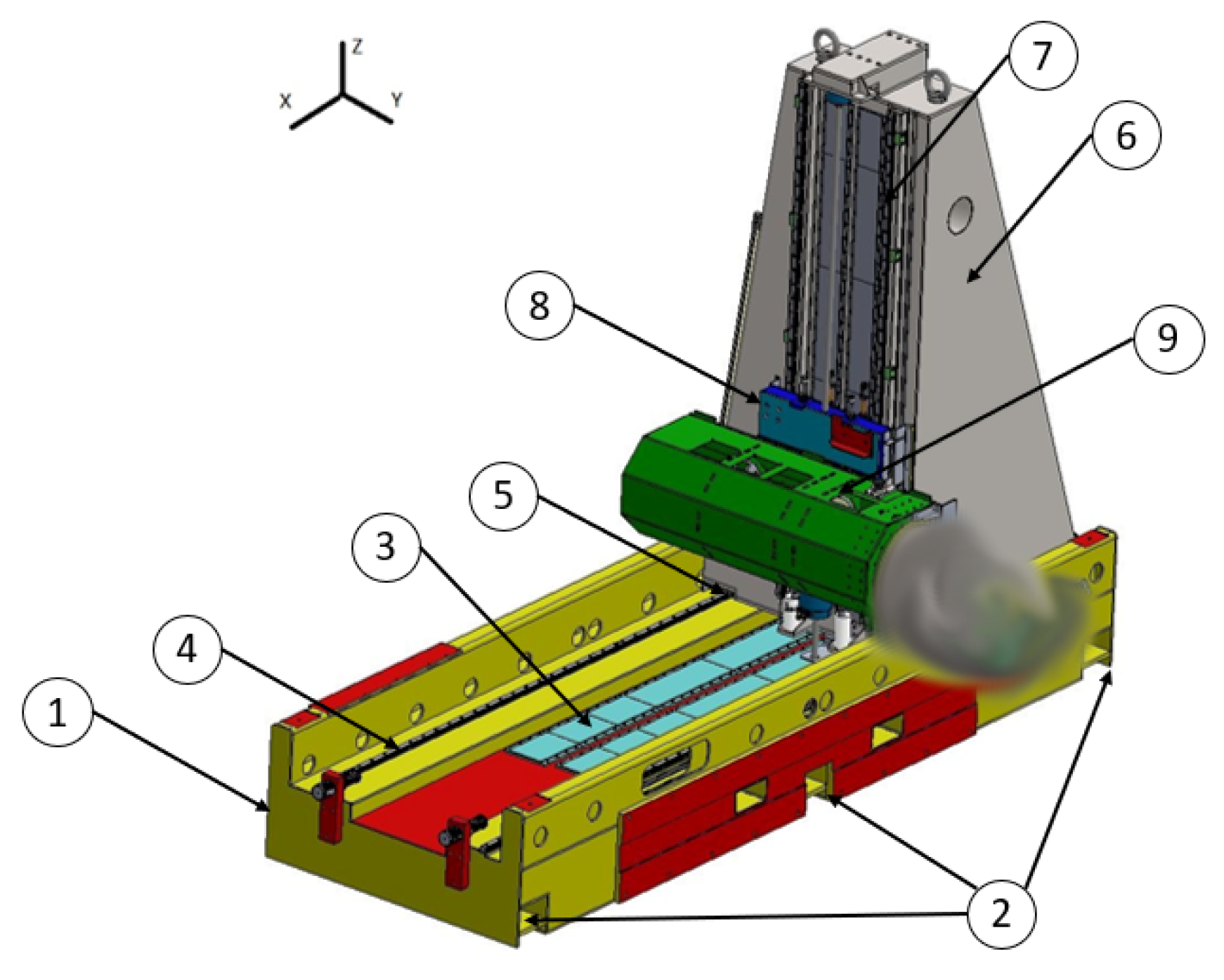
2.1. Robot Description
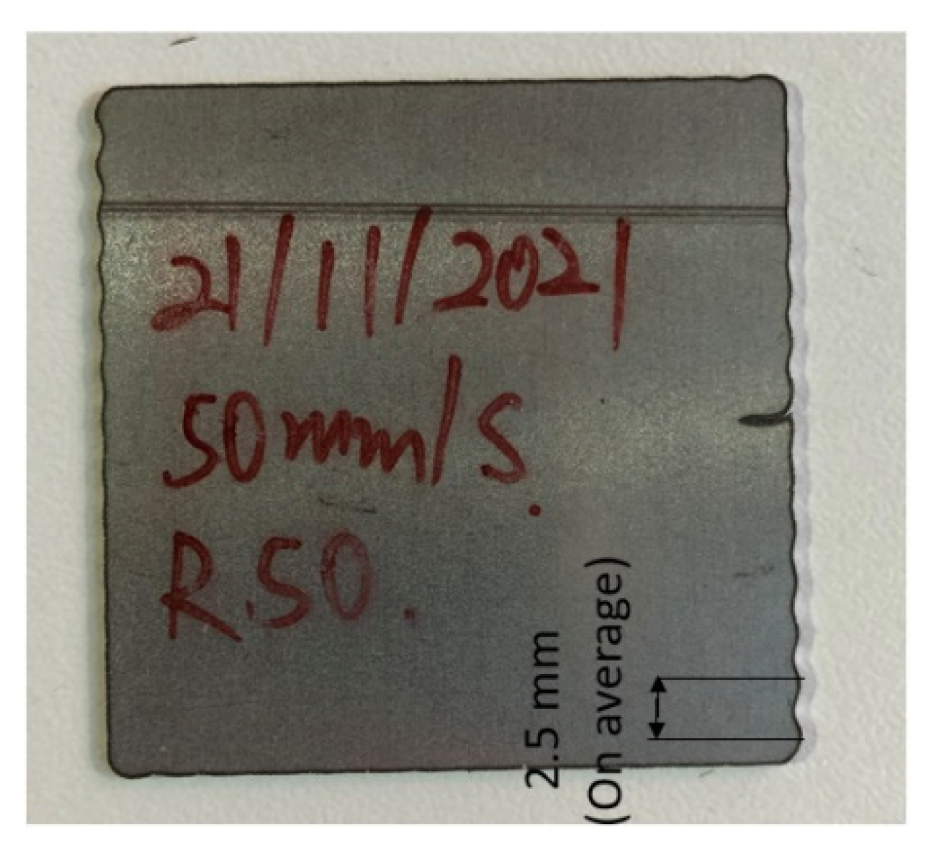
2.2. Cutting Test and Experimental Dynamic Evaluation
- As expected, the machine presents a resonant frequency shift between the most critical configuration, 20 Hz, and the least one, 24 Hz. This happens because the moment of inertia with respect to the constraint, i.e., the column base, reduces as the masses are closer to it.
- The 20 Hz frequency always shows a higher displacement with respect to the 24 Hz one, even though along the X direction, for each axis movement, the displacement difference is not remarkable. This may be because the oscillation along the X direction is a consequence of the column bending about the Y axis. The bending about the Y axis depends on the distance between the column constraint, i.e., the slide, and the center of mass position of the Y-Group along directions Z and X. When the Y-Group is at its stroke start, the distance between center of mass and slide reduces in the Z direction, thus inducing a change in frequency, but the distance between center of mass and slide along the X direction remains unchanged, thus keeping a relatively high oscillation amplitude.
2.3. Machine Modal and Frequency Response FEM Analysis
2.3.1. Modal Analysis
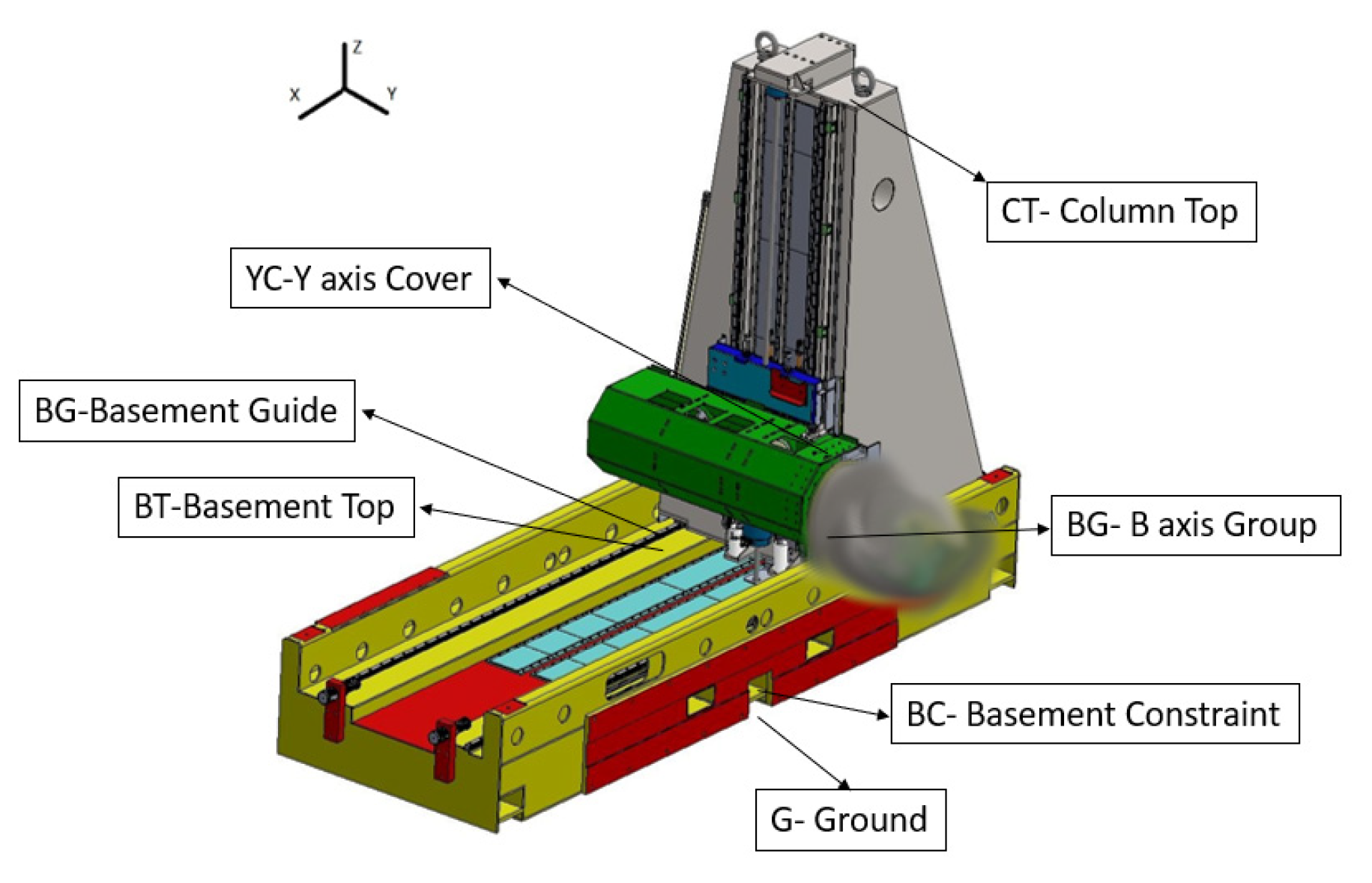
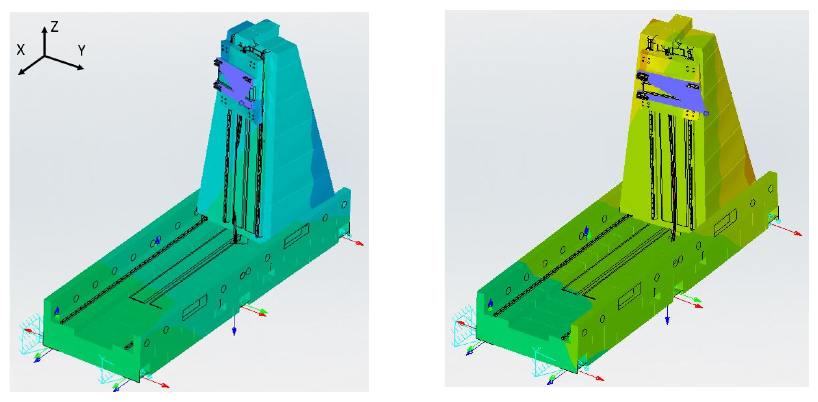
- A constraint sensitivity analysis was run on the basement constraints. The output frequencies were dependent on the constraint condition. In the initial configuration, a displacement constraint was directly applied to the surface area corresponding to the screw under-head. In the final model instead, a part of the screw was modeled as well, by considering the part emerging from the ground as a cantilever beam, connected in turn to the basement hole by means of an RBE3 connection.
- Flexible beam elements with RBE3 node distribution were used, instead of rigid beams with RBE2 distribution, to model the screws between tracks and basement, slides and column, and tracks and column.
- Evaluate if the 10 modes are sufficient to completely characterize the structure from a dynamic point of view. In general, if the sum over the modes of the EMFs for each direction falls around 80–90%, there is no need to consider higher-order modes.
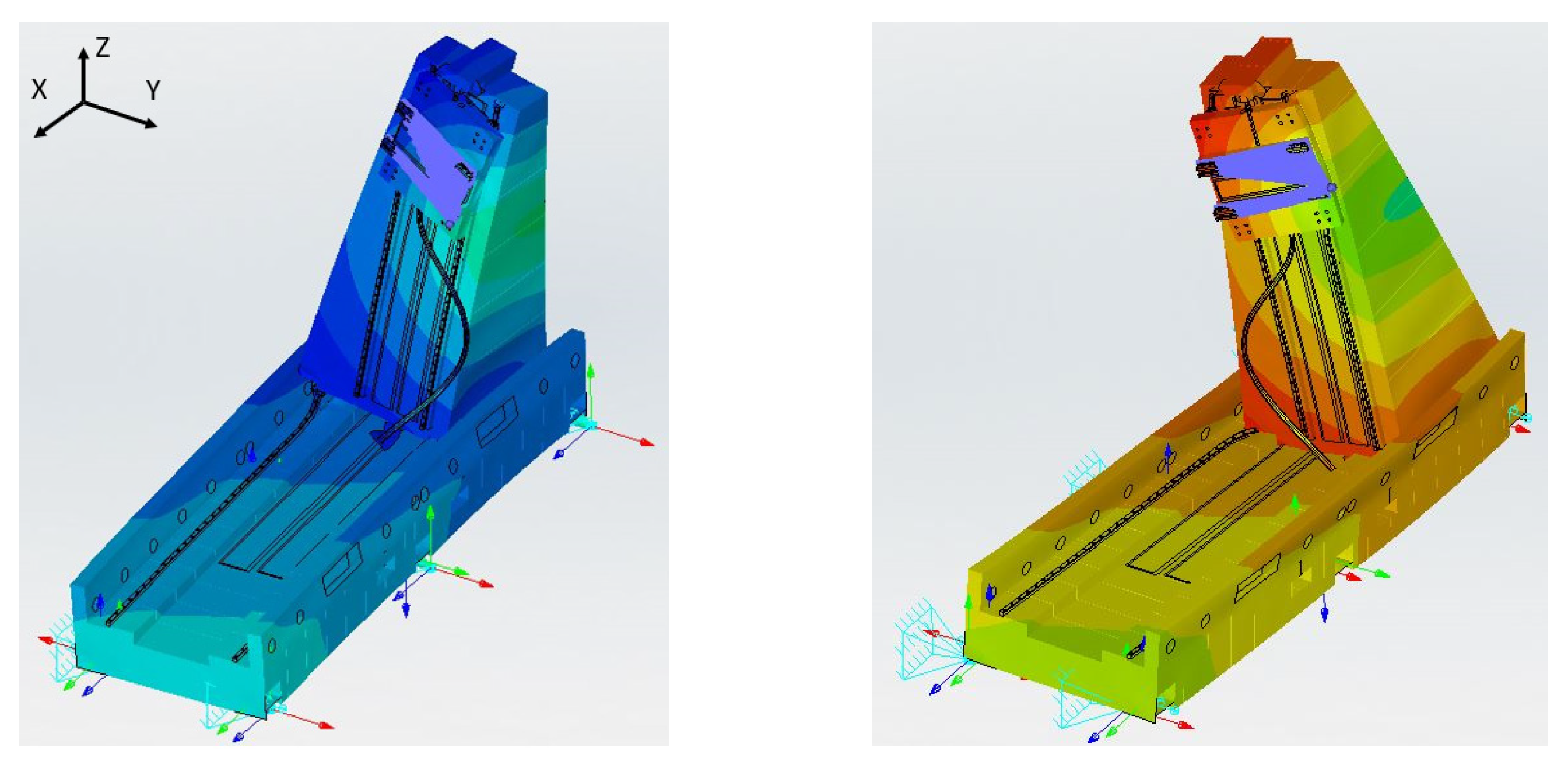
- Define which modes are relevant, since the EMF provides an indication of the energy associated with each mode. In Table 2, the effective mass fraction is reported as a function of the mode number and displacement direction. In this case, six modes were considered as global ones, namely Mode No. 1–8, because they have a non-negligible (<10−1) EMF along a particular direction.
- The low-frequency modes are the critical ones during operation, as confirmed by experimental characterization, i.e., cut samples and dynamic measurements;
- A single mass damper can provide a fast and efficient solution for the simultaneous vibration control of both modes since they are close in frequency;
- The maximum oscillation amplitude of the first two modes is in correspondence with the column top;
- The column top provides enough space to host the dynamic damper without inducing heavy design modification on the already existing prototype.
2.3.2. Frequency Response Analysis
3. Tuned Mass Damper (TMD)
- Experimental analysis showed the column oscillating along the X and Y directions at 20 Hz when the Z-Carriage and Y-Group were at their stroke ends, and at 24 Hz when they are completely retracted; therefore, the damping device has to be able to provide simultaneous oscillation neutralization along two different directions.
- The numerical model showed some reasonable discrepancies with respect to the experimental results, even though it provided consistent and useful information. Despite these differences, the numerical model was exploited for the dynamic damper tuning, by acting on the most critical frequency, aware of the fact that some differences may be present in practice.
- To provide the same stiffness independently of the direction, which leads to the choice of a cylindrically shaped spring.
- To keep the mass ratio as low as possible to secure the Cartesian robot performances.
- To be tuned at a frequency close to 20 Hz, as it was the most dangerous, but with the possibility of changing the frequency slightly, depending on the actual resonant frequency of the machine in operating condition. Therefore, additional masses were considered, to be added in a simple way to the principal one. Being the masses small with respect to the whole structure, no significant variations are induced in the mass ratio.
- To realize a compact design to be assembled on the column top.
- The mass ratio μ, between the dynamic damper mass md and the structure mass Mr, was selected, and the dynamic damper mass was evaluated according to Equation (2). In order to make the initial evaluation easier, an initial mass ratio of 1.55% was selected, valid both for the X direction and the Y direction. The main idea behind this was to avoid too heavy a dynamic damper, but still allow the dynamic damping capabilities and use the same mass along both directions.
- The stiffness of the dynamic damper, kd, was computed by relying on a simple 1-DoF equivalent model as follows.where
- Diameter D, height h, and shear modulus G were selected according to Equation (5). The geometric parameters are related to the dynamic damper spring dimensions, whilst the shear moduli to its material.
- CAD design was carried out.
- FEM modal and frequency response analyses were performed to verify the proposed solution.
3.1. Single Spring Design
3.2. Parallel Springs Design
3.2.1. TMD Tuning
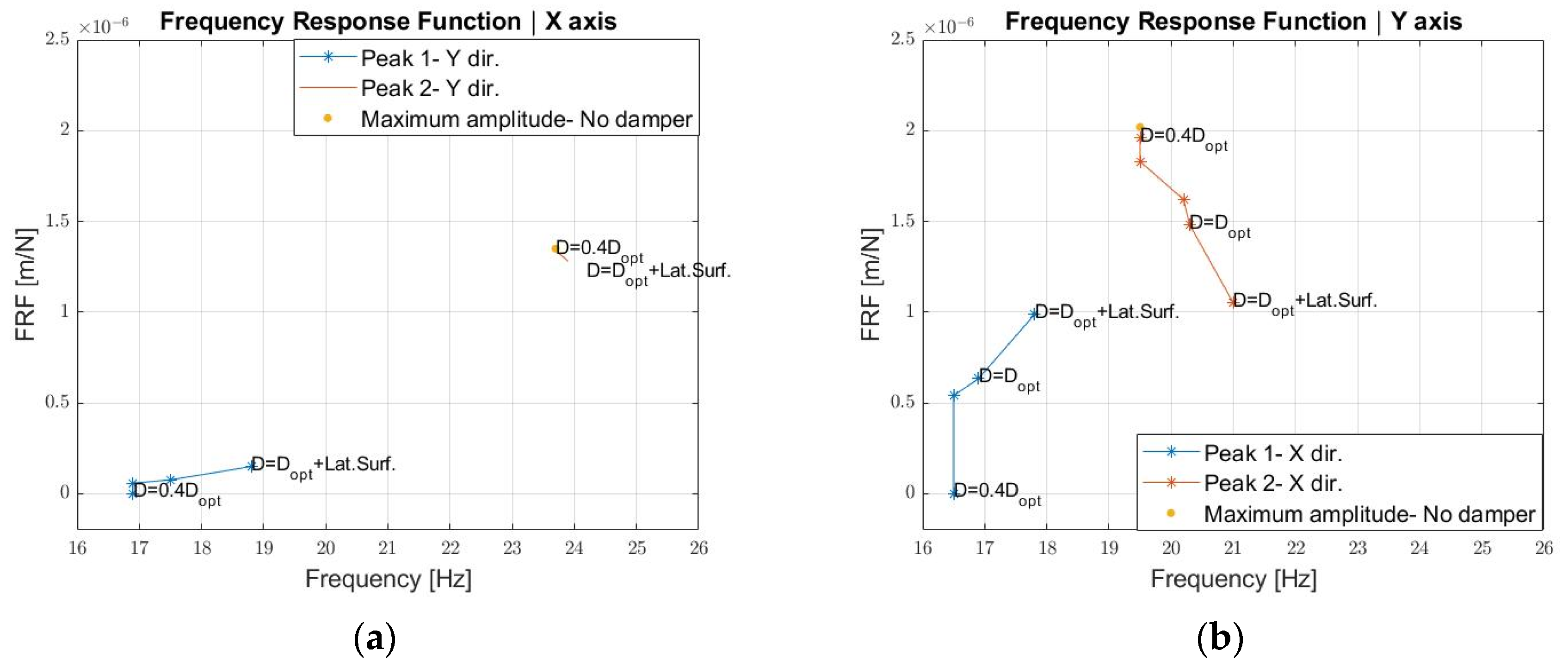
- With a mass of 34.7 kg (green thick curve), the FRF maximum along the Y direction can be reduced by 50%, even though two peaks are present, as expected. It must also be highlighted that in this numerical calculation the additional damping of the rubber element was not considered; therefore, a higher reduction may be expected from a practical point of view.
- The dynamic damper is less effective in the X axis since the maximum amplitude reduction is 20%.

3.2.2. Stiffness Distribution Analysis
3.2.3. Damping Estimation
- How much the robot response was affected by the damping effect of the elastomeric material.
- How the robot response may vary as a function of the working temperature, considering that the loss factor shows a linear dependence on the temperature for the considered range of 20–60 °C.
3.2.4. Criticalities Evaluation
- Uncertainties of the Young and consequently of the shear moduli.
- Imperfect gluing of the components.
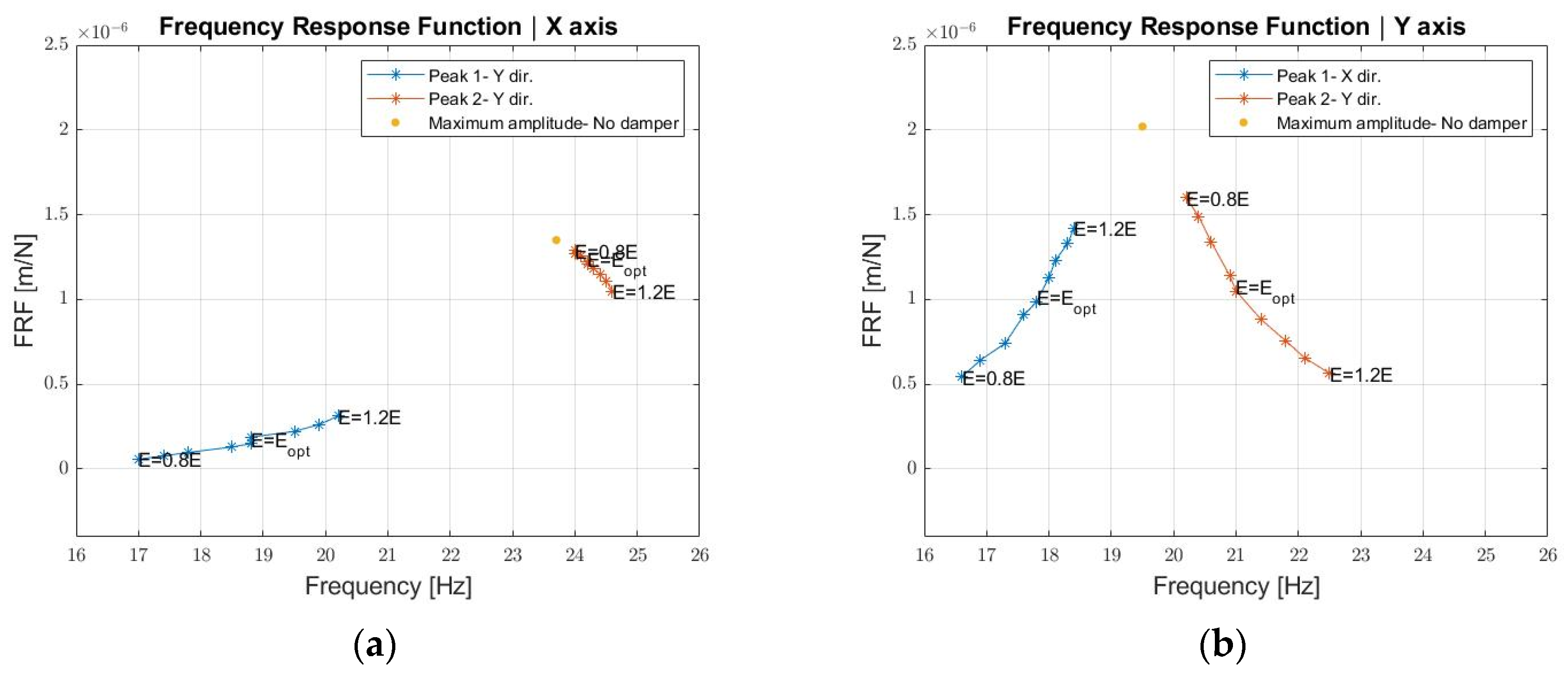
- If the Young modulus decreases, the first peak amplitude decreases as well as its frequency, on the contrary, the second peak increases in amplitude and decreases in frequency along both the X and Y directions. As a result, the FRF shifts left. Overall, a 20% reduction of the Young modulus still guarantees the TMD effectiveness, but to a reduced extent, as the FRF maximum decreases by 21% along the X axis and 4% along the Y axis with respect to the case without dynamic damper.
- If the Young modulus increases, the first peak increases both in amplitude and frequency, whilst the second peak decreases in amplitude and increases in frequency along both the X and Y directions. A frequency increase happens in this case for the two peaks of the FRF. A 20% increase in the Young modulus guarantees the TMD effectiveness, but the FRF maximum decreases by 30% along the X direction and 22% along the Y direction with respect to the case without the dynamic damper. From a design point of view, if uncertainties on the material elastic modulus are high, it would be then beneficial to select a stiffer material and perform the tuning of the damper by adding more masses.
4. Conclusions
Author Contributions
Funding
Institutional Review Board Statement
Informed Consent Statement
Data Availability Statement
Conflicts of Interest
References
- Brennan, M.J.; Ferguson, N.S. Vibration control. In Advanced Applications in Acoustics, Noise and Vibration, 1st ed.; Fahy, F., Walker, J., Eds.; Spoon Press: New York, NY, USA, 2004; Volume 4. [Google Scholar]
- Nad, M. Structural dynamic modification of vibrating systems. J. Appl. Comput. Mech. 2007, 1, 203–214. [Google Scholar]
- Neubauer, M.; Schwaericke, F.; Radmann, V.; Sarradj, E.; Modler, N.; Dannemann, M. Material Selection Process for Acoustic and Vibration Applications Using the Example of a Plate Resonator. Materials 2022, 15, 2935. [Google Scholar] [CrossRef] [PubMed]
- Karnopp, D. Active and semi-active vibration isolation. In Proceedings of the Sixth Cairo University International MDP Conference, Cairo, Egypt, 2–4 January 1996. [Google Scholar] [CrossRef]
- Baz, A.M. Active and Passive Vibration Damping, 1st ed.; John Wiley & Sons Inc: New York, NY, USA, 2019. [Google Scholar]
- Ashock, B.; Jeevanantham, A.K.; Vignesh, R.; Bhat Hire, K.R.; Prabhu, K.; Raaj Kumar, R.A.; Shivshankar, N.; Sudhagar, P.E. Calibration of engine parameters and fuel blend for vibration and noise characteristics in CRDI engine fuelled with low viscous biofuel. Fuel 2021, 288, 203–214. [Google Scholar] [CrossRef]
- Nguyen, V.; Johnson, J.; Melkote, S. Active vibration suppression in robotic milling using optimal control. Int. J. Mach. Tools Manuf. 2020, 152, 103541. [Google Scholar] [CrossRef]
- Pelàez, G.; Pelaez, G.; Perez, J.M.; Vizàan, A.; Bautista, E. Input shaping reference commands for trajectory following Cartesian machines. J. Control. Eng. Pract. 2005, 13, 941–958. [Google Scholar] [CrossRef]
- Kasprowiak, M.; Parus, A.; Hoffmann, M. Vibration Suppression with Use of Input Shaping Control in Machining. Sensors 2022, 22, 2186. [Google Scholar] [CrossRef]
- De Luca, A.; Book, W.J. Robots with Flexible Elements. In Springer Handbook of Robotics, 1st ed.; Siciliano, B., Khatib, O., Eds.; Springer Nature: Cham, Switzerland, 2016. [Google Scholar]
- Ramesh, R.; Mannan, M.A.; Poo, A.N. Error compensation in machine tools—A review. Part I: Geometric, cutting-force induced and fixture-dependent errors. J. Mach. Tools Manuf. 2000, 40, 1235–1256. [Google Scholar] [CrossRef]
- Gao, H.; Sun, J.; Chen, W.; Zhang, Y.; Wu, Q. Structural bionic design for a machine tool column based on leaf veins. J. Mech. Eng. Sci. 2017, 232, 2764–2773. [Google Scholar] [CrossRef]
- Yan, S.; Li, B.; Hong, J. Bionic design and verification of high-precision machine tool structures. J. Adv. Manuf. Technol. 2015, 81, 73–85. [Google Scholar] [CrossRef]
- Li, B.; Hong, J.; Liu, Z. Stiffness design of machine tool structures by a biologically inspired topology optimization method. J. Mach. Tools Manuf. 2014, 84, 33–44. [Google Scholar] [CrossRef]
- Zamora-Garcia, D.A.; Ramirez-Reivich, A.C.; Corono-Lira, M.P. On the Use of Tuned Mass Dampers for Reducing the Nonlinear Vibrations of Planar Parallel Cable Robots. Int. J. Mech. Eng. Robot. Res. 2019, 8, 406–412. [Google Scholar] [CrossRef]
- Bahrami, M.R.; Abed, S.A. Mechanics of robot inspector on electrical transmission lines conductors: Performance analysis of dynamic vibration absorber. J. Vibroeng. 2019, 25, 60–64. [Google Scholar] [CrossRef]
- Mrad, C.; Okabe, S.; Kamiya, Y.; Seki, H. Vibration Control of Mobile Robot Vehicle by Dynamic Vibration Absorber. JSME Int. J. 1999, 42, 62–70. [Google Scholar] [CrossRef]
- Bian, Y.; Liang, X.; Gao, Z. Vibration Reduction for a Flexible Arm Using Magnetorehological Elastomer Vibration Absorber. J. Shock. Vib. 2018, 2018, 9723538. [Google Scholar] [CrossRef]
- Yuan, H.; Wan, M.; Yang, Y. Design of tunable mass damper for mitigating vibrations in milling of cylindrical parts. Chin. J. Aeronaut. 2019, 32, 748–758. [Google Scholar] [CrossRef]
- Yang, Y.; Dai, W.; Liu, Q. Design and implementation of two-degree-of-freedom tuned mass damper in milling vibration mitigation. J. Sound Vib. 2015, 335, 78–88. [Google Scholar] [CrossRef]
- Ma, W.; Yu, J.; Yang, Y.; Wang, Y. Optimization and Tuning of Passive Tuned Mass Damper Embedded in Milling Tool for Chatter Mitigation. J. Manuf. Mater. Prop. 2020, 5, 2. [Google Scholar] [CrossRef]
- Lee, J.; Kim, C.J.; Lee, C.; Oh, C. Optimal Design of Multiple Tuned Mass Dampers to Reduce Vibrations of a Ram-Type Structure with Varying Dynamics via a Control Theoretic Framework. J. Manuf. Sci. Eng. 2020, 142, 021009. [Google Scholar] [CrossRef]
- Genta, G. Vibration Dynamics and Control, 1st ed.; Springer Nature: Cham, Switzerland, 2009. [Google Scholar] [CrossRef]
- Frahm, H. Device for Damping Vibrations of Bodies. US Patent No: 989,958, 18 April 1911. [Google Scholar]
- Den Hartog, J.P. Mechanical Vibrations, 1st ed.; McGraw-Hill: New York, NY, USA, 1956. [Google Scholar]
- Rana, R.; Soong, T.T. Parametric study and simplified design of tuned mass dampers. J. Eng. Struct. 1997, 20, 193–204. [Google Scholar] [CrossRef]
- Warburton, G.B. Optimum abrosber parameters for various combinations of response and excitation parameters. J. Earthq. Eng. Struct. Dyn. 1982, 10, 381–401. [Google Scholar] [CrossRef]
- Marano, G.C.; Greco, R.; Chiaia, B. A comparison between different optimization criteria for tuned mass dampers design. J. Sound Vib. 2010, 329, 4880–4890. [Google Scholar] [CrossRef]
- Leung, A.Y.T.; Zhang, H. Particle swarm optimization of tuned mass dampers. J. Eng. Struct. 2009, 31, 715–728. [Google Scholar] [CrossRef]
- Ahsan, R.; Rana, S.; Ghani, S.N. Cost Optimum Design of Posttensioned I-Girder Bridge Using Global Optimization Algorithm. J. Struct. Eng. 2012, 138, 273–284. [Google Scholar] [CrossRef]
- Javidialesaadi, A.; Wierschem, N.E. Design and performance evaluation of inerter-based tuned mass dampers for a ground acceleration excited structure. Soil Dyn. Earthq. Eng. 2021, 140, 106463. [Google Scholar] [CrossRef]
- Desu, N.B.; Deb, S.K.; Dutta, A. Coupled tuned mass dampers for control of coupled vibrations in asymmetric buildings. J. Struct. Control Health Monit. 2006, 13, 897–916. [Google Scholar] [CrossRef]
- Li, Y.; Li, J.; Du, H. A state-of-the-art review on magnetorheological elastomer devices. J. Smart Mater. Struct. 2006, 15, 897–916. [Google Scholar] [CrossRef]
- Deng, H.; Gong, X.; Wang, L. Development of an adaptive tuned vibration absorber with magnetorheological elastomer. J. Smart Mater. Struct. 2006, 15, N111–N116. [Google Scholar] [CrossRef]
- Plesseira, J.P.; Rochus, P.; Defise, J.M. Effective modal masses. In Proceedings of the 5th Congrés National de Méecanique Théorique et Appliquée, Louvain-la-neuve, Belgium, 23–24 May 2000. [Google Scholar]
- Ahmad, M.S.; Jamil, M.; Iqbal, J.; Khan, M.N.; Malik, M.H.; Butt, S.I. Modal Analysis of Ship’s Mast Structure using Effective Mass Participation Factor. Indian J. Sci. Technol. 2016, 9, 1–5. [Google Scholar] [CrossRef]
- Geant, A.N. On the relation between indentation hardness and Young’s modulus. J. Rubber Chem. Technol. 1958, 31, 896–906. [Google Scholar] [CrossRef]
- Nazirah, A. A methodology for Developing High Damping Materials with Applications to Noise Reduction of Railway Track. Ph.D. Thesis, University of Southampton, Southampton, UK, February 2009. [Google Scholar]





| Direction | Moving Mass (kg) | Nominal Force (N) | Peak Force (N) | Acceleration (m/s2) | Speed (m/s) | Stroke (mm) |
|---|---|---|---|---|---|---|
| X | 2026 | 10,000 | 20,000 | 10 | 5 | 2400 |
| Y | 360 | 2500 | 4700 | 10 | 4 | 1270 |
| Z | 569 | 6000 | 12,000 | 10 | 2 | 325 |
| Mode | Frequency (Hz) | EMF X Direction (-) | EMF Y Direction (-) | EMF Z Direction (-) |
|---|---|---|---|---|
| 1 | 19.5 | 7.3 × 10⁻⁴ | 4.1 × 10⁻¹ | 4.2 × 10⁻³ |
| 2 | 23.7 | 3.7 × 10⁻¹ | 6.0 × 10⁻⁵ | 3.5 × 10⁻² |
| 3 | 43.4 | 5.9 × 10⁻⁴ | 1.0 × 10⁻³ | 8.2 × 10⁻⁴ |
| 4 | 47.6 | 4.6 × 10⁻³ | 3.5 × 10⁻⁴ | 3.6 × 10⁻³ |
| 5 | 50.6 | 1.1 × 10⁻² | 1.3 × 10⁻¹ | 1.3 × 10⁻¹ |
| 6 | 53.0 | 2.0 × 10⁻¹ | 2.1 × 10⁻³ | 1.8 × 10⁻¹ |
| 7 | 68.1 | 4.6 × 10⁻² | 2.9 × 10⁻¹ | 1.1 × 10⁻¹ |
| 8 | 75.4 | 3.6 × 10⁻¹ | 1.2 × 10⁻² | 1.3 × 10⁻¹ |
| 9 | 80.1 | 2.8 × 10⁻⁵ | 7.7 × 10⁻² | 2.2 × 10⁻¹ |
| 10 | 90.6 | 7.6 × 10⁻⁵ | 5.8 × 10⁻² | 3.0 × 10⁻³ |
| Quantity | Value |
|---|---|
| Frequency band (Hz) | 16–26 |
| Frequency resolution (Hz) | 0.1 |
| Fx (N) | 1 |
| Fy (N) | 1 |
| Critical damping fraction (-) | 0.02 |
| Quantity | Single Spring Design | Parallel Springs Design |
|---|---|---|
| fd,1-DoF (Hz) | 20.3 | 20.1 |
| fd,Num (Hz) | 15.2 | 19.0 |
| md (kg) | 29.5 | 29.6 |
| Bm (mm) | 195 | 130 |
| Wm (mm) | - | 170 |
| Hm (mm) | 93 | 121 |
| kd,tot (kN/m) | 478.9 | 472.9 |
| Dk (mm) | 115 | 115 |
| Hk (mm) | 32 | 32 |
| Gk (MPa) | 1.5 | 0.8 |
| S (Shore A) | 65 | 50 |
Publisher’s Note: MDPI stays neutral with regard to jurisdictional claims in published maps and institutional affiliations. |
© 2022 by the authors. Licensee MDPI, Basel, Switzerland. This article is an open access article distributed under the terms and conditions of the Creative Commons Attribution (CC BY) license (https://creativecommons.org/licenses/by/4.0/).
Share and Cite
D’Imperio, S.; Berruti, T.M.; Gastaldi, C.; Soccio, P. Tunable Vibration Absorber Design for a High-Precision Cartesian Robot. Robotics 2022, 11, 103. https://doi.org/10.3390/robotics11050103
D’Imperio S, Berruti TM, Gastaldi C, Soccio P. Tunable Vibration Absorber Design for a High-Precision Cartesian Robot. Robotics. 2022; 11(5):103. https://doi.org/10.3390/robotics11050103
Chicago/Turabian StyleD’Imperio, Simone, Teresa Maria Berruti, Chiara Gastaldi, and Pietro Soccio. 2022. "Tunable Vibration Absorber Design for a High-Precision Cartesian Robot" Robotics 11, no. 5: 103. https://doi.org/10.3390/robotics11050103
APA StyleD’Imperio, S., Berruti, T. M., Gastaldi, C., & Soccio, P. (2022). Tunable Vibration Absorber Design for a High-Precision Cartesian Robot. Robotics, 11(5), 103. https://doi.org/10.3390/robotics11050103


