Article

Body-Powered and Portable Soft Hydraulic Actuators as Prosthetic Hands

Department of Mechanical and Mechatronics Engineering, The University of Auckland, Auckland 1010, New Zealand
*
Author to whom correspondence should be addressed.
Robotics 2022, 11(4), 71; https://doi.org/10.3390/robotics11040071
Submission received: 12 May 2022 / Revised: 22 June 2022 / Accepted: 1 July 2022 / Published: 5 July 2022

Abstract

:
Soft robotic actuators are highly flexible, compliant, dexterous, and lightweight alternatives that can potentially replace conventional rigid actuators in various human-centric applications. This research aims to develop a soft robotic actuator that leverages body movements to mimic the function of human fingers for gripping and grasping tasks. Unlike the predominantly used chamber-based actuation, this study utilizes actuators made from elastomers embedded with fiber braiding. The Young’s modulus of the elastomer and braiding angles of the fiber highly influenced the bending angle and force generated by these actuators. In this experiment, the bending and force profiles of these actuators were characterized by varying the combinations of elastomeric materials and braiding angles to suit hand manipulation tasks. Additionally, we found that utilizing water, which is relatively more incompressible than air, as the actuation fluid enabled easier actuation of the actuators using body movements. Lastly, we demonstrated a body-powered actuator setup that can provide comfort to patients in terms of portability, standalone capability, and cost effectiveness, potentially allowing them to be used in a wide range of wearable robotic applications.

1. Introduction

Researchers have adapted the term soft robotics to describe the usage of soft, flexible, and deformable materials in robots [1]. Soft materials have been extensively used in bio-robotic applications, such as in prosthetic hands and in the stimulation of human actions in assistive devices, especially for stroke patients [2]. One such area of research is wearable robotics, where robotic actuators can replace or assist with certain actions performed by humans [3,4,5]. Wearable soft robots serve to provide an alternative approach to utilizing soft actuators made of flexible materials, such as polymers or fabrics, to produce assistive devices that can be more compliant and lightweight for safe human interactions [6]. In addition, soft robotic actuators stand as an attractive alternative to their rigid mechanical counterparts in terms of manufacturing, actuation, setup time, portability, and cost effectiveness [4]. Since the level of damage that can be caused due to malfunctioning of soft robotic actuators is very minimal, they can be used in unsupervised home-based therapies, thus reducing the involvement of manpower and costs [7]. Effective closed-loop control can be established by incorporating sensing capabilities into a soft actuator, leading to highly sensitive applications, such as smart gloves for delicate grasping tasks [8] and surgical grippers [9].
Piezo-electric actuators provide an alternative approach to providing high actuation accuracy, but their high actuation voltage requirement and rather difficult assembly process make them unsuitable for interactive human applications [10]. Unlike the powering of motors in each joint to promote bending in rigid electromechanical actuators, soft actuators use a single pneumatic or hydraulic source [11,12]. Various materials have been extensively researched for the manufacture of soft actuators, such as Dragon Skin, hydrogels, thermoplastic polyurethane fabrics, and other elastomer-based materials [13]. These traditional soft actuators utilize chamber-based actuation techniques to achieve bending for use in hand-assistive devices and soft exoskeletons [14]. However, avoiding the chambers can potentially reduce the size and mass of the actuators. Fabric-based actuators overcome the difficulty of bulkiness faced in the previous scenario and involve reduced material usage and manufacturing costs [15], but are susceptible to leaks over time and, hence, have a reduced life span. Chamber-based 3D-printed actuators provide stability and repeatable bending outcomes, are capable of achieving higher blocking force outputs that are comparable to the force generated by human fingers, and can deal with relatively heavier objects [16], but the options of materials limit them.
Single-core actuators reduce material usage and possess simple actuation techniques. Making one side of the cylinder flat, attaching it to a strain-limiting layer [17], and braiding fibers around it will constrain bulging, leading to a bending motion. Different combinations of braiding can generate complex dynamic motions, such as twisting, extension, contraction, and bending [18]. However, the usage of an external strain-limiting layer can be avoided, and bending can solely be generated by creating an angle difference between the two semi-cylindrical sides of the cylinder using fibers [19]. The difference in the angles on either side of the actuator creates a variable stiffness in the actuator’s core, creating bending under pressure [20]. In this case, rubber was used as the outer material, which involved vulcanizing and molding it through a complicated process at temperatures as high as 190 °C [19], making it complicated to manufacture and requiring high pressure for actuation. Instead, elastomers with a low Young’s modulus will be a suitable option, as they require a low actuation pressure, as demonstrated in our previous work [21]. This will open the opportunity to utilize body movements to power these actuators due to their low operating range. Several studies have been performed to investigate body-powered actuation for prosthetic arms or therapeutic robots [22,23,24,25,26]. However, most of these devices either involved assemblies with heavy parts or came with complicated designs that were not easy to handle, which limited their application for portable prosthetic arms [27,28,29].
We hypothesize that the design of soft elastomeric actuators with appropriately embedded fibers will result in a more controllable actuation and output force with low input pressure. In addition, we hypothesize that, by integrating these soft elastomeric actuators that can operate at a lower input pressure range, they can be easily powered by simple body movements that enhance the portability and minimize the complication in the design of a prosthetic arm. Simple, ready-to-wear, lightweight, and easy-to-handle devices are always desirable to users. Hence, developing a simpler and easier fabrication method for elastomeric actuators with body-powered actuation would be greatly beneficial for grasping and gripping applications.
Here, we report on (1) an actuator design based on a fiber-braided elastomer and (2) the bending performance and blocking force output characterized by different elastomeric actuators. Additionally, a syringe-powered bending actuator (3) was studied, where the syringe was prefilled with air or water and the plunger’s displacement is proportional to the increase in pressure. Lastly, the actuator was (4) integrated into a wearable body-powered prosthetic hand that used simple shoulder-shrugging movements to power the actuators to grasp an object.

2. Experimental Section

2.1. Materials and Preparation

This study comprises extended work on our previously proposed actuator [21]. A continuous fiber-reinforcement technique was used to create a combination of braiding angles that generated variable stiffness around the core of the actuator, which led to bending when pressurized. The fabrication of the actuator required a minimum of materials, including an aluminum rod, guiding pins, fibers, and elastomers, as shown in Figure 1. A 250 mm long hollow aluminum rod (10 mm ⌀) was coated with a thin layer of elastomeric material during fabrication. Later, fibers were braided over 60 mm long steel guiding pins (1 mm ⌀), which were cross-sectionally inserted into the aluminum rod. The commercially available 0.4 mm diameter KastKing Superpower braided fishing line with a breaking load of 227 N was used to create a braiding fiber in the actuator. Commercially available elastomers that offered a wide range of elastic moduli were chosen, including Ecoflex™ 00-30, Ecoflex™ 00-50, and Smooth-Sil™-940. The Young’s moduli of these three materials were experimentally determined using an Instron machine with a 30 kN load cell using the ASTM D638 standard. The results are shown in Table 1.

2.2. Fabrication of the Fiber-Reinforced Elastomeric Actuator

The fabrication started by coating a thin layer of one of the elastomer materials (Ecoflex 00-30, Ecoflex 00-50, or Smooth-Sil) on an aluminum rod, as shown in Figure 1a. The assembly was degassed in a vacuum chamber to remove the extra bubbles formed during mixing. The mixing ratio and curing time were followed as per the procedure described for the elastomer. Once cured, the steel guiding pins were inserted every 2 mm along the length of the rod, as shown in Figure 1b. Two different braiding angles on either half were made by running the fiber around the guiding pins. A previous publication by our group found that 10°/80° was the best braiding angle combination for the soft actuator, as it produced the maximum bending displacement and blocking force [19]. The braiding started at 10° on one side of the rod and 80° on the other side of the rod, and the braiding was repeated until the rod was completed, as shown in Figure 1c. As the next step, the elastomer mix was applied to the fibers to keep them intact, holding the braid in place. Once cured, the guiding pins were removed, and the holes created by the pins were sealed by using the elastomer (Figure 1d). A 3D-printed cap was attached to the tip of the actuator to block one end of the actuator. To enhance the strength, the actuator was placed in a cylindrical acrylic mold of 20 mm diameter and filled with the elastomer to create an additional outer layer of elastomer. A silicon pipe was fitted to the other end of the actuator using a Sil-poxy silicon adhesive to secure a leakproof pneumatic connection between the actuator and the power source (Figure 1e). Figure 1f shows the bending response of the fiber-reinforced soft elastomeric actuator at different pressures.

2.3. Characterization

As the aim was to actuate using body movement, a plastic syringe was used to pressurize the fluid. Hence, a characterization of the amount of force and displacement required by the plunger to bend the actuator was conducted. The fabricated bending actuators had a 20 mm outer diameter with an 8 mm hollow inner core and a length of 180 mm. These actuators were clamped to a holder that allowed the actuator to hang in a vertical direction with the inlet at the top. A linear motor was used to control the movement of the syringe’s plunger. The force measurement here was performed by using an aluminum alloy load cell from Top Sensor Technology Co., Ltd. (Foshan, China). Characterizations were conducted with the system pre-filled with air or water as a working fluid [27]. As the plunger was pushed, it pressurized the actuator, causing it to bend or curl upwards (Figure 2a). A camera was installed to track and record the bending of the actuator, and images were processed to obtain the bending angle relative to its equilibrium state (vertical position, 0°). In addition, a force sensor was attached to the plunger to measure the amount of force applied for actuation. This force, combined with the area of the plunger, could be converted into the pressure that was built up in the elastomeric actuators. For the measurement of the blocking force by the actuator, a second force sensor was attached to the rig close to the tip of the actuator (Figure 2b). Data acquired by these force sensors were read through myRIO using LabVIEW 2019 (National Instruments, Austin, TX, USA).

2.4. Evaluation of Shrugging Force

Ten (n = 10) healthy individual participants (2 female and 8 male) were recruited to convert their shoulder-shrugging movements to power the actuator. Before starting this study, each participant was briefed about the nature of this research and consented to follow the protocol approved by the University of Auckland’s Human Participants Ethics Committee (reference number UAHPEC23153). The participants were asked to shrug their shoulders, and the upward force and displacement were recorded. With the upward displacement and the force generated by the shoulder, the maximum pressure generated to actuate the number of actuators could be determined.

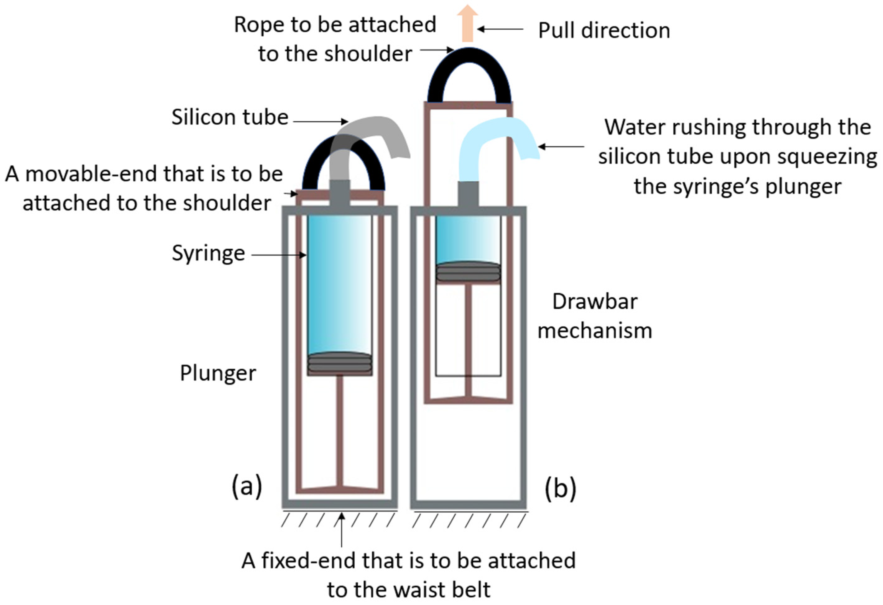
2.5. Draw-Bar Spring Mechanism for Body Power Generation

The design of the body-powered actuator relied on the draw-bar spring mechanism used in the syringe and plunger setup shown in Figure 3. The top end of this setup was strapped to the shoulder, and the bottom end was fixed to a belt at the waist. When the shoulder was shrugged, it pulled the plunger upwards, which squeezed the fluid inside the syringe, which could be used to power the actuators.

3. Results and Discussion

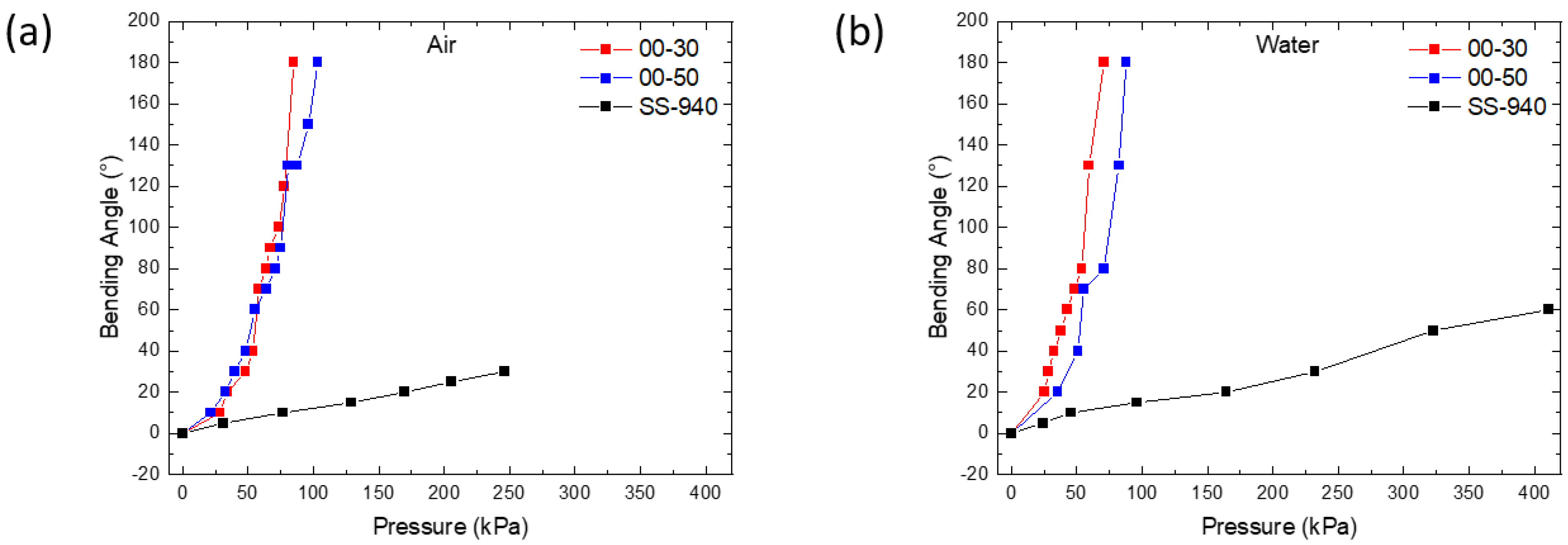
3.1. Bending Characteristics

As the motor pushed the plunger (Figure 2), the system filled with air or water, causing the actuator to bend in the direction where the fiber angle was 10°. This bending was the result of stress created on the inner walls of the actuator, where the higher angle in the braiding combination allowed more space to expand over a certain pressure, causing shrinkage on the side with the lower angle and resulting in curling when pressurized. When powered by air, both the Ecoflex 00-30 and Ecoflex 00-50 actuators quickly bent to 40° and 32° with 50 kPa, respectively, whereas the actuator made using Smooth-Sil 940 managed to reach only 8°, as shown in Figure 4a.
When the working fluid was changed from air to water, the Ecoflex 00-30 and Ecoflex 00-50 actuators reached 50° and 40° with 50 kPa, whereas Smooth-Sil 940 was slightly bent to 10° (Figure 4b). It could be seen that the amount of bending at any given pressure was affected by the elastomer’s Young’s modulus. These bending properties are consistent with those observed by Yap et al. and Galloway et al., who evaluated the bending performance for different materials from Smooth-On Inc., East Texas, PA, USA [30,31].

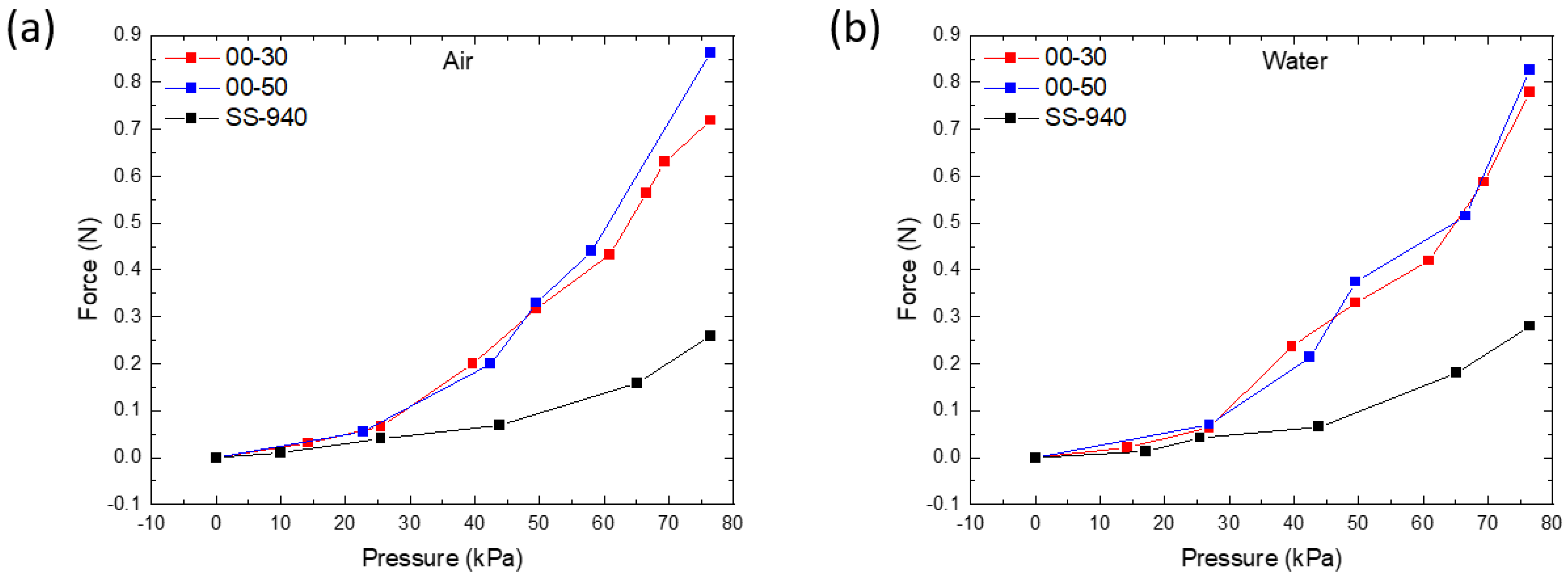
3.2. Force Characteristics

When the pressure is generated by air or water, this soft actuator can potentially be used to grip an object. The gripping force originates from the mechanical bending of the actuator and can be used in many applications, such as prosthetic hands. A strain gauge was used to measure the blocking force generated by the actuators made from Ecoflex 00-30, Ecoflex 00-50, and Smooth-Sil 940. The force blocked by the actuators was measured as the pressure was increased up to 76 kPa (Figure 5). It was noted that there was a gradual increase in the force with input pressure at first, followed by a larger rate of increase. This was because the braided fiber was relaxed in the beginning and started to tighten when pressurized by extending slightly, causing radial stress. Once the stretching limit was exceeded, the fibers were inextensible, and the blocked force increased at a greater rate with pressure. At an air pressure of 76 kPa, the forces recorded by the Ecoflex 00-30, Ecoflex 00-50, and Smooth-Sil 940 actuators were measured to be 0.719, 0.864, and 0.260 N, respectively (Figure 5a). Similarly, the actuators pressurized with water demonstrated an almost identical pattern and achieved maximum forces of 0.779, 0.827, and 0.280 N for the actuators made of Ecoflex 00-30, Ecoflex 00-50, and Smooth-Sil 940, respectively (Figure 5b). Compared with Ecoflex 00-30 and Ecoflex 00-50, the Smooth-Sil 940 actuator had a much lower blocking force when pressurized with both air and water. These mechanical properties were consistent with its stiffness, as the Ecoflex 00-30 and Ecoflex 00-50 actuators, with their lower moduli, could be actuated at lower pressures, and, with its higher modulus, the Smooth-Sil 940 actuator required a higher pressure for actuation, which resulted in a lower blocking force generated at the maximum tested pressure. Overall, the forces produced in all three elastomers were proportional to the input pressures, and the forces achieved with air and water actuation were almost equivalent. In addition, these results represent the fact that the bending and force performance of these soft actuators can be controlled with the pressure supplied. The relationship between the blocking force and input pressure can be further extended. Operating soft actuators at higher pressures affects their life span due to fatigue. However, these actuators were controlled with a fixed volume in a syringe, making them less likely to be overpowered, and they were tested for 500 cycles at a pressure of 100 kPa without failure. These soft actuators demonstrated blocking forces up to the ~1 N range, which is comparable to the range of existing elastomeric actuators [31,32,33,34]. Two or more soft actuators can serve as a body-powered gripper that can be used to grasp objects when actuated.

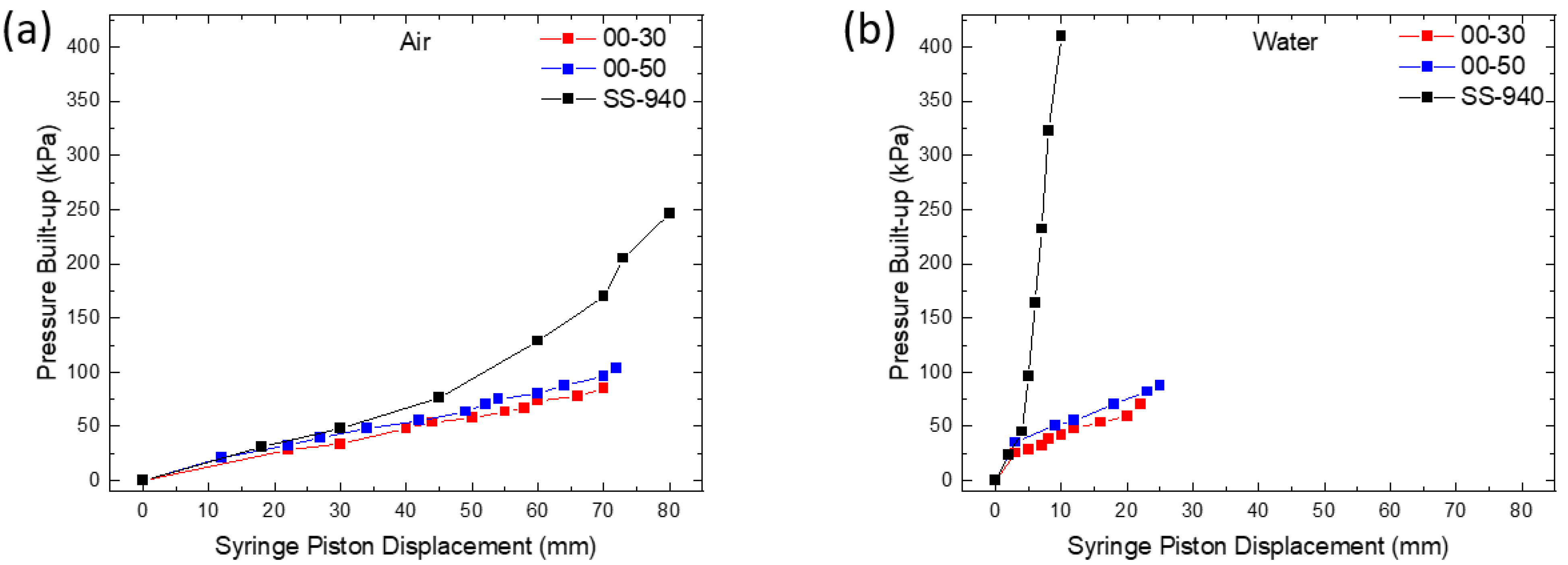
3.3. Syringe Plunger Displacement versus Pressure Built Up in the Actuator

The plunger displacement of the syringe and the pressure built up in the actuator due to this displacement are two crucial parameters for it to be powered by the body. The pressure built up, P, is determined by the force, F applied to the plunger for the given syringe dimensions. As the syringe is pre-filled with air or water, the fluid will experience a fixed working area, A (area of the plunger, 7.1 × 10⁻⁴ m2), and the pressure generated can be calculated using P = F/A [35,36,37]. Although all actuators have the same geometry, actuators that are much stiffer allow less expansion, causing pressure to build up in the actuator, which also implies that it requires a high pressure to bend, which is very difficult to achieve when using shoulder movements. To investigate this, we calculated the pressure built up with the help of a force sensor attached to the plunger. The built-up pressure increased almost linearly with increasing displacement in the plunger for the cases of the Ecoflex 00-30 and Ecoflex 00-50 actuators, whereas for the Smooth-Sil 940 actuator, it quickly rose as the displacement increased for both the air- and water-filled syringes (Figure 6). When the plunger was pushed to displace 20 mm in the syringe with air, the pressure in all three actuators was approximately 20 kPa (Figure 6a). On the other hand, when using water, the pressure quickly jumped to approximately 50 kPa in the actuators made from Ecoflex 00-30 and 00-50 and to approximately 380 kPa in the actuators made from Smooth-Sil 940 (Figure 6b) when the plunger pushed a similar amount. Further, it was observed that the displacement of the plunger needed to generate the same amount of pressure in the actuator was approximately three times lower when using water compared to air, as water is relatively incompressible [27] compared to air. Hence, the use of water as a working fluid in bending actuators is suitable in this body-powered actuator application, as a smaller body motion is required to generate the required pressure. In this case, the shoulder’s shrugging is considered as the body motion that actuates the bending actuators. Considering the bending angle, force, plunger displacement, and built-up pressure together, the actuators made from Ecoflex 00-30 and Ecoflex 00-50 had almost similar performance, but Ecoflex 00-50 had a slightly higher stiffness than Ecoflex 00-30, which limited the bending due to gravity when held horizontally. Therefore, an actuator made from Ecoflex 00-50 was chosen for this application.

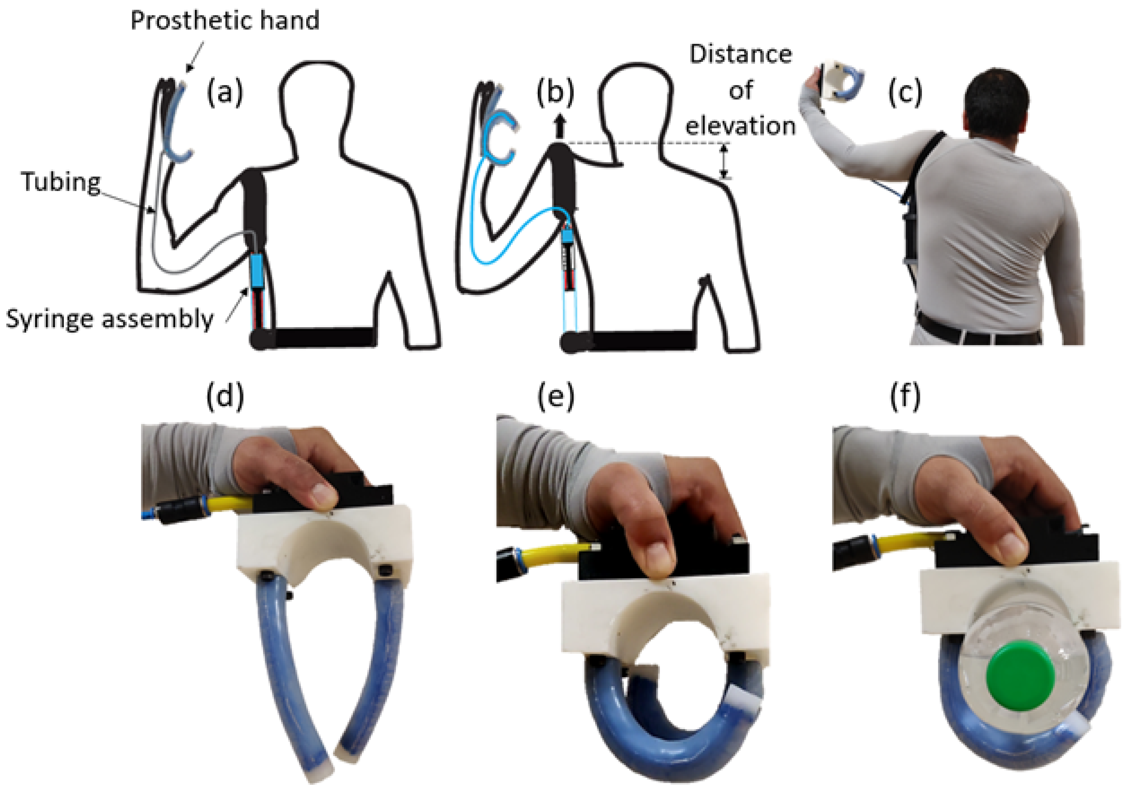
3.4. Application of Body-Powered Actuation

After determining the suitable elastomeric material and its actuation conditions, we applied them to a body-powered prosthetic hand with water as the working fluid. The shoulder-shrugging action was assumed to be able to squeeze the syringe using a draw-bar spring setup, as mentioned in the section on the methodology.
The test was conducted among ten healthy (two female and eight male) participants to determine the average upward displacement and force generated when shrugging the shoulder by using a measuring scale and a force sensor, respectively. The average shoulder elevation measured was 77 ± 29 mm. The average blocking force generated by shrugging the shoulder was 113 ± 55 N, which was equivalent to a pressure of 160 ± 78 kPa in the syringe with a plunger of 30 mm diameter and a total volume of 50 mL. As shown in Figure 4b, to bend the actuator to 120°, it required approximately 80 kPa, and to generate such pressure, the plunger had to move 25 mm (Figure 6b). Hence, based on the data collected from the 10 human participants, the shrugging of the shoulder could, in the worst case, displace the plunger by 48 mm, which was sufficient to actuate two actuators to bend 120° each using body power.
Instead of conventional actuators, which require an external pneumatic supply, using a simple assembly made from a syringe and a draw-bar, as shown in Figure 3, a body-powered prosthetic system can be realized. This application utilizes body movements as a source to generate hydraulic pressure to actuate these grippers. Hence, this will be lightweight and truly portable. In our proposed body-power setup, the bottom end of the setup was fixed to a belt at the waist to cause the syringe to stay in position when the shoulder was elevated, as the top end was strapped to the shoulder (Figure 7a). When the shoulder was elevated upwards, it pressurized the system and resulted in the bending of the actuators (Figure 7b). A photograph of the actual body-powered actuator being worn is shown in Figure 7c. Two actuators acting as fingers were connected to the syringe’s outlet using a silicone tube. Figure 7d,e show the fingers before and after actuation, respectively. Figure 7f shows the fingers grasping a water bottle with a weight of 500 g that was placed on a table; this was ten times more than the mass of the actuator itself, demonstrating a promising result for effective integration in soft robotic applications. In addition, we tested the two-actuator gripper to assess the amount of force required to dislodge an item, which was found to be 5.8 N. The actuator is currently limited to grasping cylindrical objects. Future development of this device will include testing of actuators of different lengths and a gripper that resembles a five-fingered human hand that can potentially grasp different objects irrespective of their shape and orientation.

4. Conclusions

The idea presented in this article represents a shift from the existing approach of using externally powered soft robots toward using body-powered robots. Prosthetics and wearable robots need to be portable, lightweight, and simple. Instead of using rigid linkages, as seen in traditional actuators powered by servo motors or chamber-based soft actuation techniques powered using external compressors, the proposed design is both soft and body powered; it bends based on the variable stiffness created using a composite of an elastomer and fibers braided along the length of the actuator while utilizing shoulder elevation for power. The actuators made from Ecoflex 00-30 and Ecoflex 00-50 showed better bending and better blocking force compared to those of Smooth-Sil 940. In addition, Ecoflex 00-50 had a higher strength and could provide extra protection from bulging or failures at higher operating pressures. Therefore, Ecoflex 00-50 was chosen for these body-powered actuators. Lastly, we successfully demonstrated the body-powered actuator for grasping using a shoulder-shrugging motion to grasp a water bottle with a mass of 500 g. These actuators are highly suitable for applications that demand high bending angles with low input pressures.

Author Contributions

Conceptualization, S.K. and K.A.; Methodology, S.K. and K.A.; Experiment design, S.K. and K.A.; Data collection, S.K.; Formal analysis, S.K. and K.A.; Writing, S.K. and K.A.; Resources, K.A.; Validation, K.J. and K.A.; Review and editing, S.K., M.T., N.R., A.M., K.J. and K.A.; Supervision, A.M. and K.A. All authors have read and agreed to the published version of the manuscript.

Funding

This research received no external funding.

Institutional Review Board Statement

The study was conducted according to the guidelines approved by the University of Auckland’s Human Participants Ethics Committee. Reference: UAHPEC23153.

Informed Consent Statement

Informed consent was obtained from all subjects involved in the study.

Data Availability Statement

Not applicable.

Conflicts of Interest

The authors declare no conflict of interest.

References

  1. Bao, G.; Fang, H.; Chen, L.; Wan, Y.; Xu, F.; Yang, Q.; Zhang, L. Soft Robotics: Academic Insights and Perspectives Through Bibliometric Analysis. Soft Robot. 2018, 5, 229–241. [Google Scholar] [CrossRef] [PubMed]
  2. Datteri, E. The Logic of Interactive Biorobotics. Front. Bioeng. Biotechnol. 2020, 8, 637. [Google Scholar] [CrossRef] [PubMed]
  3. Park, Y.-L.; Chen, B.; Pérez-Arancibia, N.O.; Young, D.; Stirling, L.; Wood, R.J.; Goldfield, E.C.; Nagpal, R. Design and control of a bio-inspired soft wearable robotic device for ankle–foot rehabilitation. Bioinspir. Biomim. 2014, 9, 016007. [Google Scholar] [CrossRef]
  4. Walsh, C. Human-in-the-loop development of soft wearable robots. Nat. Rev. Mater. 2018, 3, 78–80. [Google Scholar] [CrossRef]
  5. Agarwal, G.; Besuchet, N.; Audergon, B.; Paik, J. Stretchable Materials for Robust Soft Actuators towards Assistive Wearable Devices. Sci. Rep. 2016, 6, 34224. [Google Scholar] [CrossRef] [Green Version]
  6. Majidi, C. Soft Robotics: A Perspective—Current Trends and Prospects for the Future. Soft Robot. 2014, 1, 5–11. [Google Scholar] [CrossRef]
  7. Martinez, R.V.; Glavan, A.C.; Keplinger, C.; Oyetibo, A.I.; Whitesides, G.M. Soft actuators and robots that are resistant to mechanical damage. Adv. Funct. Mater. 2014, 24, 3003–3010. [Google Scholar] [CrossRef] [Green Version]
  8. Amjadi, M.; Kyung, K.U.; Park, I.; Sitti, M. Stretchable, Skin-Mountable, and Wearable Strain Sensors and Their Potential Applications: A Review. Adv. Funct. Mater. 2016, 26, 1678–1698. [Google Scholar] [CrossRef]
  9. Guo, J.; Sun, Y.; Liang, X.; Low, J.H.; Wong, Y.R.; Tay, V.S.C.; Yeow, C.H. Design and fabrication of a pneumatic soft robotic gripper for delicate surgical manipulation. In Proceedings of the 2017 IEEE International Conference on Mechatronics and Automation (ICMA), Takamatsu, Japan, 6–9 August 2017; pp. 1069–1074. [Google Scholar] [CrossRef]
  10. Chappel, E.; Dumont-Fillon, D. Micropumps for drug delivery. In Drug Delivery Devices and Therapeutic Systems; Elsevier: Amsterdam, The Netherlands, 2021; pp. 31–61. [Google Scholar]
  11. Collie, A. Walking Robot. IEE Colloq. 1985, 19, 339–347. [Google Scholar]
  12. Yao, J.; Jiao, Z.; Ma, D.; Yan, L. High-accuracy tracking control of hydraulic rotary actuators with modeling uncertainties. IEEE/ASME Trans. Mechatron. 2014, 19, 633–641. [Google Scholar] [CrossRef]
  13. Coyle, S.; Majidi, C.; LeDuc, P.; Hsia, K.J. Bio-inspired soft robotics: Material selection, actuation, and design. Extrem. Mech. Lett. 2018, 22, 51–59. [Google Scholar] [CrossRef]
  14. Yap, H.K.; Lim, J.H.; Nasrallah, F.; Low, F.Z.; Goh, J.C.H.; Yeow, R.C.H. MRC-glove: A fMRI compatible soft robotic glove for hand rehabilitation application. In Proceedings of the 2015 IEEE International Conference on Rehabilitation Robotics (ICORR), Singapore, 11–14 August 2015; pp. 735–740. [Google Scholar] [CrossRef]
  15. Yap, H.K.; Khin, P.M.; Koh, T.H.; Sun, Y.; Liang, X.; Lim, J.H.; Yeow, C.-H. A Fully Fabric-Based Bidirectional Soft Robotic Glove for Assistance and Rehabilitation of Hand Impaired Patients. IEEE Robot. Autom. Lett. 2017, 2, 1383–1390. [Google Scholar] [CrossRef]
  16. Yap, H.K.; Ng, H.Y.; Yeow, C.-H. High-Force Soft Printable Pneumatics for Soft Robotic Applications. Soft Robot. 2016, 3, 144–158. [Google Scholar] [CrossRef]
  17. Wang, Z.; Polygerinos, P.; Overvelde, J.T.B.; Galloway, K.C.; Bertoldi, K.; Walsh, C.J. Interaction Forces of Soft Fiber Reinforced Bending Actuators. IEEE/ASME Trans. Mechatron. 2017, 22, 717–727. [Google Scholar] [CrossRef]
  18. Connolly, F.; Walsh, C.J.; Bertoldi, K. Automatic design of fiber-reinforced soft actuators for trajectory matching. Proc. Natl. Acad. Sci. USA 2017, 114, 51–56. [Google Scholar] [CrossRef] [PubMed] [Green Version]
  19. Wang, B.; Aw, K.C.; Biglari-Abhari, M.; McDaid, A. Design and fabrication of a fiber-reinforced pneumatic bending actuator. In Proceedings of the 2016 IEEE International Conference on Advanced Intelligent Mechatronics (AIM), Banff, AB, Canada, 12–15 July 2016; pp. 83–88. [Google Scholar] [CrossRef]
  20. Wang, B.; McDaid, A.; Giffney, T.; Biglari-Abhari, M.; Aw, K.C. Design, modelling and simulation of soft grippers using new bimorph pneumatic bending actuators. Cogent Eng. 2017, 4, 1285482. [Google Scholar] [CrossRef]
  21. Kandasamy, S.; Devaraj, H.; Stuart, L.; McDaid, A.; Aw, K.C. A novel varying angle fiber-reinforced elastomer as a soft pneumatic bending actuator. In Proceedings of the 3rd International Conference on Automation, Control and Robots, Praha, Czech Republic, 11–13 October 2019; pp. 50–54. [Google Scholar]
  22. Hashemi, S.; Durfee, W. Variable hydraulic transmission to be used in a body-powered wearable Robot. In Proceedings of the 2020 Design of Medical Devices Conference, Minneapolis, MN, USA, 6–9 April 2020; pp. 7–9. [Google Scholar] [CrossRef]
  23. Gerez, L.; Chen, J.; Liarokapis, M. On the Development of Adaptive, Tendon-Driven, Wearable Exo-Gloves for Grasping Capabilities Enhancement. IEEE Robot. Autom. Lett. 2019, 4, 422–429. [Google Scholar] [CrossRef]
  24. Trent, L.; Intintoli, M.; Prigge, P.; Bollinger, C.; Walters, L.S.; Conyers, D.; Miguelez, J.; Ryan, T. A narrative review: Current upper limb prosthetic options and design. Disabil. Rehabil. Assist. Technol. 2020, 15, 604–613. [Google Scholar] [CrossRef]
  25. Gemmell, K.D.; Leddy, M.T.; Belter, J.T.; Dollar, A.M. Investigation of a passive capstan based grasp enhancement feature in a voluntary-closing prosthetic terminal device. In Proceedings of the 38th Annual International Conference of the IEEE Engineering in Medicine and Biology Society (EMBC), Orlando, FL, USA, 16–20 August 2016; pp. 5019–5025. [Google Scholar] [CrossRef]
  26. Ayub, R.; Villarreal, D.; Gregg, R.D.; Gao, F. Evaluation of transradial body-powered prostheses using a robotic simulator. Prosthet. Orthot. Int. 2017, 41, 194–200. [Google Scholar] [CrossRef]
  27. Lee, C.-W.; Jeong, S.-Y.; Kwon, Y.-W.; Lee, J.-U.; Cho, S.-C.; Shin, B.-S. Fabrication of laser-induced graphene-based multifunctional sensing platform for sweat ion and human motion monitoring. Sens. Actuators A Phys. 2021, 334, 113320. [Google Scholar] [CrossRef]
  28. Hashemi, S.; Bentivegna, D.; Durfee, W. Bone-Inspired Bending Soft Robot. Soft Robot. 2021, 8, 387–396. [Google Scholar] [CrossRef] [PubMed]
  29. Montagnani, F.; Smit, G.; Controzzi, M.; Cipriani, C.; Plettenburg, D.H. A passive wrist with switchable stiffness for a body-powered hydraulically actuated hand prosthesis. In Proceedings of the International Conference on Rehabilitation Robotics (ICORR), London, UK, 17–20 July 2017; pp. 1197–1202. [Google Scholar] [CrossRef]
  30. Yap, H.K.; Lim, J.H.; Nasrallah, F.; Cho Hong Goh, J.; Yeow, C.H. Characterisation and evaluation of soft elastomeric actuators for hand assistive and rehabilitation applications. J. Med. Eng. Technol. 2016, 40, 199–209. [Google Scholar] [CrossRef] [PubMed]
  31. Galloway, K.C.; Polygerinos, P.; Walsh, C.J.; Wood, R.J. Mechanically programmable bend radius for fiber-reinforced soft actuators. In Proceedings of the 2013 16th International Conference on Advanced Robotics (ICAR), Montevideo, Uruguay, 25–29 November 2013; pp. 1–6. [Google Scholar]
  32. Polygerinos, P.; Lyne, S.; Wang, Z.; Nicolini, L.F.; Mosadegh, B.; Whitesides, G.M.; Walsh, C.J. Towards a Soft Pneumatic Glove for Hand Rehabilitation. In Proceedings of the 2013 IEEE/RSJ International Conference on Intelligent Robots and Systems, Tokyo, Japan, 3–7 November 2013; pp. 1512–1517. [Google Scholar] [CrossRef]
  33. Mosadegh, B.; Polygerinos, P.; Keplinger, C.; Wennstedt, S.; Shepherd, R.F.; Gupta, U.; Shim, J.; Bertoldi, K.; Walsh, C.J.; Whitesides, G.M. Pneumatic Networks for Soft Robotics That Actuate Rapidly. Adv. Funct. Mater. 2014, 24, 2163–2170. [Google Scholar] [CrossRef]
  34. Shintake, J.; Sonar, H.; Piskarev, E.; Paik, J.; Floreano, D. Soft Pneumatic Gelatin Actuator for Edible Robotics. In Proceedings of the 2017 IEEE/RSJ International Conference on Intelligent Robots and Systems (IROS), Vancouver, BC, Canada, 24–28 September 2017; pp. 6221–6226. [Google Scholar] [CrossRef] [Green Version]
  35. Allmendinger, A.; Fischer, S. Tissue Resistance during Large-Volume Injections in Subcutaneous Tissue of Minipigs. Pharm. Res. 2020, 37, 184. [Google Scholar] [CrossRef]
  36. Veilleux, J.C.; Shepherd, J.E. Pressure and Stress Transients in Autoinjector Devices. Drug Deliv. Transl. Res. 2018, 8, 1238–1253. [Google Scholar] [CrossRef] [Green Version]
  37. Jackson, D.P.; Laws, P.W. Syringe Thermodynamics: The Many Uses of a Glass Syringe. Am. J. Phys. 2006, 74, 94–101. [Google Scholar] [CrossRef]
Figure 1. The fabrication process of a fiber-reinforced elastomeric actuator and its basic characteristics before and after actuation. Schematic illustration of the fabrication process of 10°/80° fiber-braided elastomeric actuator. (a) Pouring the elastomer mix into an acrylic mold with a supporting rod in the center to form the first layer of elastomer, (b) inserting the guiding pins at a distance of 2 mm apart onto the cured elastomer, and (c) braiding of the fiber at an angle of 10° on one side and 80° on the other side around the guiding pins; (d) photograph of the fiber-braided elastomer with the braiding angle combination of 10°/80°; (e) photograph of a complete actuator attached to actuation tubing with a final protective layer coated on the fiber-braided elastomer with an embedded cap at the tip; (f) bending profile of the actuator at various input pressures.
Robotics 11 00071 g001
Figure 2. Testing setup for evaluating the performance of the fiber-reinforced elastomeric actuators. (a) Photograph showing the bending of the actuator from rest (vertical position). The bending angle was then obtained objectively using goniometric measurements. (b) Photograph showing the blocking force analysis of actuator, where the pressure was built up by pushing the plunger of the syringe.
Robotics 11 00071 g002
Figure 3. A draw-bar with a syringe setup for body-powered actuation: (a) initial syringe position before the pull and (b) squeezed syringe after the pull to power the actuator.
Robotics 11 00071 g003
Figure 4. Bending behavior of fiber-reinforced elastomeric actuators made using Ecoflex 00-30, Ecoflex 00-50, and Smooth-Sil 940 under the influence of (a) air and (b) water pressure by comparing actuators from the curled to the resting positions (vertical position). (n = 3).
Robotics 11 00071 g004
Figure 5. Blocking force measured at the tip of fiber-reinforced elastomeric actuators made using Ecoflex 00-30, Ecoflex 00-50, and Smooth-Sil 940 under the influence of (a) air and (b) water pressure in a vertical position (n = 3).
Robotics 11 00071 g005
Figure 6. The pressure built up in the actuator against the syringe’s plunger displacement for the Ecoflex 00-30, Ecoflex 00-50, and Smooth-Sil 940 actuators was tested when filled with (a) air and (b) water (n = 3).
Robotics 11 00071 g006
Figure 7. Body-powered actuator: (a) body-powered setup before actuation; (b) body-powered setup after actuation; (c) actuation test on participant; (d) gripper before actuation; (e) gripper after actuation; (f) grippers holding a 500 g water bottle.
Robotics 11 00071 g007
Table 1. Mechanical properties of different materials.
MaterialExperimental Young’s Modulus (MPa)
Ecoflex 00-300.15
Ecoflex 00-500.21
Smooth Sil-9400.90
Publisher’s Note: MDPI stays neutral with regard to jurisdictional claims in published maps and institutional affiliations.

