Article

Teleoperation Control of an Underactuated Bionic Hand: Comparison between Wearable and Vision-Tracking-Based Methods

1
Department of Electronics, Information and Bioengineering, Politecnico di Milano, 20133 Milan, Italy
2
College of Information Science and Engineering, Ocean University of China, Qingdao 266100, China
*
Author to whom correspondence should be addressed.
These authors contributed equally to this work.
Robotics 2022, 11(3), 61; https://doi.org/10.3390/robotics11030061
Submission received: 14 April 2022 / Revised: 5 May 2022 / Accepted: 12 May 2022 / Published: 14 May 2022

Abstract

:
Bionic hands have been employed in a wide range of applications, including prosthetics, robotic grasping, and human–robot interaction. However, considering the underactuated and nonlinear characteristics, as well as the mechanical structure’s backlash, achieving natural and intuitive teleoperation control of an underactuated bionic hand remains a critical issue. In this paper, the teleoperation control of an underactuated bionic hand using wearable and vision-tracking system-based methods is investigated. Firstly, the nonlinear behaviour of the bionic hand is observed and the kinematics model is formulated. Then, the wearable-glove-based and the vision-tracking-based teleoperation control frameworks are implemented, respectively. Furthermore, experiments are conducted to demonstrate the feasibility and performance of these two methods in terms of accuracy in both static and dynamic scenarios. Finally, a user study and demonstration experiments are conducted to verify the performance of these two approaches in grasp tasks. Both developed systems proved to be exploitable in both powered and precise grasp tasks using the underactuated bionic hand, with a success rate of 98.6 % and 96.5 % , respectively. The glove-based method turned out to be more accurate and better performing than the vision-based one, but also less comfortable, requiring greater effort by the user. By further incorporating a robot manipulator, the system can be utilised to perform grasp, delivery, or handover tasks in daily, risky, and infectious scenarios.

1. Introduction

Currently, bionic hands have been widely applied in many fields [1], such as grasping tasks [2,3], industrial applications [4], human–robot-interaction [5], and conducting delicate operations in dangerous situations [6]. As multi-degree-of-freedom (DoF) end-effectors, bionic hands have excellent flexibility and versatility. Meanwhile, the anthropomorphic structure empowered bionic hands to conduct some complicated, dangerous, and inaccessible tasks in a human-inspired manner. Hence, bionic hands have gained widespread attention in a variety of practical applications.
Bionic hands can be divided into fully actuated and underactuated ones, according to the mechanical structure [7]. Fully actuated bionic hands benefit from high dexterity, which allows them to independently control each degree of freedom for more complex operations [8]. The redundant DoFs allow the robot to deal with optimisation and hierarchical control problems. However, full actuation also yields bulkier and more complex mechatronic systems and control algorithms. The underactuated ones, instead, benefit from a lightweight and portable design, as well as a simple driver structure, which is easier to build and deploy [9]. Furthermore, underactuation brings a better compliance of the mechanical structure. However, due to the underactuated and nonlinear motion characteristics, developing an accurate mathematical model is difficult [10]. Learning-based methods also have been investigated to program the motion of a bionic hand [11] and robotics [12]. However, for executing tasks in dynamic or unstructured environments, the pre-defined bionic hand motion sometimes is not suitable or robust enough. Although underactuated bionic hands have numerous advantages, how to control them in a more natural and precise manner remains a challenging issue [13].
Humans are capable of dealing with complicated tasks, even in unstructured or dynamic environments. By incorporating human intelligence, teleoperation control is considered a promising solution to control robots [14,15]. For example, a novel data glove was designed and employed to achieve the teleoperation control of a robotic hand–arm system, which was stable, compact, and portable [16]. Specifically, in the teleoperation control task of an underactuated bionic hand, by sensing human hand posture and then sending it to the bionic hand, a real-time mapping from the human to the bionic hand can be realised [17]. First of all, human hand motion should be detected in real-time, and many solutions, such as gloves, exoskeletons, bending sensors, vision-tracking-based methods, etc., have been investigated [18,19,20].
Among the human-hand-tracking methods, wearable mechanical sensor systems (fabric gloves, exoskeletons) and vision-tracking-based methods (Kinect camera, Leap Motion, Vicon tracker system, etc.) are the most used ones. In wearable solutions, flexion and potentiometer sensor are the most frequently utilised to detect the bending angle of human hand joints and then map it to a bionic hand. These methods outperform vision-tracking-based methods in terms of stability and robustness and, especially, do not suffer from line-of-sight occlusion problems [21]. A typical application of the wearable-based teleoperation control framework was implemented by NASA, which utilised two CyberGloves to teleoperate the robot to perform maintenance tasks such as threading nuts into bolts and tying knots [22]. Apart from this, a wearable-glove-based method was also introduced into virtual interaction scenarios for 3D modelling and task training [23]. Although wearable sensors have such advantages, the cumbersome wearing process, size adaptability, and pretty poor comfortableness still hinder their further application. Meanwhile, the unergonomic structural design affects the intuitiveness and transparency during the operation.
Compared with the glove- or exoskeleton-based methods, vision-tracking-based methods are much more natural and can be personalised by measuring the joint position of the human hand. Vision-based tracking systems are primarily adopted to extract important human hand features and send the command to the robotic hand after the motion mapping. In [24], Artal proposed a real-time gesture recognition technique based on a Leap Motion camera to control a 5-DoF bionic hand. Similarly, in Madina’s study [25], Leap Motion was used as an input device for hand rehabilitation training in a virtual training case. In addition, some camera tracker and infrared tracker systems have also been used to realise hand posture recognition [26,27]. Nonetheless, the tracking performance of the vision-tracking-based methods greatly depends on environmental factors, such as uneven illumination, cluttered background, and items with a similar colour to the hand. In addition, the vision-tracking-based methods have limited workspace and usually suffer from the self-occlusion issue. Although the characteristics of the different control methods are obvious, there is still no systematic study of the performance of both in practical applications as a basis for how to select an appropriate method.
In this paper, the main motivation aims to achieve intuitive and natural teleoperation control of an underactuated bionic hand. To achieve this, two control frameworks based on a wearable glove and a vision-tracking system are developed, respectively. The main contributions are summarised as follows: (1) The calibration results with an external ground truth tracking system are employed to formulate the inverse kinematics model of the underactuated bionic hand, which takes the underactuated and nonlinear characteristics of the bionic hand into consideration. (2) Two novel features to describe the human hand fingers’ motion are defined, namely the flexion angle and the bending angle. Such quantities are measured by the two tracking systems, respectively, normalised for their own range and mapped to the bionic hand motion to provide an intuitive teleoperation control. (3) Furthermore, a comparison of the proposed two methods in terms of accuracy in both static and dynamic environments is performed. User study and practical grasp tasks are designed to demonstrate the effectiveness of the two methods and to further compare their performance in terms of success rate and subjective evaluation.
The remainder of this paper is organised as follows. Section 2 describes the research background and the calibration procedures of the underactuated bionic hand kinematics. Following that, Section 3 presents the wearable glove and vision-tracking-based methods to detect human hand motion in real-time. Then, the details of the teleoperation control frameworks are described in Section 4, as well as the algorithm to apply the inverse kinematic model. Section 5 depicts the experimental setup and metrics to demonstrate the performance of the proposed method. After that, the experimental results are given in Section 6. Finally, Section 7 gives the conclusions of this work.

2. Bionic Hand and Calibration

In this section, the research background and the details of the underactuated bionic hand are described first. Afterward, the inverse kinematics model of the underactuated bionic hand is derived from the results of a proper calibration method.

2.1. Research Background

Figure 1a,b illustrate the structure of the human hand and the underactuated bionic hand, respectively. Each finger of the underactuated bionic hand is independently driven by one Hiwonder LFD-01 servo motor, which is controlled by a Pulse-Width Modulation (PWM) signal, which is a periodic square wave with a fixed period and a variable width of the switch-on sub-period (pulse width). The higher the pulse width is, the higher the current value sent to the motor is, which in turn encodes the rotation of the servo motor axis. The pulse width of the signal delivered to the LFD-01 ranges from 500 μ s to 2500 μ s, corresponding to 0° and 180° rotations of the motor, respectively. Furthermore, each finger is composed of three primary links, resembling the three human finger phalanxes, and two additional transmission links, which are used to implement the underactuation paradigm.
As shown in Figure 1b, the motion state of the i-th ( i = thumb, index, middle, ring, pinkie denotes the sequence of the underactuated bionic hand fingers) bionic hand finger can be described by a bending angle θ i , which is defined by the vector going from the MCP joint to the fingertip with respect to the maximum extension pose.

2.2. Bionic Hand Calibration

The inverse kinematics model of the ith finger aims at determining the mathematical relationship between the input value of the corresponding motor, in terms of PWM signal width, and the resulting finger bending angle, θ i . In work [28], a direct linear function was used to define the inverse kinematics of the finger, and the sensor fusion strategy was investigated to control the underactuated bionic hand. However, the aforementioned method is insufficiently accurate because it overlooks some critical issues: (1) the nonlinear feature caused by motor saturation; (2) the mechanical backlash of the bionic hand contributes to the nonlinear properties of the underactuated bionic hand; (3) the nonlinear features vary depending on whether the motion is flexion or extension.
In this paper, we employed the calibration data to further fit the relationship between the motor input value and the bending angle of the finger, instead of using a simple linear mapping solution. The detailed experimental setup for collecting data is shown in Figure 2. An external optical tracking system (Optotrak Certus Motion Capture System, NDI, Canada), with an accuracy of up to 0.1 mm and a resolution of 0.01 mm, was adopted to measure the real bending angle of the bionic hand finger. The collected data were employed as the ground truth when calibrating the bionic hand.
A set of tracking markers (active near-infrared LED) was employed to mark the landmarks for angle reconstruction. As shown in Figure 2b–d, the tracking markers were stuck on the side surface of the bionic hand finger joints, and the 3D position of these markers, with respect to the NDI position sensor, were collected. However, due to the mechanical occlusion, the MCP joint position was difficult to directly measure. Hence, an auxiliary pointing probe was employed. As depicted in Figure 2d, two tracking markers, labelled as A and B, were attached to the probe, and their positions P A and P B were measured while the probe pointed at the MCP joint. Then, by knowing the distance d A from A to the probe tip, the joint position P MCP can be calculated as follows:
P M C P = P A + P B P A P B P A · d A
By knowing the MCP joint position, P MCP , and the fingertip position corresponding to the kth recording, P TIP , k , the bending vector b k from the MCP joint to the fingertip can be computed. Then, given the bending vector corresponding to the maximum extension pose of the finger, b 0 , the bending angle θ k can be expressed as:
b k = P TIP , k P MCP
θ k = acos b k · b 0 b k b 0
For each finger, four complete calibration cycles of the bending angle were obtained while altering the motor input throughout a set of predetermined values homogeneously distributed across the motor input range. The resulting samples illustrated in Figure 3 show that the nonlinear characteristics change during the extension and flexion processes. As a result, two mathematical functions for each finger that fit the sample results should be defined to achieve accurate kinematics modelling. In this paper, the neural-network-based fitting method [29] was adopted to retrieve such functions.

3. Human Hand Motion Tracking

When performing teleoperation control of the bionic hand, human hand motion is first detected in real-time, then mapped and sent to the bionic hand. Therefore, both glove-based and vision-based approaches for tracking human hand motion are presented.

3.1. Wearable-Glove-Based Motion Tracking

In the wearable-glove-based human hand motion tracking method, an exoskeleton glove was utilised to collect the motion of the human operator’s fingers. The detailed system framework is shown in Figure 4. The glove is endowed with five potentiometers, each one connected to the first phalanx of one finger, which goes from the MCP to the PIP joint, as shown in Figure 1a. Before starting the tracking, each user performs a calibration procedure to associate, for each finger, two specific potentiometer rotation values to the maximum and the minimum flexion reference poses, respectively. In such a procedure, the user has simply to flex and extend the fingers through the whole ROM allowed by the glove structure. After the calibration, the potentiometer detects the flexion movement of the phalanx with respect to the hand palm, producing a dimensionless readout S ranging from 500 to 2500, corresponding to the maximum flexion angle, φ max , and to the minimum one, φ min , allowed by the glove, respectively, as shown in Figure 5a,b. By considering φ min equal to zero, the signal readout S of these potentiometers has the following relationship with the flexion angle φ :
S = 1 φ φ max · 2000 + 500
The five obtained readouts of the potentiometers are then sent to a computer, which runs Ubuntu 16.04 and the Robot Operating System (ROS) Kinetic via a USB cable. A Rosserial interface package handles the serial communication between the glove and the ROS network. For each finger, the feature extraction node samples the signal readout S at 40 Hz and computes the so-called “measured flexion level”, F L m , which is a dimensionless quantity, ranging from zero to one, which can concisely represent the human finger motion and is easily mappable to a robot finger motion, as described in Section 4. F L m is calculated as follows:
F L m = 1 S 500 2000 = φ φ max
In this paper, to smooth the value of the flexion level to improve the robustness and steadiness during the teleoperation control of the underactuated bionic hand, a real-time linear Kalman Filter [30] was utilised. The Kalman filter has been widely utilised in many wearable robotic systems, including lower limb wearable robotic devices [31] and 3D joint angle determination [32]. In this paper, the Kalman filter acts as a recursive algorithm based on a state space representation of the finger motion. At each iteration, it predicts the values of the state variables and of the next observation of the flexion level; then, when a new observation is available, the state is updated by considering the prediction error on the observation and the features of the noises that affect the state and the observations. To design the state equations, the linearised motion model of the flexion level was considered:
F L k = F L k 1 + T S F L ˙ k 1 + T S 2 2 F L ¨ k 1 F L ˙ k = F L ˙ k 1 + T s F L ¨ k 1
where F L k and F L k 1 are the flexion level at time k and time k 1 , respectively, F L ˙ k and F L ˙ k 1 are the first-degree time derivative of the flexion level at time k and time k 1 , respectively, F L ¨ k 1 is the second-degree time derivative of the flexion level at time k 1 , and T s is the sampling period. The following state equation for the Kalman filter can be derived from the motion model:
x k = Φ x k 1 + Γ w k 1
where w k 1 is the value at time k 1 of a White Gaussian Noise (WGN) applied to the state to approximate F L ¨ k 1 , x k and x k 1 are the vectorial state variable at time k and k 1 , respectively, and Φ and Γ are the constant parameter matrices of the equations. The vectorial state x and the parameter matrices Φ and Γ are defined as follows:
x = x 1 x 2 = F L F L ˙ , Φ = 1 T s 0 1 , Γ = T s 2 2 T s
Furthermore, the relationship between the state variables and the input observation, which is the measured flexion level, can be defined as follows:
F L m , k = x 1 , k + v k
where F L m , k , x 1 , k , and v k are the measured flexion level, the flexion level state variable, and the WGN noise acting on the observation, at time k, respectively. The update estimate of the flexion level state variable stands for the filtered measured flexion level, F L m * , and is published as the final output of the tracking system.

3.2. Vision-Tracking-Based Motion Tracking

In the vision-based method, a Leap Motion Controller (LMC) (Ultraleap, CA, USA) was used to collect the motion of the human operator’s fingers. The detailed system framework is shown in Figure 6. The LMC retrieves two infrared stereo images of the bare hand, which are then sent via USB to a computer that runs the Leap Motion Service (LMS), Ubuntu 16.04, and ROS Kinetic. After removing background objects and environmental light, the LMS reconstructs a 3D representation of the hand surface by applying the principles of stereo vision, and next, it extracts the 3D coordinates of the human hand MCP joints and fingertips with respect to an absolute reference system { L M C } , as illustrated in Figure 5c. Moreover, it provides the transformation parameters describing a local reference frame { H H } attached to the hand.
The coordinate transformation node belonging to the ROS network samples LMS data at 40 Hz and transforms MCP and fingertip coordinates to the hand reference frame. Then, the feature extraction node computes a concise finger motion feature such that it is influenced only by MCP flexion, like the robot bending angle, and on the contrary, it is minimally influenced by MCP abduction. To achieve this, the node computes the bending angle β defined by the projection of the MCP-to-fingertip vector on a plane that is fixed with respect to the hand frame, as shown in Figure 5d. Such a plane is defined in a calibration phase as the one where the fingertip, PIP joint, and MCP joint lie when the finger is at minimum bending. β is defined as the angle between the aforementioned projection vector and another vector belonging to the plane that represents the minimum bending pose β min . Similar to the flexion angle defined in Section 3.1, the bending angle β is normalised for its maximum β max to obtain a dimensionless variable called the measured bending level B L m :
B L m = β β max
It should be mentioned that the minimum and maximum bending poses are measured during the calibration phase. A user interface node lets the user decide when to start the calibration procedure through the keyboard. Additionally, the same real-time linear Kalman filter described in Section 3.1 was utilised to smooth the value of the bending level to improve robustness and steadiness during the teleoperation control of the bionic hand.

4. Teleoperation Control Framework

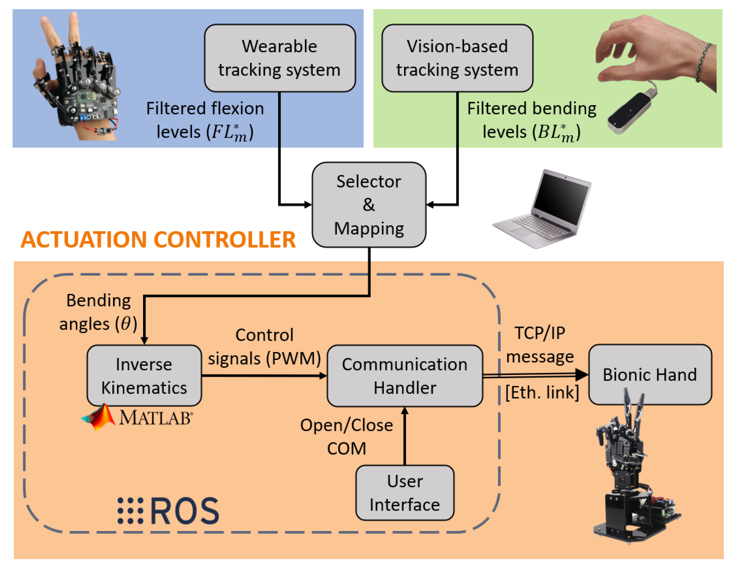
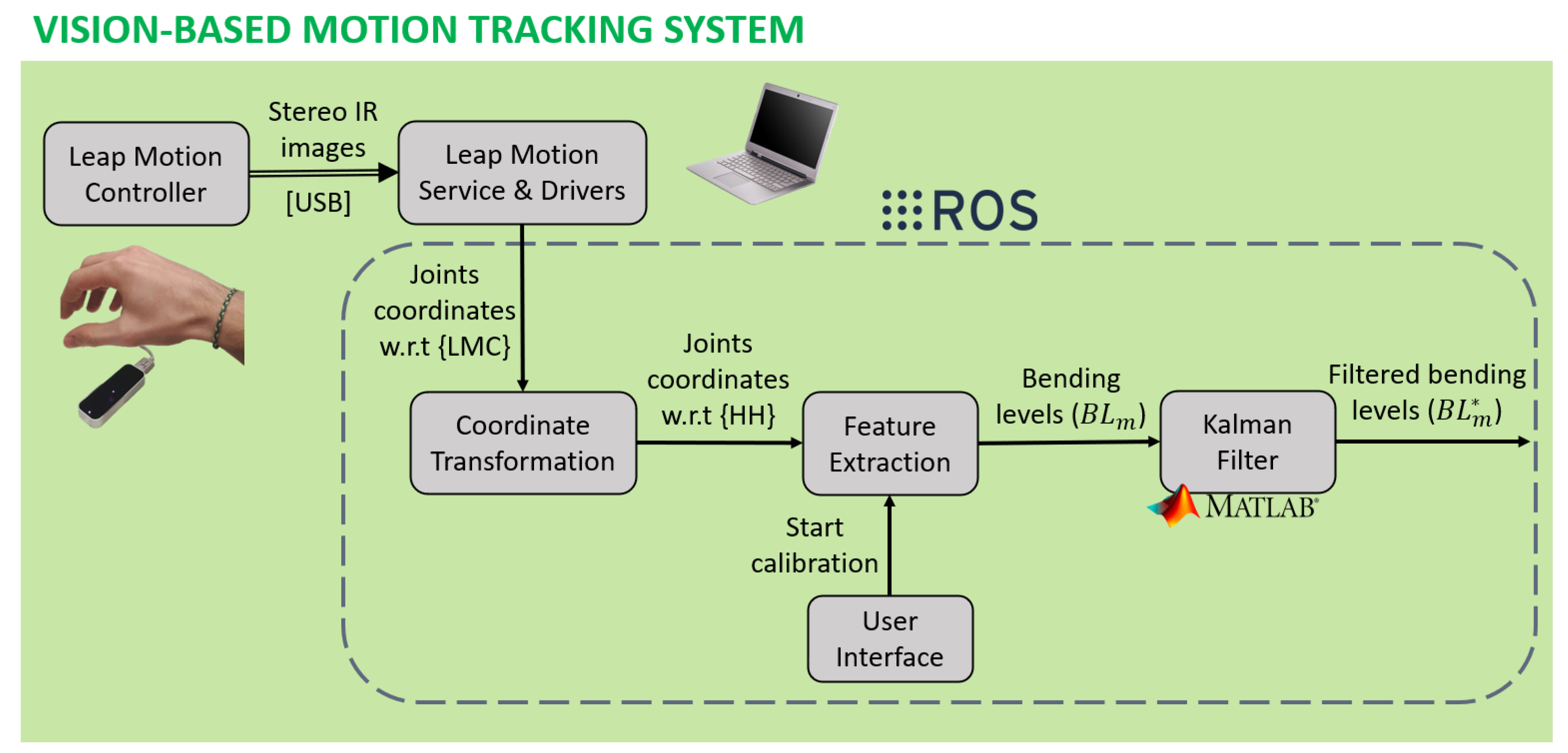
In this section, it is shown how the teleoperation control methods are implemented using the wearable-glove-based and the vision-based tracking methods, respectively. As depicted in Figure 7, the actuation controller stage is the same for both teleoperation systems, while the distinctive stage is the motion tracking one.
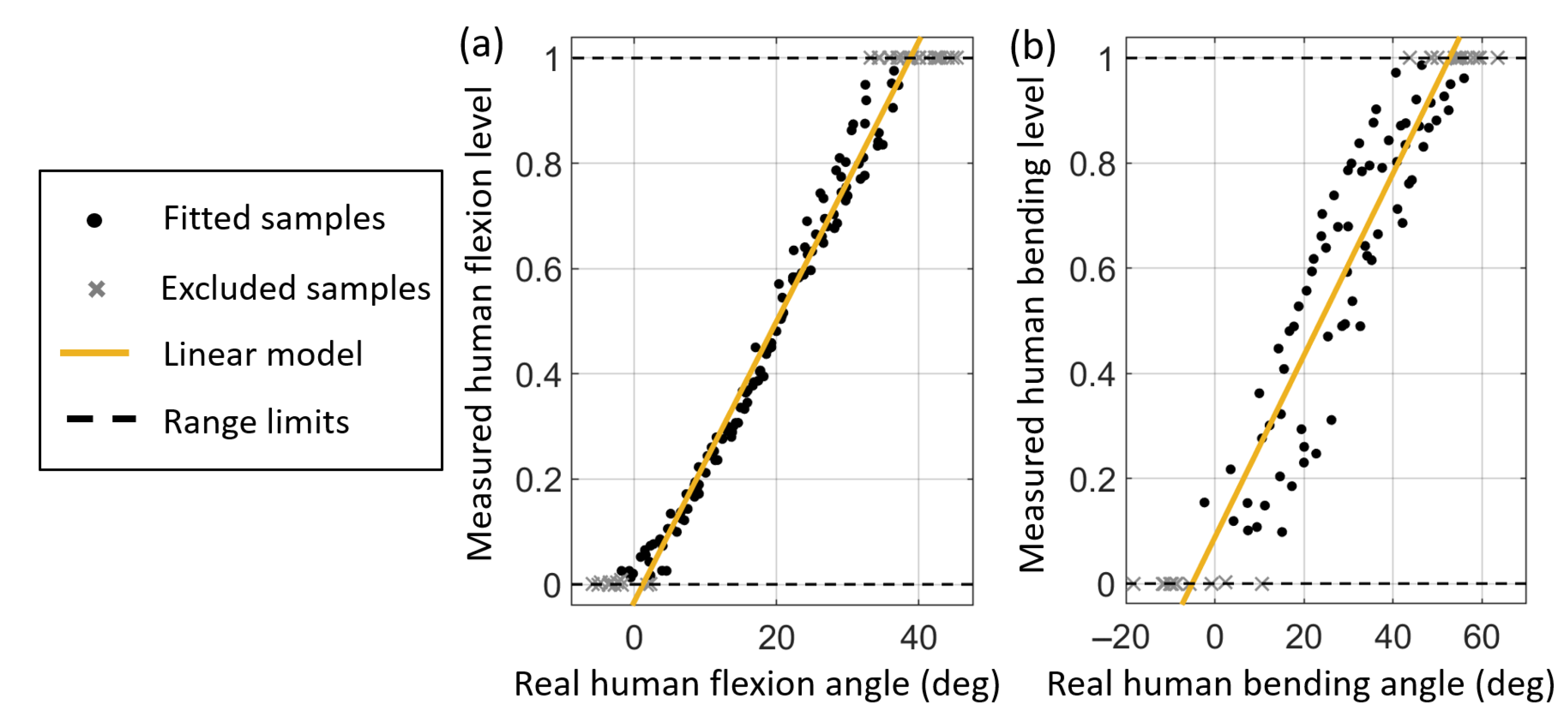
As described in Section 3.1 and 
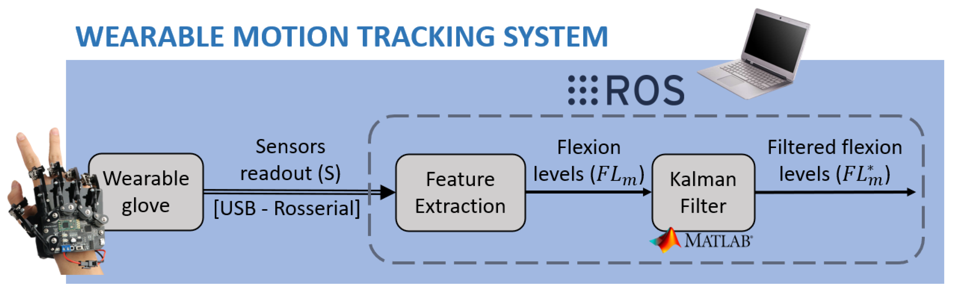
Section 3.2, each tracking system extracts for each finger one dimensionless human motion feature, ranging from 0 to 1, which represents the finger motion, namely the flexion level F L m * and the bending level B L m * , respectively. A prior step for teleoperation is mapping such a human feature to the robot feature, namely the robot bending angle θ . As the correspondence between human and robot gestures must be intuitively understandable and applicable by the user without any mental effort or long-time learning needed, the resulting movement of the robot must be highly semantically correlated to the human one, while considering the kinematic differences between human and robot structures. Benefiting from the conciseness and meaningfulness of the motion features extracted by the two tracking systems and from the underactuated mechanics of the bionic hand, a simple and intuitive mapping can be performed. The output of the utilised tracking system, whether F L m * in the case of the wearable system or B L m * in the case of the vision system, is multiplied for the bending angle range θ max measured during the bionic hand calibration described in Section 2.2.
θ = F L m * · θ max ( glove ) B L m * · θ max ( vision )
Once the bending angles are computed, an ROS node applies the inverse kinematics model synthesised in Section 2.2. To avoid a sudden change from one function to the other, and thus instability, the average value of the bending angle in the last 40 frames θ ¯ 40 (moving average on 1 second) was used to improve robustness. Only if the angle θ deviates from θ ¯ 40 for more than 1 % of the bending angle Range Of Motion (ROM), the direction changes are detected. Then, according to the current value of the direction (extension or flexion), the corresponding inverse kinematic function ( I K E and I K F , respectively) is applied to θ in order to obtain the motor control signal value P W M . The details of the implemented inverse kinematics algorithm are summarised in Algorithm 1.
Then, the communication handler node packs the control signals in a message characterised by a proper TCP/IP format and sends it to the bionic hand through an Ethernet link. Control messages are unpacked by the bionic hand processor, and the motors are driven consequently. A user interface manages the opening and closing of the communication link according to the user’s will. The user’s input is delivered through a keyboard and a mouse.
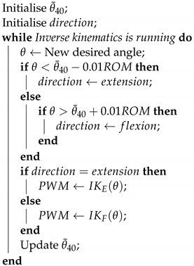
Algorithm 1: Inverse kinematics modelling of the underactuated bionic hand.
Robotics 11 00061 i001

5. Experimental Setup

In this section, three experiments are designed to estimate the ROM of the human finger angle to which the two tracking systems are respectively sensitive, evaluate the accuracy, and compare the usability of the two implemented teleoperation systems. Firstly, the system setup employed for the first and second experiments is described. Then, the protocol and evaluation metrics of the three experiments are explained.

5.1. System Setup

The first and the second experiments were designed to estimate the ROM of the human finger angle to which the two tracking systems are sensitive and to assess the accuracy of the two systems, respectively. This paper is focused on the results for the index finger motion. During the data acquisition part of the experiments, a human operator controlled the bionic hand through the developed systems. Meanwhile, two sets of optical markers were used to measure the resulting bending angle θ of the bionic hand (see Section 2.2 for the definition) and the ground truth of the human finger angle used to control the system, namely the real human flexion angle, φ r e a l (see Section 3.1 for the definition of flexion angle used in this work), for the wearable system and the real human bending angle, and β r e a l (see Section 3.2 for the definition of human finger bending angle), for the vision system.
As illustrated in Figure 8a, one marker was located on the side of the bionic hand index fingertip and three markers were placed on the side of the hand rigid case to define a 3D local reference frame. The MCP joint position was measured employing a pointing probe as the one shown in Figure 2d, using the same method described in Section 2.2 for the bionic hand calibration. Positioning possibilities concerning the human hand were limited by the wide space covered by the glove. In this case, five markers were used, as shown in Figure 8b: one on the fingertip side, one on the PIP joint side, one on the MCP joint side, one on the second Metacarpal Bone (SM) in correspondence with the styloid process, and on the Radial Styloid Process (RAD). The MCP, SM, and RAD were used to define a local reference frame. The MCP and PIP were used to measure the flexion angle, while the MCP and TIP where used to compute the bending angle. In both cases, a method similar to the one used by the vision-based method to retrieve the bending angle, described in Section 3.2, was implemented. Figure 8c,d show how the markers were integrated when using the glove-based and the LMC-based methods, respectively. The NDI optical tracking system, already used in Section 2.2, was employed to measure the 3D coordinates of the markers.

5.2. Protocol and Performance Metrics

5.2.1. Human Hand Range of Motion Experiment

The human angle measured by the ground truth tracking system, whether φ r e a l or β r e a l , is not directly comparable to the bionic hand bending angle θ , given the different ROM. A prior step to assess the accuracy of the teleoperation systems was the estimation of the human ROM that characterises the two human-hand-tracking systems, in order to normalise the measured angles, obtaining the dimensionless variables real human flexion level, F L h , and real human bending level, B L h , for the glove-based and vision-based systems, respectively. Such a variable can be compared to the robotic bending level B L r , that is θ normalised for its own range, that was measured during the bionic hand calibration in Section 2.2. Given the difficulty of precisely recording the poses that are associated with the human fingers limited by the tracking systems, an estimation of the human range was instead needed for each system.
To estimate the human ROM, a static calibration procedure was performed on each tracking system. Several ground truth human angles, homogeneously distributed in the ROM, were measured through the markers, and at the same time, the human flexion level F L m * and the human bending level B L m * measured and filtered by the tracking systems were recorded. Moreover, the robotic bending level resulting from the teleoperation mapping was also measured, to be used later in the accuracy experiment.
Four complete calibration cycles were obtained for each tracking system. The linear function that best fits the cycles (excluding saturation samples) was computed through least-squares linear regression. Such a function is assumed to be the ideal characteristic of the tracking system. This approximation is the most optimistic one, given that it minimises the distance of the samples from the ideal behaviour. The φ r e a l and β r e a l values that, according to the ideal characteristic, should correspond to the minimum and maximum F L m * and B L m * , were considered as the human range limits.

5.2.2. Accuracy Performance Comparison Experiment

To evaluate and compare the accuracy performance of the two implemented teleoperation control frameworks, three kinds of error were investigated during the second teleoperation experiment, in both static and dynamic scenarios, namely the ones listed and computed as follows and shown in Figure 9:
  • Overall teleoperation control accuracy error:
    ε t e l e , g l o v e = F L h B L r ε t e l e , v i s i o n = B L h B L r
  • Human hand motion tracking accuracy error:
    ε t r a c k , g l o v e = F L h F L m * ε t r a c k , v i s i o n = B L h B L m *
  • Bionic hand actuation control accuracy error:
    ε a c t , g l o v e = F L m * B L r ε a c t , v i s i o n = B L m * B L r
The static accuracy assessment was performed on the data acquired for the human ROM estimation experiment described in Section 5.2.1. Furthermore, both human and robotic finger angles were normalised for the respective ROM to obtain the comparable dimensionless features. For each kind of error, the couple of variables determining the error were compared assessing their calibration cycles. For each couple, the real static characteristic was found by fitting polynomials or rational functions on the samples through least-squares regression. The adjusted R-squared ( R a d j 2 ) metric was used to set the polynomials’ degree to choose the best fitting with the minimum function complexity. Then, for each couple, two error metrics were computed as follows:
  • Nonlinearity: illustrates the maximum distance between the real characteristic and the ideal one (output equal to input);
  • Hysteresis: represents the maximum distance between the two curves that compose the hysteresis cycle.
In the dynamic experiment, the human operator performed six different sinusoidal movements. In each movement, the frequency was qualitatively set by the operator to low (<0.4 Hz) or high (>0.4 Hz), while the amplitude was set to small (40% of B L r ROM explored), medium (60% of B L r ROM explored), or large ( B L r reaches saturation). For each movement, the variables that determine the aforementioned errors were recorded at 40 Hz, which is equal to the sampling frequency of the teleoperation systems. For each couple of variables, the signals corresponding to the same recording were synchronised by compensating the frame lag underlined by the cross-correlation. The distance between the signals was extracted as a metric of dynamic accuracy, computed as the Root-Mean-Squared Error (RMSE):
RMSE = 1 N i = 1 N x i y i 2
where N is the number of samples and x i and y i are the ith samples of the two signals, respectively. Moreover, the computed lag in the case of the overall teleoperation systems was used as a metric of the mean overall delay.

5.2.3. User Demonstration Experiment

To further verify and compare the feasibility and performance of the two frameworks in performing both power and precision grasp tasks, a user demonstration experiment was designed and implemented. In this experiment, 6 users were invited to perform the grasping task, and all of them were right-handed, in good health condition, and had no motor deficiency. The detailed experimental setup and steps are given as follows.
Material: As shown in Figure 10a, 4 objects were selected for grasping and divided into two groups: power grasp and precision grasp [2,33]. Each group required a different grasping posture: Object 1 (a parallelepiped, large-diameter power grasp), Object 2 (a cork stopper, tripod precision grasp), Object 3 (a cylinder, medium wrap power grasp), and Object 4 (a soft cube, quadpod precision grasp). Note that Object 2 and Object 4 belong to the precision grasp group and had to be grasped with only the bionic hand fingertips, without touching the palm. Following the completion of each experiment, each user was asked to complete a NASA TLX [34] questionnaire to assess their perceived workload.
Tasks: As shown in Figure 10b, the bionic hand was fixed to a table, and the user sat in front of it. The user approached the bionic hand with an object in his or her left hand and then performed the bionic hand grasp. Then, once the user was confident enough, he or she left the object in the robotic hand, which in turn held the object for 5 s, indicating that the grasp was successful. If the object fell or touched the palm (only for the precision grasp), the trial was deemed a failure. Each user was asked to perform 6 trials with the glove and vision-tracking methods for each object. Hence, 144 trials were performed for each method.

6. Results

This section gives the results of the designed experiments in the previous section, including the human hand range of motion estimation, the accuracy performance comparison, and the user demonstration results.

6.1. Human Hand Range of Motion Estimation Results

Four complete calibration cycles were measured for each system. There were 152 static poses obtained while using the wearable system, 56 of which related to extension, 52 to flexion, and 44 to saturation. As regards the vision-based system, one calibration cycle was excluded because it was affected by markers’ occlusion, thus obtaining 96 static poses, 33 of which related to extension, 34 to flexion, and 27 to saturation.
Figure 11 shows for each teleoperation system the fitting result of linear regression and the fitted samples. The resulting ROM was [ 1.22 ° ; 38.8 ° ] for φ r e a l (Figure 11a) when the operator used the glove and [ 5.09 ° ; 52.7 ° ] for β r e a l (Figure 11b) when the operator used the vision-based tracking method. As illustrated in the experiments of the estimation results, the human hand ROM varied when using the glove-based and vision-tracking-based methods, respectively. Hence, the normalisation for the human ROM is necessary to achieve intuitive and transparent teleoperation control.

6.2. Accuracy Performance Comparison Results

6.2.1. Overall Teleoperation Control Performance

Polynomial functions were adopted to find the static characteristics of the two overall teleoperation systems, which are the expressions that give B L r as a function of F L h or B L h . The fitting curves according to the adopted criteria are represented in Figure 12, together with the fitted samples. Table 1 summarises the fitting results and the resulting metrics about nonlinearity and hysteresis.
The wearable system is characterised by a linear region from 25% to 60% of the flexion level range, in accordance with the ideal characteristic. Nonlinearity is significantly present only outside this region, and it peaks at 89% of the range, which also corresponds to the peak of hysteresis. Fitting results in the case of the vision-based system were poorer because the dispersion of the samples was higher, hinting at lower behaviour predictability, mapping repeatability, and precision. The ideal characteristic runs from end to end of the hysteretic cycle and is completely detached from the two curves, implying that nonlinearity exists throughout the range. Nonlinearity and hysteresis peak at 20% and 26% of the range, respectively. As reported by Table 1, such behaviour gives worse error metrics.
The dynamic trials of the glove-based system shown in Figure 13a reported well-overlapped human and robot signals, except for a few missed peaks and a systematic vertical shift for the small-amplitude, high-frequency trial. The general trend, for this system, appears to be that movements with a lower frequency and amplitude are better transferred to the robot.
As regards the dynamic trials of the vision-based system, although the signals are highly correlated, they are less superimposed than in the wearable system case, and missing peaks are more visible. The small-amplitude, high-frequency trial was the worst case as for the glove system. In this case, the general trend appears to be that movements with both high frequency and high amplitude are more easily transferred to the robot. Based on the experimental results, the RMSE values reported in Table 2 are higher in the vision-based system in all six conditions, indicating a greater teleoperation error than in the glove case. Moreover, the vision-based system performed worse for slow and small movements, indicating that it is less suitable for fine and delicate operations.
Both static and dynamic trials showed that the accuracy of the vision-based teleoperation method was worse with respect to the glove-based one. On the contrary, there was no discernible systematic difference between the time delays that characterised the two systems, as reported by Table 2. In both cases, it was always under 0.5 s, with a mean value across the six trials of about 0.2 s, which is acceptable and does not compromise the teleoperation activity.

6.2.2. Human Hand Motion Tracking Performance

Polynomial functions were explored to find the static characteristics of the motion tracking stages of the two teleoperation systems, which are the expressions that give F L m * or B L m * as a function of F L h or B L h , respectively. The two datasets the functions were fitted on are the same employed in Section 6.1 to find the human angle range. According to the adopted criteria, the best-fitting curves had the same polynomial degrees as those used in Section 6.2.1 to model the characteristics of the two overall teleoperation systems. Indeed, a comparison of Figure 11a,b with Figure 12a,b reveals that the data distribution in the two tracking system stages was very similar to that in the two overall teleoperation systems. Table 3 summarises the fitting results and the resulting metrics about nonlinearity and hysteresis.
In both systems, the main differences from the overall teleoperation system case were a lower dispersion of the samples around the curves and a lower hysteresis below 20% of the human angle range. These distinctions resulted in better fitting and different metrics of nonlinearity and hysteresis, which were higher in the wearable system case and lower in the vision system case. Once again, samples’ dispersion, nonlinearity, and hysteresis in the vision system case were significantly worse.
Results from the dynamic part of the experiment agree with the static one. Table 4 illustrates the RMSE of the two teleoperation systems for each motion condition. In most of the conditions, the RMSE was slightly lower than the one computed for the overall teleoperation system. Once again, the vision-based system was affected by more evident missing peaks and greater RMSE values in all six conditions.
Both static and dynamic trials suggest that the vision-based tracking method is less accurate than the glove-based tracking method. Since the actuation control stage is the same for both systems, the lower accuracy of the vision-based method, underlined in Section 6.2.1, is solely due to the worse accuracy performance of the vision tracking stage.
Furthermore, given that in both developed teleoperation systems, the processing on the sensor data and the mapping complexity were reduced to the minimum, such worse performance can be related to the lower suitability of the LMC to be applied, with simple processing, as the controller for the teleoperation of a bionic hand. The reason may lie in the insufficient accuracy of the image processing procedure performed by the LMS while reconstructing the joint’s position. In the case of robot teleoperation in real scenarios, higher accuracy is advisable to grant safety and effectiveness to the control; thus, further research is needed to develop more robust algorithms for joint position estimation.

6.2.3. Bionic Hand Actuation Control Performance

Rational functions were explored to find the static characteristic of the actuation control stage, common to both teleoperation systems, that is the expressions that give B L r as a function of F L m * or B L m * . Table 5 summarises the degrees of rational function polynomials, the goodness-of-fit metrics, and the accuracy metrics. The RMSE is lower than the tracking stage one. Above 20% of the range, the curves are superimposed to the ideal behaviour. Nonlinearity is present only under 20% of the range. Samples’ dispersion is also higher in that region.
Then, Table 6 summarises the RMSE of the actuation control for each motion condition. In all conditions, the resulting robot path followed precisely the desired one defined by the measured human pose. The RMSE was always under 3% of the range.
Both static and dynamic results showed that the accuracy error of the actuation control system is not relevant for finger teleoperation. This was confirmed also by the high similarity between the results of the overall teleoperation and the ones related to motion tracking alone, underlined in Section 6.2.2. Therefore, the inverse kinematic model obtained through finger motion calibration, applied through a proper algorithm, proved to grant a generally accurate and reliable actuation control system, demonstrating improvements compared with the linear motion mapping approach.

6.3. User Demonstration Result

The screenshots in Figure 14a–d show the grasp scenario when using the vision-tracking-based method to grasp the objects, while Figure 14e–h are the screenshots when grasping the four objects utilising the glove-based one. As illustrated in these figures, the user can grasp different types of objects, using both the wearable glove and the vision-tracking-based methods, regardless of the power or precision grasp.
Results from the usability experiment in Table 7 show that the mean perceived workload was practically the same in the two systems. However, in the case of the glove, on average, the workload component due to global effort was perceived as higher, and the performance was perceived as higher as well. The success rate was high in both cases and slightly higher for the glove. Free user feedback was in line with questionnaire results: users felt the glove was better performing, but at the same time, less comfortable, causing greater effort.
The user demonstration results showed that the inaccuracy issue of the vision-based method does not compromise the teleoperation control; nevertheless, it has an impact on the teleoperation control performance. As regards the glove-based method, the user’s comfort is a critical issue. Although wearable devices are more accurate than vision-based ones, their applications may be limited if the user’s comfort is not prioritised, thus making vision-based methods become promising solutions. Therefore, to make wearable systems more competitive, mechanical hardware should be improved, taking user comfort into account.

7. Conclusions

This paper primarily compared two methods for teleoperation control of an underactuated bionic hand, namely wearable-glove-based and vision-tracking-based, respectively. First of all, the kinematics modelling of the bionic hand is a critical issue considering the underactuated and nonlinear characteristics of the bionic hand. In this paper, the calibration data from an external NDI tracking system were used to generate the kinematics model of the underactuated bionic hand, which was considered the ground truth. Then, how to achieve an intuitive motion mapping from the human hand to the bionic hand is another challenging issue. To solve this, the flexion and the bending angles of the human hand fingers were defined and measured by the two tracking systems, respectively. Besides, they were normalised for their own range and mapped to the bionic hand motion to achieve an intuitive teleoperation control. Furthermore, the accuracies of the two systems were compared, suggesting a higher performance of the glove-based method. Finally, the results of the accomplished precision and power grasp tasks in the user experiment demonstrated the feasibility of the proposed methods. Such an experiment revealed that the glove-based method grants a higher performance, but is also less comfortable and requires greater effort by the user. Future work will focus on integrating the developed teleoperation control frameworks and bionic hands into practical applications and scenarios.

Author Contributions

Conceptualisation, M.P., J.F., H.S. and E.D.M.; methodology, M.P., J.F. and H.S.; software, M.P. and J.F.; validation, M.P., J.F., Q.L. and E.I.; investigation, Q.L.; data curation, M.P. and J.F.; writing—original draft preparation, J.F., M.P., E.I. and Q.L.; writing—review and editing, J.F., M.P. and E.D.M.; supervision, G.F. and E.D.M.; project administration, E.D.M. All authors have read and agreed to the published version of the manuscript.

Funding

This research received no external funding.

Informed Consent Statement

Informed consent was obtained from all subjects involved in the study.

Data Availability Statement

Not applicable.

Conflicts of Interest

The authors declare no conflict of interest.

References

  1. Bayrak, A.; Bekiroglu, E. Bionic hand: A brief review. J. Bionic Mem. 2022, 2, 37–43. [Google Scholar] [CrossRef]
  2. Nikafrooz, N.; Leonessa, A. A Single-Actuated, Cable-Driven, and Self-Contained Robotic Hand Designed for Adaptive Grasps. Robotics 2021, 10, 109. [Google Scholar] [CrossRef]
  3. Piazza, C.; Simon, A.M.; Turner, K.L.; Miller, L.A.; Catalano, M.G.; Bicchi, A.; Hargrove, L.J. Exploring augmented grasping capabilities in a multi-synergistic soft bionic hand. J. Neuroeng. Rehabil. 2020, 17, 116. [Google Scholar] [CrossRef] [PubMed]
  4. Hinwood, D.; Herath, D.; Goecke, R. Towards the design of a human-inspired gripper for textile manipulation. In Proceedings of the 2020 IEEE 16th International Conference on Automation Science and Engineering (CASE), Hong Kong, China, 20–21 August 2020; pp. 913–920. [Google Scholar]
  5. Knoop, E.; Bächer, M.; Wall, V.; Deimel, R.; Brock, O.; Beardsley, P. Handshakiness: Benchmarking for human–robot hand interactions. In Proceedings of the 2017 IEEE/RSJ International Conference on Intelligent Robots and Systems (IROS), Vancouver, BC, Canada, 4–28 September 2017; pp. 4982–4989. [Google Scholar]
  6. Said, S.; Boulkaibet, I.; Sheikh, M.; Karar, A.S.; Alkork, S.; Naït-Ali, A. Machine-learning-based muscle control of a 3d-printed bionic arm. Sensors 2020, 20, 3144. [Google Scholar] [CrossRef] [PubMed]
  7. Controzzi, M.; Cipriani, C.; Carrozza, M.C. Design of artificial hands: A review. Hum. Hand Inspir. Robot. Hand Dev. 2014, 95, 219–246. [Google Scholar]
  8. Grebenstein, M.; Chalon, M.; Hirzinger, G.; Siegwart, R. Antagonistically driven finger design for the anthropomorphic DLR hand arm system. In Proceedings of the 2010 10th IEEE-RAS International Conference on Humanoid Robots, Nashville, TN, USA, 6–8 December 2010; pp. 609–616. [Google Scholar]
  9. Kashef, S.R.; Amini, S.; Akbarzadeh, A. Robotic hand: A review on linkage-driven finger mechanisms of prosthetic hands and evaluation of the performance criteria. Mech. Mach. Theory 2020, 145, 103677. [Google Scholar] [CrossRef]
  10. He, B.; Wang, S.; Liu, Y. Underactuated robotics: A review. Int. J. Adv. Robot. Syst. 2019, 16, 1729881419862164. [Google Scholar] [CrossRef] [Green Version]
  11. Heinemann, F.; Puhlmann, S.; Eppner, C.; Élvarez-Ruiz, J.; Maertens, M.; Brock, O. A taxonomy of human grasping behaviour suitable for transfer to robotic hands. In Proceedings of the 2015 IEEE International Conference on Robotics and Automation (ICRA), Seattle, WA, USA, 26–30 May 2015; pp. 4286–4291. [Google Scholar]
  12. Zang, W.; Yao, P.; Song, D. Standoff tracking control of underwater glider to moving target. Appl. Math. Model. 2022, 102, 1–20. [Google Scholar] [CrossRef]
  13. Tavakoli, M.; Enes, B.; Santos, J.; Marques, L.; de Almeida, A.T. Underactuated anthropomorphic hands: Actuation strategies for a better functionality. Robot. Auton. Syst. 2015, 74, 267–282. [Google Scholar] [CrossRef]
  14. Li, R.; Wang, H.; Liu, Z. Survey on Mapping Human Hand Motion to Robotic Hands for Teleoperation. IEEE Trans. Circuits Syst. Video Technol. 2022, 32, 2647–2665. [Google Scholar] [CrossRef]
  15. Fu, J.; Zhang, J.; She, Z.; Ovur, S.E.; Li, W.; Qi, W.; Su, H.; Ferrigno, G.; De Momi, E. Whole-body Spatial Teleoperation Control of a Hexapod Robot in Unstructured Environment. In Proceedings of the 2021 6th IEEE International Conference on Advanced Robotics and Mechatronics (ICARM), Chongqing, China, 3–5 July 2021; pp. 93–98. [Google Scholar]
  16. Fang, B.; Guo, D.; Sun, F.; Liu, H.; Wu, Y. A robotic hand-arm teleoperation system using human arm/hand with a novel data glove. In Proceedings of the 2015 IEEE International Conference on Robotics and Biomimetics (ROBIO), Zhuhai, China, 6–9 December 2015; pp. 2483–2488. [Google Scholar]
  17. Saggio, G.; Bizzarri, M. Feasibility of teleoperations with multi-fingered robotic hand for safe extravehicular manipulations. Aerosp. Sci. Technol. 2014, 39, 666–674. [Google Scholar] [CrossRef]
  18. Liu, H. Exploring human hand capabilities into embedded multifingered object manipulation. IEEE Trans. Ind. Infor. 2011, 7, 389–398. [Google Scholar] [CrossRef]
  19. Hu, X.; Baena, F.R.; Cutolo, F. Rotation-constrained optical see-through headset calibration with bare-hand alignment. In Proceedings of the 2021 IEEE International Symposium on Mixed and Augmented Reality (ISMAR), Bari, Italy, 4–8 October 2021; pp. 256–264. [Google Scholar]
  20. Xiong, X.; Manoonpong, P. Resistance-as-needed (RAN) control for a wearable and soft hand exoskeleton. Gait Posture 2020, 81, 398–399. [Google Scholar] [CrossRef]
  21. Dipietro, L.; Sabatini, A.M.; Dario, P. A survey of glove-based systems and their applications. IEEE Trans. Syst. Man. Cybern. Part C Appl. Rev. 2008, 38, 461–482. [Google Scholar] [CrossRef]
  22. Diftler, M.A.; Culbert, C.; Ambrose, R.O.; Platt, R.; Bluethmann, W. Evolution of the NASA/DARPA robonaut control system. In Proceedings of the 2003 IEEE International Conference on Robotics and Automation (Cat. No. 03CH37422), Taipei, Taiwan, 14–19 September 2003; Volume 2, pp. 2543–2548. [Google Scholar]
  23. Almeida, L.; Lopes, E.; Yalçinkaya, B.; Martins, R.; Lopes, A.; Menezes, P.; Pires, G. Towards natural interaction in immersive reality with a cyber-glove. In Proceedings of the 2019 IEEE International Conference on Systems, Man and Cybernetics (SMC), Bari, Italy, 6–9 October 2019; pp. 2653–2658. [Google Scholar]
  24. Artal-Sevil, J.; Montañés, J.; Acón, A.; Domínguez, J. Control of a bionic hand using real-time gesture recognition techniques through Leap Motion Controller. In Proceedings of the 2018 XIII Technologies Applied to Electronics Teaching Conference (TAEE), Canary Island, Spain, 20–22 June 2018; pp. 1–7. [Google Scholar]
  25. Alimanova, M.; Borambayeva, S.; Kozhamzharova, D.; Kurmangaiyeva, N.; Ospanova, D.; Tyulepberdinova, G.; Gaziz, G.; Kassenkhan, A. Gamification of hand rehabilitation process using virtual reality tools: Using Leap Motion for hand rehabilitation. In Proceedings of the 2017 First IEEE International Conference on Robotic Computing (IRC), Taichung, Taiwan, 10–12 April 2017; pp. 336–339. [Google Scholar]
  26. Gierlach, D.; Gustus, A.; van der Smagt, P. Generating marker stars for 6D optical tracking. In Proceedings of the 2012 4th IEEE RAS & EMBS International Conference on Biomedical Robotics and Biomechatronics (BioRob), Rome, Italy, 24–27 June 2012; pp. 147–152. [Google Scholar]
  27. Chevtchenko, S.F.; Vale, R.F.; Macario, V. Multi-objective optimization for hand posture recognition. Expert Syst. Appl. 2018, 92, 170–181. [Google Scholar] [CrossRef]
  28. Su, H.; Zhang, J.; Fu, J.; Ovur, S.E.; Qi, W.; Li, G.; Hu, Y.; Li, Z. Sensor Fusion-based Anthropomorphic Control of Under-Actuated Bionic Hand in Dynamic Environment. In Proceedings of the 2021 IEEE/RSJ International Conference on Intelligent Robots and Systems (IROS), Prague, Czech Republic, 23–27 October 2022; pp. 2722–2727. [Google Scholar]
  29. Hornik, K.; Stinchcombe, M.; White, H. Multilayer feedforward networks are universal approximators. Neural Net. 1989, 2, 359–366. [Google Scholar] [CrossRef]
  30. Welch, G.; Bishop, G. An introduction to the Kalman filter. In Proceedings of the SIGGRAPH, Los Angeles, CA, USA, 6–11 August 1995; pp. 127–132. [Google Scholar]
  31. Lora-Millan, J.S.; Hidalgo, A.F.; Rocon, E. An IMUs-Based Extended Kalman Filter to Estimate Gait Lower Limb Sagittal Kinematics for the Control of Wearable Robotic Devices. IEEE Access 2021, 9, 144540–144554. [Google Scholar] [CrossRef]
  32. Lee, J.K.; Jeon, T.H.; Jung, W.C. Constraint-augmented Kalman filter for magnetometer-free 3D joint angle determination. Int. J. Control. Autom. Syst. 2020, 18, 2929–2942. [Google Scholar] [CrossRef]
  33. Feix, T.; Romero, J.; Schmiedmayer, H.B.; Dollar, A.M.; Kragic, D. The grasp taxonomy of human grasp types. IEEE Trans. Hum.-Mach. Syst. 2015, 46, 66–77. [Google Scholar] [CrossRef]
  34. Hart, S.G. NASA-task load index (NASA-TLX); 20 years later. In Proceedings of the Human Factors and Ergonomics Society Annual Meeting, San Francisco, CA, USA, 16–20 October 2016; Sage publications Sage CA: Los Angeles, CA, USA, 2006; Volume 50, pp. 904–908. [Google Scholar]
Figure 1. Human hand structure and the underactuated bionic hand mechanical structure. (a) Scheme of human hand joints’ classification. Distal Interphalangeal joint (DIP), Proximal Interphalangeal joint (PIP), Metacarpophalangeal joint (MCP), Interphalangeal joint (IP). (b) Components and mechanical structure of the underactuated bionic hand.
Robotics 11 00061 g001
Figure 2. Experimental setup for measuring the bending angle. (a) Overview setup of the system. (b) Positions of markers on the thumb. (c) Positions of markers on the index finger. (d) Illustration of the pointing probe used to calculate the MCP position.
Robotics 11 00061 g002
Figure 3. Data collection for calibration and kinematics modelling of the underactuated bionic hand fingers. (ae) represent data for the thumb, index, middle, ring, and pinkie respectively, including both the extension and flexion process.
Robotics 11 00061 g003
Figure 4. Components of the wearable-glove-based motion tracking framework.
Robotics 11 00061 g004
Figure 5. Definition of the flexion angle when using the wearable glove: minimum (a) and maximum (b) flexion angles. Reference systems (c) and defined bending angle (d) in the vision-based method.
Robotics 11 00061 g005
Figure 6. Components of the vision-based motion tracking system.
Robotics 11 00061 g006
Figure 7. Frameworks of the two implemented teleoperation systems. As the actuation control part is the same in both cases, a single diagram is used, but only one tracking system is used at a time.
Robotics 11 00061 g007
Figure 8. Markers’ positioning during the accuracy testing experiment. (a) Markers positions on the bionic hand. (b) Markers positions on the human hand. (c) Human hand with markers in the glove-based method. (d) Human hand with markers in the vision-based tracking method.
Robotics 11 00061 g008
Figure 9. Illustration of the errors in the comparison experiments, including the overall teleoperation error, human hand motion tracking error, and bionic hand actuation control error.
Robotics 11 00061 g009
Figure 10. User study experimental setup. (a) Objects for the grasping tasks in the user study. (b) User demonstration experimental setup.
Robotics 11 00061 g010
Figure 11. Human hand range of motion estimation results. (a) Glove-based method. (b) Leap Motion vision-tracking system method.
Robotics 11 00061 g011
Figure 12. Static testing of overall teleoperation control. (a,b) are the fitting results of the glove and vision-tracking system. (c,d) and the nonlinearity and hysteresis of the glove and vision-tracking system.
Robotics 11 00061 g012
Figure 13. Dynamic testing of overall teleoperation control under 6 different conditions. (a) Glove-based results. (b) Vision-tracking-based results.
Robotics 11 00061 g013
Figure 14. User demonstration results of the implemented teleoperation control frameworks. Figures from (ad) represent the four grasping types based on vision tracking teleoperation. Figures (eh) are the four grasping types based on wearable glove teleoperation.
Robotics 11 00061 g014
Table 1. Fitting results and error metrics of the two implemented teleoperation systems.
SystemDirectionPolynomial DegreeRMSE R a d j 2 NonlinearityHysteresis
WearableFlexion5th0.02250.99311.1%14.6%
Extension2nd0.02730.989
VisionFlexion1st0.05550.96420.0%27.0%
Extension2nd0.06090.934
Table 2. Mean delay in ms and RMSE of the two teleoperation systems for each motion condition. The terms large, medium, and small refer to the signal amplitude, while low and high refer to the signal frequency.
SystemLarge-LowMedium-LowSmall-LowLarge-HighMedium-HighSmall-High
Delay (ms)Wearable400225125175175150
Vision3503250250225150
RMSEWearable4.01%3.40%2.80%5.67%4.44%7.33%
Vision8.72%6.56%8.51%6.42%7.19%12.6%
Table 3. Fitting results and error metrics of the two implemented tracking stages.
SystemDirectionPolynomial DegreeRMSE R a d j 2 NonlinearityHysteresis
WearableFlexion5th0.01840.99512.5%16.2%
Extension2nd0.02520.992
VisionFlexion1st0.05480.963118.0%25.1%
Extension2nd0.05900.946
Table 4. Tracking systems’ dynamic performance comparison: for each motion condition, the RMSE is reported as a percentage of the human finger ROM. The terms large, medium, and small refer to the signal amplitude, while low and high refer to the signal frequency.
SystemLarge-LowMedium-LowSmall-LowLarge-HighMedium-HighSmall-High
Wearable3.20%3.05%2.23%3.89%4.71%7.50%
Vision8.14%6.62%7.44%5.70%7.01%12.5%
Table 5. Fitting results and error metrics of the implemented actuation control system.
DirectionPolynomial DegreeRMSE R a d j 2 NonlinearityHysteresis
Flexion3rd/4th0.01390.9984.11%7.37%
Extension3rd/1st0.01320.999
Table 6. Actuation control stage dynamic performance: for each motion condition, the RMSE is reported as a percentage of the bionic finger ROM. The terms large, medium, and small refer to the signal amplitude, while low and high refer to the signal frequency.
Large-LowMedium-LowSmall-LowLarge-HighMedium-HighSmall-High
1.52%1.27%0.78%2.03%1.68%3.00
Table 7. Comparison result from the user demonstration experiment. The success rate and the average adjusted ratings of workload indexes considered by the NASA TLX questionnaire are reported. The total workload is the sum of the adjusted ratings and can range from 0 to 100.
Evaluation IndexWearable SystemVision System
Mental demand8.47.9
Physical demand7.17.2
Temporal demand3.13.8
Performance3.55.9
Effort129.5
Frustration4.73.5
Total workload38.8/10037.8/100
Success rate 98.6 % 96.5 %
Publisher’s Note: MDPI stays neutral with regard to jurisdictional claims in published maps and institutional affiliations.

