Communication

Multi-Layered Carbon-Black/Elastomer-Composite-Based Shielded Stretchable Capacitive Sensors for the Underactuated Robotic Hand

1
Department of Mechanical Engineering, The University of Heilongjiang, Harbin 150080, China
2
Department of Mechanical and Mechatronics Engineering, The University of Auckland, Auckland 1010, New Zealand
*
Author to whom correspondence should be addressed.
Robotics 2022, 11(3), 58; https://doi.org/10.3390/robotics11030058
Submission received: 8 April 2022 / Revised: 4 May 2022 / Accepted: 5 May 2022 / Published: 7 May 2022
(This article belongs to the Section Sensors and Control in Robotics)

Abstract

:
Soft and flexible strain sensors are becoming popular for many robotic applications. This article presents a stretchable capacitive sensor by combining a conductive filler of carbon black with elastomers and implementing shielding to reduce parasitic interference, applied to an underactuated robotic hand. Sensors with different configurations were explored. The results show that a shield introduced to the sensor does have some mitigation effect on external interference. Two sensor configurations were explored: longitudinal interdigitated capacitive (LIDC) sensor, where the interdigitated fingers lie along the same axis as the strain, and transverse interdigitated capacitive (TIDC) sensor, where the interdigitated fingers are orthogonal to the strain direction. The LIDC configuration had better performance than TIDC. The fabricated two-layered LIDC sensor had a gage factor of 0.15 pF/mm and the rates of capacitive creep of 0.000667 pF/s and 0.001 pF/s at loads of 120 g and 180 g, respectively. The LIDC sensors attached to an underactuated robotic hand demonstrate the sensors’ ability to determine the bending angles of the proximal interphalangeal (PIP) and metacarpophalangeal (MCP) joints.

1. Introduction

Humans can recognize an object’s physical and geometrical properties, using tactile information from hands with an accuracy as high as 94% in approximately 5 s [1,2]. Robots also need the human ability to adapt to changing situations and continuously sense the surrounding environment [3]. By equipping haptic or tactile sensors on robotic hands, robots can perform tactile object recognition, which helps them recognize surrounding objects, realizing various human–computer interactions [4].
The underactuated robotic hands (URH) have the advantages of energy savings, material savings, space savings, and being lighter, making them widely studied [5,6,7,8]. Despite the benefits of URH, there has been relatively limited use of such systems in haptic applications. It is due to the kinematic uncertainty of finger behavior after encountering unknown objects in arbitrary poses [9], and hence, the use of sensors to provide information about the joints allows the general recognition of object size and shape.
To solve the kinematic uncertainty, it becomes necessary to mount sensors on the hand, determining the turning or bending of each joint. In many instances, due to limited space and weight, traditional position sensors are not suitable for the URH. There were attempts to use solid air pressure sensors embedded in a 3D printed soft robotic hand for prosthetic application [10], but this required the robotic hand to be designed to accommodate this embedded sensor. Hence, the use of stretchable sensors made from elastomers, exhibiting promising applications, has been widely explored [11,12,13,14], as it can easily be retrofitted to any existing robotic hand. However, because of the inherent viscoelasticity of the matrix phase, polymer composites are prone to creep and stress relaxation, making it a challenge when considering composites for long-term applications [15,16,17,18,19]. Therefore, when selecting a sensor to meet the requirements of an application, the characteristics of different stretchable sensors need to be considered. Generally, piezoelectric sensors are suitable for sensing dynamic signals. Piezoresistive sensors have the advantages of easy fabrication [20], despite the disadvantages of nonlinear response, stress relaxation, and hysteresis. Capacitors are sensitive and precise, but parasitic capacitance and susceptibility to the environment are serious issues that are difficult to solve. In addition, the creep-recovery response of stretchable capacitors has to be considered in applications [21,22,23].
For the application of grasping and classifying objects by the URH, since the hand is often kept in a constant position, stress relaxation of sensors made from elastomer seriously affects the accuracy and speed of the application. It is critical for the URH because it is impossible to know which sensors are in a stress–relaxation state. On the other hand, the creep-recovery response was reported in the literature [24,25], in which the load remains constant, but the elongation of the elastomeric substrate continues to change. However, compared with stress relaxation, the creep–recovery response is not a problem for applying grasping and object shape classification. Therefore, stretchable capacitive sensors are the choice of this research.
Environmental interferences, such as parasitic capacitance, pose drawbacks for capacitive sensors [26]. Unfortunately, most research on stretchable capacitive sensors ignores these issues. Commonly, the shield wrapped around the signal path between the sensor and the input pin to the measuring device is an efficient way to reduce environmental interferences from affecting the capacitance measurements [27].
This article aims to demonstrate the technique to produce stretchable capacitive sensors assembled from elastic conductive thin films of carbon black and Ecoflex 00-30 composite that is retrofitted to a URH. The highly flexible architecture makes the sensors suitable for robotic hands, where the sensors are easily retrofitted to the back of the fingers. Soft, flexible sensors that can be strained up to 50% with good linearity and small hysteresis that can be retrofit into any URH are the main objectives. There have been many reports on the use of soft stretch sensors based on the piezoresistive effect using carbon-based materials, but they suffer high hysteresis [28]. It was reported that capacitive based stretchable sensor has small hysteresis [29] but it can be affected by external parasitic capacitance; hence this article explores the use of the shielded capacitive sensor in an attempt to reduce this effect. By using those stretchable capacitive sensors, the URH can provide bending information of its fingers, which will help the hand classify the shapes of the grasped objects. A shield is added to the capacitive sensor to reduce the impact of external interferences. In this article, the capacitive sensors formed with interdigitated fingers are used and are termed interdigitated capacitive (IDC) sensors. These sensors aim to provide information on the bending angles of each joint in the URH so that the size and general shape of the object being grasped by the URH can be estimated.

2. Materials and Methods

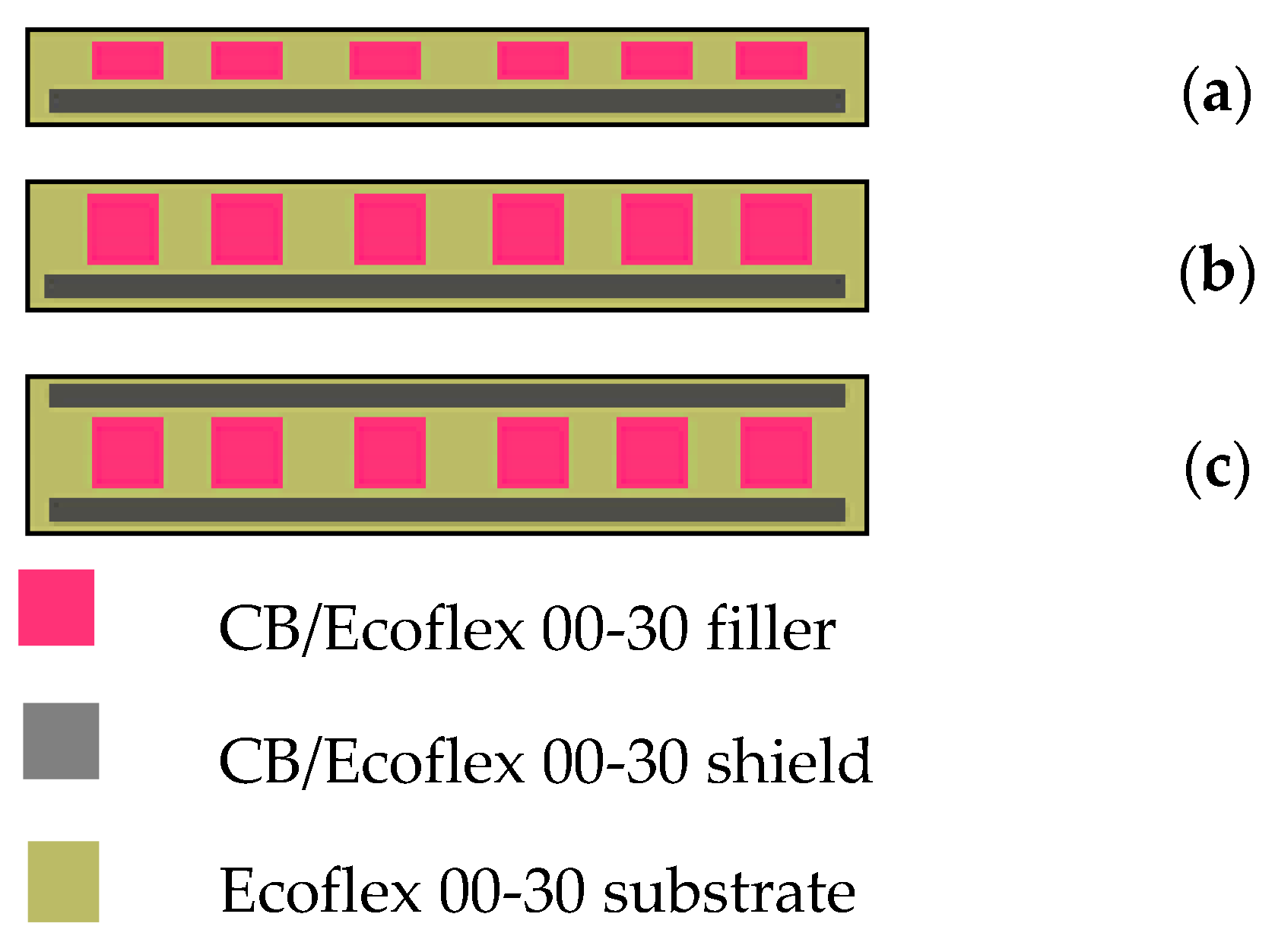
2.1. The Architecture of the Sensors

The IDC sensors can be arranged in two different configurations, i.e., longitudinal IDC (LIDC) and transverse IDC (TIDC) as shown in Figure 1. Figure 1a is the LIDC sensors where the IDC fingers lie in the same direction as the strain direction. Figure 1b is the TIDC, whose stretching direction is orthogonal to the IDC fingers. The IDC’s fingers were fabricated with Ecoflex 00-30 mixed with carbon black (CB). Ecoflex 00-30 was purchased from Smooth-On, Inc., and the CB (Vulcan XC 72) is from Fuel Cell Store. More details on the fabrication are presented in the next section.
The capacitance of a single pair of coplanar interdigitated electrodes can be calculated using the conformal mapping technique, as given by Equation (1) [29,30].
C p = 2 ε r ε 0 l π I n [ ( 1 + ω α ) + ( 1 + ω α ) 2 1   ]
where C p is the capacitance, and ε r   a n d   ε 0 are the relative permittivity of 2.8 [30] of the substrate material and the free space, respectively.   l is the length of the electrode, ω is the width of the electrode, and α is the half-gap between the electrodes.
The total capacitance at a zero strain of interdigitated capacitive strain sensor is calculated using Equation (2) [29,30].
C s = ( 2 n 1 ) C p
where C s is the capacitance of the IDC sensor at a 0% strain and n is the total number of the coplanar electrode.
The relative change in capacitance of the IDC sensor is expressed as Equation (3).
C p ( ε + Δ ε ) C p ( ε ) C p ( ε ) = C p ( ε + Δ ε ) C p ( ε ) 1 Δ ε C p ( ε ) / C p ( ε )
The gage factor (GF) represents the sensitivity of the strain sensors. It can be defined as the ratio of the relative change of capacitance of the IDC sensor to the corresponding strain, and it is expressed as
G F = ( C p ( ε + Δ ε ) C p ( ε ) ) / C p ( ε ) Δ ε C p ( ε ) / C p ( ε )
For an LIDC sensor, it stretches along the direction of l , and if it ignores the change in ω and α , the capacitance will increase with the strain, and the GF is
G F = 1 l
However, for a TIDC sensor, it stretches along the direction of α , and if it ignores the change in l and ω , the capacitance will reduce with strain and the GF is
G F = 2 ε r ε 0 l ω π C p α 2 [ ( 1 + ω α ) + ( 1 + ω α ) 2 1 ] ( 1 + 1 + ω α ( 1 + ω α ) 2 1 )
To understand the capacitance change and gage factor of the LIDC and TIDC sensors when they were stretched, a simulation was conducted. Both sensors are 30 mm in length but with only 1 finger pair, where the ω = 1   mm , α = 1   mm . Figure 2a shows that the LIDC sensor exhibits a linear behavior for the capacitance versus stretching compared to the TIDC sensor (Figure 2b). As the Poisson ratio of elastomer is high, the TIDC behavior is expected to be non-linear as shown in Figure 2b. In addition, the LIDC sensor has a constant GF with stretching but the TIDC sensor’s GF varies with stretching, which means that the LIDC sensor is more suitable for the robotic hand. Additionally, the TIDC sensor is wider than the LIDC, and making it narrower to fit the width of the finger will reduce its capacitance. Therefore, the LIDC sensor is fabricated for application in the URH.

2.2. The Material and Schematic of the Sensors

Among various stretchable sensors, polymeric composites filled with conductors, which combine appropriate electrical properties of the conductive fillers with excellent mechanical compliance of the flexible matrices, show a promising perspective [31,32]. Because of their low cost, excellent electrical conductivity, the potential for mass production, high chemical, and thermal stability, and inherent flexibility, carbon-based materials, such as carbon nanotubes (CNTs), graphene, and CB, have been extensively used as conductive fillers in wearable sensors [20,21,22,23]. Many commercially available polymeric materials, such as poly (dimethylsiloxane) (PDMS), Ecoflex polyurethane (PU), epoxy, polyvinylidene fluoride (PVDF), and polymethyl methacrylate (PMMA), have been used [33,34,35]. According to the previous studies [24,25], CNTs have a carcinogenic potential, and PDMS exhibits larger hysteresis characteristics when compared with Ecoflex under the same conditions. Therefore, Ecoflex 00-30 and CB were used as the sensors’ materials in this research.
To reduce the environmental interferences, a planar shield is added to the sensors. The shield coupling with the sensor helps to mitigate the electrical interference and parasitic capacitances [26]. Figure 3 exhibits some common arrangements of the shield. Figure 3a–c shows the cross section of the one-layer IDC sensor with one-layer shield (1L1S), two-layer IDC sensor with one-layer shield (2L1S), and two-layer IDC sensor in parallel with the two-layer shield (2L2S), respectively. The shield covers the complete IDC and is placed planarly beneath or on top of the sensors in Figure 1. In this application, the LIDC in the 1L1S and 2L1S arrangements were used because using the 2L2S arrangement will make the sensor too thick and increase the elastic resistance. Further, the LIDC configuration allows the sensors to be narrower and fit the URH’s fingers. Therefore, the LIDC sensors in the 1L1S arrangement are discussed in this research.

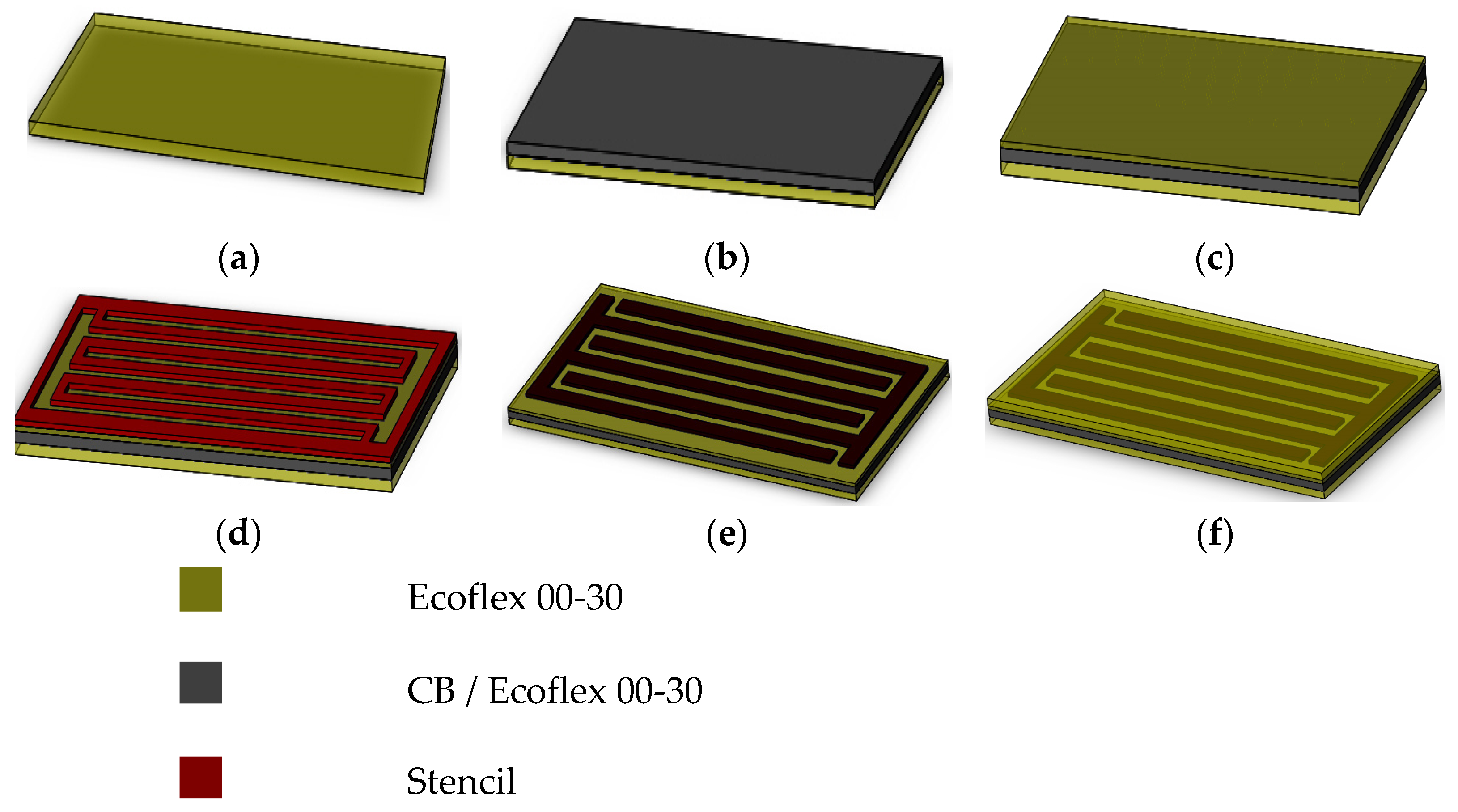
2.3. The Fabrication of the Sensors

Figure 4 presents the fabrication of the LIDC sensor as a 1L1S arrangement. An EcoflexTM 00-30 substrate was cast into a rectangular mold and then cured at 80 °C for an hour (Figure 4a). Next, the conductive filler was prepared by mixing CB of 50 nm particles size and Ecoflex 00-30 with a 1:9 weight ratio of CB and Ecoflex. The reason for choosing the ratio is because it can be completely cured [25] with reasonably low resistance (~10 kΩ/cm for 1 mm wide trace). With the aid of a mold, the mixture was deposited on the cured Ecoflex 00-30 (Figure 4b) and then left to cure in the oven at 80 °C overnight. This is the bottom shield layer. After that, another layer of Ecoflex 00-30 was deposited on top of the shield layer (Figure 4c) and then cured. Then a stencil was placed on it (Figure 4d), and the conductive mixture (CB and Ecoflex 00-30) was deposited and then doctor-bladed to form the IDC (Figure 4e). (Note: In the two-layer IDC arrangements, such as 2L1S and 2L2S, another layer of the conductive mixture is added after the first IDC layer is cured; hence the IDC fingers are twice the thickness of a one-layer IDC.) Finally, a protective layer of Ecoflex 00-30 was cast on top and cured at 80 °C (Figure 4f). Given the size of the fingers and maximized GF, the dimension of the IDC is l = 30   mm , ω = 0.8   mm and α = 0.4   mm , and this resulted in an overall size of 30 mm × 10 mm, which can fit the finger of the URH. The thickness of the shield and a one-layer IDC finger is 0.5 mm.

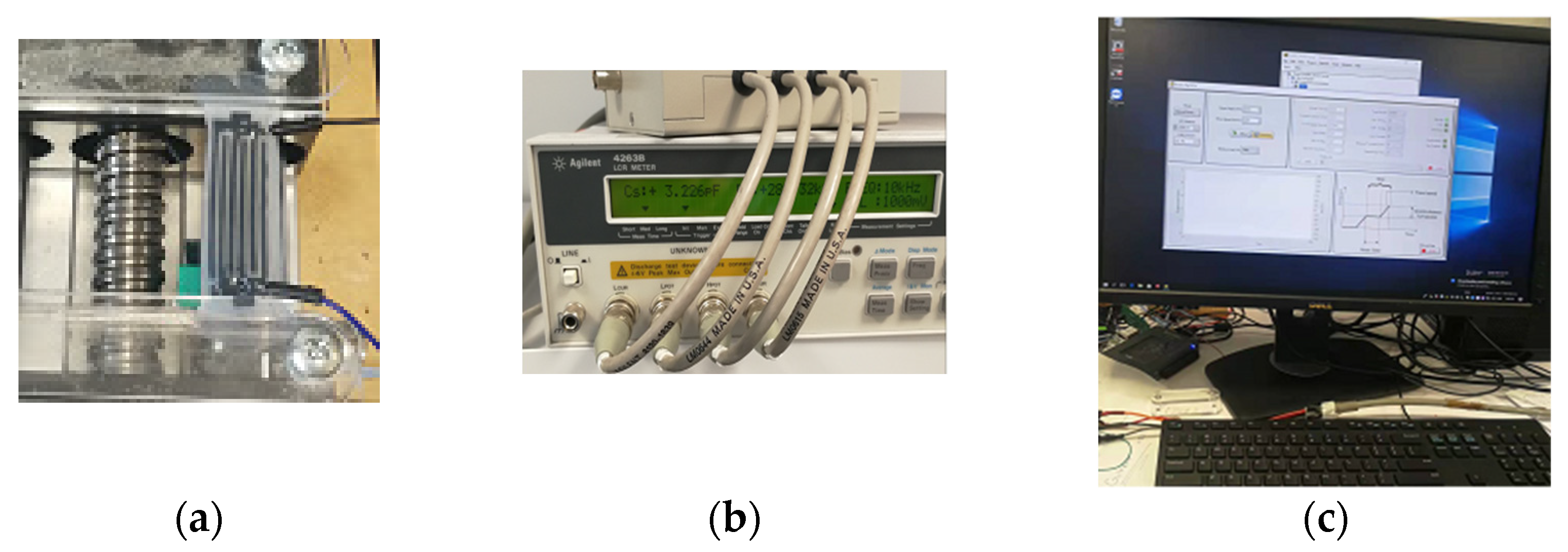
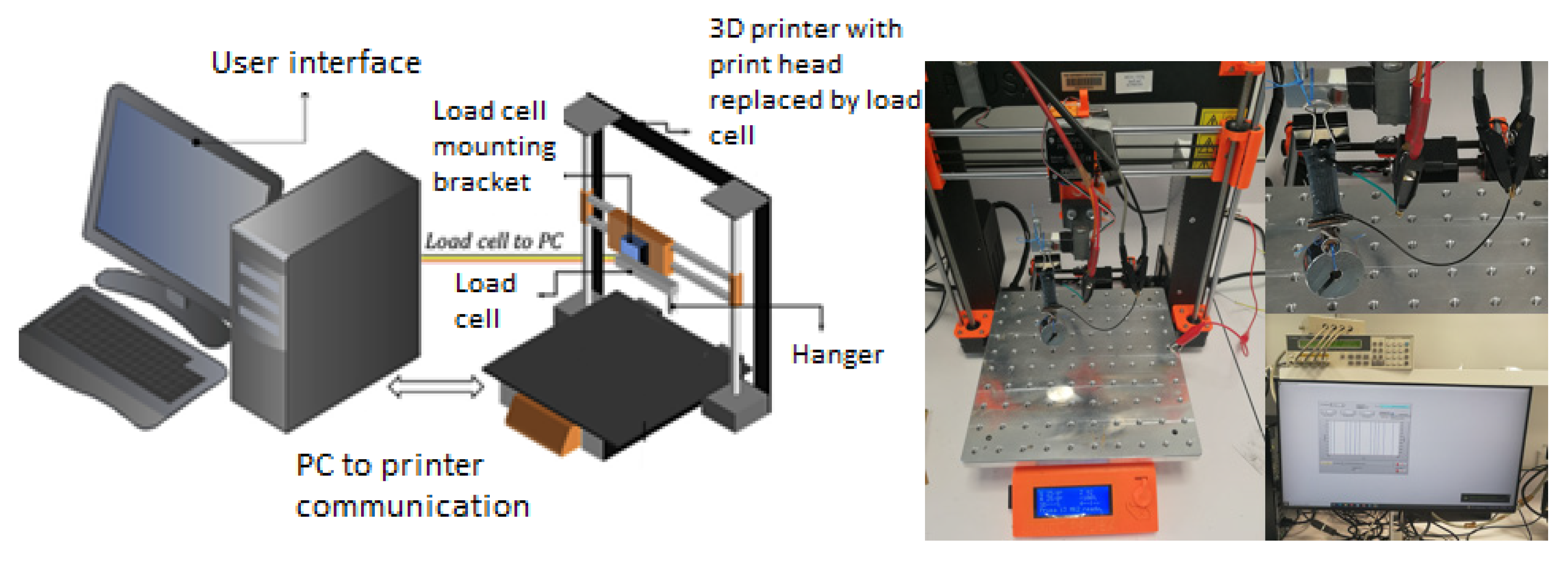
2.4. The Data Collection and Testing Rigs

Figure 5 shows the automated uniaxial stretching rig and testing processes. The set-up collects the capacitance versus strain of the LIDC (Figure 5a) in 1S1L and 2L1S arrangements. The capacitance of the sensor was measured with an Agilent 4263B LCR meter (Figure 5b). A computer was used to control the stretching rig and collect the data from the LCR meter (Figure 5c).
Creep occurs when materials are subjected to a static load over time, such as the joints of the URH potentially being in a specific position and causing the sensor to be statically stretched over a long period. For most stretchable strain sensors, conductive and base materials’ creep affects the sensing performance and long-term stability [36]. Therefore, experiments were conducted to understand the creep behavior of these sensors. Because the creep increases with strain under constant load, a rig capable of keeping constant load was used in this study. Figure 6 shows the rig for measuring the creep of the sensors. This rig uses a modified Prusa i3 printer with a load cell mounted on the printing nozzle holder. A 25 N load cell was attached to measure the loading in the direction of the stretch.

3. Results and Discussion

3.1. Sensor Characteristics

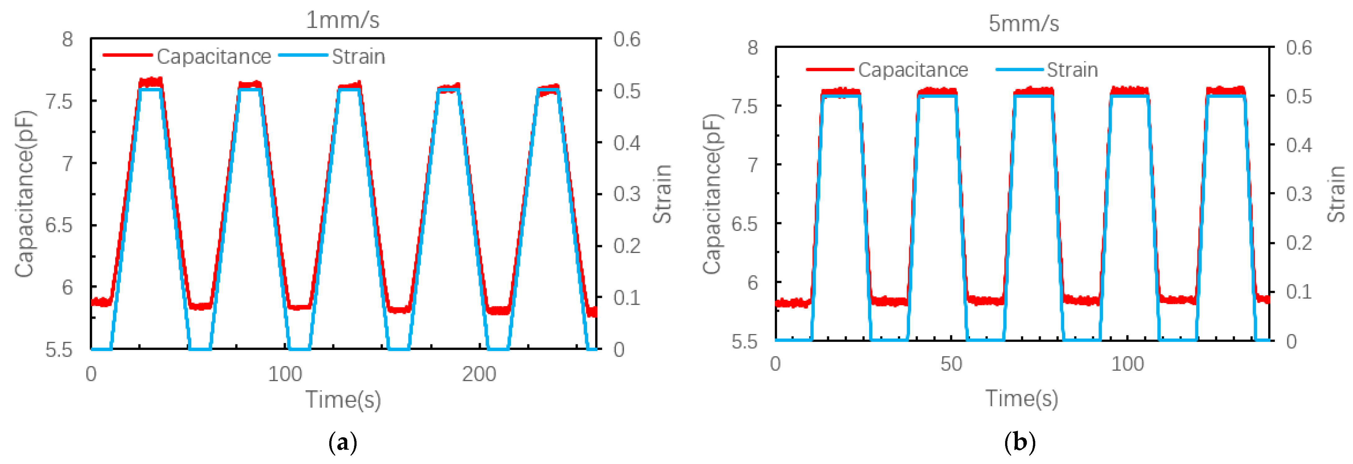
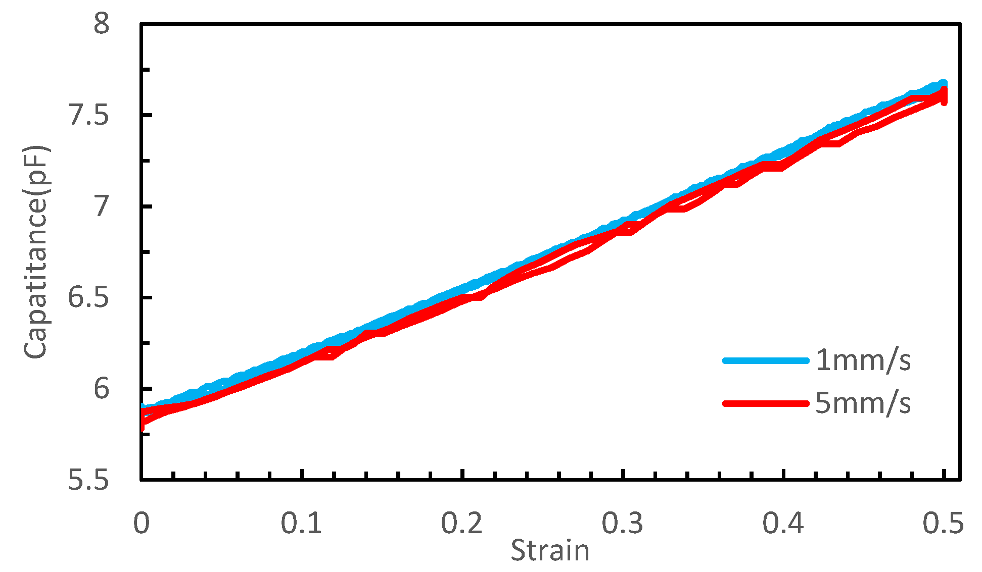
3.1.1. The Characteristics of LIDC Sensor with One-Layer IDC and One-Layer Shield

Figure 7 exhibits the characteristics of the LIDC sensor in the 1L1S arrangement. The results show that the capacitance increases linearly with strain. The capacitance changes by 1.85 pF when the strain is increased from 0% to 50%. Because the sensor is 30 mm long, its sensitivity ( Δ C Δ l ) is 0.1233 pF/mm. The stretching speed at 5mm/s (Figure 7b) sees a nearly similar characteristic to the stretching speed at 1mm/s, which means the sensor can react at a normal grasping speed, considering the reduction ratio, rotation angle, and acceleration of the drive motor.
Figure 8 shows the linearity and hysteresis of this LIDC sensor in a 1L1S arrangement at different stretching speeds. Hysteresis is defined as the difference between two separate measurements taken at the same elongation in a stretching cycle, the first being taken during the stretching process and the other during the retraction process, and then the maximum hysteresis is expressed as
max ε ( 0 ε m a x ) | C p ε C p ε |
where ε is the elongation of the sensor, ε m a x is the maximum elongation, C p ε is the capacitance at the elongation of ε during the stretching process, and C p ε is the capacitance at the elongation of ε during the retracting process.
It shows that the maximum hysteresis is 0.04 pF at 1 mm/s stretching speed and 0.07 pF at 5 mm/s stretching speed. When linearly fitting these two curves, the R-squares are 0.9951 for 1 mm/s and 0.99848 for 5 mm/s, respectively. Hence, the sensor response is independent of the stretch rate, which is in contrast to the piezoresistive sensors made from a mixture of CB and Ecoflex 00-30 [28].

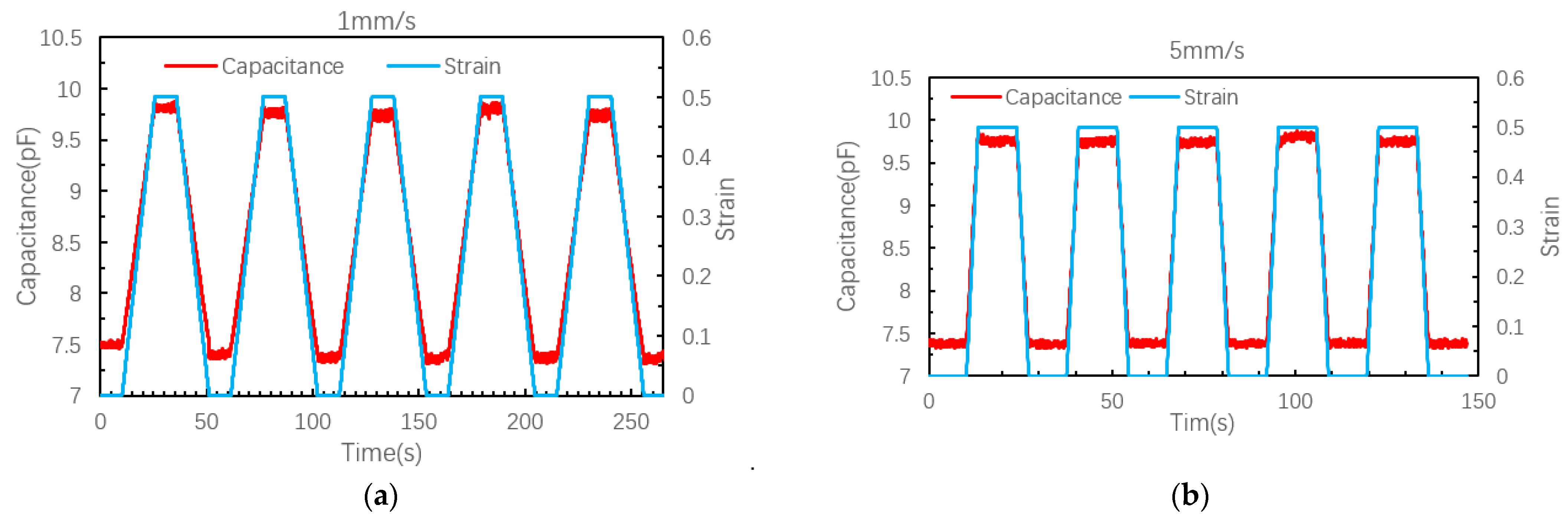
3.1.2. The Characteristics of LIDC Sensor with Two Layers IDC and One-Layer Shield

Figure 9 exhibits the characteristics of the LIDC sensor in the 2L1S arrangement. The response of this configuration is similar to that in Figure 7 but with a higher capacitance value, as the fingers are thicker. Figure 10 exhibits the linearity and hysteresis (~1%) of this LIDC sensor at 30 mm long. It shows that the capacitance changes by 2.25 pF when strained from 0% to 50%, with a sensitivity of about 0.15 pF/mm, slightly higher than that in a 1L1S arrangement. Figure 7 and Figure 9 shows that there are some noises in the capacitance reading, despite having a one-layer shield, and the noise reading is approximately 0.07 to 0.1 pF.
Figure 10 shows the linearity and hysteresis of this LIDC sensor in a 2L1S arrangement at different stretching speeds. It shows that the maximum hysteresis is 0.042 pF at 1 mm/s stretching speed and 0.075 pF at 5 mm/s stretching speed. When linearly fitting these two curves, the R-squares are 0.99994 for 1 mm/s and 0.9995 for 5 mm/s, respectively. Compared with the LIDC sensor in the 1L1S arrangement, the linearity of the LIDC sensor in the 2L1S arrangement is improved slightly because of the increase in its measurement range, but its hysteresis increases, too.

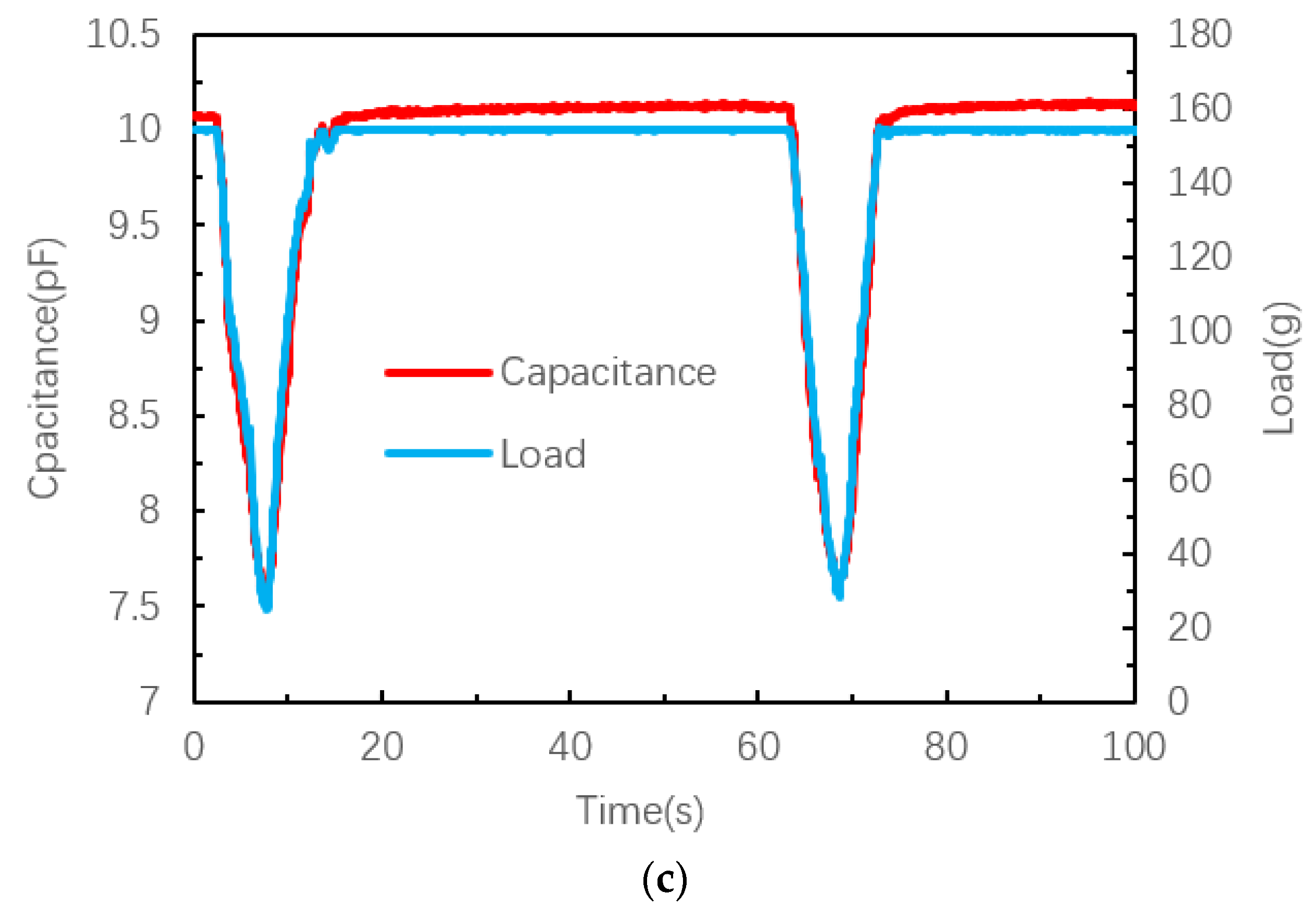
3.1.3. The Creep Behavior of LIDC Sensors with Two Layers of IDC and One Layer Shield

As a more desired sensor, the LIDC sensor in the 2L1S arrangement due to its higher sensitivity was tested further for its creep behavior. Eshwar et al. [24] attempted to use the capacitive sensor in the TIDC configuration and deemed that a detailed study of the creep behavior of the base material (Ecoflex 00-30 with Barium Titanate) is essential to evaluate the stability of the sensor during static loading conditions. He fitted and described the creep behavior of viscoelastic materials using a second-order generalized Kelvin–Voigt (GKV) model.
D ( t ) = D 0 + D 1 ( 1 e t E 1 η 1 ) + D 2 ( 1 e t E 2 η 2 )
where E 1 and E 2 are the retarded elastic moduli, η 1 and η 2 are the vicious dashpot coefficients, and D 0 , D 1   and   D 2 are the respective creep compliances of the KV elements of a second-order GKV model.
As the interest here is the LIDC sensor in the 2L1S arrangement, the creep behavior is studied. Figure 11 shows the creep behavior of the sensor at loads of 60 g, 120 g, and 180 g, respectively. The creeping behavior is aggravated with the increase in the load. The rates of capacitive creep ( Δ C Δ t ) are 0.000667 pF/s and 0.001 pF/s at loads of 120 g and 180 g, respectively. The creep rates are insignificant and suitable for the application in a URH.

3.1.4. The Shielding Configuration Experiment of LIDC Sensors

As explained in the previous sections, shielding the capacitive sensor helps reduce the effect of external interference and noise, especially in a URH where it needs to operate in an unknown environment. Figure 12 displays the change in capacitance versus the distance of a human hand to the LIDC sensor, with (2L1S) and without a shield layer. The test was conducted by placing the sensor on the desk and slowly moving the author’s hand toward the sensor. During this process, the capacitance and distance between the sensor and hand were measured and recorded. This simple experiment shows that shielding offers some protection against parasitic capacitance. The capacitance difference when the author’s hand is 30 mm away from the sensor, and when the hand is touching the sensor, it can be calculated (ΔC). From Figure 12, the LIDC with a one-layer shield, the capacitance changes by 5% ( Δ C C 0 × 100 = { 6.79 6.45 ) 6.79 × 100 ) when the human hand is brought from 30 mm away from the sensor to touching the sensor, compared to ~7.1% ( Δ C C 0 × 100 = { 6.89 6.4 ) 6.89 × 100 )   for the sensor without a shield.

3.2. The Application of the Sensors

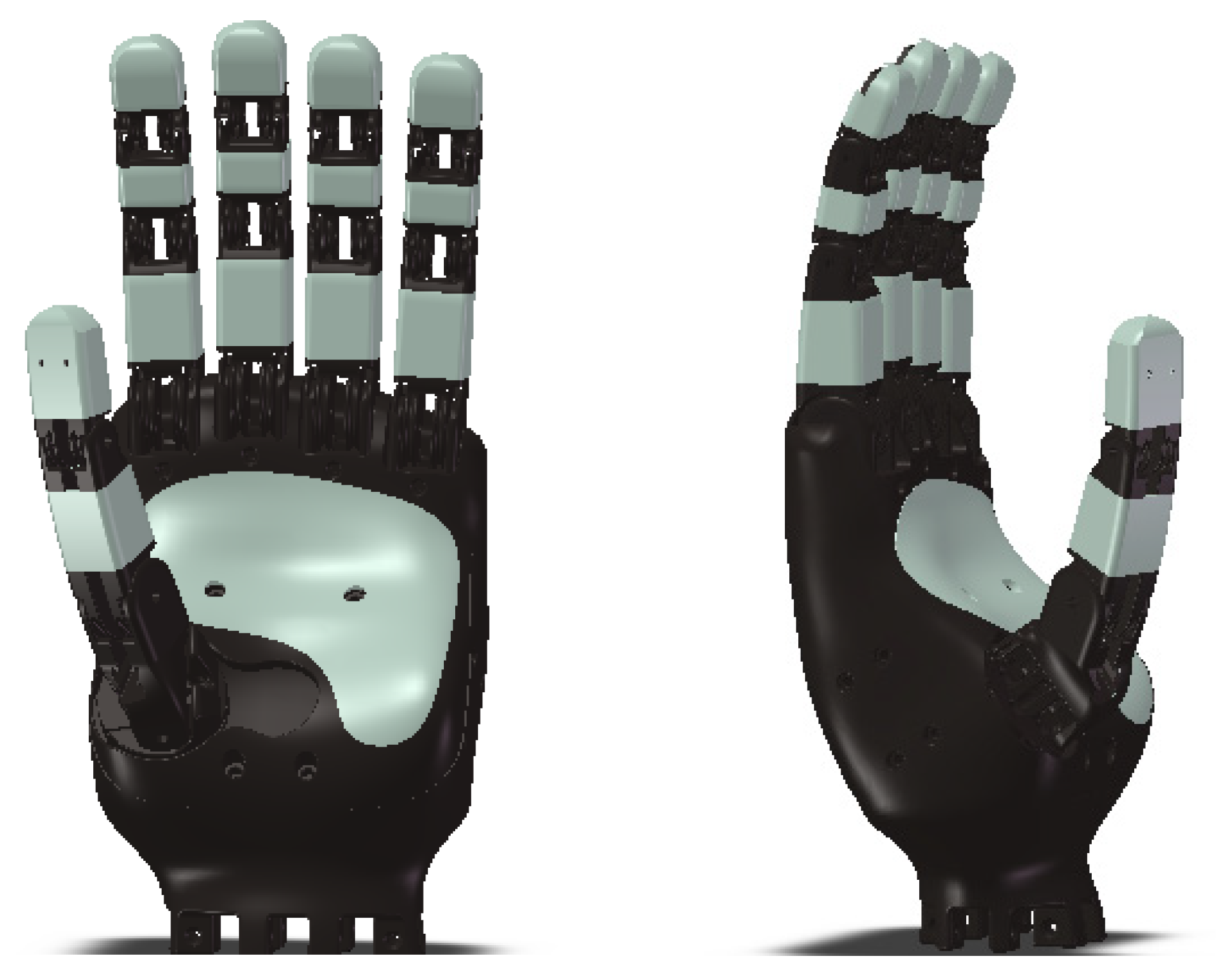
3.2.1. The Underactuated Robotic Hand

A tendon-driven URH (Figure 13) was used. It consists of four fingers, an opposable thumb, and a compliant palm, as homogeneous with a human hand based on the concepts in Refs. [37,38]. All four fingers have a similar structure. Each finger consists of three 3D printed phalanges, pin-jointed together using steel shafts. Additionally, each phalange in the finger has a central channel for tendon routing and a molded finger pad. The tendon-driven actuation mechanism is used to actuate the fingers. A set of passive antagonistic bands molded from polyurethane rubber (PMC 780) were introduced to passively return the finger to its original upright position. The pre-strained bands spanning the phalanges were used to retract all phalanges to their original positions. A complete finger weight is about 35 g. The thumb consists of just the proximal and distal phalanges, consistent with the anatomy of a human thumb.

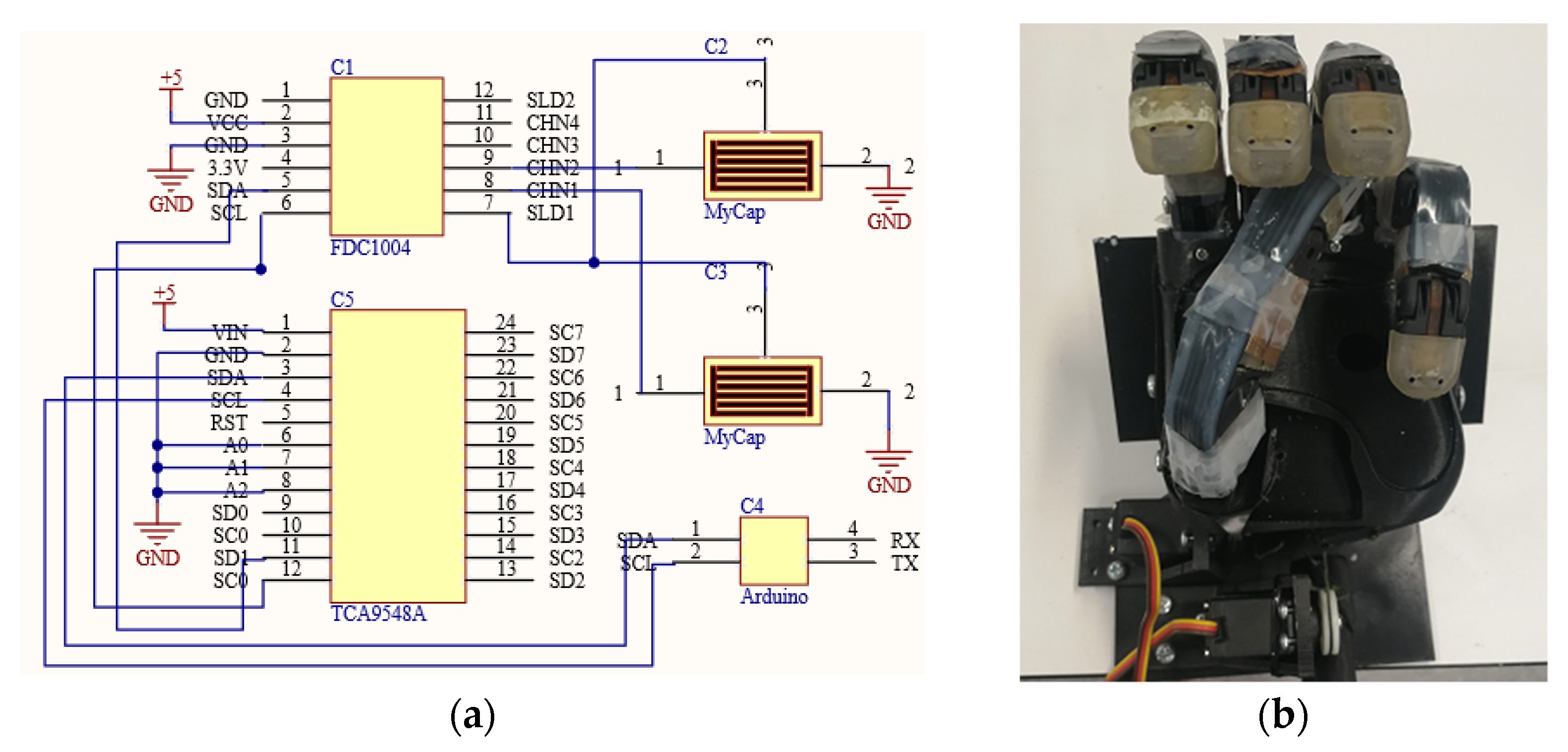
3.2.2. The Measuring Circuits and the Hand with the Sensors

Figure 14a shows the measuring circuits. The FDC1004 (Protocentral Electronics) chip is used to measure the capacitance of the sensors and convert them into their digital equivalent. The chip has four channels, and for the robotic hand, more than four chips are needed. In addition, to know which FDC1004 is read, a 1-to-8 I2C multiplexer TCA9548A (Texas Instruments) is added to the circuits. The capacitance is read by the Arduino and sent to a computer. Figure 14b shows the URH with the two sensors attached to each finger to measure the bending of the proximal interphalangeal (PIP) and metacarpophalangeal (MCP) joints.
Because of a better GF, the LIDC sensors in the 2L1S arrangement were used in the URH. The bending of MCPs and PIPs joints are measured and shown in Figure 15. Because of the variation between each fabricated sensor, the curves in the following plots are different. The gage factor of the sensors when applied to a URH was quantified as pF/° instead of pF/mm.
Table 1 summarizes the performance of the sensors attached to the joints of each finger based on the results presented in Figure 15. The R2 (the coefficient of determination) presents the linearity error, and the sensitivity is defined as the ratio of per unit change in capacitance to the per-unit angular bend of the URH’s fingers. The sensitivity is estimated from the slope of the plots in Figure 15, and the worst-case sensitivity is from the results of the PIP joint of the ring finger, which is 14.571 pF/°.

3.3. Discussion

Stretchable sensors extend the applications of the URHs. Stretchable piezoresistive and capacitive sensors are the two widely used types, with their advantages and disadvantages. The stress relaxation, which is closely related to the materials of piezoresistive sensors, seriously affects the measurement accuracy, contributing to large hysteresis. Further stress relaxation caused the resistance to slowly change over time at static strain, which can cause an error when the URH grips an object and remains static. From the results of this study and also those from previous studies [28], the capacitive sensor does not have the stress–relaxation problem, and its capacitive creep behavior is not obvious and has no effect on the robotic grasping measurement. In terms of measurement, multi-channel capacitance measurement can meet the needs of robotic fingers. The experimental data show that the linearity of the LIDC sensor is favorable for application in finger flexure measurement. The sensor’s worst-case sensitivity is 14.571 fF/° and with the resolution of the FDC1004 chip of 0.5 fF, it is sufficient to resolve the reading from the sensor. The main problem of a capacitance sensor is environmental interference. Adding a shielding layer can reduce the interference but cannot eliminate it. Increasing the initial capacitance by increasing the thickness of the interdigitated fingers, such as that in 2L1S, is another way to reduce the effect of the interference. Filtering and signal processing can further reduce the impact of the interference.
In a previous study [28], a flexible piezoresistive sensor for measuring the joint angle of a manipulator was proposed. Compared to its linearity index (R2 = 0.9923), relative hysteresis (12%), and GF (1.58), this proposed sensor in this article has a linearity index of 0.9995, relative hysteresis of 1% (the ratio of maximum hysteresis to original capacitance), and GF of 2. Therefore, the proposed sensor has a better characteristic.

4. Conclusions

The soft and stretchable capacitive sensor has many applications in robotics. This article presents the fabrication of a soft and stretchable capacitive sensor. Tests show that the sensors have reasonable linearity and tensile properties and can be retrofitted to existing robotic hands. A shield was introduced in the architecture of the sensors to reduce environmental interference. The shield coupling with the sensor helps slightly reduce the effect of parasitic capacitances.
The results show that the TIDC sensor configuration has a higher nonlinearity than the LIDC sensor configuration, and hence, LIDC sensor configuration is more suitable to be applied to a URH, as it simplifies the decoding of the joints’ bending angles. In addition, the TIDC sensor has a nonlinear GF. The LIDC sensor in the 2L1S arrangement is slightly more sensitive. The GF of the LIDC sensor (1L1S) is 0.1233 pF/mm, and the GF of a similar sensor but in a 2L1S arrangement is 0.15 pF/mm; hence, the LIDC sensor in the 2L1S is preferred. Creep response tests show that the LIDC sensor (2L1S) has creep rates of 0.000667 pF/s and 0.001 pF/s at loads of 120 g and 180 g, respectively, which is insignificant when used in a URH when the joints are static when classifying a grasped object.
Although the proposed sensor met the needs of the URH to estimate the size and general shape of the object being grasped, the implementation and testing to validate this will be carried out soon. Moreover, environmental interference remains a major challenge for capacitive sensors. Simply increasing the capacitance and measurement resolution is not a perfect solution, because it does simultaneously increase the impact of environmental disturbances on the sensor. Designing better shielding structures to reduce environmental interference is something that needs further research on sensors.

Author Contributions

Conceptualization, S.Y. and K.A., Methodology, S.Y. and K.A., Experiment Design, S.Y., Data collection, S.Y., Formal analysis, S.Y., Writing, S.Y. and K.A., Resources, K.A., Validation, S.Y., Review & Editing, K.A., Supervision, K.A. All authors have read and agreed to the published version of the manuscript.

Funding

This research received no external funding.

Institutional Review Board Statement

Not applicable.

Informed Consent Statement

Not applicable.

Data Availability Statement

Not applicable.

Acknowledgments

The authors wish to thank Jayden Chapman and Minas Liarokapis for providing the under-actuated robotic hand for this research.

Conflicts of Interest

The authors declare no conflict of interest.

References

  1. Klatzky, R.L.; Lederman, S.J.; Metzger, V.A. Identifying objects by touch: An expert system. Percept. Psychophys. 1985, 37, 299–302. [Google Scholar] [CrossRef] [PubMed] [Green Version]
  2. Vasquez, A.; Kappassov, Z.; Perdereau, V. In-hand Object Shape Identification Using Invariant Proprioceptive Signatures. In Proceedings of the IEEE/RSJ International Conference on Intelligent Robots and Systems, Deajeon, Korea, 9–14 October 2016; pp. 965–970. [Google Scholar] [CrossRef]
  3. Lyubova, N.; Ivaldi, S.; Filliat, D. From passive to interactive object learning and recognition through self-identification on a humanoid robot. Auton. Robot. 2016, 40, 33–57. [Google Scholar] [CrossRef] [Green Version]
  4. Khasnobish, A.; Singh, G.; Jati, A.; Konar, A.; Tibarewala, D.N. Object-shape recognition and 3D reconstructi on from tactile sensor images. Med. Biol. Eng. Comput. 2014, 52, 353–362. [Google Scholar] [CrossRef] [PubMed]
  5. Rebollo, D.R.R.; Pedro, P.; Molina, A. From 3 fingers to 5 fingers dexterous hands. Adv. Robot. 2017, 31, 1051–1070. [Google Scholar] [CrossRef]
  6. Neha, E.; Suhaib, M.; Mukherjee, S.; Shrivastava, Y. Kinematic analysis of four-fingered tendon actuated robotic hand. Aust. J. Mech. Eng. 2021, 3, 1–11. [Google Scholar] [CrossRef]
  7. Kontoudis, G.P.; Liarokapis, M.; Vamvoudakis, K.G.; Furukawa, T. An Adaptive Actuation Mechanism for Anthropomorphic Robotic hands. Front. Robot. AI 2019, 6, 47. [Google Scholar] [CrossRef] [Green Version]
  8. Ryu, W.; Choi, Y.; Choi, Y.J.; Lee, Y.G.; Lee, S. Development of an Anthropomorphic Prosthetic Hand with Underactuated Mechanism. Appl. Sci. 2020, 10, 4384. [Google Scholar] [CrossRef]
  9. Spiers, A.J.; Liarokapis, M.V.; Calli, B.; Dollar, A.M. Single-Grasp Object Classification and Feature Extraction with Simple Robot Hands and Tactile Sensors. IEEE Trans. Haptics 2016, 9, 207–222. [Google Scholar] [CrossRef]
  10. Hao, Z.; Charbel, T.; Gursel, A. A 3D Printed Soft Robotic Hand With Embedded Soft Sensors for Direct Transition Between Hand Gestures and Improved Grasping Quality and Diversity. IEEE Trans. Neural Syst. Rehabil. Eng. 2022, 30, 550–558. [Google Scholar] [CrossRef]
  11. Kappassov, Z.; Corrales, J.A.; Perdereau, V. Tactile sensing in dexterous robot hands- Review. Robot. Auton. Syst. 2015, 74, 195–220. [Google Scholar] [CrossRef] [Green Version]
  12. Hanna, Y.; Mehdi, B.; Kaspar, A. Tactile sensing for dexterous in-hand manipulation in robotics—A review. Sens. Actuators A. Phys. 2011, 167, 171–187. [Google Scholar] [CrossRef]
  13. Luo, S.; Bimbo, J.; Dahiya, R.; Liu, H. Robotic tactile perception of object properties: A review. Mechatronic 2017, 48, 54–67. [Google Scholar] [CrossRef] [Green Version]
  14. Senthil, K.K.; Chen, P.Y.; Ren, H. A review of printable flexible and stretchable tactile sensors. Research 2019, 2019, 3018568. [Google Scholar] [CrossRef] [Green Version]
  15. Obaid, N.; Kortschot, M.T.; Sain, M. Modeling and predicting the stress relaxation of composites with short and randomly oriented fibers. Materials 2017, 10, 1207. [Google Scholar] [CrossRef] [PubMed]
  16. Ding, H.; Chen, J.K. Research on the resistivity attenuation law of cementitious conductive composites induced by stress relaxation. Constr. Build. Mater. 2019, 206, 347. [Google Scholar] [CrossRef]
  17. Reis, P.N.B.; Neto, M.A.; Amaro, A.M. Amaro.Effect of hostile solutions on stress relaxation of carbon/epoxy composites. Polym. Degrad. Stab. 2019, 165, 60–67. [Google Scholar] [CrossRef]
  18. Sousa, A.M.F.; Furtado, C.R.G. Stress relaxation of nitrile rubber composites filled with a hybrid metakaolin/carbon black filler under tensile and compressive forces. Appl. Clay Sci. 2018, 151, 81–188. [Google Scholar] [CrossRef]
  19. Reis, P.N.B.; Silva, M.P.; Santos, P. Stress Relaxation in Delaminated Carbon/Epoxy Composites. Fibers Polym. 2019, 20, 1284–1289. [Google Scholar] [CrossRef]
  20. Chang, X.; Chen, L.; Chen, J.; Zhu, Y.; Guo, Z. Advances in transparent and stretchable strain sensors. Adv. Compos. Hybrid Mater. 2021, 4, 435–450. [Google Scholar] [CrossRef]
  21. Heo, J.S.; Hossain, M.F.; Kim, I. Challenges in Design and Fabrication of Flexible/Stretchable Carbon- and Textile-Based Wearable Sensors for Health Monitoring: A Critical Review. Sensors 2020, 20, 3927. [Google Scholar] [CrossRef]
  22. Kanoun, O.; Bouhamed, A.; Ramalingame, R.; Bautista-Quijano, J.R.; Rajendran, D.; Ammar, A.H. Review on Conductive Polymer/C.N.T.s Nanocomposites Based Flexible and Stretchable Strain and Pressure Sensors. Sensors 2021, 21, 341. [Google Scholar] [CrossRef] [PubMed]
  23. Chen, J.W.; Yu, Q.L.; Cui, X.H.; Dong, M.Y.; Zhang, J.X.; Wang, C.; Fan, J.C.; Zhu, Y.T.; Guo, Z.H. An overview of stretchable strain sensors from conductive polymer nanocomposites. J. Mater. Chem. C Mater. Opt. Electron. Devices 2019, 7, 1171–1173. [Google Scholar] [CrossRef]
  24. Cholleti, E.R.; Stringer, J.; Kelly, P.; Bowen, C.; Aw, K. Studying the creep behaviour of stretchable capacitive sensor with barium titanate silicone elastomer composite. Sens. Actuators A Phys. 2021, 319, 112560. [Google Scholar] [CrossRef]
  25. Devaraj, H.D.; Schober, R.; Picard, M.; Teo, M.Y.; Lo, C.Y.; Gan, W.C.; Aw, K.C. Highly elastic and flexible multi-layered carbon black/elastomer composite-based capacitive sensor arrays for soft robotics. Meas. Sens. 2019, 2, 100004. [Google Scholar] [CrossRef]
  26. Haberman, M.; Cassino, A.; Spinelli, E. Estimation of stray coupling capacitances in biopotential measurements. Med. Biol. Eng. Comput. 2011, 49, 1067–1071. [Google Scholar] [CrossRef]
  27. Wang, D. Capacitive Sensing: Ins and Outs of Active Shielding. Application Report. February 2015. Available online: https://www.ti.com/lit/an/snoa926a/snoa926a.pdf?ts=1645237565469&ref_url=https%253A%252F%252Fwww.google.com.hk%252F (accessed on 1 March 2022).
  28. Devaraj, H.; Giffney, T.; Petit, A.; Assadian, M.; Aw, K. The Development of Highly Flexible Stretch Sensors for a Robotic Hand. Robotics 2018, 7, 54. [Google Scholar] [CrossRef] [Green Version]
  29. Cholleti, E.R.; Stringer, J.; Kelly, P.; Bowen, C.; Aw, K. Mechanical Behaviour of Large Strain Capacitive Sensor with Barium Titanate Ecoflex Composite Used to Detech Human Motion. Robotics 2021, 10, 69. [Google Scholar] [CrossRef]
  30. Zhao, Y.; Liu, Y.; Li, Y.; Hao, Q. Development and Application of Resistance Strain Force Sensors. Sensors 2020, 20, 582. [Google Scholar] [CrossRef]
  31. Li, J.; Fang, L.C.; Sun, B.; Li, X.X.; Kang, S.H.K. Review-Recent Progress in Flexible and Stretchable Piezoresistive Sensors and Their Applications. J. Electrochem. Soc. 2020, 167, 37561. [Google Scholar] [CrossRef]
  32. Wang, W.; Yang, S.; Ding, K.; Jiao, L.; Yan, J.; Zhao, W.; Ma, Y.Y.; Wang, T.Y.; Cheng, B.; Ni, Y.H. Biomaterials- and biostructures Inspired high-performance flexible, stretchable strain sensors: A review. Chem. Eng. J. 2021, 425, 129949. [Google Scholar] [CrossRef]
  33. Yan, T.; Wang, Z.; Pan, Z.J. Flexible strain sensors fabricated using carbon-based nanomaterials: A review. Curr. Opin. Solid State Mater. Sci. 2018, 22, 213–228. [Google Scholar] [CrossRef]
  34. Amjadi, M.; Yoon, Y.J.; Park, I. Ultra-stretchable and skin-mountable strain sensors using carbon nanotubes-Ecoflex nanocomposites. Nanotechnology 2015, 26, 37550. [Google Scholar] [CrossRef] [PubMed]
  35. Liu, Y.; Wang, H.; Zhao, W.; Zhang, M.; Qin, H.; Xie, Y. Flexible, Stretchable Sensors for Wearable Health Monitoring: Sensing Mechanisms, Materials, Fabrication Strategies and Features. Sensors 2018, 18, 645. [Google Scholar] [CrossRef] [PubMed] [Green Version]
  36. Kidner, N.J.; Homrighaus, Z.J.; Mason, T.O.; Garboczi, E.J. Modeling interdigital electrode structures for the dielectric characterization of electroceramic thin films. Thin Solid Films 2006, 496, 539–545. [Google Scholar] [CrossRef]
  37. Gao, G.; Shahmohammadi, M.; Gerez, L.; Kontoudis, G.; Liarokapis, M. On Differential Mechanisms for Underactuated, Lightweight, Adaptive Prosthetic Hands. Front. Neurorobot. 2021, 15, 702031. [Google Scholar] [CrossRef] [PubMed]
  38. Gao, G.; Chapman, J.; Matsunaga, S.; Maruyama, T. A Dexterous, Reconfigurable, Adaptive Robot Hand Combining Anthropomorphic and Interdigitated Configurations. In Proceedings of the IEEE/RSJ International Conference on Intelligent Robots and Systems, Prague, Czech Republic, 27–31 September 2021; pp. 7209–7215. [Google Scholar] [CrossRef]
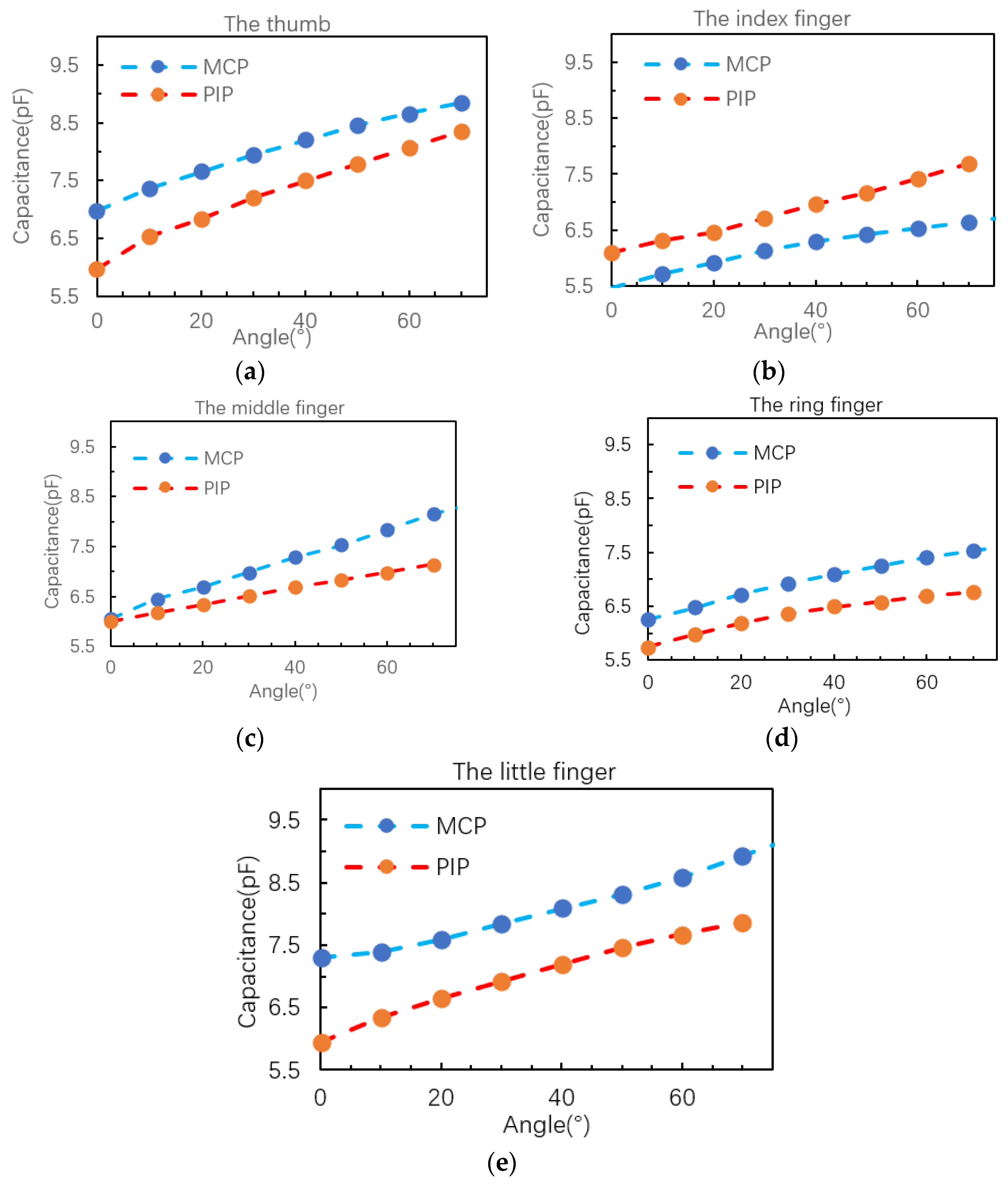
Figure 1. The (a) sensor in LIDC configuration, (b) sensor in TIDC configuration.
Robotics 11 00058 g001
Figure 2. Simulation results of the capacitance and GF versus the length of the sensor. (a) LIDC sensor, and (b) TIDC sensor. The unstretched dimensions are l = 30   mm , ω = 1   mm , and α = 1   mm .
Robotics 11 00058 g002
Figure 3. Schematic representation of the architecture process of the sensor. (a) One-layer IDC with one-layer shield (1L1S), (b) two-layer IDC with one-layer shield (2L1S), (c) two-layer IDC with two-layer shield (2L2S).
Robotics 11 00058 g003
Figure 4. Schematic representation detailing the fabrication steps involved in making the Ecoflex coated C.B./Ecoflex electrodes. (a) The Ecoflex 00-30 substrate, (b) Ecoflex 00-30/CB layer is added to the substrate as a shield, (c) another layer of Ecoflex 00-30 is added, (d) a stencil with the LIDC pattern is placed on top of the cured Ecoflex 00-30, (e) the Ecoflex 00-30/CB is doctor-bladed to create the LIDC structure, and (f) a protective Ecoflex 00-30 is added to protect the LIDC structure.
Robotics 11 00058 g004
Figure 5. The rig for measuring the capacitance versus strain. (a) Stretching the LIDC sensor, (b) Agilent 4263B LCR is used to measure the capacitance as the sensor is being stretched, and (c) the computer controls the stretching rig and collects the data.
Robotics 11 00058 g005
Figure 6. The rig for testing the creep behavior of the sensor.
Robotics 11 00058 g006
Figure 7. The capacitance response of an LIDC sensor in the 1S1L arrangement. Stretch rate of (a) 1 mm/s and (b) 5 mm/s.
Robotics 11 00058 g007
Figure 8. The hysteresis of the LIDC sensor (1L1S) at the stretching speeds of 1 mm/s and 5 mm/s.
Robotics 11 00058 g008
Figure 9. The capacitance response of an LIDC sensor in a 2L1S arrangement. Stretch rate of (a) 1 mm/s and (b) 5 mm/s.
Robotics 11 00058 g009
Figure 10. The hysteresis of the LIDC sensor (2L1S) at the stretching speeds of 1 mm/s and 5 mm/s.
Robotics 11 00058 g010
Figure 11. The creep behavior of the sensor at different loads: (a) 60 g, (b) 120 g, and (c) 180 g.
Robotics 11 00058 g011aRobotics 11 00058 g011b
Figure 12. Experimental results show the effect of parasitic capacitance introduced by a human hand in proximity to the sensor.
Robotics 11 00058 g012
Figure 13. The under-actuated robotic hand.
Robotics 11 00058 g013
Figure 14. (a) The interfacing electronics with LIDC in a two-layered IDC and one-layered shielded configuration with Arduino, and (b) the URH with sensors attached.
Robotics 11 00058 g014
Figure 15. The experimental results of sensors attached to the fingers of a URH show the relationship between the capacitances and bending angles of the MCP and PIP joints for the (a) thumb, (b) index finger, (c) middle finger, (d) ring finger, (e) little finger.
Robotics 11 00058 g015
Table 1. The performance of the sensors attached to the URH.
Finger NameJoint NameCapacitance Range (pF)Sensitivity (pF/°)R2
The thumbMCP1.870.0267140.9885
PIP2.380.0340.9884
The index fingerMCP1.290.0184290.9753
PIP1.60.0228570.9962
The middle FingerMCP2.380.029750.9981
PIP1.140.0162860.9993
The ring fingerMCP1.390.0173750.9851
PIP1.020.0145710.9658
The little fingerMCP1.970.0246250.9838
PIP1.920.0274290.9896
Publisher’s Note: MDPI stays neutral with regard to jurisdictional claims in published maps and institutional affiliations.

