Article

A New Hyperloop Transportation System: Design and Practical Integration

Power Electronics and Drives Applications Lab (PEDAL), Ontario Tech University, Oshawa, ONT L1G 0C5, Canada
*
Author to whom correspondence should be addressed.
Robotics 2022, 11(1), 23; https://doi.org/10.3390/robotics11010023
Submission received: 14 December 2021 / Revised: 22 January 2022 / Accepted: 29 January 2022 / Published: 8 February 2022
(This article belongs to the Special Issue Advances in Industrial Robotics and Intelligent Systems)

Abstract

:
This paper introduces a new Hyperloop transportation system’s design and implementation. The main contribution of this paper is the design and integration of propulsion components for a linear motion system, with battery storage. The proposed Hyperloop design provides a high-speed transportation means for passengers and freights by utilizing linear synchronous motors. In this study, a three-phase inverter was designed and simulated using PSIM. A prototype of this design was built and integrated with a linear synchronous motor. The operation of full system integration satisfies a proof-of-concept design. A study of the inverter system in conjunction with a linear synchronous motor for a ridged Hyperloop system is made. The prototype of this system achieves propulsion for the bidirectional movements. Battery state of charge simulation results are given in a typical motoring and braking scenario.

1. Introduction

Today, transportation is a major tool for a growing economy, ranging from daily commutes to large scale freight transportation. However, with the ever-growing increase in population and thus the demand for high-speed transportation raises issues regarding air pollution and climate change. According to data for global emissions in 2020, it was found that 24% of the global greenhouse gas emission is due to fuel dependent transportation [1]. Energy security and climate change are major challenges that need to be addressed for the future generation. In 2016, the Paris Agreement was officially instated for the parties in the agreement to address the climate change problem. This agreement is only a stepping stone to combat this issue. This paper studies the design of a conceptual, novel, and electric mode of transportation known as the Hyperloop. Companies such as Virgin Hyperloop One, Transpod Hyperloop, and HyperloopTT are investing in the research and development of the proposed Hyperloop technology. The Hyperloop system offers a promising alternative to conventional train transportation, presenting a safer, faster, more reliable, and environmentally friendly method of transportation in contrast to conventional transportation. Hyperloop transport is a method of passenger and freight transport that uses vactrain design, incorporating low pressure and air resistance within a tube. Various studies such as [2,3] propose the concepts of utilizing linear motors to facilitate the propulsion and levitation force. The study in [3] presents a Hyperloop system based on electromagnetic propulsion of vehicles (similar technology in magnetic levitated trains) in vacuum tubes to reduce air pressure. Levitation is achieved by generating a repulsive force from the tube levitation system onto the vehicle. Additionally, propulsion is achieved through a traction force generated by moving magnetic field created by linear multi-pole motors [3]. The propulsion force is generated through a spatially moving magnetic field. This is achieved by a three-phase inverter powering and controlling the linear motor [3]. The levitation of a Hyperloop can be achieved either by electromagnetic suspension (EMS) or electrodynamic suspension (EDS) [4]. Due to the complexity of EMS [5], the design discussed in this paper utilizes the concepts of EDS [6]. However, in practicality there are many other factors, such as cost, that come into play. Thus, the use of EDS may not be recommended for a full-scale system. There are two types of linear motors that are commonly studied regarding magnetic levitation trains: the linear induction motor (LIM), such as the one employed in [3], and the linear synchronous motor (LSM). Historically, the LIM is a popular choice for magnetic levitation train. It has attractive features such as cost and low complexity. However, LSM has a high-power factor and provides higher efficiency [7,8,9]. The magnetic levitation system uses sets of superconducting magnets to create repulsion and attractive forces allowing for levitation and propulsion in conjunction with a linear synchronous motor [10]. The pod (vehicle) in this system travels along a guideway of magnets. Stability and speed control is facilitated by sophisticated control algorithms such as field-oriented control [5,10,11,12]. The foundation of this system is the use of electromagnetism concepts as applied to thrust generation. The magnetic fields are produced by permanent and superconducting magnets and electromagnets in a static or dynamic mode. Superconducting electromagnets require an electric current that is significantly less than conventional electromagnets [13]. The repulsive and attraction forces allow for levitation and propulsion without contact. A higher lift force to magnetic ratio is ideal for efficient energy consumption. Forces created depend on the placement of polarities of the magnets. Lastly, the control system for the LSM drive follows the field-oriented control approach. This popular control approach has been studied in various papers such as [5,14]. The study in [14] develops electromagnetic thrust and levitation force via field-oriented control. Various other papers, such as the one reported in [15], study the control of AC motors using the d-q axes model. The dynamic model of a permanent magnet linear synchronous motor (PMLSM) is reported in [16]. Hyperloop topics have been reported in some literature works such as [17,18]. The work in [17] reports the achievability of a Hyperloop system. They present the technical issues in building such an infrastructure. They estimate that a Hyperloop pod traveling at 1200 km/h for an estimated weight of 26,000 kg would require 689 kW of power. Additionally, they calculated that the cost for building the Hyperloop infrastructure in Poland of 3000–30,000 km long tracks would cost over $50 billion. In [18], the authors discuss the electric power requirements for a full-scale Hyperloop. Currently, there is limited research on the topic of integration of Hyperloop propulsion and levitation system via linear synchronous motors. This paper is uniquely structured to give the design of the inverter, linear motor, and overall integration of the system.

2. LSM Model and Controller Design

2.1. Modeling of the Linear Synchronous Motor

The core structure of the prototype is the linear synchronous motor (LSM) which makes up the pod and the track. A diagram for an LSM is shown in Figure 1, which is an unrolled form of a traditional rotary motor which consists of a stator and a rotor. The symbol ‘τ’ represents the pole pitch. It is important to understand the rotary synchronous machine and its properties to correctly form mathematical equations describing the motor characteristics. In terms of rotary machines, characteristics such as torque, angular velocity, and number of pole pairs can be defined. The linear machine can be defined with similar characteristics; however, in respect to the linear machine, the terms are defined as thrust, linear speed, and pole pitch. The stator is powered with three-phase AC current to produce alternating magnetic fields. The rotor is a line of permanent magnets [19]. The referred study uses an LSM that has an ironless core motor ideal for linear motion. The rotor is the moving part (also known as the mover or the pod) lined with permanent magnets and the stator is fixed on the track made up of coils (between the slots shown in Figure 1) receiving the three-phase AC currents [20]. When the stator produces magnetic fields, there are alternating attraction and repulsion forces created between the track and the pod. This allows the pod to propel back and forth on the track without any additional assistance. To model the linear synchronous motor, the mathematical model studied in [5,10,11,12,21] was incorporated. For generic analysis, permanent magnet synchronous motor equations were used as an equivalent to the linear synchronous motor. Additionally, this was done because PSIM does not have a linear synchronous motor model and remodeling an LSM was out of scope of this research. However, it is important to note the differences between the linear synchronous motor and its rotary counterpart. The linear motor has different mechanical properties such as thrust force and linear velocity as opposed to torque and angular velocity. In terms of performance, linear motor has non idealities such as the end effect. This is caused by the unrolled, opened structure of the motor. The end effect in linear motors influences the propulsion force and motor efficiency [22,23,24]. However, the end effect was neglected in this study. The justification for this is because the influence of end effect is not as significant for long primary linear motors moving at high speed [24]. This further simplifies the linear synchronous motor model. The permanent magnet linear synchronous motor (PMSM) voltage equation in ‘abc’ form is given in (1).
[ u a b c ] = [ R a b c ] [ i a b c ] + d [ L a b c ] d θ r ω r [ i a b c ] + [ L a b c ] d [ i a b c ] d t + d [ ψ M a b c ] d θ r ω r
where Labc is the stator a, b, and c phase self-mutual inductance matrix. This is shown in (2).
L a b c = [ L a a ( θ r ) M a b ( θ r ) M a c ( θ r ) M b a ( θ r ) L b b ( θ r ) M b c ( θ r ) M c a ( θ r ) M c b ( θ r ) L c c ( θ r ) ]
Additionally, ΨMabc is the stator a, b, and c phase flux linkages due to the permanent magnets and damper windings on the rotor. This is shown in (3).
Ψ M a b c = [ Ψ M a ( θ r ) Ψ M a b ( θ r 2 π ) Ψ M c ( θ r + 2 π 3 ) ]
As seen in (1), the voltage is dependent on the phase self-inductance, which respects the rotor position of the PMSM. The solution of the system can be simplified by using the reference frame theory. This is achieved by taking one set of variables and transforming it to another [11]. To transform the a, b, and c stator variables into rotor dqo axis, the transformation in (4) is used.
T q d o R = 2 3 ( c o s ( θ r ) c o s ( θ r 2 π 3 ) c o s ( θ r + 2 π 3 ) s i n ( θ r ) s i n ( θ r 2 π 3 ) s i n ( θ r + 2 π 3 ) 1 2 1 2 1 2 )
The new, transformed dqo voltages are given in (5)–(7).
u s q = R s i s q + d Ψ s q d t + ω r Ψ s d
u s d = R s i s d + d Ψ s q d t ω r Ψ s d
u s o = R s i s o + d Ψ s o d t
Using the equivalent circuits, the electromagnetic torque can be derived. However, to simplify the equation, some assumptions can be made. For surface mounted rotors, the reluctance torque of the motor is zero. This is because the stator q and d axis inductances are equal. Assuming the PMSM does not have any damper windings and only built of surface mounted magnets, then only the excitation torque will be present [11]. Thus, the final derived equation for the electromagnetic torque is given in (8). As it can be seen, the electromagnetic torque is dependent on the q – axis component of the stator current.
T e = 3 2 p {   ψ s d i s q }

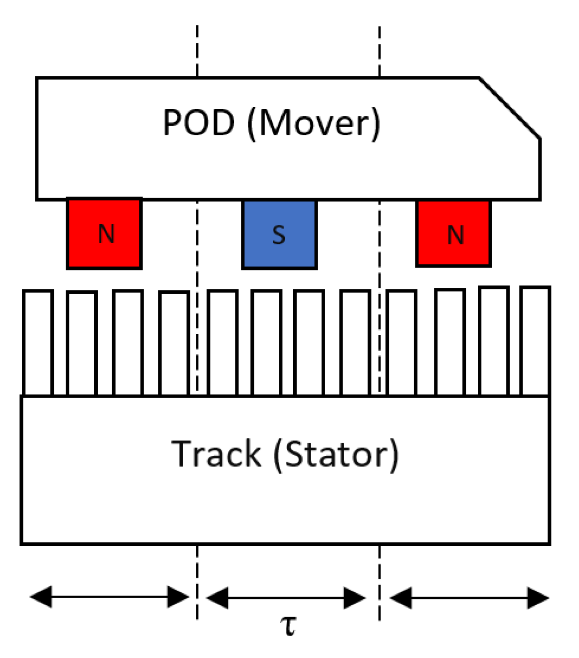
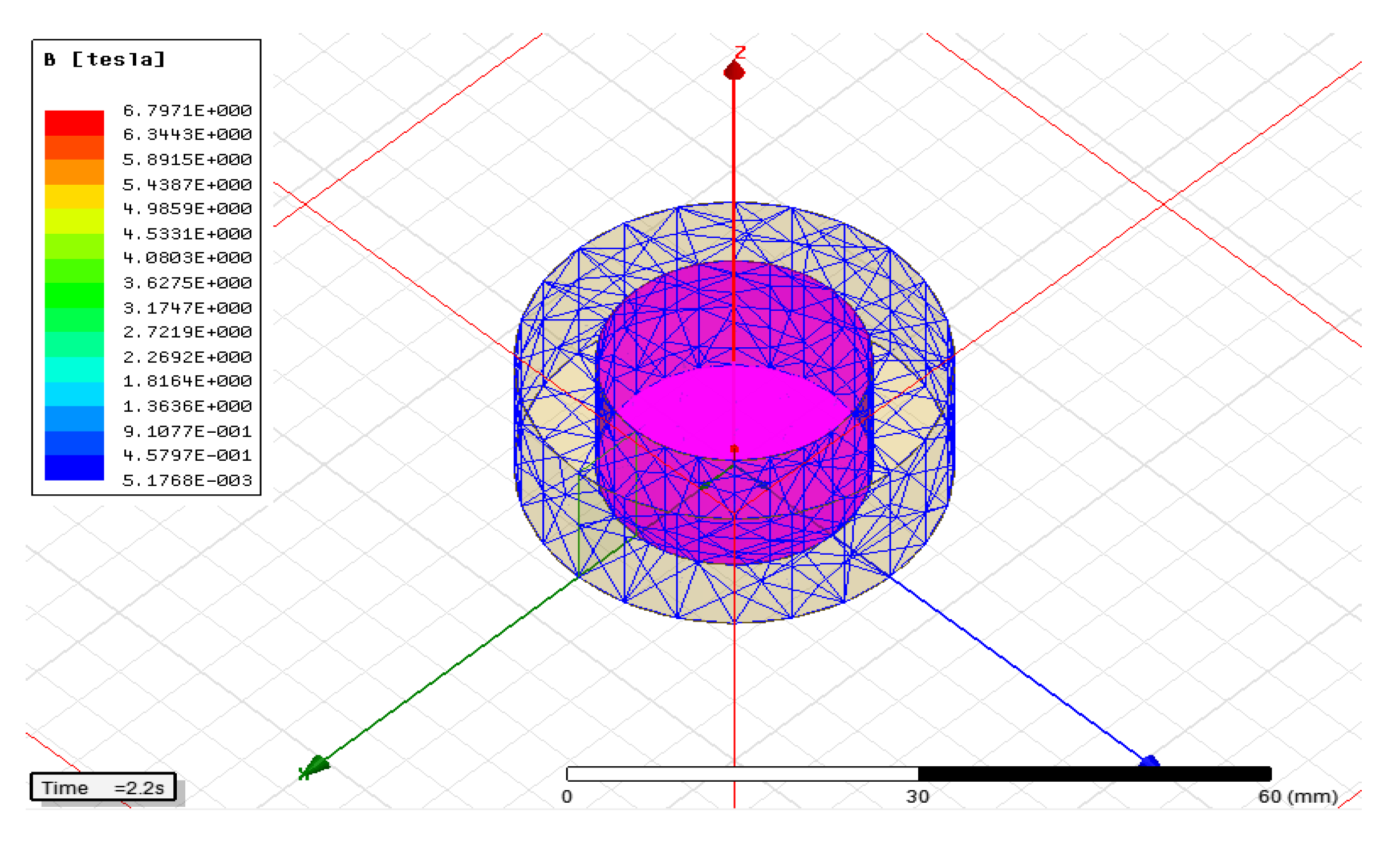
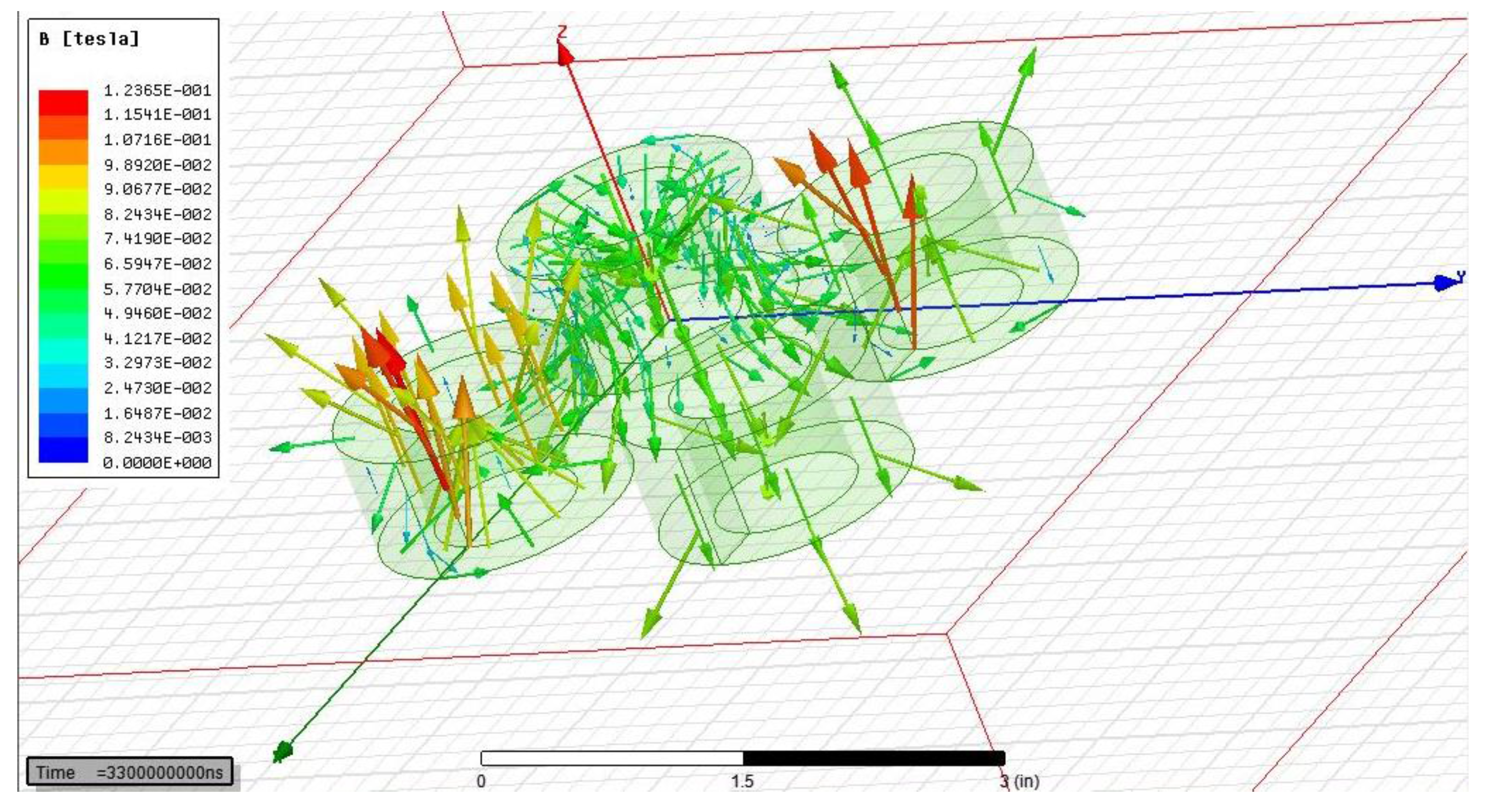
2.2. Permanent Magnet Configuration

For the pod, one important consideration is the permanent magnets’ arrangement. This paper studies the use of the Halbach arrangement. The Halbach Array is an arrangement of permanent magnets in such a way that the magnetic field is stronger on one side than the other. This phenomenon can be realized by rotating each magnet 90 degrees from the previous orientation so that the polarities of the magnets do not repeat. This causes each magnet to strengthen the magnetic field on one side while a single magnet or multiple magnets facing the same orientation would have uniform magnetic field strength around the cluster of magnets. Employing the Halbach Array theory, the magnetic force of a linear motor can be increased without increasing the size of the permanent magnets. The Halbach Array is optimal for linear motors as only one side of the stator is used for levitation and linear motion. The prototype was built in a way that the permanent magnets are placed near the top and underside of the primary element (rotor) using a ‘C”-shaped frame. The magnetic fields of the top and bottom magnet sets were aimed towards each other so that the rotor could achieve higher speed, acceleration, travel accuracy, positioning accuracy, and cycle times through combined attractive and repulsive forces.

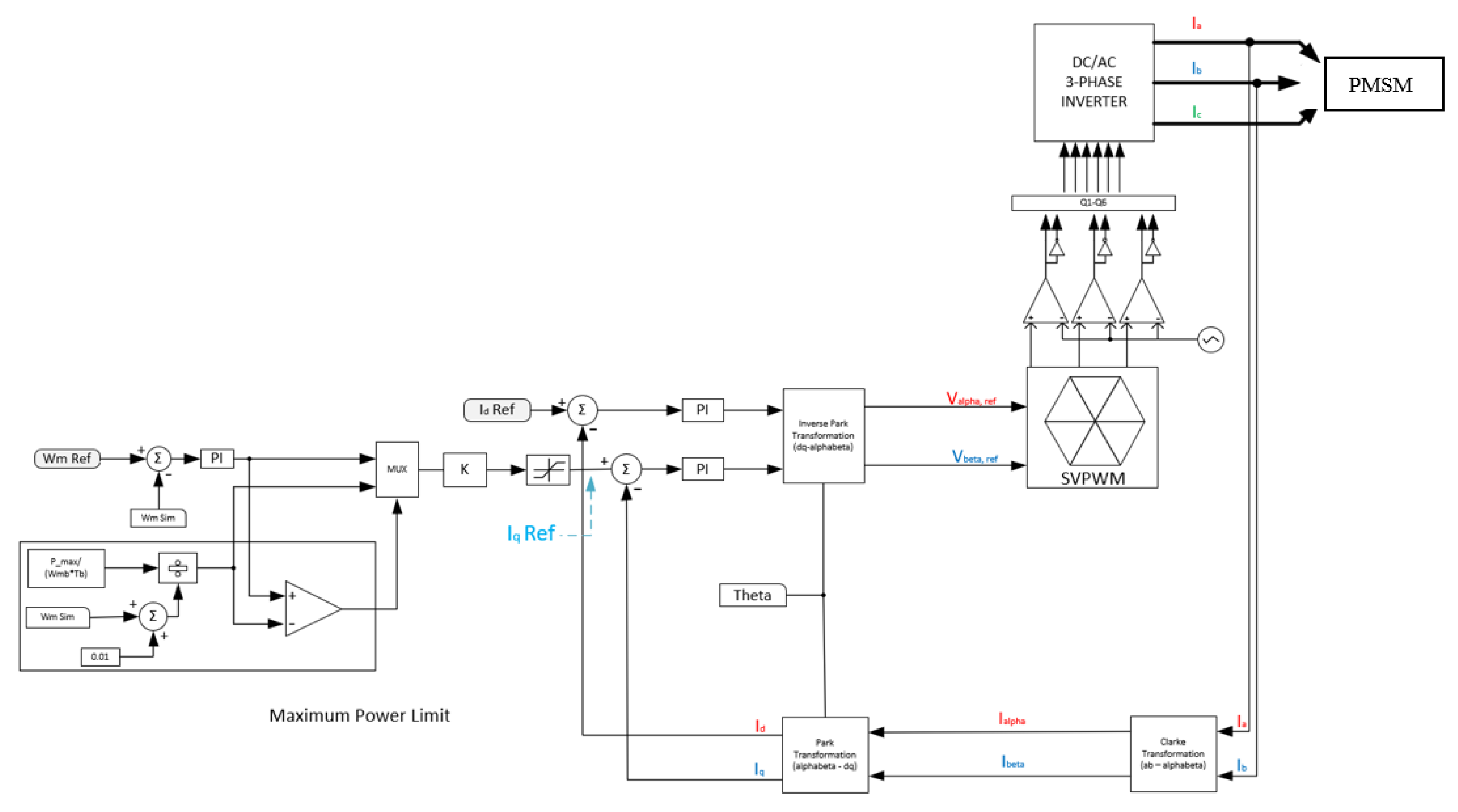
2.3. Field Oriented Control

The design of FOC is based on the mathematical model of PMSM mentioned previously. The controller design topology is a closed loop system that includes proportional integral (PI) regulators. More specifically, it includes a speed regulator and two current controllers [5,11]. The block diagram for the control scheme is seen in Figure 2. The block diagram also gives a general overview of the circuit design. The PMSM is controlled and powered via the three-phase inverter. The inverter’s source voltage is an external dc voltage source, either from a battery or from the utility rectified to a dc source. At the output of the load there is a speed sensor. The remaining blocks are part of the controller. The process of FOC is straightforward. As it is a closed loop design, it relies on various sensor data to appropriately reach steady state. The steps are as follows. First, set a reference or desired motor speed. Next, obtain three-phase current (ia, ib, and ic) readings to convert it to qd0 form. Additionally, for the transformation, the rotor position of the PMSM is required. This can be obtained by first reading the speed sensor value to obtain the angular velocity.
Next integrate the velocity to get position (rotor position θr). These four inputs provide the quadrature, direct, and zero currents (iq, id, i0). These are the measured values. The reference Id current is set to zero. This allows the control of q-axis current (torque). The reference iq is obtained by first calculating the error signal of the speed (measure the difference) then place the error signal into a PI regulator (speed regulator). For the FOC of the PMSM design, the output of the regulator is the iq reference. The error signal of the reference iq and the measured iq is calculated. This is then placed into another regulator (current regulator). A similar process for the Id loop is done. Finally, the resultant signals are placed into an inverse transformation block (dq0 to abc). These signals are now the reference voltage for the PWM signals controlling the switching sequence of the inverter. Additionally, space vector pulse width modulation (SVPWM) technique was implemented for this study. It works by obtaining an optimal switching sequence for the inverter switches. This can be obtained by taking the signals into the alpha beta frame of reference [26]. The inverter output voltages are shown in (9).
[ V a V b V c ] = V d c 3 ( 2 1 1 1 2 1 1 1 2 ) [ C 1 C 2 C 3 ]
V s = V α + j V β = 2 3   ( V a + V b e j 2 π 3 + V c e j 4 π 3 )
The final signals after the PI regulator go into the SVPWM block. This facilitates an optimal switching sequence for the PMSM control. The parameters of the regulator are calculated by using smart control in PSIM and analyzing the system performance.

2.4. LSM Formulas to Generate Specifications

The power can be expressed in terms of the thrust force and the synchronous speed given in Equation (11). The velocity for a linear synchronous motor is given by the frequency and pole pitch of the motor. The thrust can be calculated by determining the mass and acceleration of the linear motor.
P t h r u s t = F x , t h r u s t · v s = m a · 2 f τ
Additionally, the thrust density (N/m2) is described by Equation (12). Where ‘p’ is the pole pairs, and Li is the armature stack length.
f x , t h r u s t = F x , t h r u s t 2 p τ L i = m a · 2 f τ
The efficiency and the power factor of the system are given respectively by the following Equations (13) and (14).
η = F x v s F x v s + 3 I 2 R
P F = F x v s + 3 I 2 R 3 V I
The motor parameters used for simulation are provided in Table 1.

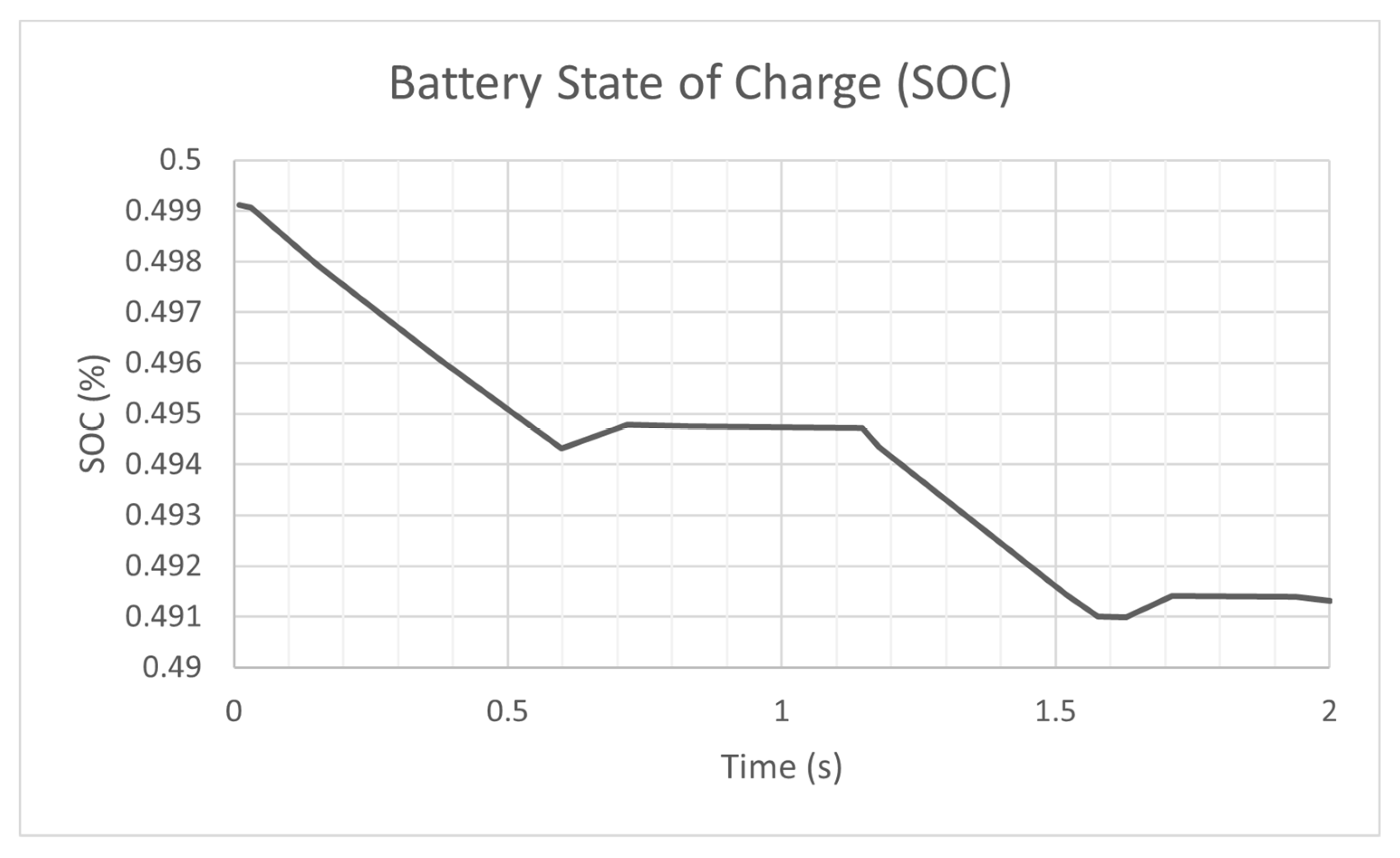
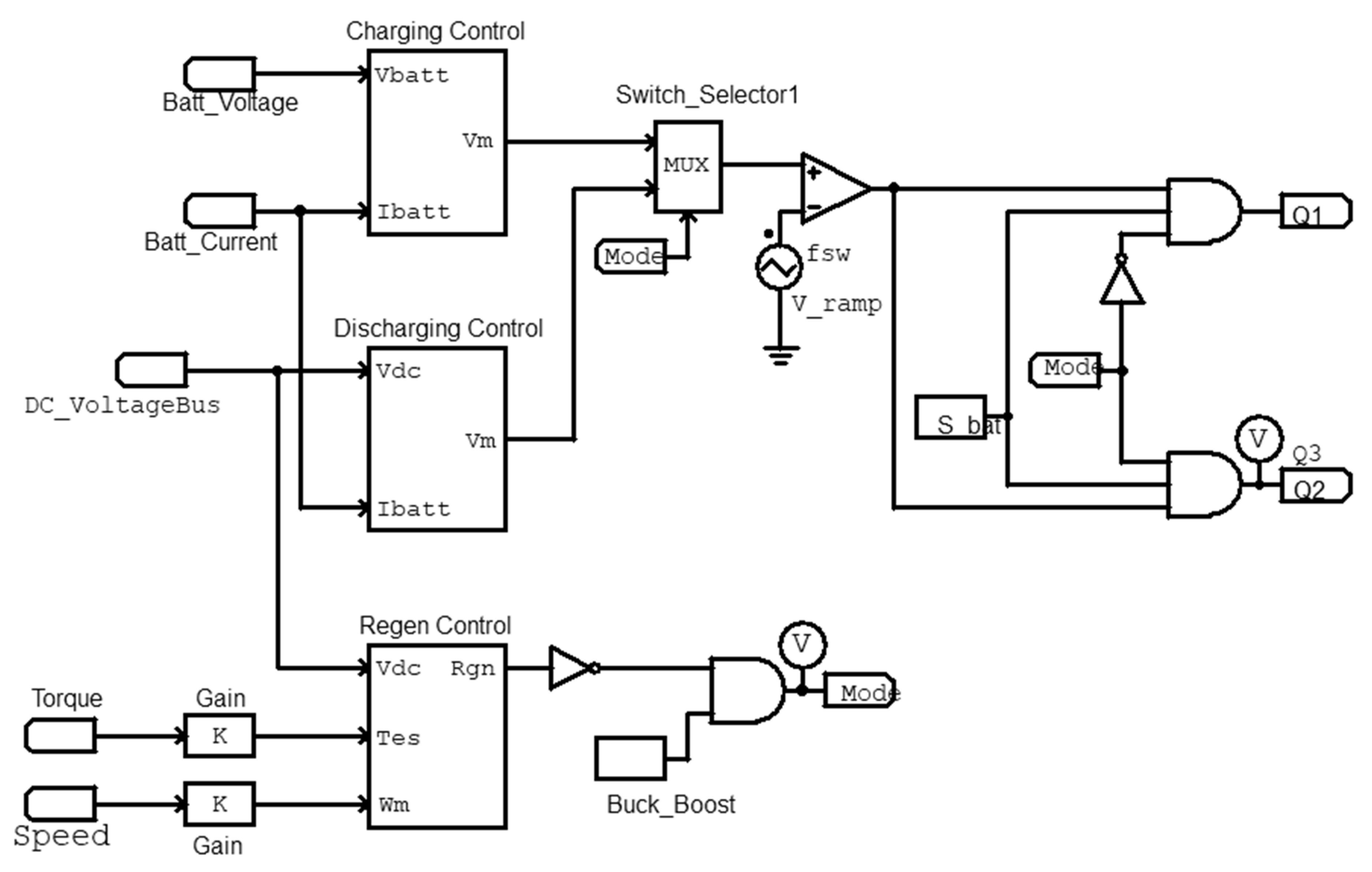
2.5. Modeling of Battery and Bidirectional Converter

The DC voltage source is provided by a lithium-ion battery. Accumulative Parameter values can be calculated using (15)–(17). The parameters for a singular battery are given in Table 2. The rated value can be looked up from the manufacture data sheets. Ks and Kp are voltage and capacity derating factors which are set to 1.
E r a t e d _ t o t a l = N S · K S · E r a t e d
Q r a t e d _ t o t a l = N p · K p · Q r a t e d
R b a t t e r y _ t o t a l = N s N p · R b a t t e r y
The parameters for the battery were calculated based on a prototype design for a 130-kW inverter system, with 750 VDC to power the linear motor. A typical bidirectional DC/DC converter is implemented to observe the generating and motoring modes and its effect on the modeled battery. The converter operates in the boost mode when the PMSM is in the motoring mode of operation (i.e., battery discharging). In regenerative mode of operation, the converter is the buck mode (i.e., battery charging). The block diagram for the control setup is given in Figure 3. The output to this controller determines the mode of operation of the buck-boost DC-DC converter.

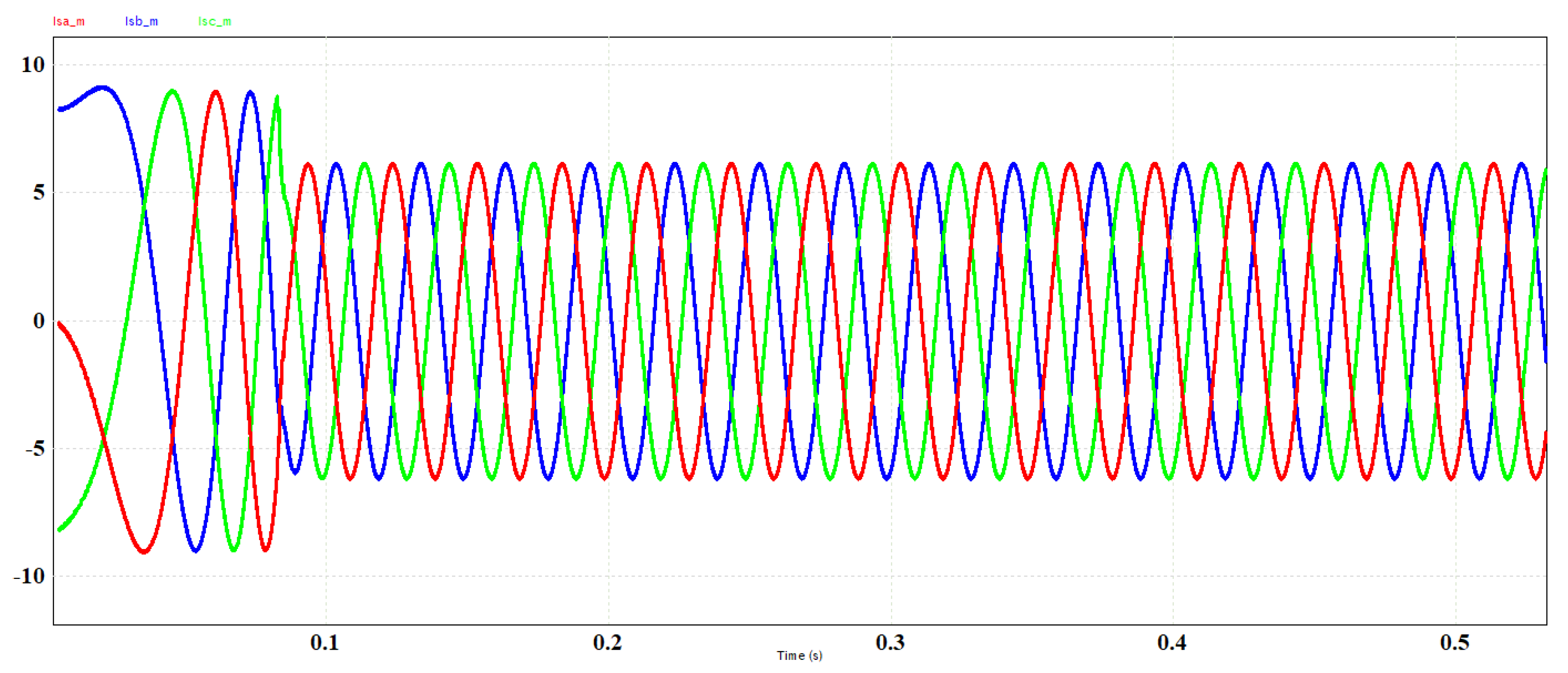
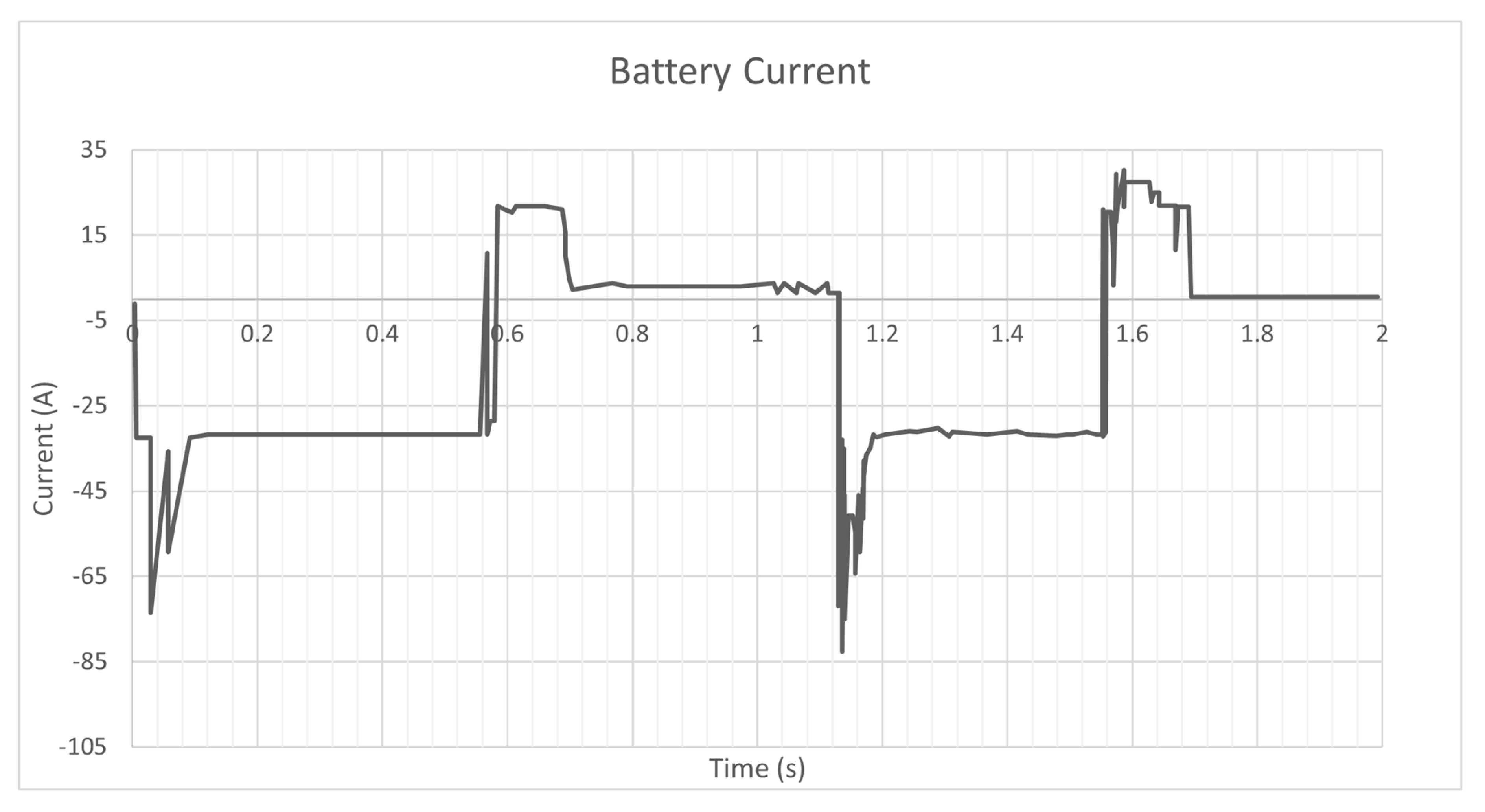
3. Simulation Results

The simulation setup is provided in Figure 4. The power stage includes a lithium-ion battery pack, a bidirectional dc-dc converter, a three-phase inverter, and the motor. Since the PSIM motor library was limited to only rotary motors, a permanent magnet linear synchronous motor (PMSM) was used. Thus, the angular velocity (as opposed to a linear velocity for an LSM) provided by the PMSM block was used to sense the speed for the controller. In terms of the control stage, typical FOC algorithm was used. However, to implement the regeneration system, a torque estimate was required to sense if the motor was in regenerative breaking or motoring mode. Thus, the additional control algorithm provided by PSIM was used.
The controller will then provide the required PWM signals to produce a three-phase current waveform with minimum harmonics and to acquire a wave that looks as sinusoidal as possible. The following figures are simulation results of the power inverter. Figure 5 shows the simulation results of the AC currents in motoring mode. The speed response is given in Figure 6.
Figure 7 highlights the directionality of the current in relation to the battery. This direction is dependent on if the pod is in fact driving, regenerative braking, or idling. For example, beginning at 0.5 s when the vehicle enters regenerative braking, we can see the current flowing into the battery and therefore returning energy to the system.
In Figure 8 the waveform represents the SOC during the various drive states of the simulation. The figure first shows a decreasing SOC which indicates that the vehicle is drawing current from the battery to drive. An increase in SOC then occurs as regenerative braking is employed returning potential energy to the battery module. Lastly, we see that a period of minimal drain upon the SOC in this time frame is representative of the LSM idling until driving is resumed.
Finite element analysis of the pod is given in Figure 9 and shows magnetic field safe values for humans as per IEEE C95.1.
Next, the simulation is run so that the ideal distance can be determined. Once the single coil is set up, the simulation is expanded to four coils as shown in Figure 10. The effect of the adjacent coils can be observed and recorded accordingly. Figure 11 illustrates the magnetic field strength of the active coils. These levels adhere to the IEC-60118 used in North America and Europe.

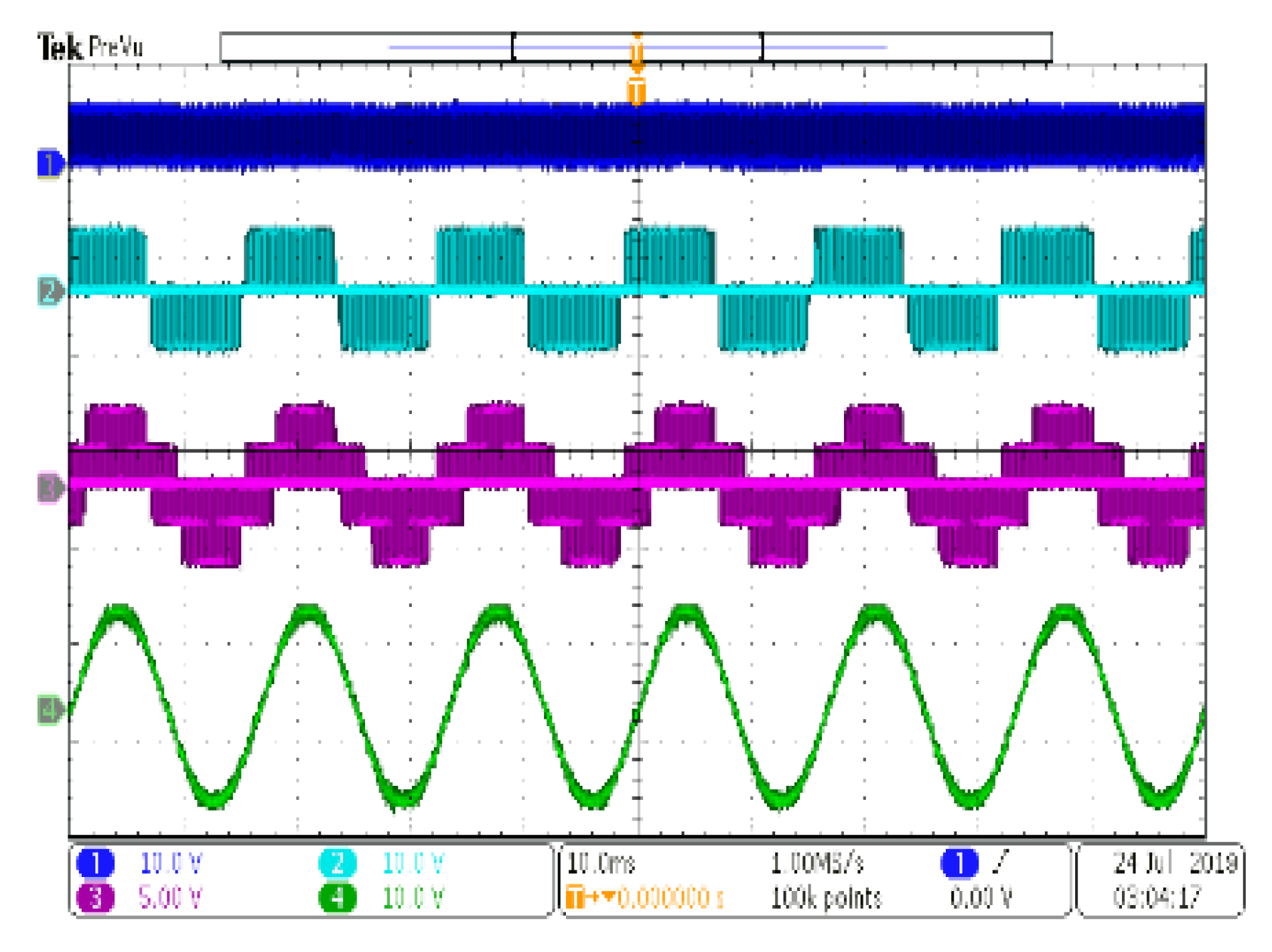
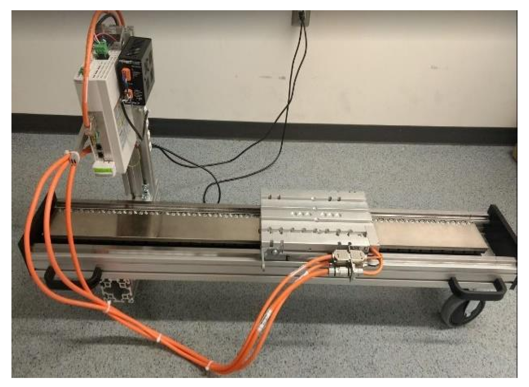
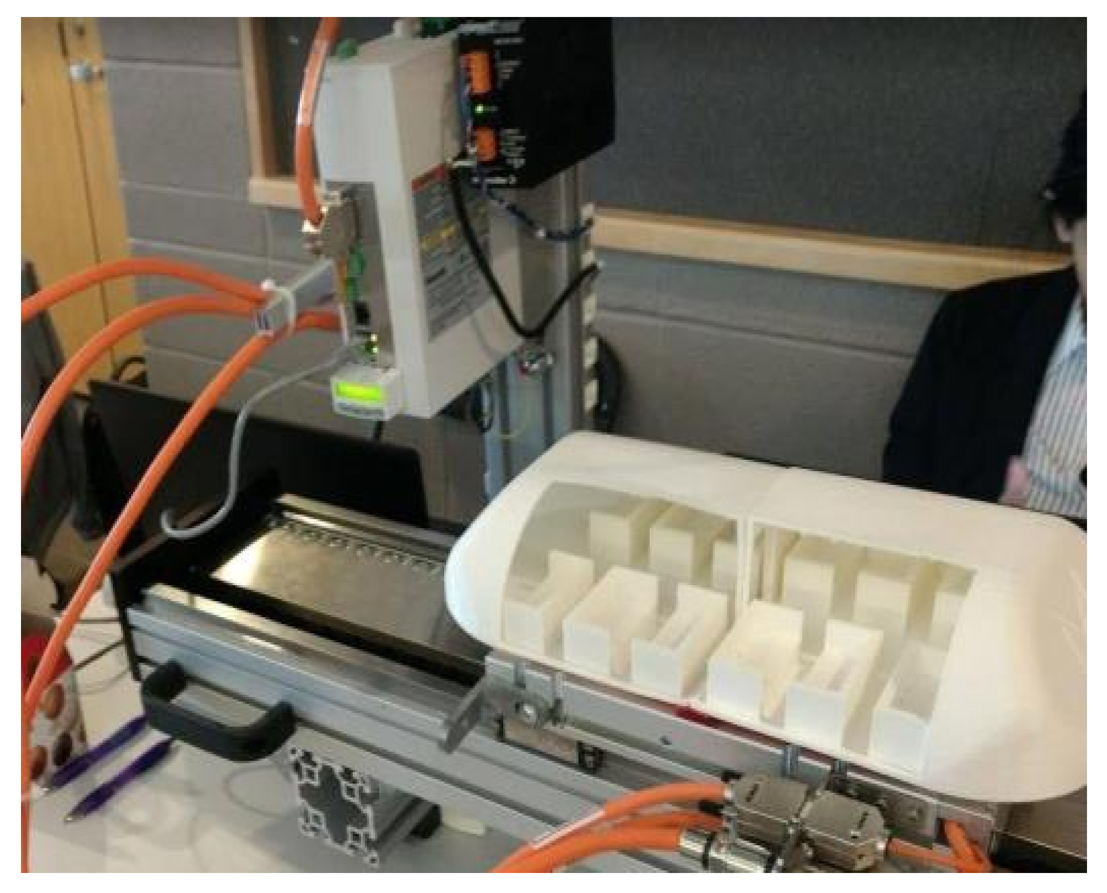
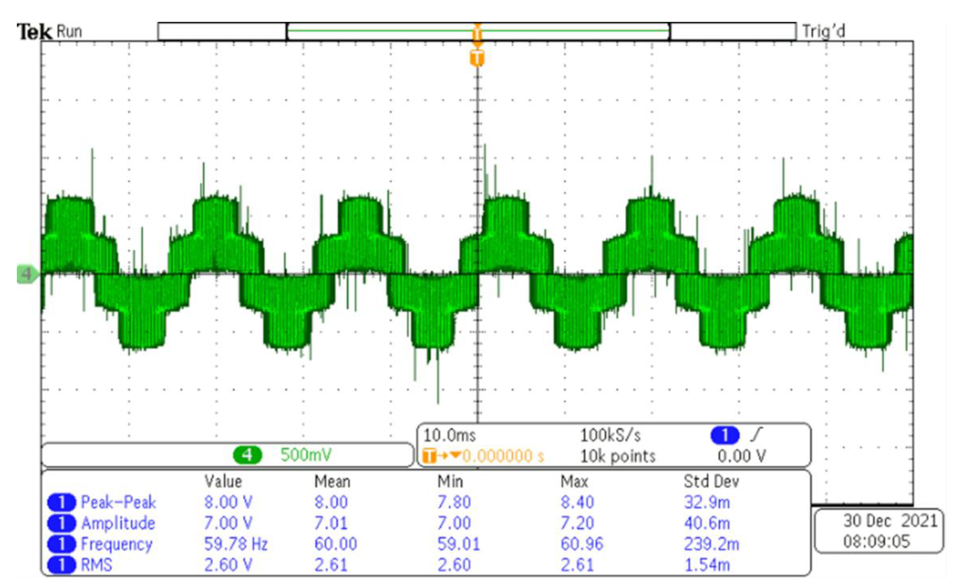
4. Experimental Analysis

Autodesk Eagle was used to design the printed circuit board (PCB). The hardware prototype of the inverter is circuit driven by the MIC4609 driver. A Texas Instrument microcontroller (TMS320F2808) was used to generate the PWM signals based on the proposed FOC. This prototype design was done to provide a proof of concept. The controller and the PCB circuit have similar components to the original proposed design. The prototype for the power inverter is shown in Figure 12. It consists of 6 surface mount IGBTs (RGT50NS65DGT) connected in a typical inverter circuit orientation. Using the data sheet bootstrap capacitors and diodes were chosen as recommended.
The waveforms generated by the output of the inverter are given in Figure 13 and Figure 14. Figure 13 shows the preliminary inverter output voltage. In Figure 14 the purple waveform is the voltage line feeding the load (linear motor). The green sinusoidal waveform below it is the AC current waveform of a single phase. The results are what is expected for the circuit output. The interface for controlling the linear motor was created using C++. It allows the control of position, velocity, and acceleration. It also provides real-time feedback of the motor’s status.
The developed inverter circuit was used to power and control the linear motor (provided by Bosch Rexroth). The prototype of the integration is shown in Figure 15 and Figure 16. Communication with the synchronous linear motor was achieved through Ethernet Protocols. The MCP015A-L040 drive was used to facilitate prototype integration.

5. Conclusions

A successful component design and system integration of the Hyperloop pod’s functionality is presented using PSIM simulation, C++ software interface, and a prototype hardware from “off-the-shelf” components. Simulations of field-oriented control for an equivalent rated rotary synchronous motor was built in PSIM. With intensive hardware and software integration methods, the goal to provide linear bidirectional movement for the prototype was achieved. The integrated system includes the linear synchronous motor, three-phase power inverter, and a battery pack. This was implemented on a small-scale prototype model. The three-phase inverter was designed using PSIM’s platform and tested by generating case study simulations that validated its functionality before integration. Additionally, the battery model was also implemented in PSIM and sized accordingly. Measured results from the inverter prototype are in good agreement with the simulation results. The operation of the full system integration proves that the design of the inverter and linear synchronous motor achieve a linear motion, with bidirectional movement for the pod prototype, in motoring and braking modes. The presented design provides a good starting point for a linear synchronous motor-based Hyperloop. However, the scale it was designed for is currently not capable of a full-sized passenger transportation. The nature of the system comes with high infrastructure build time and costs. Thus, various design trade-offs were needed to be made in terms of cost, size, power capabilities, etc. Nonetheless, future work for this study includes improving the design in various aspects such as fine-tuning and verifying the system in a hardware in the loop environment, designing it for a larger test track, and improving the prototype design capabilities to include additional data such as speed and acceleration. Hardware in the loop technology will be used in the hopes to reduce cost and prototyping time. A longer test track would provide a better understanding of the performance and efficiency. Additionally, this test track would provide a better study for the dynamic characteristics. This would require an improved prototype design with additional sensors to provide speed and acceleration values. Lastly, as this is the first iteration of the prototype, the design choices and trade-offs were very minimal. The prototype was designed for a proof of concept. The next iteration will be designed and better engineered to achieve an optimal design. Future work will also detail mechanical modeling and passenger ride comfort calculations. To summarize, the scope of this study is to provide some insight on the propulsion system design methodology and initial prototype results for the novel Hyperloop transportation system.

Author Contributions

Conceptualization, M.M.A. and M.Y.; methodology, M.B.; software, M.M.A. and F.M.; validation, N.B.; formal analysis, F.M.; investigation, M.B.; resources, M.Y.; data curation, R.L.; writing—original draft preparation, R.L.; writing—review and editing, M.B.; visualization, F.M.; supervision, M.Y.; project administration, M.Y.; funding acquisition, M.Y. All authors have read and agreed to the published version of the manuscript.

Funding

This work was supported by the Natural Science and Engineering Research Council of Canada in conjunction with Transport Canada (Fund number 210850). This was an invited paper and the APC discount was provided by MDPI. We thank MDPI for this opportunity.

Institutional Review Board Statement

This study did not require ethical approval. Not applicable.

Conflicts of Interest

The authors declare no conflict of interest.

Nomenclature

LIMLinear Induction Motor
LSMLinear Synchronous Motor
PMSMPermanent Magnet Synchronous Motor
EMSElectromagnetic Suspension
EDSElectrodynamic Suspension
PODReferring to Hyperloop Capsule/Vehicle
FOCField Oriented Control
SVPWMSpace Vector Pulse Width Modulation
uabcStator a, b, c phase to neutral voltages
RabcStator a, b, c phase resistances
iabcStator a, b, c phase currents
LabcMatrix of stator phase self and mutual inductances
Laa, Lbb, LccStator a, b, c phase self-inductances
Mab, Mac, Mba, Mbc, Mca, McbMutual inductances of stator a, b, c phases
ΨMabcStator a, b, c phase flux linkages from PMSM
TeElectromagnetic Torque
SOCState of Charge
EratedRated voltage of battery cell
QratedRated capacity of battery cell
RbatteryInternal resistance of the battery cell
NpNumber of cells in parallel of battery pack

References

  1. IEA. Transport: Improving the sustainability of passenger and freight transport, International Energy Agency. Available online: https://www.iea.org/topics/transport (accessed on 22 September 2019).
  2. Ji, W.Y.; Jeong, G.; Park, C.B.; Jo, I.H.; Lee, H.W. A Study of Non-Symmetric Double-Sided Linear Induction Motor for Hyperloop All-In-One System (Propulsion, Levitation, and Guidance). IEEE Trans. Magn. 2018, 11. [Google Scholar] [CrossRef]
  3. Janzen, R. TransPod Ultra-High-Speed Tube Transportation: Dynamics of Vehicles and Infrastructure. Procedia. Eng. 2017, 199, 8–17. [Google Scholar] [CrossRef]
  4. Hasirci, U.; Balikci, A.; Zabar, Z.; Birenbaum, L. Experimental performance investigation of a novel magnetic levitation system. IEEE Trans. Plasma. Sci. 2013, 5, 1174–1181. [Google Scholar] [CrossRef]
  5. Sayeed, J.M.; Abdelrahman, A.; Youssef, M.Z. Hyperloop Transportation System: Control, and Drive System Design. In Proceedings of the IEEE Energy Convers. Congr. Expo. (ECCE 2018), Portland, OR, USA, 23–27 September 2018; pp. 2767–2773. [Google Scholar] [CrossRef]
  6. Zhang, Z.; She, L.; Zhang, L.; Shang, C.; Chang, W. Structural optimal design of a permanent-electro magnetic suspension magnet for middle-low-speed maglev trains. IET Electr. Syst. Transp. 2011, 2, 61–68. [Google Scholar] [CrossRef]
  7. Lim, J.; Jeong, J.H.; Kim, C.H.; Ha, C.W.; Park, D.Y. Analysis and Experimental Evaluation of Normal Force of Linear Induction Motor for Maglev Vehicle. IEEE Trans. Magn. 2017, 11. [Google Scholar] [CrossRef]
  8. Jeong, J.H.; Lim, J.; Ha, C.W.; Kim, C.H.; Choi, J.Y. Thrust and efficiency analysis of linear induction motors for semi-high-speed Maglev trains using 2D finite element models. In Proceedings of the 2016 IEEE Conference on Electromagnetic Field Computation (CEFC), Miami, FL, USA, 13–16 November 2016. [Google Scholar] [CrossRef]
  9. Wang, H.; Li, J.; Qu, R.; Lai, J.; Huang, H.; Liu, H. Study on High Efficiency Permanent Magnet Linear Synchronous Motor for Maglev. IEEE Trans. Appl. Supercond. 2018, 3. [Google Scholar] [CrossRef]
  10. Boldea, I. Linear Electric Machines, Drives, and Maglevs Handbook, 1st ed.; CRC Press: Boca Raton, FL, USA, 2017. [Google Scholar]
  11. Yesilbag, E.; Ergene, L.T. Field oriented control of permanent magnet synchronous motors used in washers. In Proceedings of the 2014 16th International Power Electronics and Motion Control Conference and Exposition, Antalya, Turkey, 21–24 September 2014; pp. 1259–1264. [Google Scholar] [CrossRef]
  12. U.S.E.P. Agency. Global Greenhouse Gas Emissions Data. Available online: https://www.epa.gov/ghgemissions/global-greenhouse-gas-emissions-data (accessed on 21 March 2020).
  13. Voltes-Dorta, A.; Becker, E. The potential short-term impact of a Hyperloop service between San Francisco and Los Angeles on airport competition in California. Transp. Policy 2018, 71, 45–56. [Google Scholar] [CrossRef] [Green Version]
  14. You, C.; Zhang, R.; Wang, X.; Du, Y.; Ge, Q. Vector control of maglev PMLSM based on minimum loss SVPWM method. In Proceedings of the 2016 19th International Conference on Electrical Machines and Systems (ICEMS), Chiba, Japan, 13–16 November 2016. [Google Scholar]
  15. Sadat, A.R.; Shadabi, H.; Sabahi, M.; Sharifian, M.B.B. Tracking of X-Y direction positions with using permanent magnet linear synchronous motors. In Proceedings of the 2014 22nd Iranian Conference on Electrical Engineering (ICEE), Tehran, Iran, 20–22 May 2014; pp. 527–532. [Google Scholar] [CrossRef]
  16. Wang, K.; Ge, Q.; Shi, L.; Li, Y.; Zhang, Z. Development of ironless Halbach permanent magnet linear synchronous motor for traction of a novel maglev vehicle. In Proceedings of the 2017 11th International Symposium on Linear Drives for Industry Applications (LDIA), Osaka, Japan, 6–8 September 2017. [Google Scholar] [CrossRef]
  17. Kowal, B.; Ranosz, R.; Klodawski, M.; Jachimowski, R.; Piechna, J. Demand for passenger capsules for Hyperloop High-Speed Transportation System -case study from Poland. IEEE Trans. Transp. Electrif. 2021. [Google Scholar] [CrossRef]
  18. Tbaileh, A.; Elizondo, M.; Kintner-Meyer, M.; Vyakaranam, B.; Agrawal, U.; Dwyer, M.; Samaan, N. Modeling and Impact of Hyperloop Technology on the Electricity Grid. IEEE Trans. Power Syst. 2021, 5, 3938–3947. [Google Scholar] [CrossRef]
  19. Pan, S. Development of Permanent Magnet Tubular Linearmotor and Position Feedback Device Based on Hallsensor. Univ Wollongong Thesis Collect. 1954–2016. Available online: https://ro.uow.edu.au/theses/4852 (accessed on 14 December 2021).
  20. MATLAB, “PMLSM”. Available online: https://www.mathworks.com/help/physmod/sps/ref/pmlsm.html (accessed on 14 December 2021).
  21. Ong, C.-M. Dynamic Simulations of Electric Machines; Prentice Hall: Hoboken, NJ, USA, 1998. [Google Scholar]
  22. Giangrande, P.; Cupertino, F.; Pellegrino, G. Modelling of linear motor end-effects for saliency based sensorless control. In Proceedings of the 2010 IEEE Energy Conversion Congress and Exposition, Atlanta, GA, USA, 12 September 2010; pp. 3261–3268. [Google Scholar] [CrossRef]
  23. Platen, M.; Henneberger, G. Examination of leakage and end effects in a linear synchronous motor for vertical transportation by means of finite element computation. IEEE Trans. Magn. 2001, 37, 3640–3643. [Google Scholar] [CrossRef]
  24. Lu, J.; Ma, W. Research on end effect of linear induction machine for high-speed industrial transportation. IEEE Trans. Plasma Sci. 2011, 39, 116–120. [Google Scholar] [CrossRef]
  25. Gieras, J.F.; Piech, Z.J.B.; Tomczuk, B. Linear Synchronous Motors: Transportation and Automation Systems; CRC Press: Boca Raton, FL, USA, 2011. [Google Scholar]
  26. Abassi, M.; Khlaief, A.; Saadaoui, O.; Chaari, A.; Boussak, M. Performance analysis of FOC and DTC for PMSM drives using SVPWM technique. In Proceedings of the 16th Int. Conf. Sci. Tech. Autom. Control Comput. Eng. STA 2015, Monastir, Tunisia, 21–23 December 2015. [Google Scholar]
Figure 1. Block diagram for LSM, adapted from [25].
Robotics 11 00023 g001
Figure 2. Block diagram for FOC control scheme.
Robotics 11 00023 g002
Figure 3. Bidirectional DC-DC Converter Control System.
Robotics 11 00023 g003
Figure 4. Circuit setup for FOC of PMSM.
Robotics 11 00023 g004
Figure 5. Three-phase AC line currents (amperage vs. time).
Robotics 11 00023 g005
Figure 6. Speed response (rads/s vs. time).
Robotics 11 00023 g006
Figure 7. Battery current for regenerative breaking (amperage vs. time).
Robotics 11 00023 g007
Figure 8. SOC of the battery.
Robotics 11 00023 g008
Figure 9. Single Coil Setup in ANSYS Maxwell.
Robotics 11 00023 g009
Figure 10. Four coil simulations.
Robotics 11 00023 g010
Figure 11. Magnetic field strength across Z distance.
Robotics 11 00023 g011
Figure 12. Three-phase inverter prototype.
Robotics 11 00023 g012
Figure 13. Line to line voltage waveform (Vab); before the dv/dt filter of the motor.
Robotics 11 00023 g013
Figure 14. Prototype inverter circuit waveforms.
Robotics 11 00023 g014
Figure 15. Prototype linear motor.
Robotics 11 00023 g015
Figure 16. Prototype linear motor with test pod.
Robotics 11 00023 g016
Table 1. Motor parameters.
SymbolQuantityDescription
p8Poles
Rs0.065Stator Resistance
Ld0.001916d-axis inductance
Lq0.005q-axis inductance
Pmax50,000Max motor power
nmax5000Maximum rpm
Table 2. Battery Parameters.
ParametersValueUnits
Ns No. of cells in series70cells
Np No. of cells in parallel60cells
Erated Rated voltage3.6V
Ecut Discharge cut-off voltage2.5V
Qrated Rated capacity3.35Ah
Publisher’s Note: MDPI stays neutral with regard to jurisdictional claims in published maps and institutional affiliations.

