1. Introduction
Robot arms have been used as a substitute for human arms in ordinary and precision tasks. As they have become smaller and less expensive, they have been increasingly used in many fields. However, these robot arms are able to move only within the workspace where they have been installed. If work is needed in a different location or over a larger area, another robot arm must be used or the first must be re-installed. Therefore, alternative solutions have been developed, such as a robotic arm on a mobile robot, as proposed by the Mitsubishi Heavy Industries Group [
1], or a robotic arm on a drone, as developed by Oonishi et al. [
2]. These studies address the disadvantage of robot arms, which is that they are limited to a small workspace. However, it is not easy to introduce these robots into some environments such as factories and agricultural sites. Therefore, wearable robots have been attracting attention. Wearable robot arms have been shown to reduce the burden on a user and improve work efficiency [
3,
4]. Wearable robot arms have been considered for practical application because they do not need to move autonomously and their cost is low. An example of a practical application of wearable devices is the power suit [
5]. Power suits are expected to reduce workloads and assist in the rehabilitation of users such as the elderly. Moreover, wearable robot arms that perform a cooperative task with a user have attracted much attention [
6]. Attaching a robot arm to a user enables the user to perform tasks that a single human cannot perform, and it is possible to improve work efficiency. In addition, a wearable robot arm can maintain a certain distance from the user because it is mounted on the user. Therefore, the wearable robot arm can easily support cooperative tasks near the user. Wearable robot arms with these features are expected to be used in the workplace and daily life.
However, two challenges remain in the application of wearable robot arms: the weight burden on the user and the operability of the arm. When dexterity is required in a robot arm, high performance actuators are needed. As a result, the actuators must be high power and heavy. The root joint inevitably needs a heavy actuator because the required output torque of the actuator increases as it becomes closer to the root joint of the robot arm. Thus, the total weight of the robot arm increases, which increases the burden on the user. In addition, robot arms used in factories are subject to strict regulations such as the prohibition of intrusions into the moving parts of the robot arm and emergency stop devices. This is because if the wearable robot arm is heavy, it could be dangerous. Reducing the weight of wearable robot arm hence increases its safety and practicality.
The “operability” of a wearable robot arm refers to how it is operated when the user’s hands are busy. To solve this problem, manipulation methods have been developed, such as [
7], which manipulates a robot arm using muscle potential and the “face vector” approach [
8], which uses the direction of the user’s face to determine the 3D target position. However, irregular movements of the robot arm can be a danger to the user, as Nimawat et al. pointed out in [
9], which explained the risk of impact on the user due to user error or misrecognition in the user interface. This risk is caused by the difficulty of operating a robot arm using a user interface when all the joints of the robot arm are dynamically driven.
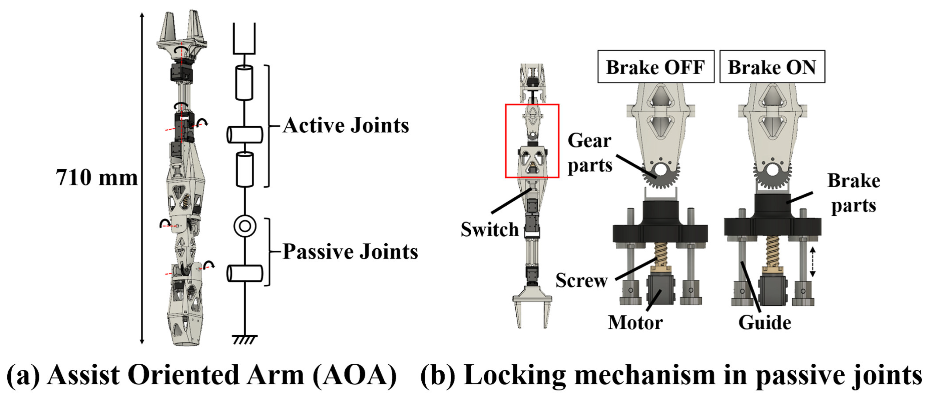
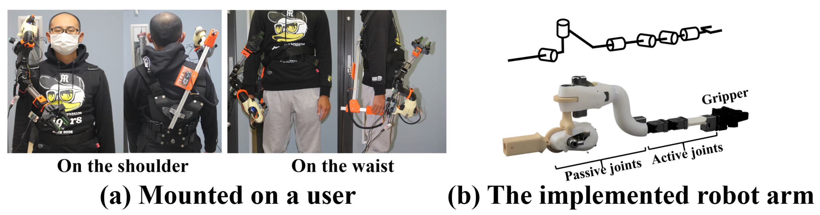
There are limits to how well the weight and operability problems can be solved in a robot arm mechanism that dynamically drives all joints using actuators. Therefore, we proposed a wearable robot arm called the Assist Oriented Arm (AOA) that is lightweight and safe but retains its operability [
10] (
Figure 1a). In a conventional wearable robot arm, the angle and force of all joints are controlled by actuators, leading to weight and safety issues. By contrast, joints with different roles were used in the AOA based on the movement of the arm during human work. In humans, the shoulder joint is used to carry the hand to the target workspace before starting the work, and then the tip of the arm is dynamically used to perform the work. The AOA uses a hybrid actuation system that combines two types of joints: active joints that are dynamically driven and passive joints that are directly moved by the user by handling the robot arm. Active joints are driven by actuators in the same way as a conventional robot arm. The passive joint uses a locking mechanism to fix the joint angle, as shown in
Figure 1b. A switch mounted on the passive joint turns the locking mechanism on and off. While the switch is pressed, the brake component engages the gear component to lock the angle of the joint. When the switch is released, the lock is released and the joint can be driven freely. Therefore, the joints can be fixed with high torque even with lower power and smaller actuators than before. We performed experiments to evaluate the influence of using the hybrid actuation system in [
10] on work efficiency and we were able to reduce the weight of the robot arm without compromising its operability, thus enabling it to be attached to the chest, shoulders, and other attachment positions for assisting with in various tasks.
In this study, the wearable robot arm was optimized for the pick-up task as follows. First, we defined the average human workspace for a wearable robot arm that provides task assistance. Based on the average human workspace, the details of the robot arm were determined. Second, to determine the optimal wearing position for the user, we determined the wearing position with the widest cooperative workspace between the robot arm and the user. We then selected mounting positions such that the body of the robot arm interferes with the user’s hand movement as little as possible. Finally, the robot arm was mounted on subjects at the selected mounting positions, and the position with the least weight burden was determined.
2. Related Work
Several other wearable robot arms have been proposed, and the specifications of each wearing position and the degrees of freedom (DoF) of these existing arms are summarized in
Table 1. Baldin et al. [
11,
12] used a backpack-type attachment device to mount a robotic arm on a user so that it can grasp and support heavy objects on behalf of the user. Stability and balance must be considered in this type of robot arm because it needs to be able to support heavy weights. In addition, Federico et al. [
13] modified a previously proposed robotic lower limb [
12] to support the user’s posture during work. This limb is mounted at the waist and supports the user like a leg. Baldin et al. proposed a wearable robotic arm that is mounted on the shoulder to assist in the installation of ceiling panels [
14]. A 5-DoF robotic arm supports the ceiling panel based on the input from an inertial measurement unit sensor attached to the user’s hand, leaving the user’s hands free to work on the ceiling panel. Vatsal et al. [
15] studied a robotic arm that is attached to the elbow and performs tasks in place of a user when both hands of the user are busy. The large size of the workspace is achieved with minimal link length by attaching the robot arm to the user’s arm.
In addition to the above arms, other wearable robot arms that interact with humans have been proposed, such as those by Saraiji et al. [
16] and Sasaki et al. [
17]. The arm in [
16] is a wearable device that integrates a robotic arm and a camera. A remote partner controls the robotic arm attached to the user using a head-mounted display and a controller. The arm in [
17] is a 7-DoF robotic arm synchronized with a human leg using motion capture. Because it is synchronized with the user’s feet, it can interact intuitively like a third arm. In these cases, the wearable robot arm can perform tasks requiring the same level of dexterity as that of the user. In addition, it is necessary to secure a large workspace for interaction with the user. Therefore, an arm with multiple DoFs (e.g., six DoFs) is required.
These robot arms have different mounting positions and joint configurations because of their different target tasks. Tanaka et al. [
18] proposed a framework for the evaluation and design of assistive robots based on the ICF (International Classification of Functioning, Disability, and Health [
19]). In this study, the use of the subject’s hands was analyzed in terms of movement frequency using a video recording of daily life obtained by a head-mounted camera. According to [
18], 90% of tasks in a person’s daily life are “lifting” tasks. In other words, if a wearable robot arm can assist with lifting, 90% of a person’s daily tasks can be assisted. They also stated that 90% of the objects lifted are less than 300 g. Therefore, in this study, the objective of the AOA is to lift an object weighing 300 g or less. In this work, only light objects like a cup or pen are lifted. Therefore, the lifting task is called “pick-up”. The robot joint configuration and mounting position needed to perform this task are examined in this study.
The position of a wearable robot arm was previously examined in [
20] by Nakabayashi et al. They investigated the range of motion obtained by changing the link lengths and joint configurations of the robot arm at three attachment points: the waist, chest, and shoulder. Based on the results, the optimal mounting position and robot arm specifications were obtained by evaluating the coordination and extendability of the user’s workspace. They also studied which links of the robot arm can invade the user’s workspace. In contrast, this study investigates the joint configuration and link length of a wearable robotic arm with a wide cooperative workspace with the user. As a result, the range of motion is less invasive according to the indexes of cooperativity, extendability, and invasiveness used in [
20].
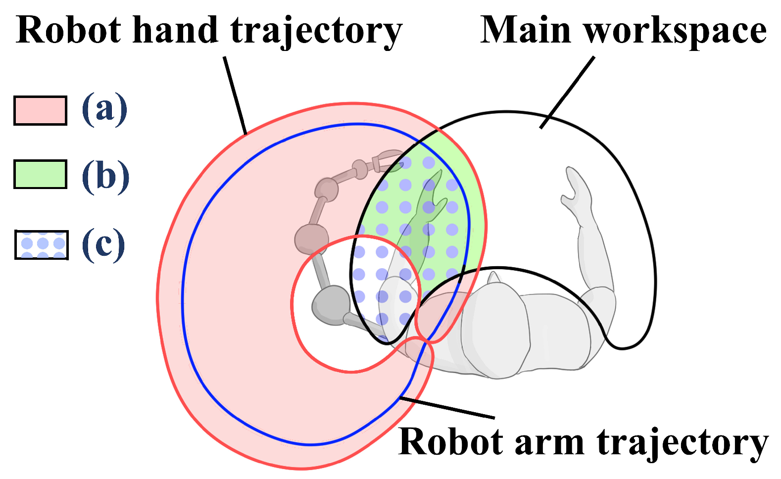
Figure 2 shows the details of extensive workspace, cooperative workspace, and invasive workspace. The main workspace is within easy reach of the user. The extensive workspace
Figure 2a is the movable area of the robot hand outside the main workspace. The cooperative workspace
Figure 2b is the movable area of the robot hand in the main workspace. The invasive workspace
Figure 2c is the range within the main workspace where the body of the robot arm interferes when the robot hand is moved. The following equations define the cooperativeness, extensiveness, and invasiveness indices by [
20].
where
is the volume of the main workspace,
is the volume of the extensive workspace,
is the volume of the cooperative workspace,
is the volume of workspace invasiveness,
is the volume of the robot hand trajectory domain and
is the volume of the robot arm trajectory domain. We use the wearable robot arm studied, and select the optimal mounting position.
3. Workspace Range and Human Body Dimensions
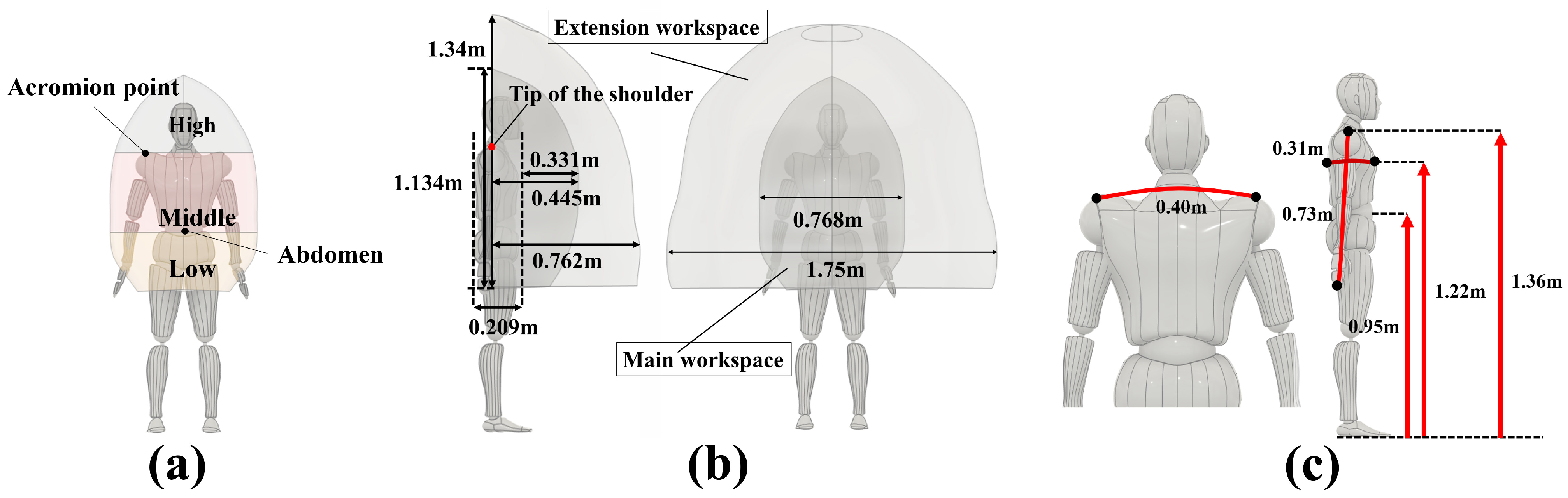
The attachment position of the wearable robot arm depends on the task. As shown in
Figure 3a, the user’s workspace is classified into three categories, high, middle, and low, based on the acromion point and abdominal position. To define the workspace requirements, we used data from the Life Engineering Research Center [
21], which measured the width and depth of the workspace accessible by human movements. These data were used to determine the average range of motion with respect to the right hand of the subjects. As a constraint, the subject kept the soles of both feet on the ground. Because the data are based on the right acromion point, the range of motion of the left hand was defined using horizontally flipped data.
Figure 3b shows the main workspace and extensive workspaces according to these data [
21]. The main workspace is the area in which the user can comfortably move their hands. The extensive workspace is the area that the user can reach with difficulty. The National Institute of Advanced Industrial Science and Technology’s (AIST) AIST/HQL human body dimensions and shape database [
22] was used to obtain the reference dimensions of the human body. In addition,
Figure 3c shows the average human body dimensions. These reference data and dimensions were used to study the wearable robot arm’s joint configuration, link length, and mounting position.
4. Joint Configuration and Link Lengths of the AOA
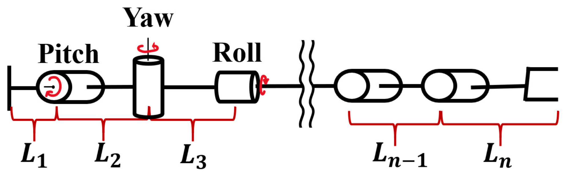
The pick-up task described above was used as the target task. Our aim is to determine the best joint configuration and link length in the passive and active joints of the AOA. As shown in
Figure 4, the link length from the root position to the first joint of the robot arm is
, and the links between subsequent joints are denoted as
,
,
, and
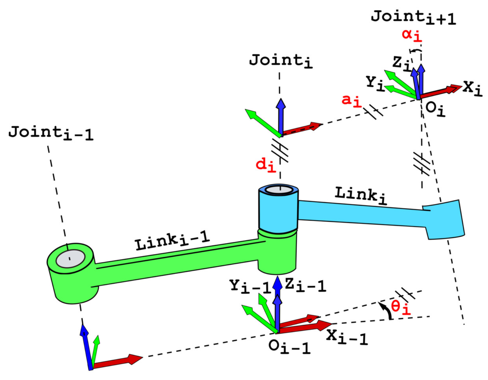
. The rotation axes of the joints are expressed using pitch, yaw, and roll. The link lengths and joint configurations of the robot arm are studied using kinematics. Using the Denevit-Hartenberg representation of
Figure 5, the transformation between the reference frame
and the reference frame
i can be easily calculated by the following Equation (
4).
4.1. Passive Joint
In a passive joint, the joint angle lock is turned on and off by a switch attached to the body of the robot arm, and the user moves the hand to the target workspace while holding the robot arm. The switch should be placed in a position that is easy for the user to reach and press, and it should not be affected by the joint angle or posture of the robot arm. If the switch is mounted on the link of the active joint, it is difficult for the user to press the switch because the posture of the robot arm can change substantially before and after an operation. In a passive joint, the posture of the joint does not change during the operation, and it is appropriate to implement the switch on the link of the passive joint.
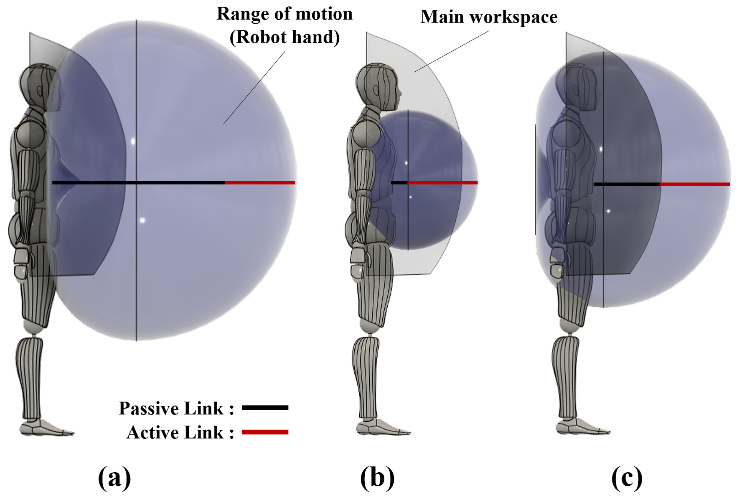
The maximum range of the passive-joint links should remain within the area that the user can easily reach. However, the range of motion of the robot arm varies depending on their length.
Figure 6 shows the change in the range of motion of the robot hand when the length of the passive joint is changed. When calculating the range of motion, the active joints were assumed to be constant. In addition, the angles of these joints’ angles were varied from
to
. As shown in
Figure 6a, if the links extend beyond the main working range, the range of motion of the robot arm increases, but the range of coordination in the user’s main workspace decreases. In
Figure 6b, the lengths of the passive-joint links are short, and the overall range of motion of the robot arm is narrow. Moreover, the cooperative workspace is wide, but the extensive workspace is narrow. In
Figure 6c, the link length of the passive joint is set to equal the user’s reach. In this case, there is no bias in the cooperative and extensive workspace, and the switch to turn the lock on and off can be located within arm’s reach of the user. Therefore, when the robot arm is mounted on the front of the user, the total length of the passive-joint links should be 0.33 m from the front of the user to the main workspace, according to the dimensions in
Figure 3b. When mounting the prototype of the AOA, a gap of about 0.05 m is required for the vest and the fixed parts of the robot arm. Therefore, L1 requires 0.05 m, and the preferred total length of the passive-joint links for L2 and L3 is 0.28 m.
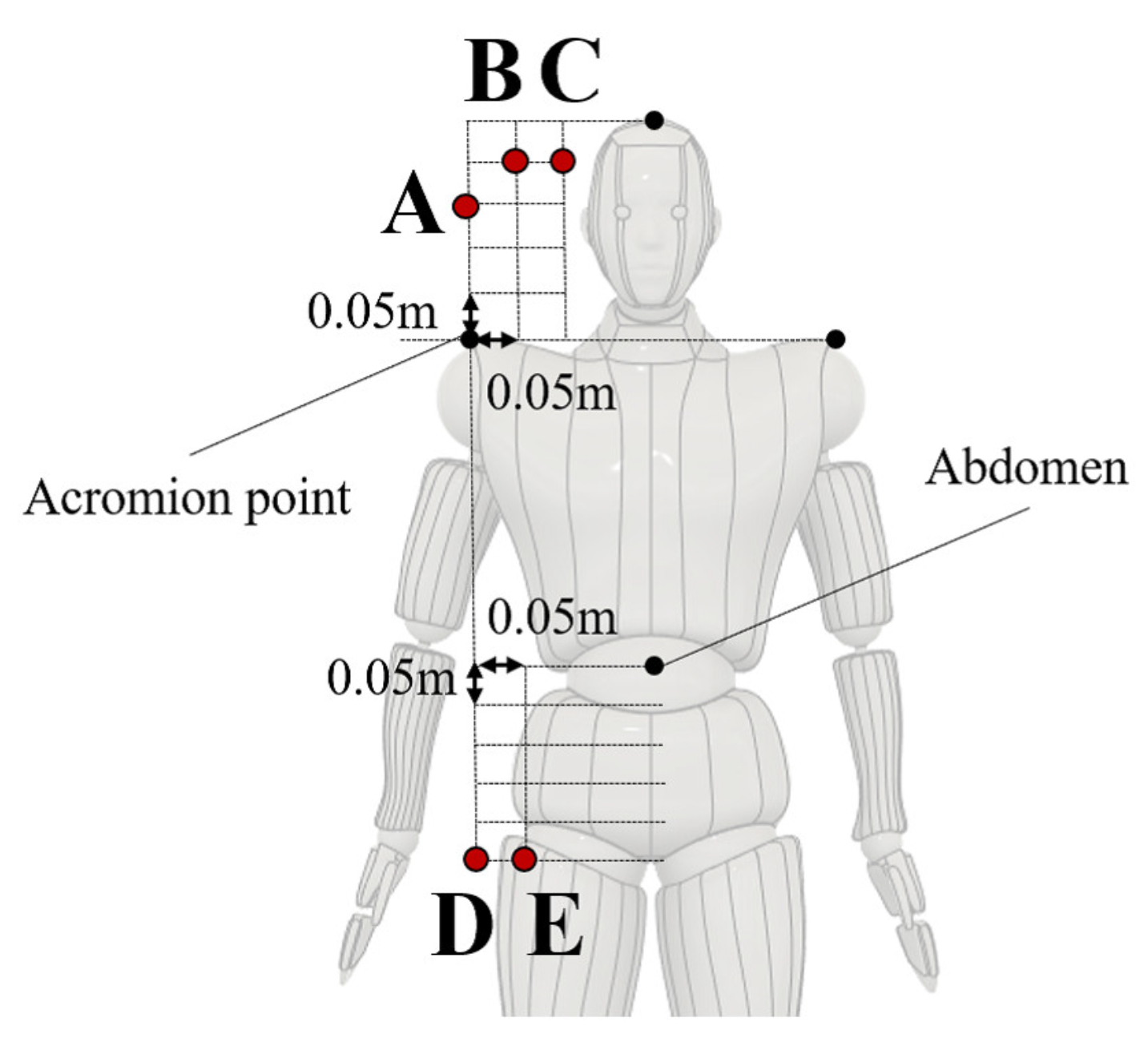
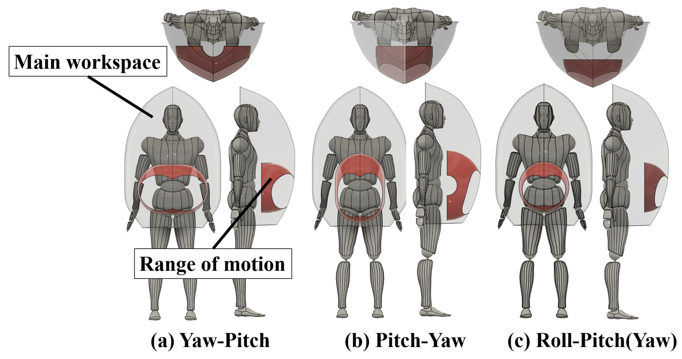
Next, we consider the configuration of the passive joint. The aim of the passive joint is to move the robot arm’s hand to the workspace. In addition, because it is mounted on a human, it is necessary to minimize the joint configuration to consider weight and safety. The minimum number of DoF to move the tip of the robot arm in three dimensions is two. Of the three rotation axes roll, pitch, and yaw, roll-pitch and roll-yaw are combined when the roll rotation is placed at the root position. However, both combinations have the same range of motion. The configuration in which roll rotation is provided at the tip of the robot arm should be excluded because it is movable only in two dimensions. We consider a joint configuration and a link length that can move widely within the user’s main work range. In this case, the central position of the body is used to maximize the cooperative workspace of the robot arm and the user. The center position of each height range shown in
Figure 3 (high, middle, and low) is selected as a mounting position. We then compare the range of the passive joint using these three mounting positions for a maximum link length of the passive joint of 0.28 m, and various lengths of
and
in steps of 0.01 m. We considered the joint configuration, which is wider in the work envelope of the wearable robot arm within the user’s workspace.
Figure 7 shows the maximum cooperative workspace for each joint configuration by using kinematics. The red area in
Figure 7 shows the range of motion of the passive joints within the user’s main workspace. A roll-pitch configuration has a narrower range than pitch-yaw and yaw-pitch configurations because it moves in a hemisphere around the pitch rotation axis. In addition, the work envelopes of the pitch-yaw and yaw-pitch configurations are similar, but the cooperative workspaces are different.
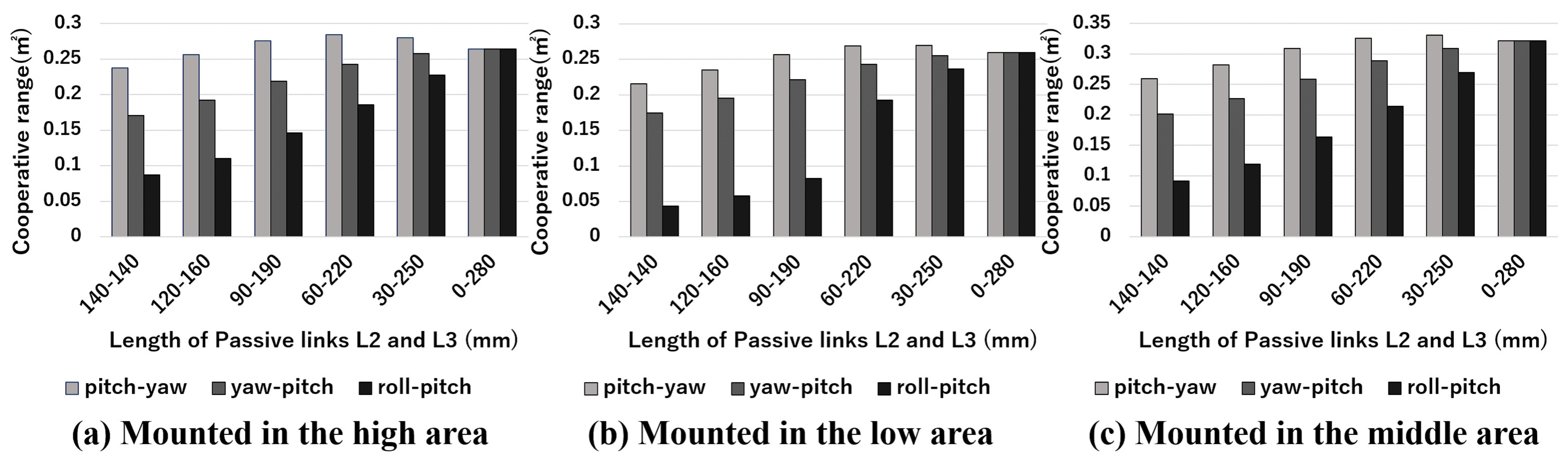
Figure 8 compares the work envelope of the passive joint when it is mounted in the high, middle, and low positions for each joint configuration. In all three positions, the pitch-yaw configuration has a wide range of motion within the user’s main workspace. In the relationship between link length and work envelope, the work envelope is widest when
is 0.03 m and
is 0.25 m. Therefore, these values were used.
Table 2 lists the specifications of the passive joints.
Table 3 shows the DH parameters from the root to the tip of the passive joint. Based on these parameters, the equation for tip of passive joints is shown below.
These link lengths and joint configurations were used to study the joint configurations and link lengths of the active joints in this research.
4.2. Active Joint
Active joints are used for dynamic movements that cannot be achieved with passive joints alone. We consider the joint configurations and link lengths required for the dynamic pick-up task. The configuration of the active joint depends on the target task. For example, when the posture of an object needs to be controlled in three dimensions, the number of DoFs required for the joints increases. However, a wearable robot arm is mounted on a user. Therefore, the position of the robot arm can change because of the user’s movement. Wearable robotic arms are better suited for lifting and moving objects than for detailed dexterous tasks. Because the weight of the robot arm increases as the number of DoFs increases, it is necessary to minimize the joint configuration and passive joints. In the workspace of the active joint, cooperative and extensive workspaces are required. The cooperative workspace is the overlap in the ranges of motion between the robot arm and the user’s arms. The extensive workspace is the area in the workspace that is outside the cooperative workspace. In some cases, the extensive workspace is essential, for example, in a task where a user uses lights in the extensive workspace that dynamically illuminate the workspace. In such a task, if the active joint holding the light is within the cooperative workspace, this would interfere with the user’s hand and affect the work. An example of a cooperative area task is when the robot arm holds an object within the cooperative workspace, such as during soldering. It is necessary to consider the DoFs and link length to keep both workspaces in balance.
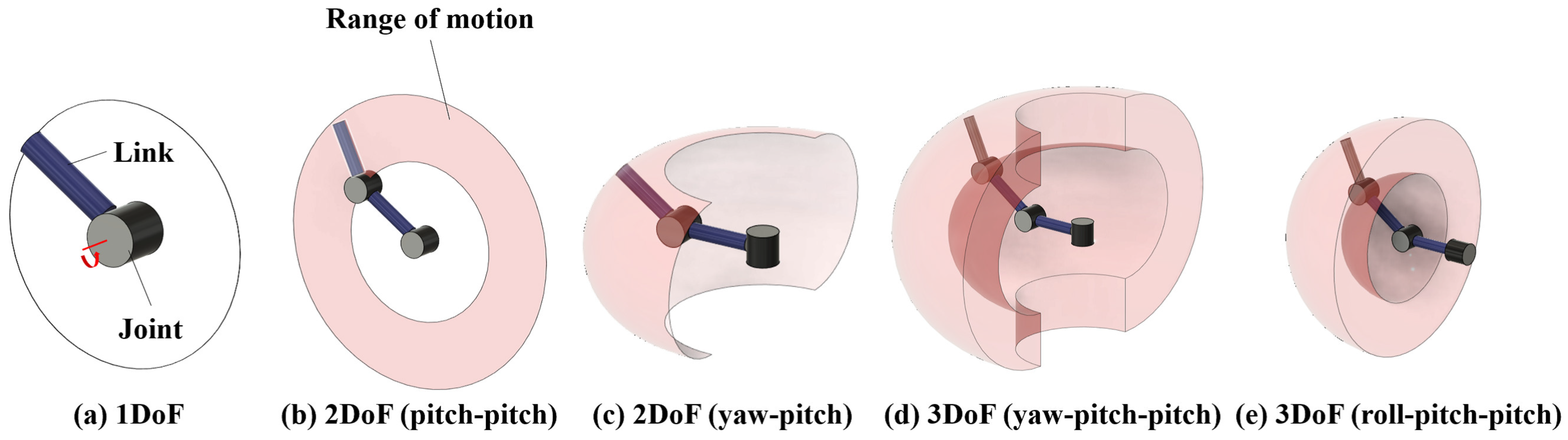
The requirements for active joints are a wide range of motion and minimal posture control when grasping an object. The joint arrangement of a typical robot arm is shown in
Figure 9. In the case of
Figure 9a–c, the range of motion is a line or plane, which greatly limits the tasks that can be performed. In the case of
Figure 9d,e in the figure, more movements are possible compared to
Figure 9a–c because they are movable in three dimensions. However, the tasks such as pickup and manipulation require more than 4DoF because of necessary for attitude control of the end-effector. For the object lifting task, which is the objective of this research,
Figure 9a–e can also perform the task. However, lifting objects commonly used in daily life, such as cups and cables, requires a three-dimensional range of motion and posture control of the end-effector. Therefore, in this study, we use the joint configuration shown in
Figure 9d,e.
For active joints, the longer the link length, the wider the range of motion. However, the longer the link length, the greater the burden on the user. If the maximum link length of an active joint is set to be longer than the extensive workspace shown in
Figure 3b, the range of motion becomes wider, but the range of motion becomes excessive, resulting in a greater burden on the user. In addition, if the maximum link length of the active joint is too short, the range of motion becomes narrow and the coordination and extensibility become low. Therefore, we set the length of the active joint to 0.317 m, which is the maximum extensive workspace, to ensure the maximum cooperative and extensive workspace between the user and the robot arm. In the case of
Figure 9d, the robot arm can move in three dimensions, but three joints need to be placed on the active joint link. The maximum link length of the active joint is limited, and a large number of joints would conversely reduce the range of motion. However, in the case of
Figure 9e, by placing the root-roll joint on the link of the passive joint, a wide range of motion can be achieved without putting pressure on the range of motion of the active joint. In addition, the installation of the roll rotation on the link of the passive joint does not reduce the range of motion of the passive joint. Therefore, a roll-pitch-pitch joint configuration was adopted. Roll-yaw-yaw is the same as roll-pitch-pitch by rotating
in the roll direction. A roll joint is provided at the end of the active joint for minimum posture control of the end-effector, and four degrees of freedom (roll-pitch-pitch-roll) have used. Thus, we achieve the minimum posture control required for grasping and lifting an object.
In the multiple joints on the same rotation axis, the range of motion varies depending on the link length between the joints. Therefore, we solved the kinematics using the parameters in
Table 4 and calculated the range of motion using the following equation.
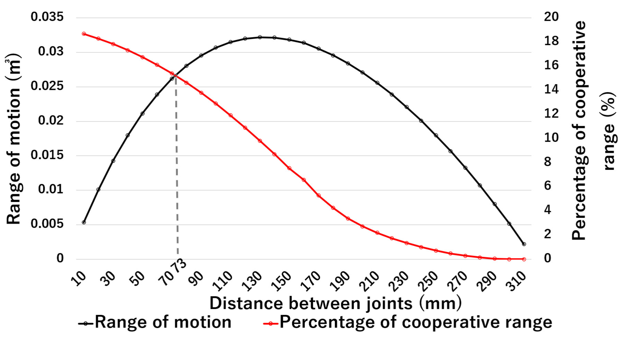
As shown in
Figure 10, where the gray line shows the percentage of the work envelope that is also cooperative workspace, and the black line shows the range of motion of the wearable robot arm. Moreover, joint intervals of 0.13 m yield the broadest range of motion. However, the percentage of the cooperative workspace in the work envelope is small. With a link length of 0.073 m, it is possible to ensure the broadest range of motion while retaining a large cooperative workspace. The specifications of the active joints considered in this study are listed in
Table 5. The joint configuration and link lengths of the active joints (
Table 5) and passive joints (
Table 2) were used to study the optimal wearing position for user.
6. Conclusions
In contrast to an industrial robot arm, a wearable robot arm does not need all of its joints to be controlled by actuators. A combination of passively driven passive joints and dynamically driven active joints was considered in this study to reduce the weight and increase the safety of a wearable robot arm. This study investigated the optimal configuration of DoFs, link length, and mounting position for the wearable robot arm. The mounting position on the user was selected based on average human body dimensions and average range of motion of the arms. The optimal mounting position was determined based on the ratio of the cooperative workspace to the invasive workspace. Because the wearable robot arm is mounted on the user, the operating range can be tailored to the user’s task. This approach also has a significant advantage in that it can provide a wide cooperative workspace. In recent years, wearable robotic arms have been widely studied, and each wearable robotic arm has been considered in various wearing positions. It is not easy to generalize which mounting position is best because the optimal position varies depending on the work and the DoFs of the robot arm. However, the wearable robot arm considered in this paper was studied based on the joint configuration, link length, and wearing position. This arm is needed to perform the lifting task, which accounts for 90% of daily tasks. Lifting is a task that can be applied not only in daily life but also in various fields such as factories and agriculture. Therefore, the investigations made in this paper will contribute to the generalization of wearable robot arms. If the wearing position is standardized, it will be possible to compare wearable robot arms, which is difficult at present, and better wearable robot arms can be considered. The future work of this research will be to develop and study a user interface for task support based on the lifting task using the wearable robot arm AOA.


